Embed Size (px)
Citation preview

8/10/2019 GEK111712 Control & Protection
http://slidepdf.com/reader/full/gek111712-control-protection 1/24
gGEK 111712
June 2007
GE Energy
These instructions do not purport to cover all details or variations in equipment nor to provide for every possible contingency to be met in connection with installation, operation or maintenance. Should furtherinformation be desired or should particular problems arise which are not covered sufficiently for the purchaser's
purposes the matter should be referred to the GE Company.
© 2007 General Electric Company
Control and Protection Articles
DLN2.6+ Gas Fuel System

8/10/2019 GEK111712 Control & Protection
http://slidepdf.com/reader/full/gek111712-control-protection 2/24
8/10/2019 GEK111712 Control & Protection
http://slidepdf.com/reader/full/gek111712-control-protection 3/24
Control and Protection Articles DLN2.6+ Gas Fuel System GEK 111712
3
TABLE OF CONTENTS
I. GENERAL ..................................................................................................................................................... 4 II. EQUIPMENT................................................................................................................................................. 4
A. Gas Flow Measurement (96FM-1)............................................................................................................ 4
B. Gas Fuel Auxiliary Stop Valve (VS4-1) ................................................................................................... 4 C. Stop/Speed Ratio Valve (VSR-1).............................................................................................................. 4 D. Gas Fuel Control Valves (VGC-1, VGC-2, VGC-3, VGC-4)................................................................... 5 E. Gas Purge Block Valves (VA13-1, VA13-2, VA13-20, VA13-21, VA13-3, VA13-4, VA13-23, VA12-
24) ............................................................................................................................................................. 5 F. Gas Purge Pressure Ratio Monitoring (96GN-1, 96GN-2, 96GN-3, 96GN-4) ......................................... 5
III. OPERATION................................................................................................................................................. 5 A. General ...................................................................................................................................................... 5 B. Pre-start Conditions................................................................................................................................... 7 C. Startup and Loading Operation ................................................................................................................. 8
IV. CONTROL................................................................................................................................................... 12 A. P2 Pressure Control................................................................................................................................. 12
B. Gas Flow and Split Control..................................................................................................................... 15 C. Gas Fuel Temperature Compensation..................................................................................................... 16 D. Gas Purge Control ................................................................................................................................... 17
V. PROTECTION ............................................................................................................................................ 17 A. P2 Pressure Control Protection and SRV Position Control Protection ................................................... 18 B. Fuel Temperature and Modified Wobbe Index Protection...................................................................... 18 C. Independent Flow Path Purge Protection................................................................................................ 19
LIST OF FIGURES
Figure 1. DLN2.6+ Fuel Nozzle Arrangement....................................................................................................... 6
Figure 2. Gas Fuel Leak Test Function Block Diagram....................................................................................... 10 Figure 3. SRV P2 Pressure Control Algorithm Diagram ..................................................................................... 13 Figure 4. SRV Speed Ratio Valve Control Schematic......................................................................................... 14 Figure 5. GCV Control Algorithm Diagram ........................................................................................................ 15 Figure 6. GCV Control Schematic ....................................................................................................................... 16
LIST OF TABLES
Table 1. DLN2.6+ Mode Staging Diagram............................................................................................................ 7 Table 2. Protective levels and actions for the Gas Fuel System – Gas Pressure.................................................. 18
Table 3. Independent Flow Path Purge Protection............................................................................................... 20
8/10/2019 GEK111712 Control & Protection
http://slidepdf.com/reader/full/gek111712-control-protection 4/24
GEK 111712 Control and Protection Articles DLN2.6+ Gas Fuel System
4
I. GENERAL
The Gas Fuel System's function is to provide accurate and repeatable gas fuel flow, and flow split control
for a multi-stream fuel injection system DLN2.6+. It also provides safe and reliable isolation from the gas
fuel source. This unit use preheated Gas Fuel @ 365 deg F.
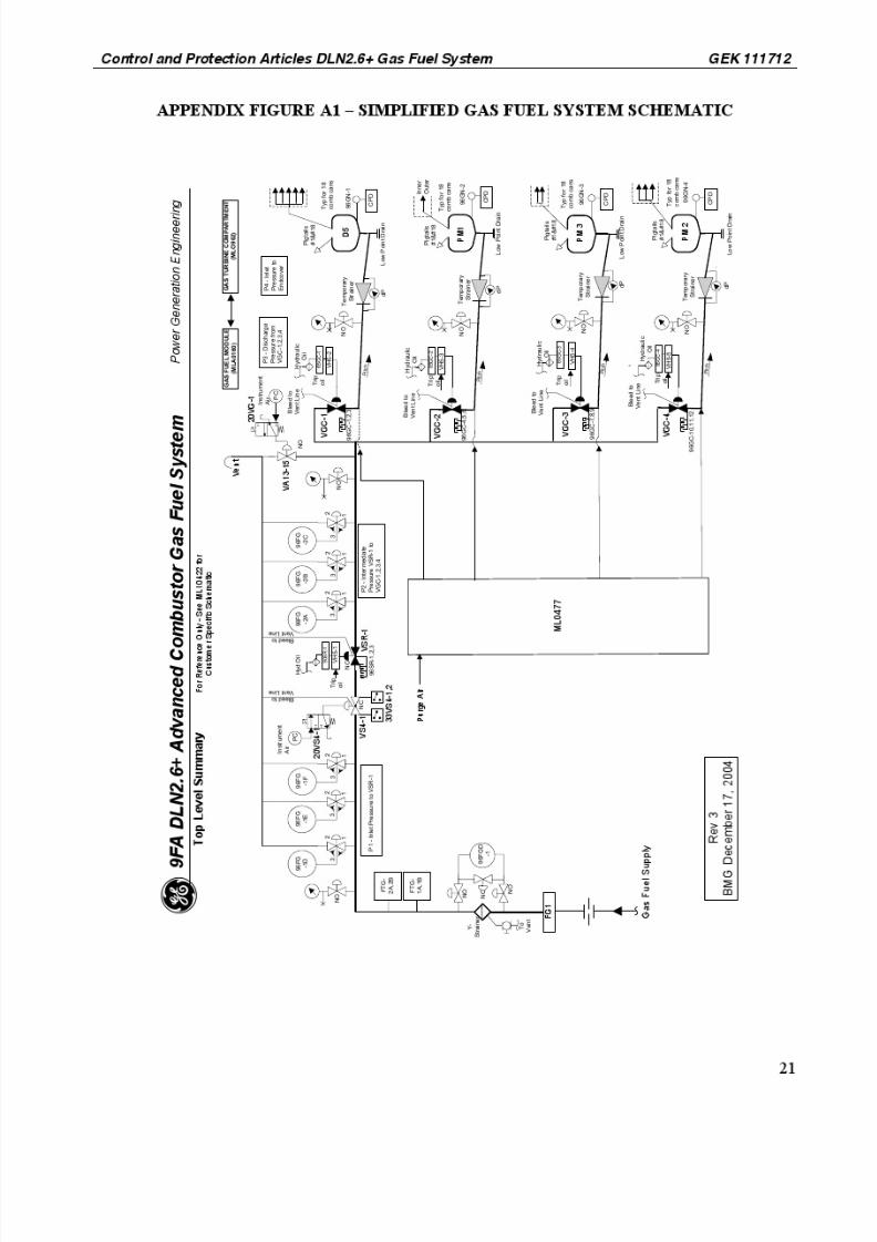
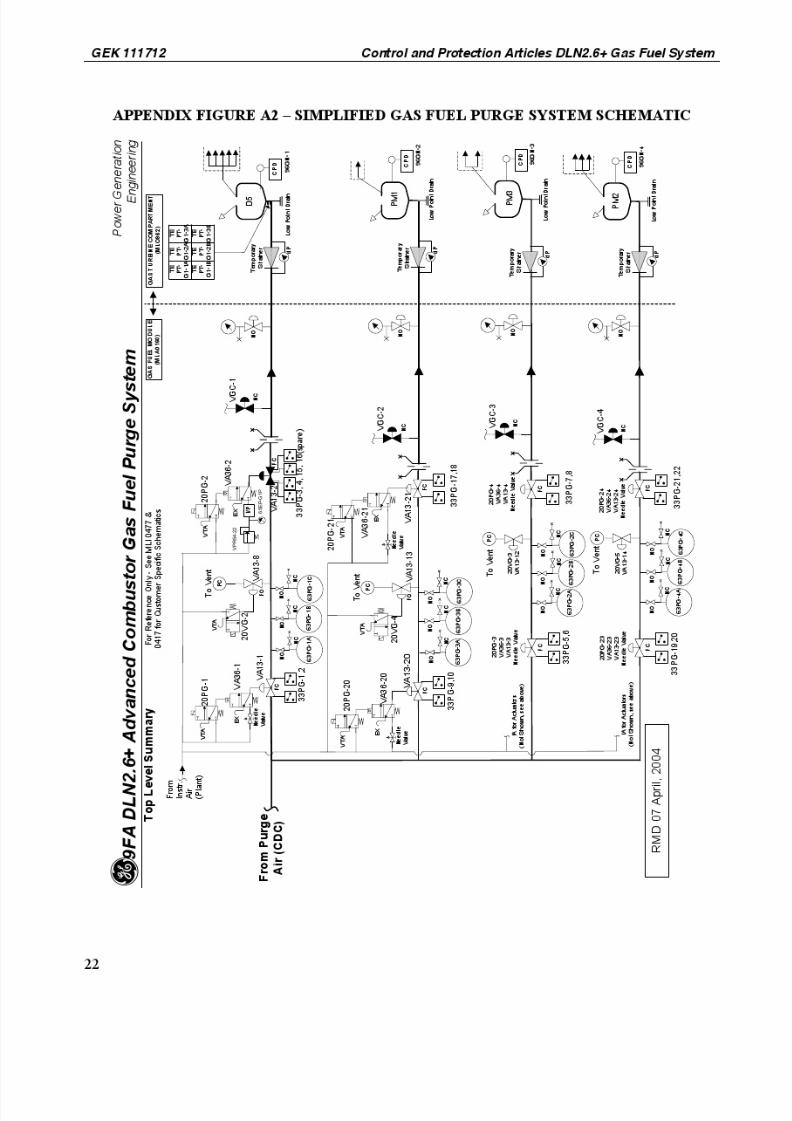
The DLN2.6+ control hardware and the control system are described in this document. See Appendix 1.
Simplified Schematic of the Gas Fuel System and Gas Purge System.
The Safer case ID for this System is EP-S-767.
II. EQUIPMENT
The Gas Fuel System consists of a gas flow metering tube, a gas fuel section of the accessory module (or
a separate gas fuel module for single shaft units), and the gas turbine on-base equipment. This section
houses both the gas fuel system, and gas fuel purge system. A brief description of the system’s overall
major components is described below. See Gas Fuel System Articles for further details.
A. Gas Flow Measurement (96FM-1)
A mass flow transmitter, 96FM-1 and Gas fuel meter tube / orifice (MG2-1) are used to measure
natural gas flow. The device, 96FM-1 operates on the principle of measuring delta pressure across the
gas fuel meter orifice, static gas pressure and gas temperature. These measured parameters establish
the mass flow when the flow area ratio (beta) is known (constant). Gas Fuel Flow is only used for
monitoring, and display in the gas turbine controls.
B. Gas Fuel Auxiliary Stop Valve (VS4-1)
The Auxiliary Stop Valve is a butterfly type isolation valve that provides the required ANSI Class VI
shutoff of the gas fuel supply. This valve is only required for units with performance heating of the
gas fuel. For units without performance heating, the Stop/Speed Ratio Valve (SRV) provides the
required ANSI Class VI shutoff capability and the Auxiliary Stop Valve is not required.
This valve is pneumatically actuated with a spring close actuator design for fail-safe operation. When
the system is pressurized or not tripped, the solenoid operated pilot valve (20VS4-1) directs
instrument air to the actuator of the aux. stop valve. The valve actuator acts against the valve spring
causing the valve to open. During a trip event the solenoid valve (20VS4-1) is de-energized which
vents the pressurized air in the Stop Valve actuator to atmosphere. The compressed spring causes the
Fuel Gas Auxiliary Stop valve to close. This valve opens during the gas turbine ignition sequence
when the turbine is started.
C. Stop/Speed Ratio Valve (VSR-1)
The SRV is a V-notch type ball valve that serves two functions. First it operates as the primary stopvalve, making it an integral part of the protection system. The SRV is tripped closed by the hydraulic
trip system via the directional trip relay VH5-1. This valve is hydraulically actuated with a spring
close actuator for fail-safe operation. An emergency trip or flame out on a normal shutdown will trip
the valve to its closed position, isolating gas fuel to the turbine. Closing the SRV can be achieved in
two ways: dumping the hydraulic trip oil to the SRV, or driving the SRV closed electrically using the
servo valve 90SR-1 with the control systems SRV position control loop. The other function of the
SRV is pressure regulation. The control system uses the SRV to regulate the pressure (P2) upstream
of the Gas Control Valves. This function is described in further detail in Section IV - Control.

8/10/2019 GEK111712 Control & Protection
http://slidepdf.com/reader/full/gek111712-control-protection 5/24
Control and Protection Articles DLN2.6+ Gas Fuel System GEK 111712
5
D. Gas Fuel Control Valves (VGC-1, VGC-2, VGC-3, VGC-4)
There are four independent Gas Control Valves (GCV’s) in the DLN2.6+ system. The GCV’s are
angle body plug valves actuated by hydraulic cylinders with a spring close actuator for fail-safe
operation. The actuator design is single acting. The plugs in the GCV’s are contoured to provide a
proportional flow area in relation to valve stroke. The GCV’s use a skirted valve disc and venturi seat
to obtain high pressure recovery. This high pressure recovery design achieves critical pressure
operation at substantially lower valve pressure drops. The result is that the flow through the GCV’s is
independent of the pressure drop across the valves and is a function of valve inlet pressure (P2) and
valve area only. The valves are positioned by the control system to maintain a percentage of the total
fuel to each of the fuel circuits. This fuel split is a function of DLN operating mode, and the
combustion reference temperature.
E. Gas Purge Block Valves (VA13-1, VA13-2, VA13-20, VA13-21, VA13-3, VA13-4, VA13-23,
VA12-24)
The gas purge block valves are a V-notch type ball valve. These valves are arranged in a double
block and bleed configuration. The actuator design for each valve is a pneumatically operated rack-
and-pinion with a fail close spring. The valves are driven open and closed using a pneumatically
operated pilot valve (VA36-1, VA36-2, VA36-20, VA36-21, VA36-3, VA36-4, VA36-23, VA36-24). These valves provide for rapid exhaust of instrument air from the actuators of the VA13 valves.
The VA36 valves are driven by a solenoid operated pilot valve (20PG-1, 20PG-2, 20PG-20, 20PG-
21, 20PG-3, 20PG-4, 20PG-23, 20PG-24) for actuation. A metering needle valve is provided on the
inlet pressure side of the pilot valves (VA36) to control the opening rate of each VA13 valve, except
for VA13-2. This valve, VA13-2, is equipped with an I/P controller, used to provide for a variable
slew rate and positioning. The opening rate of the purge valves must be slow in order to minimize
transients. Excessive megawatt and temperature transients are caused by too rapid purging of gas fuel
from the fuel manifolds into the combustion system. The purge system is designed to minimize this
effect. Each valve has two limit switches that indicate open and closed valve position and are used for
monitoring and diagnostics in the control system.
F. Gas Purge Pressure Ratio Monitoring (96GN-1, 96GN-2, 96GN-3, 96GN-4)When a gas circuit is being purged, a minimum gas purge pressure ratio must be maintained to ensure
positive airflow across all the fuel nozzles. This pressure ratio is sufficient to overcome any
combustion can-to-can pressure variation. The differential pressure transmitters measure the gas
manifold pressure relative to compressor discharge pressure. These pressures are used for monitoring
and alarm in the control system.
III. OPERATION
A. General
Gas fuel flow is controlled with the Auxiliary Stop Valve, SRV, Diffusion GCV (D5) and the Premix
GCV’s (PM1, PM3 and PM2). The SRV and the GCV’s work in conjunction to regulate the total fuel
flow delivered to the gas turbine. The GCV’s control the desired fuel flow in response to a controlsystem fuel command, Fuel Stroke Reference (FSR). The response of the fuel flow to the GCV
position commands is made linear by maintaining a predetermined pressure upstream of the GCV’s
(P2). The GCV’s upstream P2 pressure is controlled by modulating the SRV as a function of turbine
percent speed (TNH), and feedback FPG2 from the P2 pressure transducers (96FG-2A, 96FG-2B,
96FG-2C).
The DLN2.6+ Gas Fuel System has four fuel manifolds (D5, PM1, PM3 & PM2). These are
independent fuel circuits each having an individual GCV for controlling gas fuel delivery. Each

8/10/2019 GEK111712 Control & Protection
http://slidepdf.com/reader/full/gek111712-control-protection 6/24
GEK 111712 Control and Protection Articles DLN2.6+ Gas Fuel System
6
combustion chamber has six fuel nozzles arranged in a five-around-one configuration. The PM1nozzle is in the center. The five outer nozzles have a diffusion passage and a premix passage (PM3 or
PM2). The center nozzle only receives premix fuel flow. Refer to Figure 1 for the DLN2.6+ Nozzle
Arrangement.
Circuit DescriptionD5 Outer nozzle diffusion passage
PM1 Center nozzle premix passage
PM3 Premix passage on 3 outer nozzles
PM2 Premix passage on 2 outer nozzles
Each of these four gas fuel circuits requires
continuous independent control. Thus, each has a
separate manifold and control valve.
PM1
D5
PM2
D5
PM3
D5
D5
PM3
D5
PM3
Figure 1. DLN2.6+ Fuel Nozzle Arrangement
Each fuel circuit requires a certain percentage of the total fuel. The percentage of fuel to each circuit
is a function of Combustion Reference Temperature (TTRF1) and DLN operating mode. There are
six steady state DLN modes of operation: Diffusion, Sub Piloted Premix, Piloted Premix, Sub
Premix, Premix and Extended Piloted Premix (not a normal operating mode). There are also two
transient load rejection modes. All fuel is directed to the PM1 nozzle during load rejections from
Premix or Sub-Premix modes. Load rejections from all other modes will be to Sub-Piloted Premix
mode. The steady state DLN operating modes are a function of Combustion Reference Temperature
(TTRF1). Refer to Table 1 DLN2.6+ Mode Staging Diagram.
This method of staging the fuel requires individual control valves (GCV-1, GCV-2, GCV-3, andGCV-4) for each fuel circuit. In order to optimize flow split accuracy, the control valves are operated
with a critical pressure ratio. A P2 pressure value, or control valve supply pressure, is
preprogrammed into the control scheme in order to maintain this critical pressure ratio throughout the
operating range. This control method ensures pressure fluctuations downstream of the gas valvesdoes not impact flow accuracy.
During certain DLN modes of operation, some circuits will have no fuel flow scheduled. A means of
purging these stagnant circuits is required to prevent condensate from accumulating, and to minimize
the potential for auto-ignition. The gas fuel that remains in a circuit after fuel flow is commanded off
is purged into the combustion chambers when the purge is commanded on. A connection to the purge
air system is located just downstream of the gas control valves. This ensures that the entire length of
pipe and manifold is purged.

8/10/2019 GEK111712 Control & Protection
http://slidepdf.com/reader/full/gek111712-control-protection 7/24
Control and Protection Articles DLN2.6+ Gas Fuel System GEK 111712
7
Table 1. DLN2.6+ Mode Staging Diagram
MODE OPERATIONAL
RANGE
CIRCUITS
FUELED
CIRCUITS
PURGED
Diffusion (P) Ignition to
TTRF=1500
D5 None below 95%
SpeedPM1+PM2+PM3
above 95% Speed
Sub Piloted Premix
(L)
95% speed to
TTRF=2000
D5 + PM1 PM3 + PM2
Piloted Premix
(H)
TTRF=1500 to 2300 D5 + PM1 + PM3 PM2
Sub Premix (M) TTRF=1900 to 2300 PM1 + PM3 D5 + PM2
Premix (B) TTRF=2150 to BaseLoad
PM1 + PM3 + PM2 D5
Extended Piloted
Premix (A)
TTRF=2150 to Base
Load
D5 + PM1 + PM3 +
PM2
None
Load Rejection (I) Transient from
Premix or Sub-Premix
Modes
PM1 Premix: D5
Sub-Premix:
D5+PM2
Load Rejection (P or
L)
Transient from all
other Modes
D5 or D5 + PM1 (see
Note 1)
None
NOTES
1. Load Rejection to normal Full Speed No Load (FSNL) mode, which will be
either Diffusion Mode (D5 fueled) or Sub Piloted Premix Mode (D5 + PM1
fueled).
2. The unit will be load limited in each mode (except Premix and Ext. Piloted
Premix) at the upper end of the design ranges defined in this table.
B. Pre-start Conditions
Prior to unit start, the following start conditions must be satisfied for the Gas Fuel and Gas Purge
System.
1. Gas supply pressure within limits.
2. Gas module ventilation pressure normal.
3. Servo currents within limits.
4. P2 pressure feedback signal within limits.
5. Control valves track commands within limits.
6. Valve position feedback within limits.
7. All GCV’s closed.

8/10/2019 GEK111712 Control & Protection
http://slidepdf.com/reader/full/gek111712-control-protection 8/24
GEK 111712 Control and Protection Articles DLN2.6+ Gas Fuel System
8
8. Auxiliary Stop Valve and SRV cavity pressure normal.
9. No gas purge valve position faults.
During the start period the above conditions are continuously checked by the control system If any
condition is not satisfied the unit will not be allowed to start.
Prior to starting the gas fuel system, the following systems must be operating:
• Gas fuel compressors, when pipe line supply pressure is insufficient
• Instrument air system
Pre-Ignition P2 Pressure High Start Inhibit
The Pre-Ignition P2 Pressure High protection sequencing makes sure that the P2 cavity is clear of any pressure with the vent valve open, just prior to light-off. If the P2 pressure (FPG2) exceeds a
specified increasing pressure for a determined amount of seconds prior to firing permissive (L2TVZ),
a pre-ignition trip or Start Inhibit (L4PRETX) and alarm will occur.
C. Startup and Loading Operation
Gas Purge Valve Test
At the very beginning of startup the gas purge valves are tested automatically by the controls to verify
that slew times are within specification. All valves are cycled open and closed with the resultant time
to complete each operation for each valve being measured. An alarm signal is generated for any valve
that does not cycle within the allotted time frame. Alarm signals are generated for both open and
close time violations for each valve. The turbine will not start cranking if any valve fails to pass the
test. Once the gas purge valve test is complete, the gas turbine starts to crank.
Gas Fuel Leak Test
The Gas Leak Test will test the SRV and GCV’s for high leakage rates upon startup and shutdown by
monitoring the pressure in the P2 cavity. The tests will take place when the turbine starts purging
speed for the startup test and just after the turbine is shutdown for the shutdown test. Once either of
these enable commands have been met, the test will start. The Gas Leak Test is composed of four (4)
steps. Refer to Figure 2 Gas Leak Test Function Block Diagram.
Test A:
Test A will monitor the leakage across the SRV. The Auxiliary Stop Valve will be commanded open,
the Fuel Gas Vent Solenoid valve will be commanded closed (20VG-1), and the Fuel Gas Trip
Solenoid will be opened (20FG-1) to allow the trip system piping to fill up with oil for the next phase
of testing. If the leakage across the SRV is excessive and the P2 cavity pressure rises aboveK86GLTA pressure in K86GLT1 seconds, turbine startup will be inhibited and the machine will
shutdown.
Open SRV:
Once Test A has been passed, the SRV will be commanded open by forcing the SRV
pressure offset to a large pressure value for K86GLT2 seconds to ensure that the P2 cavity
has been pressurized to full line (supply) pressure. The SRV and the Aux Stop Valve will

8/10/2019 GEK111712 Control & Protection
http://slidepdf.com/reader/full/gek111712-control-protection 9/24
Control and Protection Articles DLN2.6+ Gas Fuel System GEK 111712
9
then be commanded closed again and Test B will start. When K86GLT2 times out, the P1 pressure and P2 pressure will be latched and compared to each other. If the difference
between the two pressures is greater than K96FG_DIFF an alarm will notify the controller.
Test B:
Test B will monitor the P2 pressure and make sure that the GCV’s or Vent Valve is not leakingexcessively. If the P2 pressure drops below more than K86GLTB psi after K86GLT3 seconds, the
turbine will start inhibit and latch in an alarm. If Test B passes after K86GLT3 seconds, the vent will
open and the pressure will drain out of the P2 cavity. If there is no Aux Stop Valve, the test is over,
and the turbine will proceed with normal operation.
Relieve Pressure:
If the Aux Stop Valve is required for the system, the test will wait 5 seconds to ensure that all valves
have been returned to normal state. The SRV will then be opened again to relieve any pressure that
has been built up between that Aux Stop Valve and the SRV during the tests. Once this pressure has
been drained, the SRV will close and the test will be completed.
NOTE
If the SRV does not return to its normal sealed position when the test times out, the
P2 Pre-Ignition Trip will alarm and inhibit startup.

8/10/2019 GEK111712 Control & Protection
http://slidepdf.com/reader/full/gek111712-control-protection 10/24
GEK 111712 Control and Protection Articles DLN2.6+ Gas Fuel System
10
time
Test A Test B
K86GLT1 K86GLT2 K86GLT3
P1 pressure
Test B Limit
Test A Limit
P2 pressure with
vent open
Test A Fail
Test B Fail
P2 Pressure
vent valve
20VG-1aux stop vlv
VS4-1
SRV
GCV(s)
open
closedopen
closed
open
closed
open
closed
FG Trip
Solenoid
20FG-1
open
closed
K86GLT4
K86GLT5 K86GLT6
if Aux Stop Valve
Option
relieve
pressureopen SRV
Figure 2. Gas Fuel Leak Test Function Block Diagram

8/10/2019 GEK111712 Control & Protection
http://slidepdf.com/reader/full/gek111712-control-protection 11/24
Control and Protection Articles DLN2.6+ Gas Fuel System GEK 111712
11
Valve Test Condition Aux
Stop Vlv
SRV Vent
Vlv
GCVs Pass Criteria Test Time Action
GSRV Unit Start and
Normal Shutdown *Open Closed Closed Closed P2 < 100 PSIG 30 sec
Startup
Lockout
FPG2
x-mitters
Unit Start and
Normal Shutdown *Open Open Closed Closed
ABS (P1-P2) <
20 PSI1 sec Alarm
GCV Unit Start and Normal Shutdown *
Closed Closed Closed ClosedP2 > P1 – 150
PSI30 sec
Startup
Lockout
Venting Unit Start and
Normal Shutdown *Closed Closed Open Closed P2 < 6 psi
After vent
timer
Startup
Lockout
Post Ignition P2 Pressure High and Low Trip
After firing and before warm-up complete, the P2 pressure is monitored to ensure that it is within a
predetermined pressure range. The desired unit P2 pressure during warm-up is calculated to achieve
the unit pressure range. If the pressure is lower or higher than a specified tolerance for a given time
frame, the unit will alarm and trip.
Start
The gas turbine is started in D5 Diffusion mode. When the unit reaches firing speed, the SRV (VSR-
1) and the D5 Diffusion GCV (VGC-1) servo controls are enabled. The P2 cavity vent valve (VA13-
15) closes. The SRV opens to control P2 pressure to its setpoint, and the D5 GCV (VGC-1) opens to
the ignition setpoint.
After flame is established and the turbine warm-up cycle is complete, the unit accelerates to Full
Speed No Load (FSNL) in Diffusion mode. At 95% speed, the unit transfers to Sub Piloted Premix
mode (SPPM). The control code also has the capability of delaying the Diffusion to SPPM transfer
up to TTRF1 levels of 1500 degrees F. At the SPPM transfer point, the PM1 GCV (VGC-2) is
enabled open to the Prefill position. After Prefill is complete, the PM1 GCV (VGC-2) is commanded
to a target fuel split. The purge system will be enabled 60 seconds after the unit reaches 95% speed.
Once the purge system is enabled in SPPM mode, the PM3 purge valves will open. After an 11
second delay, the PM2 purge valves will open, admitting compressor discharge air into the gas
manifolds. If Diffusion mode is utilized above 95% speed, the purge on sequence will be PM1, then
PM3, then PM2 (with 11 second delays).
At rated speed, the unit is synchronized and the breaker is closed. The unit load increases towards full
load. The fuel system remains in Sub Piloted Premix mode, until the first combustion reference
temperature (TTRF1) switch point. At this switch point, the fuel system transfers to Piloted Premix
(PPM) mode. This first switch point occurs between TTRF1=1500 and TTRF1=2000.
At the Piloted Premix (PPM) switch point, the PM3 circuit purge valves (VA13-3, VA13-4) are
commanded closed. When these valves are confirmed closed, the PM3 GCV (VGC-3) is enabled
open to the Prefill position. After Prefill is complete, the PM3 GCV (VGC-3) is commanded to atarget fuel split. The fuel split schedule for each DLN mode is a function of combustion reference
temperature (TTRF1). The unit is now in Piloted Premix (PPM) Steady State mode.
At the second combustion reference temperature (TTRF1) switch point, the fuel system transfers to
Sub Premix mode. This switch point occurs between TTRF1=1900 and TTRF1=2300. The D5 GCV
(VGC-1) is commanded closed and confirmed closed and the D5 circuit purge valves (VA13-1,
VA13-2) are commanded open, admitting compressor discharge air into the gas manifold. The unit is
now in Sub Premix (SPM) Steady State mode.
8/10/2019 GEK111712 Control & Protection
http://slidepdf.com/reader/full/gek111712-control-protection 12/24
GEK 111712 Control and Protection Articles DLN2.6+ Gas Fuel System
12
At the third combustion reference temperature (TTRF1) switch point, the fuel system transfers toPremix mode. This switch point occurs between TTRF1=2150 and TTRF1=2300. The PM2 circuit
purge valves (VA13-23, VA13-24)) are commanded closed. Once confirmed closed, the PM2 GCV
(VGC-4) is enabled open to the Prefill position. After Prefill is complete, the PM2 GCV (VGC-4) is
commanded to a target fuel split. The unit is now in Premix (PM) Steady State mode. The unit
continues to operate in Premix mode up to Base load.
A backup mode (Extended Piloted Premix) is also available for testing, commissioning and fault
accommodation. This mode provides fuel to all four fuel circuits. Ext.PPM mode can be enabled by a
pushbutton on the HMI screen. If this option is selected, the unit will load using SPPM, PPM, and
Ext.PPM modes, and will not use SPM or PM modes. Ext.PPM mode is also used if a D5 purge fault
occurs while in Premix mode (see section V).
The shutdown sequence of the fuel system is the reverse of the startup and otherwise similar. During
shutdown the unit transfers to SPM, PPM, SPPM and then to Diffusion mode, down to flame out at
approximately 17% speed. At approximately 94% turbine speed the gas purge valves are closed.
After flame out the hydraulic trip system is de-energized and the SRV and GCV’s close. The P2
cavity vent valve opens.
IV. CONTROL
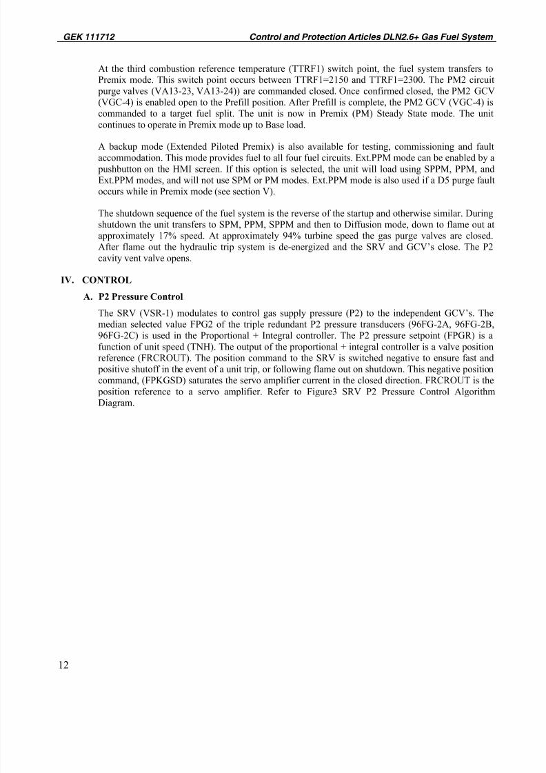
A. P2 Pressure Control
The SRV (VSR-1) modulates to control gas supply pressure (P2) to the independent GCV’s. The
median selected value FPG2 of the triple redundant P2 pressure transducers (96FG-2A, 96FG-2B,
96FG-2C) is used in the Proportional + Integral controller. The P2 pressure setpoint (FPGR) is a
function of unit speed (TNH). The output of the proportional + integral controller is a valve position
reference (FRCROUT). The position command to the SRV is switched negative to ensure fast and
positive shutoff in the event of a unit trip, or following flame out on shutdown. This negative position
command, (FPKGSD) saturates the servo amplifier current in the closed direction. FRCROUT is the
position reference to a servo amplifier. Refer to Figure3 SRV P2 Pressure Control Algorithm
Diagram.

8/10/2019 GEK111712 Control & Protection
http://slidepdf.com/reader/full/gek111712-control-protection 13/24
Control and Protection Articles DLN2.6+ Gas Fuel System GEK 111712
13
P2 Reference =
Speed(TNH) *
Gain (FPKGNG)
+ Offset(FPKGNO)
Speed
(TNH)
Proportional
+Integral
Control
GFPRGR
Application Code Control Algorithm
MED
Select
96FG-2A
96FG-2B
96FG-2C
Signal Space
Signal SpaceOutput
Signal SpaceInputs
FAGR
Inputs
FRCROUT
SRV Control
Fault LogicFSGR
FPG2
(Not Tracking)
Protection
Permissives
True
False
Shutdown
Command
L3GRV
FPKGSD
FRCROUT
P2 Pressure
Fault Logic
(Not Tracking)
Figure 3. SRV P2 Pressure Control Algorithm Diagram
The P2 pressure setpoint is lower at low speed, in order to provide better flow control at low fuelflow. Thus, the GCV does not have to reduce full line pressure, allowing the GCV to open further,
providing for better low flow control. The P2 pressure increases linearly to the 100% rated speed
pressure setpoint. The pressure downstream of the GCV’s (P3) at maximum fuel flow is used to
determine the rated speed pressure setpoint. The downstream pressure (P3) is a function of gas
turbine compressor pressure ratio, total flow, flow split settings and fuel nozzle size. The rated speed
pressure setpoint must be sufficient to maintain critical pressure drop across the GCV’s at max fuel
flow. The controlled P2 pressure and the critical pressure drop design of the gas control valves
ensures that the percentage valve stroke is proportional to percentage fuel flow.
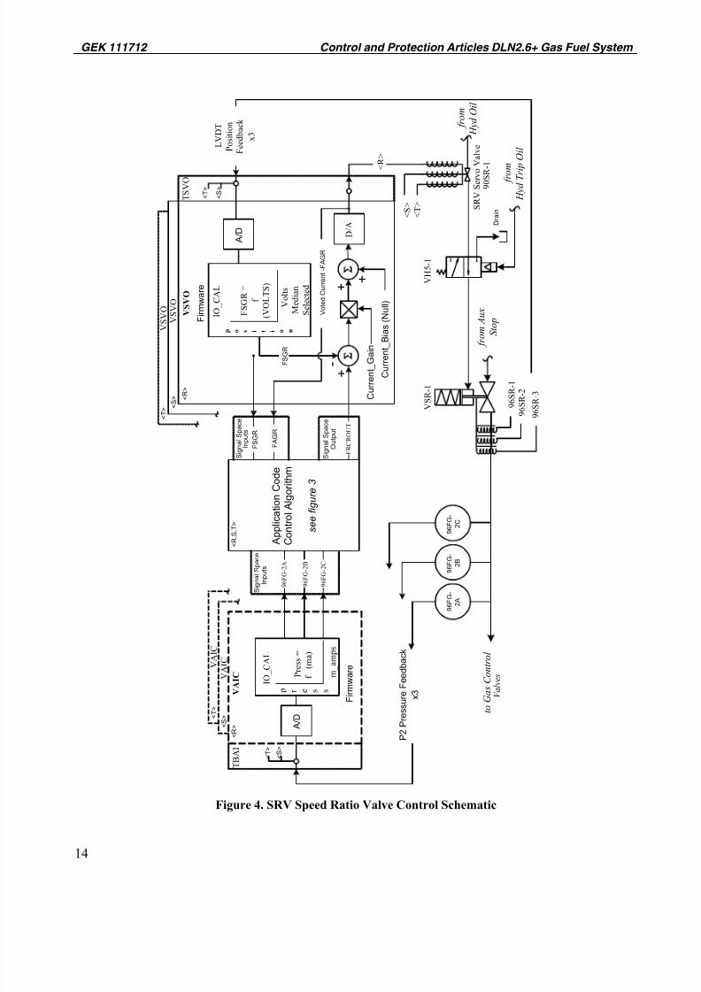
The control of the SRV is accomplished by using an inner and outer loop. The SRV’s position control
loop is the inner control loop. The pressure control loop is the outer control loop. Three LVDT’s
sense SRV stem position and their outputs are returned to each channel <R,S,T> of the control
system. The error between the position command FRCROUT and the position feedback FSGR then
becomes the input to the servo amplifier. The servo amplifier drives the servo valve in the direction
required to decrease the position error. A null current bias is applied to the amplified signal in order
to overcome the fail safe servo spring bias. Refer to Figure 4 SRV Control Schematic.
8/10/2019 GEK111712 Control & Protection
http://slidepdf.com/reader/full/gek111712-control-protection 14/24
GEK 111712 Control and Protection Articles DLN2.6+ Gas Fuel System
14
f r o m
H y d O i l
V A I C
I O_
C A L
P r e s s =
f
( m a
)
V S V O
+ -
9 6 F G -
2 A
9 6 F G -
2 B
9 6 F G
-
2 C
p r e s s
m_
a m p s
< T > S
R V S e r v o
V a
l v e
9 0 S R
- 1
D / A
C u r r e n t_ G a i n
C u r r e n t_
B i a s ( N u l l )
f r o m A u x
S t o p
V S R - 1
9 6 S R - 2
9 6 S R - 1
t o G a
s C o n t r o l
V a l v e s
F R C R O U T
A p p l i c
a t i o n C o d e
C o n t r o l A l g o r i t h m
s e e f i g u r e 3
9 6 F G - 2
A
9 6 F G - 2
B
9 6 F G - 2
C
P 2 P r e s s u r e
F e e d b a c k
x 3
F i r m w a r e
T B A I
A / D
S i g n a l S p a c e
I n p u t s
S i g n a l S p a c e
O u t p u t
I O_
C A L
F S G R =
f
( V O L T S )
M e
d i a n
S e l e c
t e d
p o s i t i o n
V o
l t s + +
S i g n a l S p a c e
I n p u t s
A / D
F S G R
F S G R
< S >
F i r m w a r e
T S V O
< R >
V o t e d C u r r e n t - F A G R
F A G R
L V D T
P o s i t i o n
F e e
d b a c
k
x 3
D r a i n
f r o m
H y d T r i p O i l
V H 5 - 1
< R , S , T >
< R >
< S >
< T >
V S V O
V S V O
< S >
< T >
< R > <
S > <
T >
V A I C
V A I C
< S >
< T >
9 6 S R - 3
Figure 4. SRV Speed Ratio Valve Control Schematic

8/10/2019 GEK111712 Control & Protection
http://slidepdf.com/reader/full/gek111712-control-protection 15/24
Control and Protection Articles DLN2.6+ Gas Fuel System GEK 111712
15
B. Gas Flow and Split Control
The gas control valves (VGC-1, VGC-2, VGC-3, VGC-4) modulate to control fuel flow and split
between the four fuel circuits. The percentage of fuel to each circuit is a function of Combustion
Reference Temperature, and DLN operating mode. The control system’s fuel command, FSR, is the
percentage of maximum fuel flow required by the control system to maintain either speed/load, or
another setpoint. The combined flow references used to position the four independent control valves
is proportional to FSR. FSR is divided into two parts, which make up the fuel split setpoint, FSR1
and FSR2. FSR1 is the percentage of maximum fuel flow required from the Liquid Fuel System, and
FSR2 is the percentage of maximum fuel flow required from the Gas Fuel System. FX1 is the fuel-
split command. A fuel-split command FX1 of 1.0 is equal to 100 % liquid fuel FSR1, and a fuel-split
command FX1 of 0.0 is equal to 100% gas fuel FSR2. For a gas only machine FSR2 is always equal
to FSR.
FSR2 is again divided into four parts for the four independent control valves. FQRG1, FQRG2,
FQRG3, and FQRG4 are the percentage of FSR2 to be sent to the D5 Diffusion gas fuel nozzles, the
PM1 Premix center gas fuel nozzles, PM3Premix outer gas fuel nozzles, and PM2 Premix outer gas
fuel nozzles. FSRG1OUT, FSRG2OUT, FSRG3OUT, and FSRG4OUT are the final output signals to
the position loop regulators after the shutdown position select logic. The position commands to each
valve are switched negative to ensure fast and positive shutoff in the event of a unit trip, or following
flame out on shutdown. This negative position command, FSKSHUT saturates the servo amplifier
current in the closed direction. FSRG1OUT is the position reference to a servo amplifier, which
drives the coils of the D5 Diffusion GCV. FSRG2OUT is the position reference to a servo amplifier,
which drives the coils of the PM1 Premix GCV. FSRG3OUT is the position reference to a servo
amplifier, which drives the coils of the PM3 Premix GCV. FSRG4OUT is the position reference to a
servo amplifier, which drives the coils of the PM2 Premix GCV. Refer to Figure 5 GCV Control
Algorithm Diagram.
FSR
MIN Select
Application Code Control Algorithm
Signal SpaceOutput
Signal SpaceInputs
FAGn
FSRGnOUT
GCV ControlFault Logic
FSGn
FSR
(Not Tracking)
Protection
Permissives
True
False
Shutdown
Command
L3GnX
FSKSHUT
FSRGnOUT
Rate
Limit
Combustion Ref Temp
(TTRF)
DLN Split ScheduleDLN Mode
Selection Logic
FX1
FSR2
+
-
Fuel Split Command
FSR1
Figure 5. GCV Control Algorithm Diagram

8/10/2019 GEK111712 Control & Protection
http://slidepdf.com/reader/full/gek111712-control-protection 16/24
GEK 111712 Control and Protection Articles DLN2.6+ Gas Fuel System
16
Three LVDT’s sense the GCV’s stem position and their outputs are returned to each channel of thecontrol system. The error between the position command and the position feedback then becomes the
input to the servo amplifiers. The servo amplifiers drive the servo valves in the direction required to
decrease the position error. A null current bias is applied to the amplified signal in order to overcome
the fail safe servo spring bias. Refer to Figure 6 GCV Control Schematic.
from
Hyd Oil
VSVO
+-
SRV Servo Valve
65GC-n
D/A
Current_GainCurrent_Bias (Null)
from SRV
VGC-n
96GC-m
96GC-n
to Gas
Manifolds
FSRGnOUT
Application Code
Control Algorithm
see figure 5
Signal SpaceOutput
IO_CAL
FSGn =
f (VOLTS)
Median Selected
p
o
s
i
t
i
o
n Volts
+
+
Signal SpaceInputs
A/D
FSGn
FSGn
<S>
Firmware
TSVO
<R>
Voted Current - FAGn
FAGn
LVDT
Position
Feedback
x3
<R>
<S><T>
VSVOVSVO
<S>
<T>
<T>
96GC-o
VGC-n VGC-1 VGC-2 VGC-3 VGC-4
65GC-n 65GC-1 65GC-2 65GC-3 65GC-496GC-m 96GC-1 96GC-4 96GC-7 96GC-10
96GC-n 96GC-2 96GC-5 96GC-8 96GC-11
96GC-o 96GC-3 96GC-6 96GC-9 96GC-12
FSG-n FSG-1 FSG-2 FSG-3 FSG-4
FAG-n FAG-1 FAG-2 FAG-3 FAG-4
FSRGnOUT FSRG1OUT FSRG2OUT FSRG3OUT FSRG4OUT
GCV Insturmentation and Control Signals
<R>
Figure 6. GCV Control Schematic
C. Gas Fuel Temperature Compensation
Redundant gas temperature thermocouples (FTG-1A, -1B, -2A, -2B) measure supply temperature at
the auxiliary stop valve inlet. The median selected value is used in the controls to compensate for
varying gas supply. In order to maintain consistent fuel flow during open loop fuel control, acorrection factor is applied to the control valves fuel command. This correction factor is a function of
the fuel temperature deviation from nominal design temperature. All open loop fuel control setpoints
are set for the nominal design temperature. The correction factor increases or decreases the fuel
stroke command in order to provide the target mass flow with changing fuel temperature.

8/10/2019 GEK111712 Control & Protection
http://slidepdf.com/reader/full/gek111712-control-protection 17/24
Control and Protection Articles DLN2.6+ Gas Fuel System GEK 111712
17
D. Gas Purge Control
Purge air flow is controlled by purge valves (VA13-nn) arranged in a double block and bleed
configuration. The purge system is designed in an independent flow path scheme. The diffusion
purge flow path is controlled by two purge valves (VA13-1 and VA13-2). The PM1 purge flow path
is controlled by two valves (VA13-20 and VA13-21). The PM3 purge flow path is controlled by two
valves (VA13-3 and VA13-4). The PM2 purge flow path is controlled by two valves (VA13-23 and
VA13-24). Solenoid valves (20PG-nn) pneumatically actuate the purge valves open or closed.
The purge valve actuation system is designed to control the rate at which fuel is purged into the
combustors. A manual needle valve provides a means of adjusting the opening rate for all of the
purge valves, except for VA13-2. An I/P controller is used for controlling the position of VA13-2
(gas-side Diffusion purge valve). The needle valves for the air-side purge valves are set to open the
purge valves quickly, and the needle valves for the gas-side purge valves are set to open the purgevalves at a slower rate. The I/P controller on VA13-2 provides additional flexibility for valve opening
rates and allows for steady state positioning at mid-stroke levels. A quick exhaust valve (VA36-nn) is
utilized for rapid closure of the purge valves. Refer to gas fuel purge schematic (MLI-0477) for
settings. The control system energizes the solenoid valves in order to open the purge valves. When a
solenoid valve is energized, pilot air is supplied to the quick exhaust valve (VA36-nn) which opens,
allowing air to flow to the purge valve (VA13-nn) actuator. The purge valves open at a rate set by the
metering needle valve (or VA13-2 I/P controller) in the air supply line of the VA36 valve, and allow
purge air to flow to the gas manifold. A purge valve test is performed automatically by the controls at
the beginning of machine startup to verify that valve open/close slew times are within specification.
Refer to Startup and Shutdown Control & Protection Article for further information.
The purge valves provide different functions depending on the mode of operation. While operating in
purge mode, they provide the flow control to the gas manifolds. While operating in blocking mode
these valves provide a double block and bleed isolation of fuel from the purge system. An inter-cavity
vent valve (20VG-nn) is located between the two purge valves which provides a block and bleed
system. In the event that fuel leaks past the gas purge valves in either direction and becomes too
excessive for the vent valve to bleed off, pressure switches will sense the cavity pressure, and an
appropriate action will be executed as described in Section V Protection.
V. PROTECTION
The following key describes the protective actions initiated by the control system for the gas fuel and gas
fuel purge systems.
Key: A = Alarm
SI = Start Inhibit
LO = Lockout Loading & DLN Mode Transfers
RB = Normal load runback until condition clears
FRB = Fast load runback until condition clears
PIT = Pre-ignition Trip (No Trip after Warmup complete)SD = Unit Shutdown
STP = Soft trip
TP = Trip
OFF = System is turned off
PBR = Push button reset

8/10/2019 GEK111712 Control & Protection
http://slidepdf.com/reader/full/gek111712-control-protection 18/24
GEK 111712 Control and Protection Articles DLN2.6+ Gas Fuel System
18
A. P2 Pressure Control Protection and SRV Position Control Protection
Alarms and protective actions are initiated by the control system to protect the gas turbine and
combustion hardware from a loss of fuel control. The following table illustrates these protective
features.
In addition to P2 pressure protection, valve position fault protection is provided in the control system.If the SRV is not tracking position commands, it will result in DLN split errors, loss of load control,
and potential trips. The SRV has triple redundant position feedback transducers (LVDT’s).
Table 2. Protective levels and actions for the Gas Fuel System – Gas Pressure
Test Action Description
SRV Not
TrackingA, TP, PBR
Alarm if the SRV valve actual position is not following
specified position reference until warm-up is complete.
Trip if the SRV valve actual position is not followingspecified position reference until warm-up is complete.
Pre-Ignition
P2 Check A, SI, TP, PBR
If the P2 pressure exceeds specifications for
predetermined seconds before firing permissive isreached.
Post Ignition
P2 CheckA, TP, PBR
If the P2 Pressure exceeds specifications for
predetermined seconds between firing permissive and
warmup complete, alarm and trip the unit. If the P2
pressure falls below specified pressure for
predetermined seconds between firing permissive and
warmup complete, alarm and trip the unit.
Running P2Check
A, RB
If the P2 pressure falls below specified limit for
predetermined seconds, alarm and run the unit back to
safe mode.
Bottle Test A, SI, TP, PBR
If the P2 pressure rises above specified pressure during
test A, start inhibit. If the P2 pressure dips belowspecified pressure during test B, start inhibit. If the P1
pressure and P2 pressure transmitters do not read within
specified differential pressure of each other, alarm the
controller.
Low fuel
pressureA, SI, RM
Low fuel module inlet pressure (P1) or gas control valve
inlet pressure (P2) results in an alarm and unload to
SPPM mode for gas-only units. Dual fuel units willalarm and initiate a transfer to liquid fuel operation.
B. Fuel Temperature and Modified Wobbe Index Protection
In order to protect the gas fuel system hardware, triple sensors at the gas module inlet monitor fuel
temperature. High fuel temperature readings will result in the following actions:
• High temperature: Alarm
• High-High temperature: Shutdown performance heater
• High-High-High temperature: Shutdown turbine
In order to protect against combustor damage, the unit is not allowed to operate above a specified
TTRF1 level (currently set at 1900 F) if fuel properties are outside of the design Modified Wobbe

8/10/2019 GEK111712 Control & Protection
http://slidepdf.com/reader/full/gek111712-control-protection 19/24
Control and Protection Articles DLN2.6+ Gas Fuel System GEK 111712
19
Index (MWI) by more than 5%. MWI is calculated based on site-specific fuel properties and fueltemperature. If the control detects MWI is outside of limits, operation will be limited to the specified
TTRF1 level. If the unit is already operating above the specified TTRF1 level when the MWI fault
occurs, the control system will unload the unit.
C. Independent Flow Path Purge Protection
Alarms and protective actions are initiated by the control system to protect the purge system and
combustion hardware from loss of purge or failure to block gas fuel from entering the purge system.Failure to purge fuel from unused fuel circuits poses a risk of auto-ignition, formation of condensate
in the piping or fuel nozzle back flow. A loss of fuel blocking can result in a hazardous condition
where gas fuel is present in the purge system, with the potential for fuel ignition. Multiple sensors are
used in the purge fault detection strategy, including open and closed limit switches on each valve, as
well as purge cavity pressure switches. A low pressure while purging indicates a loss of purge faultand a high pressure while blocking indicates a loss of blocking fault. The controls utilizes all of these
sensors in the protective strategy in order to provide single fault tolerant protection. The following
table illustrates these protective actions. Refer to Table 7 Independent Flow Path Purge Protection for
more information.

8/10/2019 GEK111712 Control & Protection
http://slidepdf.com/reader/full/gek111712-control-protection 20/24
GEK 111712 Control and Protection Articles DLN2.6+ Gas Fuel System
20
Table 3. Independent Flow Path Purge Protection
EVENT FAULT SETPOINT ACTIONLoss of Purge
(LOP) • Single limit switch
indicating out of position
or a single pressure switch
indicating low
< 50 psig
Alarm
• Both limit switches out of
position on a single valve
(double fault) OR
• Voted low pressure OR
• Combination of two: valve
limit switches or limit
switch & pressure fault
< 50 psig • Alarm.
• Lockout Purge to faulted circuit.
• D5 Purge Fault: Lockout PM and
SPM modes (immediate transfer
to Ext.PPM or PPM)
• PM1, PM3 or PM2 Fault: Lockout
mode transfers to DLN modes that
will add fuel to faulted circuit if
the fault persists for 15 minutes.Low D5 Purge
Air
Temperature
• D5 temperature sensors
(median-select) indicate
low temperature with D5 purge commanded on.
< 270 deg. F for 10
minutes. Alarm
• D5 temperature sensors
(median-select) indicatelow temperature with D5
purge commanded on.
< 240 deg. F for 15minutes
• Alarm.
• Lockout D5 purge.
• Lockout PM and and SPM modes
(immediate transfer to Ext.PPM or
PPM)
Loss of
Blocking
(LOB)
• Single limit switch
indicating out of position
or a single pressure switch
indicating high
> 50 psig
Alarm, Pre-Ignition Trip.
•
Limit switch double faulton a single valve OR
• Combination of two: valve
limit switches or limit
switch & pressure fault
> 50 psig Shutdown
• Voted high pressure OR
• Both limit switches on a
single valve out of position
plus any other single valve
limit switch or pressure
fault OR
• Three single faults in a row
(VA13-1 limit switch fault; pressure switch fault;
VA13-2 limit switch fault)
> 50 psig Trip
Low purge
pressure ratio
• Low purge pressure sensed
at manifold
< 0.94 Ratio Alarm
Consult the Control Specification for detailed adjustments and settings of the gas fuel and gas fuel
purge systems.
Consult Device Summary for detailed device settings and calibration.
8/10/2019 GEK111712 Control & Protection
http://slidepdf.com/reader/full/gek111712-control-protection 21/24
8/10/2019 GEK111712 Control & Protection
http://slidepdf.com/reader/full/gek111712-control-protection 22/24
8/10/2019 GEK111712 Control & Protection
http://slidepdf.com/reader/full/gek111712-control-protection 23/24
Control and Protection Articles DLN2.6+ Gas Fuel System GEK 111712
23
THIS PAGE INTENTIONALLY LEFT BLANK.

8/10/2019 GEK111712 Control & Protection
http://slidepdf.com/reader/full/gek111712-control-protection 24/24
GEK 111712 Control and Protection Articles DLN2.6+ Gas Fuel System
g GE EnergyGeneral Electric Companywww.gepower.com