Embed Size (px)
Citation preview

File No. S360-1S Order No. GC22-6820-12
Systems Reference Library
IBM System/360 Installation Manual-Physical Planning

Preface
This manual contains information necessary for planning the physical installation of the IBM System/360. It includes floor planning information, as well as electrical, environmental, and structural requirements. Detailed cable charts are also provided. In addition, the manual contains suggestions for planning an efficient and a pleasant installation.
The customer, in planning his installation, should make such arrangements as he deems necessary for the services of professional consultants. The installation must meet local and national code requirements.
The physical planning requirements of the system are subject to modification by engineering developments.
Machine specifications in this manual are for those units unique to IBM System/360. For information pertaining to machines used on both IBM System/360 and System/370, refer to IBM Systemj370 Installation Manual-Physical Planning, GC22-7004.
Thirteenth Edition (February 1974) This is a major revision of GC22-6820-11, making it obsolete. In 'addition Technical Newsletter GN22-Q441 has been incorporated in the base manual, making it obsolete. Because significant changes have been made throughout the manual, it should be reviewed in its entirety. Information pertinent to IBM System/360 system models and those machines that can be used only on System/360 is included in this manual. Before using this publication in connection with the installation and operation of IBM equipment, refer to the IBM System/360 and System/370 Bibliography, GA22-6822, for editions that are applicable and current.
Requests for copies of IBM publications should be made to your IBM representative or to the IBM branch office serving your locality.
This manual has been . prepared by the IBM System Products Division, Product Publications, Dept. B98, PO Box 390, Poughkeepsie, .N.Y. 12602. A form for readers' comments is provided at the back 'of this publication. If the form has been removed, comments may be sent to the above address. Comments become the property of IBM.
©Copyright International Business Machines Corporation 1970, 1972, 1974

Section 1. Preinstallation Planning . Schedule. BUILDING REQUIREMENTS Space and Layout Requirements System Layout . Floor Construction Furniture Acoustical Treatment of C9mputer Room Lighting. . Vibration AIR CONDITIONING Temperature and Humidity Design Criteria Machine Operating Limits Air Filtration
Mechanical Air Filter Electrostatic Plate Filter
Temperature and Humidity Recording Instruments. AIR DISTRIBUTION AND TYPES OF SYSTEMS . Single Duct (Overhead System) Underfloor System . Two Duct (Two Air Conditioning Unit System) Two Duct (Single Air Conditioning Unit System) POWER REQUIREMENTS Voltage Limits . Frequency Limits Line-to-Line Voltage Imbalance Harmonic Content . POWER DISTRIBUTION SYSTEM Primary Computer Power Service Branch Circuits Grounding Phase Rotation Emergency Power-Qff Controls, Lightning Protection Convenience Outlets Primary Power Problem Areas SAFETY AND FIRE PRECAUTIONS Computer Location Fire Prevention Considerations Type of Fire Prevention Equipment in a Computer Area Data Storage Supporting Facilities
Air Conditioning Systems Electrical Systems .
Preplanning to Continue an Operation in an Emergency General Precautions and Personnel Training Additional Reference Material STORAGE OF TAPE, DISK PACK, DISK CARTRIDGE,
AND DATA CELL PRIORITY . Input/Output Priority SeqlJence
Device Wait (Critical Time) CABLES. Cables Supplied .
Cables Related to Initial Installations Other Cable Requests .
FIELD ENGINEERING SUPPORT FACILITIES CE Room and Test Area Furniture and Fixtures RETAIN/370 Services . Basic Storage Module (BSM) Analyzer
1.1 1.1 1.2 1.2 1.2 1.3 1.4 1.4 1.6 1.6 1.7 1.7 1.7 1.8 1.8 1.8 1.8 1.9 1.9 1.9 1.9 1.9 1.10 1.10 1.10 1.10 1.10 1.10 1.10 1.10 1.11 1.11 1.11 1.11 1.11 1.11 1.13 1.13 1.13 1.13 1.13 1.14 1.14 1.14 1.14 1.14 1.14
1.15 1.16 1.16 1.16 1.17 1.17 1.17 1.17 1.18 1.18 1.18 1.18 1.18
Contents
SYSTEM/360 AND SYSTEM/370 FIELD ENGINEERING FURNITURE AND TEST EQUIPMENT 1.19
STANDARD SYMBOLS 1.20 STANDARD SPECIFICATIONS 1.21 Shipping Dimensions 1.21 Environmental Specifications 1.21 Metric Conversions . 1.21 Manufacturers of Plugs, Receptacles, and Connectors 1.21 Abbreviations and Definitions . 1.22
Section 2. System Specifications and Cabling Schematics
System/360 Model 22, 2022 Processing Unit System/360 Model 22 Cabling Schematic System/360 Model 25, 2025 Processing Unit System/360 Mod.el25 Cabling Schematic (World Trade) System/360' Model 25 Cabling Schematic (U.S.) System/360 Model 30, 2030 Processing Unit System/360 Model 30 Cabling Schematic System/360 Model 40, 2040 Processing Unit System/360 Model 40 Cabling Schematic System/360 Model 44, 2044 Processing Unit System/360 Model 44 Cabling Schematic System/360 Model 50 F, G, and H, 2050 Processing
Unit System/360 Model 50 HG and I, 2050 Processing
Unit System/360 Model 50 Cabling Schematic System/360 Model 65 H and I, 2065 Processing Unit System/360 Model 65 IH and J, 2065 Processing Unit . System/360 Model 65 I Multiprocessing, 2065
Processing Unit System/360 Model 65 IH Multiprocessing, 2065
Processing Unit System/360 Model 65 J Multiprocessing, 2065
Processing Unit System/360 Model 65 Cabling Scpematic System/360 Model 65 Multiprocessing Cabling
Schematic. System/360 Model 65 J Multiprocessing Additional
Storage Feature Cabling Schematic . System/360 Model 67 Configurations System/360 Model 67 Configuration Features
System/360 Model 67-1 System/360 Model 67-2
System/360 Model 67 • 2067 Processing Unit System/360 Model 67-1 Cabling Schematic . System/360 Model 67-2 Cabling Schematic . System/360 Model 75 H and 1,2075 Processing Unit System/360 Model 75 IH and J, 2075 Processing
Unit System/360 Model 75 Cabling Schematic System/360 Model 85, 2085 Processing Unit System/360 Model 85, Power Distribution Unit (PDU)-
2085 Frame 14 Motor-Generator Starter (Remote) for System/360
Model 85 (50-Hz Input) . Motor-Generator Starter (Remote) for System/360
Model 85 (60-Hz Input) . Motor Generator (Remote) for System/3'60 Model 85
(50-Hz Input) .
2022.1 2022.2 2015.1 2025.3 2025.6 2030.1 2030.2 2040.1 2040.2 2044.1 2044.2
2050.1
2050.3 2050.5 2065.:..1 2065.3
2065.5
2065.7
2065.9 2065.11
2065.13
2065.15 2067.1 2067.2 2067.2 2067.3 2067.5 2067.7 2067.9 2075.1
2075.3 2075.5 2085.1
2085.3
2085.4
2085.5
2085.6
iii

Motor Generator (Remote) for System/360 Model 85 3086 Coolant Distribution Unit (CDU) Modell (60-Hz Input) . 2085.8 for System/360 Model 195 3086
System/360 Model 85 Cabling Schematic (2880 7772 Audio Response Unit Model 3 7772.1 Attachment) 2085.10 7772 Audio Response Unit Cabling Schematic 7772.2
System/360 Model 195 J and K-3195 Proc('ssing Unit and Storage 3195.1 Section 4. General Cabling Information
System/360 Model 195 KJ and L-3195 Processing Unit General Control-to-Channel Cabling 4.1 and Storage 3195.3 Channel-to-Channel Adapter Cabling 4.2
Motor Generator (Remote) for System/360 Model 195 Direct Control Cabling 4.3 (50-Hz Input) . 3195.5 Field Engineering Test Equipment Cabling 4.4
Distribution Guide for Motor-Generator Output 2955 Field Engineering Data Adapter Unit to 3085 PDU 3195.5 (FE DAU) . 4.4
Motor Generator (Remote) for System/360 Model 195 Units with Integral or Abutted Controls 4.5 (60-Hz Input) . 3195.7
Distribution Guide for Motor-Generator Output to 3085 PDU 3195.7
Appendix A. Additional Cooling Requirements Rotary Converter (Remote) for System/360 Model 195 (World Trade Only) 3195.9 for Models 85 and 195 A.1
System/360 Model 195 Cabling Schematic-CPU 3195.10 Computer Room Environment-Limits A.1
System/360 Model 195 Cabling Schematic-Channels 3195.12 Temperature and Humidity Criteria A.1
System/360 Model 195 Cabling Schematic-Coolant Liquid Coolant System. A.1 General Requirements . A.1 Hoses 3195.14 Customer-Supplied Chilled Water Specifications A.1 Customer-supplied Chilled Water Requirements A.1
Section 3. Machine Specifications and Cabling Coolant Distribution Unit for System/360, 2085 Schematics and 2385 A.2
1051 Control Unit Models 1 and N1 1051 Typical Connections for Customer-supplied Chilled 1231 Optical Mark Page Reader Model N1, 1231 Water for Models 85 and 195 A.2 1285 Optical Reader Modell 1285 1404 Printer Model 2 1404 Appendix B. Input/Output Device Priority 1412 Magnetic Character Reader Modell 1412.1 Considerations . B.1 1418 Optical Character Reader Models 1 to 3 1418.1 1428 Alphameric Optical Reader Models 1 to 3. 1418.1 Appendix C. Power Cord Style Specifications and 1445 Printer Model N1 1445 Plug Installation (World Trade Reference). . C.1 2167 Configuration Unit Models 1 to 4 2167.1 Cable Specifications C.1 2167 Configuration Unit Cabling .Schematic 2167.2 How to Install a Power Plug on Shielded Cable C.1 2302 Disk Storage Models 3 and 4 2302.1 Names of Bulk Cable Components C.1 2361 Core Storage Models 1 and 2 2361.1 Preparing Bulk Cable End for the Plug C.1 2365 Processor Storage Models 2 and 3 2365.1 Installing the Plug C.1 2365 Processor Storage ModelS 2365.2 2365 Processor Storage Model 12 2365.3 Appendix D. Template Index D.1 2365 Processor Storage Model 13 2365.4 2385 Processor Storage Model 1 2385.1 Appendix E. System/360 Specification Summary 2385 Processor Storage Model 2 2385.3 (English Units) . E.1 2846 Channel Controller Modell 2846 3060 System Console Modell for System/360 Appendix F. System/360 Specification Summary
Model 195 3060.1 (Metric Units) F.1 3080 Power Unit Models 1 to 3 for System/360
Model 195 . 3080 Appendix G. Inch-to-Centimeter Conversion Table G.1 3085 Power Distribution Unit (PDU) Modell for
System/360 Model 195 '. 3085 Index X.1
iv System/360 Installation Manual-Physical Planning

The successful installation of a data processing system requires long-range planning and continuous supervision to ensure that the plans are followed. The customer assumes the responsibility of providing suitable space and facilities for the IBM system. IBM Installation Planning representatives 'are available for consultation in planning physical requirements of the installation.
Depending on the size of the system, the customer may establish a preinstallationconsulting and service group that includes IBM representatives, accounting firms, engineering consultants, and other outside consultants. This group will consult with and advise the customer's data processing manager (or executive committee) on the course of action, objectives, and progress of the installation. The manager (or executive committee) will be in charge of the overall operation and will coordinate the physical planning with the procedures and general planning. When the actual order for the system is closed, most of the preliminary methods and procedures planning will have been completed because such planning often forms the basis for the detailed machine order. The customer's planning and prognimming staff will prepare a list of the actual components to be used in the installation. This list should include the system's components, other equipment or furniture, tape storage cabinets, worktables, chairs, and desks.
The customer must decide on a suitable location for the computer area. Suitable facilities for installation may exist in some customers' offices; while in others, minor or major changes to existing space will provide a suitable location. In other instances, the customer may desire a complete new building. The operation should follow a planned schedule so that the machine room will be ready when the system is delivered.
SCHEDULE
Because each data processing system installation will differ in some respects from every other installation, it is not possible to provide a detailed schedule in this type of manual. However, the following suggested schedule should be adhered to as closely as possible:
Twelve months before system delivery: I. Determine the machine components desired and review
the order. 2. Read this Installation Manual-Physical Planning. 3. Determine the prospective location of the system. Make
a preliminary layout of the proposed installation. 4. Request a visit by the IBM Installation Planning repre
sentative to discuss with the customer's planning staff and consulting group all phases of the proposed installation. The discussion should include: size of the proposed room, physical layout of the equipment, floor loadings,
Section 1. Preinstallation Planning
use of raised floors, electrical power and air conditioning requirements, and communications facilities (when required).
5. Advise IBM of security or other restrictions, and advise of any unusual housing requirements as a result of these restrictions.
6. The customer should study local delivery quotations on power, air conditioning, customer-supplied cable, and other equipment to determine when each item must be ordered. I
Six months before system delivery, the air conditioning and power equipment requirements, and delivery and installation schedule should be reviewed.
Four months before system delivery, the final layout should be made and approved by the customer, Branch Manager, and Field Engineering Manager so that all cables can be ordered. The cable order will be prepared from the final layout by the IBM representative. This is a critical point in the schedule. After these cables are ordered, no changes should be made in the layout that will affect cable lengths. See "Cables Supplied."
A Systemj360 Model 85 or 195 customer should decide when he would prefer to have the 415-Hz motor generator delivered to the site for installation by his electricians. The motor generator may be delivered up to tw~ months prior to delivery of the system so that all the fixed wiring is complete by system installation time.
One month before system delivery, a survey must be made by local IBM representatives to determine specific requirements for moving the machine components from the delivery platform to the machine room. The IBM Branch Office will notify the IBM plants of any special shipping instructions that are required to facilitate delivery within the customer's facilities.
Two weeks before system delivery: 1. Cables will be delivered to the machine room. It is the
customer's responsibility to have the cables set in place by personnel of his selection. It is IBM's preference and practice, under normal circumstances, to'set the cables in place at the customer's request. If other personnel are selected, IBM will supervise such work. It is IBM's responsibility to connect interconnecting cables to IBM components. Field Engineering furniture and equipment will be delivered.
2. If components are dn order and scheduled to be shipped within three months of the original system, their cables may be included on the original cable order. In this case, they will be shipped with the system cables.
Components scheduled to be shipped later than three months after the original system require a separate cable order. Thes~ cables will be shipped to coincide with arrival of the individual units.
Preinstallation Planning 1.1

One week before system delivery, all air conditioning equipment should be installed, tested, and ready for operation. Electrical facilities, lighting, floor ramps, painting, plastering, and decorating should also be completed at this time. This includes the customer's electrical wiring of the motor generator to the system power distribution unit (PDU location), and necessary communications lines, data sets, etc.
Balancing of the air conditioning system and the water cooling system should be made as soon as possible after the machines have been completely installed.
Building Requirements
An Installation Planning representative is available to assist in selecting a suitable area. If the installation of the system requires a new building design, or if the existing space is to be altered radically, a suggested machine layout should be made prior to any building planning. ·
In selecting a location for the computer installation, consideration should be given to the following: 1. Availability and location of proper and adequate power
(including standby power where required). 2. Space to house air conditioning equipment (compressor
and air handling location and placement of cooling tower or evaporative condenser).
3. Ceiling height, outside wall area, and glass area, because these factors will affect the ease of air conditioning the area, and maintaining the required humidity.
4. Work flow to other areas such as accounting department, etc.
5. Floor loading capacity. 6. Proper safety and fire prevention procedures.
SPACE AND LAYOUT REQUIREMENTS
Space and layout requirements will differ for each system and depend on the customer's intended applications as well as the physical area available. A few general rules can be given.
The floor area required for the system will be determined by the specific components to be installed: length-to-width ratio of the room, location of columns, provision for future expansion, etc. To determine the exa~t area required for a specific group of components, a machine layout should be made using measurements of room under consideration.
Space should be provided for the daily storage of tape, cards, printed forms, etc., within the computer room. As provided by the National Fire Protection Association Standard, all other combustible materials such as permanent master documents, punched card records, magnetic
'" National Fire Protection Association 60 Batterymarch Street Boston, Massachusetts 02110
1.2 System/360 Installation Manual-Physical Planning
tape, etc., should be stored in properly designed and protected storage areas. See NFPA* Standard No. 75, Sections 300 and 600, and "Safety and Fire Precautions" in this manual. Consideration should be given in locating storage areas to minimize both the amount of space required and the travel time between areas.
Space must also be planned for printer forms, carriers, storage cabinets, card and record fIles, worktables, desks, communications facilities, etc.
The integration of the computer work area with that of other associated areas and with storage areas should be considered. The work flow from other areas such as punched card equipment to and from the system should be considered when aisles and intermediate storage locations are planned. The CPU or other control consoles should not be placed directly on main aisles or in traffic centers.
At the option of IBM, test equipment may be assigned to the installation to maintain the equipment in the machine room. Some machines may be moved to the test area, depending on the type of work to be done. These areas should be, whenever possible, on the same floorlevel. If they are not, ramps should be provided for moving test equipment and machine components. See "CE Room and Test Area" for detailed requirements.
SYSTEM LAYOUT
Before attempting to make a layout, it will be necessary to assign priority to the system channels and to the control units to be attached to the channels. The method for making these assignments is described under "Priority." The IBM Branch Office will provide necessary assistance.
Operational requirements should determine the specific location of the various components in the machine room. However, because the separate components are connected by cables of restricted length, and because of space limitations, priority, and the necessity for maintaining clearances between machines for servicing, work space, and aisles, the customer may need to prepare and analyze several tentative layouts before deciding on the final one.
Because each customer has different requirements such as room size, column spacing, a combination of machine components, and a procedure for using auxiliary input! output units, each installation should be considered individually to determine the best arrangement.
The customer should prepare a layout of the system with the advice of' the salesman and Installation Planning representative,< This layout must be finalized and approved by the customer prior to the ordering of the system cables. It is the responsibility of each IBM Branch Office to ensure that cables are ordered on schedule. The Installation Planning representatives are available for assistance in this ordering.
To m~ke a layout, it is necessary to have an accurate drawing of the proposed area. Plastic templates, scaled at % inch to 1 foot, will be available from IBM. See Appendix D

for order (fonn) numbers. Note that the plan views p,rinted in this manual may not be scaled at % inch to 1 foot. The templates show the clearances required to allow working room for the customer's operator and for the customer engineer to service the unit. Space is included for test or servicing equipment. The swinging radii of the component gates and machine covers and the caster and cable hole locations are shown. If the area layout is to scale, these templates may be used to position the machine equipment on the area drawing; in some cases, clearances shown on the templates may be overlapped as long as the larger cleanmce is maintained. The gate swing of an auxiliary unit must not interfere with the gate swing of its corresponding control unit.
Systems and machines must be located so that the length of connecting cables will not exceed maximum limits. These limits vary for each type of machine, and charts showing the limits are in Sections 2 and 3 of this manual.
To make a layout and order cables, it is necessary to consider the following infonnation pertaining to the system configuration: 1. Control units to be assigned to each channel. 2. Channel sequence or priority. 3. Features on all units. 4. Physical and logical sequence of control units on each
channel. 5. Number of input/output units or features attached to
each control unit. The priority sequence of units on each channel should be
established by the customer to fit his application. The final layout must be reviewed to ensure that cable
limitations have not been violated and that proper clearances have been maintained. Copies of this layout must accompany the cable order.
After the cables have been ordered, any changes in the fmal layout that affect cable lengths must be accompanied by an RPQ (Request for Price Quotation).
When preparing a layout for a system, the following additional points should be considered: 1. There should be visual access between a control unit and
at least one of its associated input/output devices. 2. There should be visual access between a channel (CPU
on the smaller systems) and one of the attached control units, also, between a channel and the system console.
Significant servicing advantages can be realized by keepfugthe physical distances as short as practical to pennit the CE test panels to be visible and recognizable between the units mentioned in items 1 and 2. 3. High-intensity lighting-over 50 footcandles (540
lumens/m2)-should be avoided in areas where display devices are to be used.
4. When a unit requires external cables that must be purchased by the customer and installed through walls and/or floors, the purchase of this cable and the arrangements for its installation should be made with
sufficient lead time to permit the cable facilities to be available to the computer system at installation time. This pertains to units such as the IBM 2260 Display Station,the IBM 3270 Infonnation Display System, and the IBM 3705 Communications Controller.
5. Where teleprocessing equipment' requiring commoncarrier facilities is to be installed, arrangement for these facilities should be made in advance to permit these facilities to be available at the time of installation of the computer equipment. The IBM teleprocessing representative should be consulted regarding systems carrier requirements. See IBM Planning and Installation of a Data Communications System Using IBM Line Adapters, GA24·3435, for additional infonnation.
6. The front of the IBM 2816 Switching Unit }:las a switch and display panel that requires periodic manual operations and should be accessible to and visible from the operator's position.
7. When an IBM machine without built-in convenience outlets is located remote from the computer room, power must be available adjacent to the unit for soldering irons, test equipment, and so forth.
FLOOR CONSTRUCTION
The weight of each unit is listed on its specifications page. A structural engineer should be consulted to determine whether the floor is capable of supporting the system weight load as oriented on your layout.
IBM considers the following factors in detennining floor loading: 1. If more than three machines are placed side by side, no
allowance can be taken for side clearance at the ends of the machines.
2. Regardless of the actual service clearances' required, clearances used in floor loading computations cannot be more than 30 inches (76 cm) in any direction from the machine.
3. Twenty pounds per square foot (98 kg/m2) of service area used in calculation must be applied as live-load in floor loading computations.
4. If a false or raised floor is used, 10 pounds per square 'foot (49 kg/m2) of total area used in calculation must be applied as false floor load in the floor loading computation.
5. The weight of cables has been considered as part of the machine weight.
6. Most office building floors rated at 50 pounds per square foot (250 kg/m2) have an additional allowance of 20 to 25 pounds per square foot (98 to 130 kg/m2) for partitions. The local building department should be contacted in reference to using this partition allowance in detennining the floor loading capacity.
Preinstallation Planning 1.3

A raised floor will accomplish the following major objectives: 1. Allow for future layout change with minimum recon
struction cost. 2. Protect the interconnecting cables and power recep
tacles. 3. Provide personnel safety. 4. Permit the space between the two floors to be used to
supply air to the equipment and/or area. A raised floor can be constructed of steel, aluminum, or
fire-resistant wood. The free-access type floor is preferred rather than the raceway type. The two general floor types are shown in Figure 1-1.
IBM recommends: 1. No metal should be exposed to the walking surface
where a metallic raised floor structure is used. Such exposure is considered an electrical safety hazard and can also cause static discharge problems.
2. The raised floor height should be 12 inches (31 cm). 3. Minimum clearance must be adequate to accommodate
IBM cables, chilled water piping, power distribution, etc., but should not be less than 4~ inches (11 cm) to allow for passage of cables and connectors.
4. When a raised floor panel is cut for cable entry, air register, etc., additional panel support may be required to restore the structural integrity of the panel.
5. Protective covering should be used to prevent damage to floor tiles, carpeting, and panels while equipment is being moved into or relocated within the installation.
6. Eliminate sharp edges on all floor cutouts where cables and hoses pass through these openings.
Floor covering material can contribute to the buildup of high static electrical charges as a result of the motion of people, carts, furniture, etc., in contact with the floor material. Abrupt discharge of these static charges to metallic surfaces or to other people cause discomfort to personnel and may cause malfunction of electronic equipment.
This static buildup and discharge can be mmnnized by: 1. Providing a conductive path to ground from metallic
raised floor structure including the metal panels. 2. Ensuring that maximum resistance for floor surface
material is 2 x 10¹⁰ ohms, measured between floor surface and building (or applicable ground reference). The procedure outlined in NFPA No. 56A, Chapter 25, Section 2522, should be used. Details of this procedure can be obtained from the IBM Installation Planning representative, if necessary. Floor material with a lower resistance will further decrease static buildup and discharge. The floor covering shall provide a resistance of not less than 150 kilohms when measured, from any point on the floor, by the methods described in NFP A 56A.
Note: Special attention must be, given to floor panels constructed of metal facings and nonconductive core to ensure that the resistance requirements are met.
1.4 System/360 Installation Manual-Physical Planning
3. Maintaining the room humidity within control limits of design criteria as defmed under "Temperature and Humidity Design Criteria" in this manual.
If carpet floor coverings are used, they should be of the variety marketed by carpet manufacturers as "antistatic." Two types are generally available: those with the antistatic properties manufactured into the material and those treated later with antistatic agents. Materials, depending on additives, may have short effective antistatic life without frequent retreatment of the carpet. Maintenance of all antistatic floor coverings (carpet, tile, etc.) should be in agreement with the individual supplier's recommendations.
Vacuuming equipment used in the machine area should have a nonconductive hose and nozzle assembly. This safety precaution minimizes any possibility of static discharge or electrical shock.
FURNITURE
Furniture can provide a potential source of high static charge. Precautions .should be taken to ensure that seat covers, etc., are made of materials resistant to static buildup. Many plastics will permit the buildup of high static charges. Cloth-covered chairs are normally less susceptible to generating static charges. Rubber or other insulating type of feet for equipment should be avoided. If casters, ball bearings, etc.,' are used, they should be lubricated with a graphite or other conductive grease. Rubber tread casters, wheels, etc., should contain conductive material.
The resistance of furniture hardware which touches the floor (such as casters, feet, etc.) should be below 109 ohms from metal in the furniture frame to a metal test surface on which the unloaded furniture sample is placed.
ACOUSTICAL TREATMENT OF COMPUTER ROOM
The entire field of noise reduction is complex. Acoustical treatment of the computer room is recommended to provide for more efficient and comfortable operation. Proper design of acoustic treatment of a computer room may require the services of an acoustical specialist.
The total environmental noise level of a computer room is affected by all the noise sources in the room, the physical arrangement of the noise sources, and the sound reflective ( or absorptive) characteristics of the room surfaces.
The noise level in an installation may be reduced by proper spacing and orientation of the various pieces of noise-emitting equipment. The principal noise sources of the system are the mechanical units such as card punch machines, printers, readers, sorters, and tape drives. Sufficient space should be provided around such units-the farther apart they can be placed the lower the overall room noise will be. When possible, place the noisier machines so that operators are not constantly working between them. Consider placing the quieter electronic units between. the

Raceway Floor: Covers Removable Cutouts in Covers
Free-Access Floor: Pedestal Supported Panels Panels Removable Cutouts in Panels
Free-Access Floor: Subframing Supported Panels Panels Removable Cutouts in Panels
Note: A raised-floor-panel lifter should be made readily available in the computer room at a convenient location.
Figure 1-1. Types of Raised Flooring
Preinstallation Planning 1.5

mechanical units referred to previously. An effective method is to place these units at an angle to an aisle or an open work area.
Air conditioner blowers and other external noise sources, if not properly installed, can make a substantial contribution to the overall noise level.
The use of absorptive materials will reduce the overall noise level throughout an installation. Effective and economical sound reduction can be achieved by using a sound-absorptive ceiling. Best results can be expected from a dropped acoustic ceiling. For large rooms, the use of absorptive material (conductive rugs) on the floor will usually result in further significant reduction of the sound level in the room. Wall surfaces should be made absorptive wherever possible to prevent reflection of sound. To prevent computer room noise from reaching adjacent office areas, it is important that the walls be constructed from the floor to the base ceiling and that they be properly sealed. The doors must also have a good seal. If overhead duct work exists, noise may be transmitted to or from other rooms. The transmission of noise may be reduced by acoustical treatment of the ducts.
1.6 System/360 Installation Manual-Physical Planning
LIGHTING
A minimum illumination of 50 footcandles (540 lumens/m2), measured 30 inches (76 cm) above the floor, should be maintained in the machine room area.
Direct sunlight should be avoided, because lower levels of illumination are needed to observe the various console and signal lamps. Also, direct sunlight may cause devices that employ light sensing (such as certain magnetic tape units) to malfunction. The lights for general illumination should be sectionally controlled by switches so that a portion of the lighting can be turned off as desired. Lights should not be powered from the computer power panel. See "Power Distribution System" for details.
Provisions should be made for emergency lighting. See "Supporting Facilities" under "Safety and Fire Precautions. ','
VIBRATION It may be necessary to install the System/360 in an area that is subject to minor vibrations. The intensity of vibrations in an office environment will not affect the reliable operation of the System/360.

Air Conditioning
The components of the machines are internally cooled by air circulated by blowers in most units. The air intake varies slightly from one unit to another, but generally is through the bottom and also through louvers along the bottom edge. One-inch (25,4-mm) dust filters are included at each air input. Warm air usually exhausts from the top of each unit.
To determine the air conditioning capacity necessary for an installation, the following factors must be considered:
Machine heat dissipation Personnel Latent load Fresh air introduction Infiltration of heat through outer walls Ceiling Floors Door openings Partitions Glass wall area Possible reheat
A separate air conditioning system is recommended_ for a data processing installation. Because of the amount of heat dissipated while this machine is in operation, it is necessary for the air conditioning system to maintain a cooling cycle year-round.
Machine heat dissipation loads are given on the specification page for each machine.
The air conditioning units should not be powered from the computer room power panel. The feeder for the air conditioning system and for the computer room power panel should not be in the same conduit.
TEMPERATURE AND HUMIDITY DESIGN CRITERIA
The air conditioning system should be designed to operate at 750 F (240 C) and 50% relative humidity at altitudes up to 7,000 feet (2.150m). This design point provides for the largest buffer in terms of available system time. If the air conditioning system fails or malfunctions, the computer will be able to operate until it reaches its specified limits. This increases the possibility of effecting air conditioning repairs before the computer must be shut down. The design point has also been proven to be a generally acceptable personal comfort level.
In certain geographical areas, a design point of 50% relative humidity is not prac~i~al and a value of 45% should be used. .
Air conditioning control instruments that respond to ±20 F (±I °C) and ±5% relative humidity should be installed.
Substantial deviations from the recommended design point in either direction, if maintained for long periods, will expose the system to malfunction from external conditions. High relative hurnidity levels may cause improper feeding of cards and paper, as well as operator discomfort and
condensation on windows and walls when outside tempera- . tures fall below room dew point. Low relative humidity levels alone will not cause static discharge. However, in combination with certain types of floor construction, floor coverings, furniture, etc., static charges which are generated by movement of people, carts, furniture, paper, etc., will be more readily stored on one or more of the objects. These charges may be high enough if discharged by contact with another person or object to be quite objectionable to operating personnel; and if discharged to 'or near data processing or other electronic equipment, these charges can cause intermittent interference.
Because deviations of only a few hours will permit the floors, desks, furniture, cards, tape, and paper to reach a condition that will readily permit the retention of a charge, it is recommended that the air conditioning system be automatically controlled and provided with a high/low alarm or a continuously recording device with the appropriate limits marked. In most areas, it will be necessary to add moisture to the room air to meet the design criteria.
MACHINE OPERATING LIMITS
Some individual machines may require special consideration and have more or less restrictive requirements. See machine specification page for individual requirements.
Machine Machine Design Operating Nonoperating Criteria
Temperature ,60° to 90°F 500 to 110°F 75 0 F (160 to 32°C) (10° to 43°C) (24°C)
Relative Humidity 20% to 80% 8% to 80% 50% Max Wet Bulb 78°F (26°C) 800 F (27°C)
The air entering the machine must be at the conditions for machine operation before power is turned on.
Under no condition of operation may the machine input air and room air exceed 900 F (320C). This is a maximum operating temperature limit and should not be considered a design condition.
When conditioned air is supplied to the base of any unit by a duct or underfloor air supply, the relative humidity of the air entering a machine unit should not be greater than, 80%. This specification is an absolute maximum. Air temperature in this duct or underfloor air supply should be kept above room dew point temperature to prevent condensation within or on the ,machines. When it is necessary to add moisture to the system for control of low relative humidity, one of the following methods should be used:
I. Steam grid or jets. 2. Steam cup. 3. Water atomizers.
Water treatment may' be necessary in areas with high mineral content in the water to avoid contamination of the air.
Preinstallation Planning 1.7

Note: In localit-ies where the outside temperature drops below freezing, condensation will form on single, glazed window panes. Also, if outside temperatures are considerably below freezing, the outside walls of the building should be waterproofed or vapor sealed on the inside; or, in time, structural damage will occur in the outside walls.
AIR FILTRATION
A high-efficiency filter, rated according to the following specifications, should be installed to filter all air supplied to the computer room.
Mechanical and electrostatic air cleaners operate on two different principles; therefore, it is necessary to specify a different efficiency rating for each type.
Mechanical Air Filter
The mechanical air filter must be rated· at a minimum of 20% efficiency by the Bureau of Standards discoloration test using atmospheric dust. This rating applies to a clean filter and must be maintained throughout the life of the filter.
Electrostatic Plate Filter
The electrostatic plate filter must be rated at a minimum of 8S to 90% efficiency by the Bureau of Standards discoloration test using atmospheric dust. Electrostatic air
. cleaners are designed to operate at 8S to 90% efficiency at a given face velocity. As you increase the face velocity through an electrostatic filter, its efficiency decreases. Therefore, an electrostatic filter operated at increased face velocities or below 8S% efficiency would allow a greater number of particles charged by the ionizing wires to pass through the plate section and ~o enter the room. This would increase what is known as space charge. As the space charge increases, a greater voltage differential occurs between the positive charged particles and the. negative surfaces in the room. This causes dust to accumulate rapidly on all surfaces, defeating the purpose of a highefficiency filter.
Special air filtration is necessary only where installations are exposed to corrosive gases, salt air, or unusual dirt or dust conditions.
1.8 System/360 Installation Manual-Physical Planning
TEMPERATURE ANQ HUMIDITV RECORDING INSTRUMENTS
It is recommended that all customers install temperature and humidity recording instruments. Recording instruments are necessary to provide a continuous record of temperature and humidity conditions in the machine area. Also, if the air conditioning requirements are not met, a record is available to indicate the extent and duration of the undesirable condition and to indicate whether a drying-out period is required. This may, in some cases, save machine downtime.
The record of temperature and humidity can be used: 1. To assure the customer that his air conditioning installa
tion is continuously performing its job. Installation errors and loss of efficiency because of malfunction of some part of the air conditioning system can be quickly detected.
2. To determine whether a mandatory drying-out period is necessary when humidity limitations are exceeded. The drying-out period may be necessary if the excess humidity occurs either during periods of actual machine operation or during periods when the machine is down and unattended. The extent and duration of the excess humidity determines the duration of the drying-out period.
3. To determine whether the environment in the area meets the requirements for the machine.
A visual or an audible signal device should be incorporated into the instrument. It provides a visual or an audible indication that the temperature or humidity conditions to the computer area are nearing the maximum limitations stated in this manual. Action can then be taken by the customer's personnel to correct this situation.
Direct-reading instruments with a.seven-day, electric-drive chart should be used for all installations to monitor the ambient room conditions. The recorder should be at a representative location within the room and adjacent to the control devices.
For use in monitoring the underfloor air conditions, a remote indicating instrument is recommended. This should also have a seven-day, electric-drive chart and can be the wet and dry bulb or electronic type if direct reading is not available. The recording instrument can be on the wall in the room or in the mechanical equipment room or in any other location convenient to the building engineer.

Air Distribution and Types of Systems
The heat load of the computer system is concentrated in a relatively small area. For this reason, careful attention should be given to the method of air distribution to eliminate areas of excessive air motion.
Several types of air conditioning systems can be designed to satisfy the temperature and humidity requirements. The following are the most common types of systems in use with a brief description of each. In no case should these descriptions be considered complete, and the use of an experienced air conditioning design engineer is strongly recommended. All local building codes should be checked, including the electrical code, as some localities will not permit the use of the raised floor for air conditioning as described in the following text.
The system should use predominantly recirculated air with a set minimum'\ for introduction of fresh air for personnel. This minimum fresh air introduction will enable the machine area to be pressurized so that air leakage is always outward. This will help prevent dust entry from adjacent areas.
SINGLE DUCT (OVERHEAD SYSTEM)
In this system, the entire heat load of'the room, including the heat generated by the computer system, is absorbed by the air supplied to the machine room. The air is generally supplied from either an overhead duct and diffuser system or by a ceiling plenum.
The return air to the air conditioning unit is taken from either ceiling return registers above the heat-producing units, or a fixed pattern of returns both in the ceiling or on the walls around the periphery of the room.
The temperature control system would consist of temperature and humidity controls placed in a representative location within the machine room. A temperature and humidity recorder (previously described) would be mounted adjacent to the controls to monitor the room conditions.
UNDERFLOORSYSTEM
In this system, the space between the regular building floor and the raised floor is used as a supply plenum. All air is discharged into the room through floor registers around the perimeter of the area. The air is returned to the air conditioning unit by means of ceiling registers located directly above the machine units.
A higher return temperature can be used in this system without affecting the design conditions of the overall room. The design of this system takes in,to consideration a heat transfer factor through the metal floor. This affords a
certain amount of reheat to control relative humidity of air before it enters the room.
The temperature control system would consist of the same controls as described for the single duct system. In addition, the system must have controls of air temperature in the underfloor supply system to prevent an uncomfortably cold floor. Air,entering the machine through the cable holes must be with~ stated machine specifications.
TWO DUCT (TWO AIR CONDITIONING UNIT SYSTEM)
One air handling unit with separate controls supplies conditioned and filtered air to the area under the raised floor. The air is discharged into the room through the floor panels or the registers. This air absorbs the heat generated by the machine and is discharged from the top of the units into the room. Relative humidity of the air supplied to the units should be maintained below 80% and temperatures should be controlled to prevent condensation on or within the units.
To ensure a controlled relative humidity, it will be necessary to provide for a reheat system to operate in conjunction with the cooling unit. This unit is basically a sensible cooling operation.
The second air handling unit supplies air directly to the room through a separate duct system and should be large enough to absorb the remaining heat load in the computer area. It should be capable of maintaining room temperature and relative humidity as specified in this manual and give complete year-round air conditioning, ventilation, and heating.
TWO DUCT (SINGLE AIR CONDITIONING UNIT SYSTEM)
This system is similar to the preceding system except in one respect: This system uses only one air handling unit to supply both air circuits. The air is filtered and the temperature and humidity are regulated before air is supplied to the room and the underfloorarea.
A split coil with reheat and/or face and bypass dampers can be used to regulate the air to be supplied to the underfloor area. Relative humidity of this air should be maintained below 80% and temperature should be controlled to prevent condensation on or within the units.
The temperature control system for the air being supplied to the overhead system would be the same as for the single duct system. In addition, a control system would have to be installed in the discharge duct to regulate the air supply to the underfloor system. The controls would operate either the separate cooling and reheat coils or the face and bypass dampers to maintain the required conditions. A remote reading temperature and humidity recorder should be installed with the sensing elements in the discharge air to the underfloor system to monitor the air entering the machine units.
Preinstallatton Planning 1.9
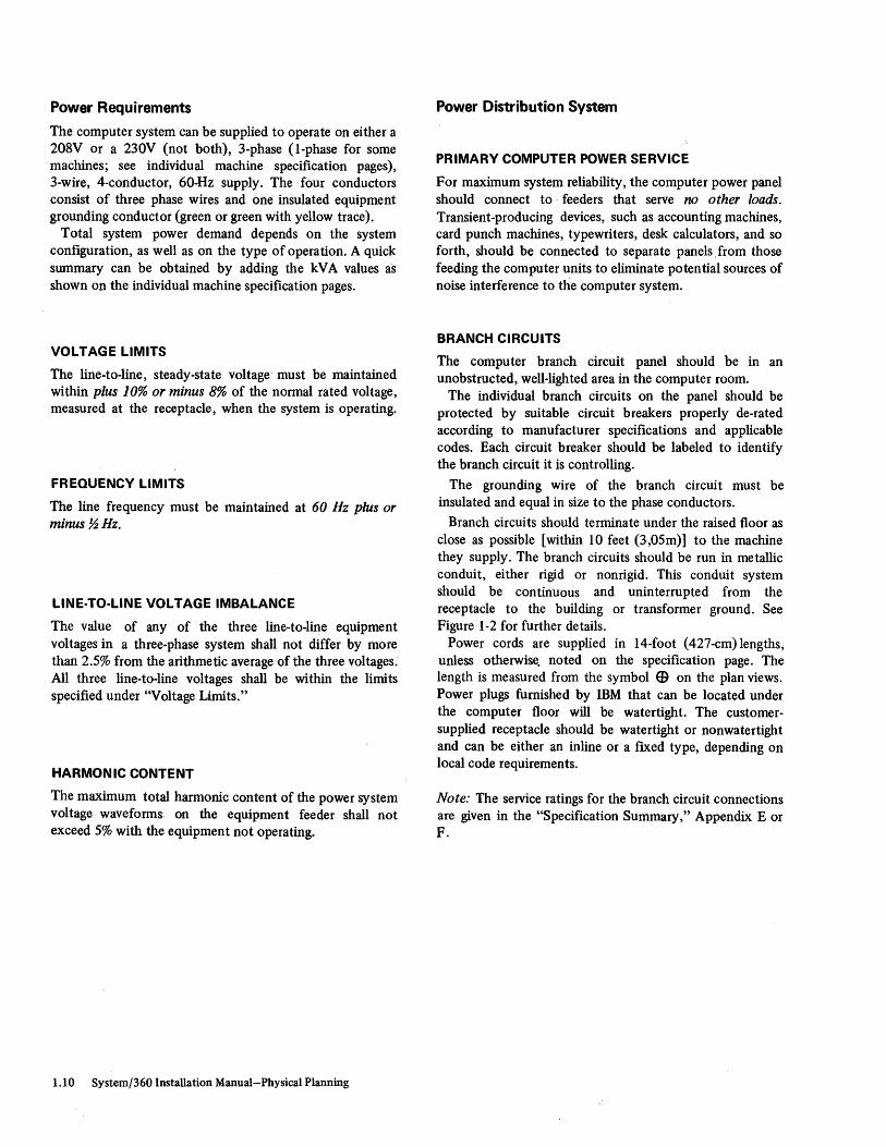
Power Requirements
The computer system can be supplied to operate on either a 208V or a 230V (not both), 3-phase (I-phase for some machines; see individual machine specification pages), 3-wire, 4-conductor, 60-Hz supply. The four conductors consist of three phase wires and one insulated equipment grounding conductor (green or green with yellow trace).
Total system power demand depends on the system configuration, as well as on the type of operation. A qUick summary can be obtained by adding the kV A values a's shown on the individual machine specification pages.
VOLTAGE LIMITS
The line-to-line, steady-state voltage' must be maintained within plus 10% or minus 8% of the normal rated voltage, measured at the receptacle, when the system is operating.
FR EQUENCY LIMITS
The line frequency must be maintained at 60 Hz plus or minus ~Hz.
LlNE-TO-LiNE VOLTAGE IMBALANCE
The value of any of the three line-to-line equipment voltages in a three-phase system shall not differ by more than 2.5% from the arithmetic average of the three voltages. All three line-to-line voltages shall be within the limits specified under "Voltage Limits."
HARMON IC CONTENT
The maximum total harmonic content of the power system voltage waveforms. on the equipment feeder shall not exceed 5% with the equipment not operating.
1.10 System/360 Installation Manual-Physical Planning
Power Distribution System
PRIMARY COMPUTER POWER SERVICE
For maximum system reliability, the computer power panel should connect to' feeders that serve no other loads. Transient-producing devices, such as accounting machines, card punch machines, typewriters, desk calculators, and so forth, should be connected to separate panels. from those feeding the computer units to eliminate potential sources of noise interference to tI1.e computer system.
BRANCH CIRCUITS
The computer branch circuit panel should be in an unobstructed, well-lighted area in the computer room.
The individual branch circuits on the panel should be protected by suitable circuit breakers properly de-rated according to manufacturer specifications and applicable codes. Each circuit breaker should be labeled to identify the branch circuit it is controlling.
The grounding wire of the branch circuit must be insulated and equal in size to the phase conductors.
Branch circuits should terminate under the raised floor as close as possible [within 10 feet (3,05m)] to the machine they supply. The branch circuits should be run in metallic conduit, either rigid or nonrigid. This conduit system should be continuous and uninterrupted from the receptacle to the building or transformer ground. See Figure 1-2 for further details.
Power cords are supplied in 14-foot (427-cm) lengths, unless otherwise. noted on the specification page. The length is measured from the symbol E9 on the plan views. Power plugs furnished by IBM that can be located under the computer floor will be watertight. The customersupplied receptacle should be watertight or nonwatertight and can be either an inline or a fIXed type, depending on local code requirements.
Note: The service ratings for the branch circuit connections are given in the "Specification Summary," Appendix E or F.

GROUNDING
All IBM units are provided with an equipment ground wire (green or green with yellow trace). At the branch circuit pa)1el, the green wire ground from all units must be tied into one main grounding conductor. This equipment grounding wire must be carried back to service ground or suitable building ground. This is a noncurrent-carrying ground, not a neutral. Conduit must not be used as the only grounding means.
Wherever possible, the system's power panel shall be mounted in contact with bare building steel or connected to it by a short length of cable. Where this is not possible, a metal area (power panel plus conduit plus plate) of at least 10 square feet (0,93m2) in contact with masonry shall be connected to the green-wire common. The connection shall not be more than 5 feet {152 cm} long and shall consist of #12 AWG [0.0051 square inches (3,3mm2}) or larger wire.
PHASE ROTATION
The three-phase power receptacles for use with the system must be wired for correct phase rotation. Looking at the face of the receptacle, and running counterclockwise from the ground pin, the sequencing will be phase 1, phase 2, and phase 3. See Figure 1-2.
EMERGENCY POWER-OFF CONTROLS
As a safety precaution, in addition to emergency power-off switches for individual components or other units of equipment, controls for the disconnecting provided as a part of the main service wiring supplying the electronic computer equipment shall be convenient to the operator. These controls should also be next to each exit door to readily disconnect power to all electronic equipment in the computer area and to the air conditioning system. Provision should be made for emergency lighting. See "Supporting Facilities" under "Safety and Fire Precautions" and notes on motor-gem ;ator specification pages.
LIGHTNING PROTECTION
It is recommended that the customer install lightning protection on his secondary power source when: 1. Primary power is supplied by an overhead power service. 2. The utility company installs lightning protectors on the
primary power source. 3. The area is subject to electrical storms or equivalent
type power surges. The determination as to whether lightning protection is
desirable, the selection of the service protector needed, and its proper installation are to be made by the customer.
CONVENIENCE OUTLETS
A suitable number of convenience outlets should be installed in the computer room and CE room for use by building maintenance personnel, porter service, customer engineers, etc. Convenience outlets should be on the lighting or other bUilding circuits, not on the computer power panel or feeder. See "CE Room and Test Area" for details of requirements in that area.
Under no circumstances are the system convenience outlets on IBM units to be used for any purpose other than normal servicing.
PRIMARY POWER PROBLEM AREAS
All reasonable efforts have been. made in the machine design to ensure satisfactory operation from the normal power supplied by most power companies. There are, however, many outside variables over which neither your power company nor IBM has any control. To guard against possible computer malfunctions caused by outside (radiated or conducted) transient electrical noise signals being superimposed on the power supplying your computer, power distribution design should comply with the computer system requirements specified in this manual.
Failures caused by your power supply are basically of two types:
1. Power Outages: This includes short duration dips in voltage as well as prolonged outages. If the frequency of such power failures is not acceptable for your operation, it may be necessary to install static, rotary, or a combination of both types of standby power systems. The IBM Installation Planning representative will discuss your application requirement with you.
2. Transient Electrical Noise Superimposed on Power Lines: This type of problem may be caused by a wide variety of industrial, medical, communications, or other equipment in the vicinity of the power company's distribution lines, or within or adjacent to your facilities. Electromechanical equipment such as adding machines, card punch machines, etc., on the same power source as the computer, may, under certain conditions, cause intermittent electrical disturbances.
If transient-producing devices have been eliminated from the feeder and the computer room power panel and power line disturbances are still present, it may be necessary for the customer to install isolation equipment (for example, transformers, motor generators, and so forth).
Preinstallation Planning 1.11

Notes:
Power Source
03
Noncurrent-carrying grounding conductor (See Note 2)
Remotely Operated
~ Transformer or suitable building grounding station
Plugs
208I230V~
~~
1. Remotely disengaged by an emergency device located near the console operator and next to the main exit door. 2. Ground wire (green or green with yellow trace).
Figure 1-2. Power Distribution System
1.12 System/360 Installation Manual-Physical Planning
From 30 Unit
From 10 Unit

Safety and Fire Precautions
Safety is a vital factor in planning for a large computer installation. This consideration is reflected· in the choice of . a computer location, building materials used, fire prevention equipment, air conditioning and electrical systems, and personnel training.
COMPUTER LOCATION
1. The computer area should be in a noncombustible or fire-resistive building or room.
2. The computer room should not be above, below, or adjacent to areas where inflammable or explosive materi~s or gases are stored, manufactured or processed. If the customer must locate near such an area, he should take precautions to safeguard the area.
FIRE PREVENTION CONSIDERATIONS
1. Walls enclosing a computer area should be of noncombustible materials. These walls should extend from floor to ceiling. If walls are made of combustible material, they should be protected as prescribed by code.
2. If a computer area has one or more outside walls adjacent to a building that is susceptible to fire: a. Installation of shatterproof windows in the computer
room would improve the safety of personnel and equipment from flying debris and water damage.
b. Sprinklers could be installed externally over the windows to protect them with a blanket of water if a fire occurs in the adjacent area.
c. Windows could be sealed with masonry. 3. Where a false (or hung) ceiling is to be added, it should
be constructed of noncombustible ot fire-resistant material. All ducts and insulating materials should be noncombustible and nondusting. If combustible materials are used in the space between the structural ceiling and the false ceiling, appropriate protection should be provided.
4. A raised floor, installed over the structural floor, should be constructed of noncombustible .or fire-retardant materials. If the structural floor is of combustible material, it should be protected from the ceiling below, preferably by water sprinklers. (Note: Before the computer is installed, the space between the raised and the structural floors should be cleared of debris. Also, this space should be periodically checked after installation, to keep it free of accumulated dust and possible debris.)
5. The roof or floor above the computer and tape storage areas should be a watertight slab. If practical, the walls of the room should be sealed to the slab in such a manner as to prevent water entering from above.
6. Sub floor space should be provided with positive drainage.
7. When machines are connected to a system but are located in a different room from the CPU (or system EPO), a switch that is capable of disconnecting power to the machine(s) shall be provided in the remote location. Check with your IBM Installation Planning representative to determine whether the remote IBM units can provide this switch function or whether a wall switch is required.
TYPE OF FIRE PREVENTION EQUIPMENT IN A COMPUTER AREA
1. An early-warning detection system should be installed to protect the computer and tape storage areas. This detection system should actuate an audible alarm.
2. Portable carbon dioxide fire extinguishers of suitable size [15 pounds (7 kg)] and number should be provided in the machine room. Carbon dioxide is a recommended nonwetting agent for electrical equipment (Class C Hazard). Extinguishers should be readily accessible to individuals in the area and extinguisher locations should be visibly marked overhead. Local codes govern the frequency of inspecting the cylinders.
3. Where portable carbon dioxide cylinders are used as the primary extinguishing agent, it is advisable to locate a standpipe or hose unit within effective range of the computer area as a secondary extinguishing agent or backup.
4. If the customer requires or prefers to have a roomflooding system installed, Halon 1301 (see NFPA No. 12A) can be considered on the basis of its excellent safety qualities.
5. In some cases, local codes and ordinances, or insurance regulations, require automatic water sprinklers. Preaction sprinkler systems should be considered if they conform to such codes and ordinances. High temperatures actuate heat-sensitive devices, which open a control valve. This valve, located outside the room, admits water into the sprinkler piping before the sprinkler heads operate. This type of system minimizes the possibility of accidental discharge of water because of failure or mechanical breakage of the automatic sprinkler heads.
DATA STORAGE
1. Any data stored in the computer room, whether in the form of magnetic tape, paper tape, cards, or paper forms, should be limited to the minimum needed for safe, efficient operation and should be enclosed in metal cabinets or fire-resistant containers.
2. For security purposes or for maintaining duplicates of master records, a separate storage room should be used. This room should be constructed of fire-resistant material and should contain the same type of fire prevention equipment as described in "Type of Fire Prevention Equipment in a Computer Area."
Preinstallation Planning 1.13

SUPPORTING FACILITIES
Air Conditioning Systems
1. In most installations, the computer area is controlled by a separate air conditioning system. In these cases, an emergency power-off switch should be placed in a convenient location, preferably near the console operator or next to the main exit door. Fusible-link dampers should be located at fire walls and at places as prescribed by local code. .
2. Where the regular building air conditioning system is used, with supplemental units in the computer area, the supplemental units would then be handled as stated in item 1. The regular building air conditioning system should have an alarm in the regular building maintenanc,Y area to alert the maintenance personnel of an emergency. Air ducts serving other areas but passing through the computer room should contain fusible-link dampers at each wall of the computer room.
3. The air filters used as part of the air conditioning system should contain noncombustible or self-extinguishing material.
Electrical Systems
1. The mainline breaker for the computer equipment should be remotely operated. The remote controls should be in a convenient location, preferably near the console operator and next to the main exit door. A light should be installed to indicate when power is on.
2. Some local codes require a special battery-operated lighting unit that will automatically illuminate an area if a power or lighting circuit failure occurs. These units are wired to and controlled by the lighting circuit. When not required by code, it is recommended that such lights be installed.
3. Watertight connectors should be used if they must be located where they may be exposed to excessive moisture. Proper drainage will guard against flooding or trapping water under the raised floor in the computer room. This is important in new buildings where the regular floor is recessed and the raised surface is on the level of the adjacent areas.
4. Where continuity of operation is essential, a'standby power source should be installed.
1.14 System/360 Installation Manual-Physical Planning
PREPLANNING TO CONTINUE OPERATION IN AN EMERGENCY
The continued operation of a customer's computer depends on information stored on cards, tapes, disks, drums~ and so forth. Also, equ~pment must be available to process the information. Arrangements should be made for emergency use of other equipment and transportation of personnel, data, and supplies to a temporary location. Duplicate or master records should be maintained from which the necessary information can be taken to resume operation. These records should be stored in a remote area.
GENERAL PRECAUTIONS AND PERSONNEL TRAINING
1. The computer room, air conditioning equipment room, and data, storage room should be monitored during nonoperating hours.
2. Steampipes and waterpipes above the false ceiling should be inspected to guard against possible damage because of accidental breakage, leakage, or condensation.
3. Emergency exit doors should be located in the computer area. The number of doors depends on the size and location of the area.
4. Personnel should be trained in emergency measures such as: a. Method and sequence of shutting off all electrical
power. b. Shutting off air conditioning system. c. Handling fire extinguishers in the approved manner. d. Operating a small-diameter fire hose. e. Evacuating records. f. Evacuating personnel. g. Calling fire company. h. First aid ...
ADDITIONAL REFERENCE MATERIAL
Consult NFPA Standard No. 75, "Protection of Electronic Computer/Data Processing Equipment."

Storage of Tape, Disk Pack, Disk Cartridge, and Data Cell
Storage facilities for frequent or infrequent usage of magnetic tape should be maintained within the following limits:
IBM Heavy-Duty Magnetic Tape Relative Humidity: 20% to 80% Temperature: 40° to 90°F (4° to 32°C)
Mylar* Tape-Long-Term Storage Relative Humidity: 20% to 80% Temperature: 50° to 90°F (10° to 32°C)
Tape exposed to atmospheric conditions outside the preceding limits will require reconditioning before it is used. This is accomplished by permitting the tape to remain in the correct operating environment for a length of time equal to the storage time (up to maximum reconditioning period of 24 hours).
The tape should be stored in a dustproof container in a vertical position and should never come in contact with magnetic material at any time_ Magnetic fields of greater than 50-oersted intensity can cause loss of information or introduction of noise~
When shipping magnetic tape, each reel should be sealed in a plastic bag and packed individually in stiff cardboard shipping boxes. These may be obtained from IBM.
* Trademark of E.I. du Pont de Nemours & Co. (Inc.)
The disk pack, disk cartridge, and data cell are precision instruments. Storage facilities should be maintained within the following limits:
Disk Pack and Disk Cartridge Short-Term Storage:
Temperature: 60° to 90°F (16° to 32°C) Relative Humidity: 10% to 80%
Long-Term Storage: Temperature: 40° to 150°F (4° to 66°C)
Data Cell Storage:
Temperature: 50° to 110°F (10° to 43°C) Relative Humidity: 8% to 80% Max Wet Bulb: 80°F (27°C)
Disk packs, disk cartridges, and data cells must be conditioned to the machine operating environment before use. This is accomplished by permitting the device to remain in the correct operating environment for a length of time equal to the time out of the operating environment (up to a maximum conditioning period of 2 hours).
These devices are equipped with dustproof covers which should be left in place, except when installed in the file. Storage should be in fire-resistant cabinets away from magnetic fields. Magnetic fields of greater th~m 50 oersteds\ can cause loss of information or introduction of noise.
Additional information concerning handling, operation, device dimensions, flammability characteristics, shipping requirements, and housekeeping is in IBM Disk Pack Handling and Operating Procedures, GA26-5756, and IBM Data Cell Handling Guide, GA26-3633.
Preinstallation Planning 1.15

Priority
INPUT/OUTPUT PRIORITY SEQUENCE
Channel capabilities are affected by the sequence in which I/O devices are attached to the channel. This sequence is called priority. This is most pronounced on the byte multiplexer channel. For assigning priorities, the devices are divided into three groups:
Class I: Devices subject to overrun. Class 2: Devices that require channel service in synchronization
with their mechanical operations. Class 3: Devices that do not require their channel service to be
in synchronization with their operations.
Device Wait (Critical) Time
After a multiplex-mode device requests channel service, it has a fixed length of time that it can wait for service. If the channel provides. service within this length of time, the device operates satisfactorily. If, however, the channel does not service the device within the device's wait time, either of two things happens: If the device is not subject to overrun, it continues waiting; if it is subject to overrun, it loses data and subsequently causes an I/O interruption condition. For example, when an IBM 1403 Printer on an overloaded byte multiplexer channel fails to receive data within its particular wait time, it merely waits until service is provided by the byte multiplexer channel. The delay does not cause an interruption condition, nor is a new start I/O instruction required for selecting the 1403. The only effect is a lessening in performance. If an IBM 1442 Card Read Punch read operation does not receive data service within its wait time, however, overrun occurs.
Wait (critical) time factors for multiplex-mode 4evices are listed in Appendix B.
In attaching devices to the byte multiplexer channel, the various classes are normally attached in numeric sequence (1, 2, and 3). Within each class, devices are usually attached in order of increasing critical time intervals. Differences in how individual I/O devices are programmed may require two I/O devices with either the same or nearly the same
~. critical times to be swapped in priority for proper operation. No information can be lost with devices of class 2 or 3. A device not required to operate at its rated performance may be attached with a lower priority than normally assigned.
1.16 System/360 Installation Manual-Physical Planning
Devices that operate in burst mode may be attached to byte multiplexer channel in any physical location; from a performance standpoint, these units should be assigned· lowest priority. On the selector or block multiplexer channel, devices are assigned priority according to data rate within class sequence.
In determining the attachment of I/O devices to selector or block multiplexer channels, the following guidelines generally apply. Class 1 devices with the highest data rates are normally attached to the lowest numbered channels (for example, channell). Because service to class 2 and 3 devices may be delayed without the· loss of information, they usually are attached to the highest numbered channels (for example, channels 3 and 4).
In determining the priority of control units which operate multiple devices with different priority rules (for example, a 2821 that attaches both class 2 and class 3 devices and the 2702 or tape control units that may attach devices with different data rates), the highest priority for any of the attached devices is normally used.
The class designation, critical time, and data rates for various units and features are in Appendix B. For additional information, see the appropriate system or channel characteristics publication.
Control units are addressed by the channel via a cable that contains "select in" and "select out" lines. A particular control unit can be connected to either line. Control units may be in any physical sequence on these lines that will permit connection in accordance with the prescribed priority sequence. Several physical sequences of units are usually possible that will provide the same priority sequence.
Cables must be ordered by starting at the unit most remote from the CPU. Cables are then specified from unit to unit back to the channel or CPU. It is necessary that the proper sequence be observed to ensure receiving the proper length cables. The machine type numbers used in the "From" and "To" columns of the cable order form determine the amount of cable required to connect to t4e proper location inside the units at each end of the cable. When ordering a cable to attach from one location to another within the same unit (for example, SF #1850 on one channel to another channel within the same unit), specify an "X" length of "0" feet, unless otherwise directed.

Cables
IBM supplies the necessary cables for the initial installation as specified in this manual. The cables are custom-made to the lengths required for each installation. Cables are measured in accordance with the approved layout. The group number and channel where required, along with the required cable length, must be submitted for each cable in the computer system. The required cable length is defined as the center-to-center distance between machine cable entry holes measured along the intended route of the cable as projected on the floor or other mounting surface. When machines are mounted on a raised floor, twice the height of the raised floor should be included in the required cable length. IBM makes allowance for the portion of each cable that is from the floor or mounting surface into the machine. For best electrical design and computer performance, all cable lengths should be kept as short as possible. External interconnecting cables should be installed under the raised floor. Where a raised floor is not used, these cables should be protected from mechanical damage, scuffing, and in a manner that will not present a safety hazard to operating personnel.
Orders for cables that exceed the maximum lengths specified for the system must be approved by IBM and may result in extra charges. Consult your IBM representative.
When a unit requires external cables which must be purchased by' the customer and installed through walls and/or floors, the purchase of this cable and the arrangements for its installation should be made with sufficient lead time to permit the cable facilities to be available to the computer system at installation time. This pertains to units such as the IBM 2260,3270,3704, and 3705.
CABLES SUPPLIED
Cables Related to Initial Installations
One cable or one "cable group" within standard specifications in accordance with an approved layout, required to install machines being delivered from IBM, will be supplied by IBM at no additional charge unless customer-supplied or a chargeable basis is indicated (such as for IBM 2260 cables). Orders for cables not within the standard specifications must be accompanied by an approved RPQ. For detailed instructions on entering cable orders, consult your IBM representative. Changes in cable order specifications requested within
three months of the scheduled date of shipment (or subsequent to any non-IBM-caused deferment within three months of scheduled date of shipment) may be subject to charge.
Any cables (of the type provided at no charge for an initial installation) required for rearrangement of previously installed IBM machines necessary to accommodate the installation of machines being delivered from IBM, will be supplied by IBM at no charge on an exchange basis. An explanation of why the cables are required must accompany the cable order. All replaced cables must be returned to IBM.
Other Cable Requests
Cables requested for other reasons (for example, additional or replacement cables for rearrangement not caused by installation of machines being delivered from IBM, cables to connect IBM and non-IBM equipment, etc.) will be considered only on an RPQ basis.
Preinstallation Planning 1.17

Field Engineering Support Facilities
CE ROOM AND TEST AREA
The customer engineers' test area for a single installation should contain between 70 and 400 square feet (7 and 38m2) of space depending on the size of the system,\and be air conditioned to the same specifications as the machine room.
The IBM Field Engineering Branch Manager will provide, on a scaled layout, the Field Engineering equipment which will be installed in the CE room to assist the customer in locating receptacles, lights, and so forth.
The test area should contain at least one 208V (or 230V), 3-phase, 20A power receptacle (Hubbell or Pass and Seymour type 7250 or equivalent) for operation of the tape unit testing equipment. At least two 115V, single-phase, 15A receptacles (convenience outlets) and other receptacles adequate to repair any unit that can be serviced in the CE room should be provided. The 115V receptacles (convenience outlets) should not be supplied power from the computer power panel.
FURNITURE AND FIXTURES
The furniture and fixtures for the CE room will be determined by local Field Engineering management and will vary according to the size of the system or systems installed and the number of customer engineers required.
The following is a partial list of typical furniture and fixtures:
Length Width Height in. em in. em in. em
Desk 45 114 34 86 29 74 Workbench 72 183 30 76 35 89 Shelf Cabinet 36 91 18 46 72 183 Parts Cabinet 42 107 24 61 87 221 File Cabinet 18 46 28 71 60 152 Bookcase 33-1/4 84 15-1/4 39 . 42 107 Study Table 60 152 30 76 29 74 Book Cart 40 102 13 33 31 79 Card File 17 43 24 61 9 23 Microfiche Viewer 24 61 24 61 54 137 Tool and Test Equipment
Cart 22 56 22 56 35 89
Templates for the furniture listed are available from IBM. See Appendix D for order (form) number.
RETAIN/370 SERVICE
The IBM 2955 Field Engineering Data Adapter Unit (FE DAU) for RETAIN/370 is used on System/360 Model 195. The 2955 has the following specifications:
Dimensions: See plan view on the following page.
Weight: 600 lb (280 kg)
Heat Output: 3,000 BTU/hr (760 kcal/hr)
1.18 System/360 Installation Manual-Physical Planning
Airflow: 120 cfm (4 m3/min)
Power Requirements: 1.0 kV A, single phase, 60 Hz
Power Plug: R&S, FS3720. Customer supplies either R&S, FS3743 receptacle or R&S, FS3913 connector.
Cabling Schematic: See Section 4.
Note: The FE DAU takes one control unit position on a byte multiplexer channel. It is a class 1 device with a critical time of 14.1/N.
BASIC STORAGE MODULE (8SM) ANALYZER
Provision must be made for testing the spare BSM for IBM System/360 Models 85 and 195.
The spare BSM is within the' frame of a mobile service cart. The physical dimensions and other specifications for the spare BSM and cart are:
Dimensions: See plan view on the following page.
Weight: 500 lb (230 kg)
Heat Output: BTU/hr (kcal/hr)
To Air 3,100 (790)
Airflow: 325 cfm (10 m3/min)
To Water 2,500 (630)
F or servicing, this cart must be near the analyzer. For the Model 85 with IBM 2385 Processor Storage
Modell or 2, the 415-Hz power for testing the spare BSM is supplied from the PDU (frame 14) via the analyzer. IBM furnishes the connector and up to 100 feet of cable to the analyzer. The 60-Hz power is supplied from the customer's wall outlet or inline connector. Coolant is supplied from the CDU (2385 frame 01) via 100 feet of hose.
The Model 85 test area will contain a BSM analyzer with ' the following specifications:
Dimensions: See plan view on the following page. I
Weight: 1,040 lb (480 kg)
HeatOutput: 12,900 BTU/hr (3.300 kcal/hr)
Airflow: 1,240 cfm (36 m3/min)
Power Requirements: 4.5 kV A, 60 Hz 3.0 kVA, 415 Hz
For the Model 195, specifications for the BSM analyzer are identical, except that no customer-supplied power plug or receptacle is needed because botl1 415-Hz and 60-Hz power are supplied from the IBM 3085 Power Distribution Unit (PDU), frame 09. Coolant is supplied from the IBM 3086 Coolant Distribution Unit '(CDU), frame 02, via 125 feet of hose.

System/360 and System/370 Field Engineering Furniture and Test Equipment
PLAN VIEWS
[J S H
Inches 45 34 29 (em) (114) (86) (74)
Parts Cabinet
F S H Inche: 42 24 87 (em) (107) (61) (221)
Study Table
F S H Inches 60 30 29 (em) (152) (76) (74)
Microfiche Viewer
F S H Inches 24 24 54 (em) (61) (61) (137).
Tool and Test
Equipment Cart
F S H Inches 22 22 35 (em) (56) (56) (89)
Workbench
S H ~~es n 30 ~ (em) (183) (76) (89)
Parts Cabi net
S H Inches 42 24 87
File Cabinet
F S H Inches 36 18 72 (em) (91) (46) (183)
File Cabinet
F S H
File Cabinet
F S H Inches 36 18 72 (em) (91) (46) (183)
BOokcase
F S H Inches 33-1/415-1/4 42 (em) (84) (39) (107)
(em) (107) (61) (221) F S H
Inches 18 28 60 (em) (46) (71) (152)
Inches 18 28 60 (em) (46) (71) (152)
F S H Inches 18 28 60 (em) (46) (71) (152)
Book Cart
F S H Inches 40 13 31 (em) (102) (33) (79)
F S H F S H Inches 52 29 70 Inches 52 29 70 (em) (132) (74) (178) (em) (132) (74) (178)
-+'I=-~,,- ~~5:'~ll i //[ i -:L til 42 "
I I II ti ~ ~ 25-1/2"
I I I 1 I I 42"
~ L ~J I 30"-.-l Front - I
L-e----~--&--J S H
Inches 40 25-1/2 40 (em) (102) (65) (102)
Book Cart
~ S H File
F Inches 40 13 31 (em) (102) (33) (79)
F S H Inches 17 24 9 (em) (43) (61) (23)
~3:'-Ff42_7;'-~ -;'1 <f> ' I
: t I I I 2" I I I I I ~ ~ i I L_l-& ___ ~_~:~
F S H Inches 29-1/2 42-7/8 70 (em) (75) (109) (178)
Preinstallation Planning 1.19

Standard Symbols
Figure 1-3 shows the symbols adopted as standard for the IBM Systemj360. Frame numbers are shown circled on plan views and cabling schematics, for example, @1).
In Plan Views:
1><1
EB r -" I I "-I I \
I \
r---
f CE
In Cabling Schematics:
~ ~
~ ~
Figure 1-3. Standard Symbols
Cable Entry and Exit Area in Base of Unit
Power Cord Exit
Swinging Gate
Standard Equipment Outline (Shows unit with covers closed)
Optional Equipment Ovtline
Customer Engineer Indicator Panel
Indicates Cable Group from a Unit, and
Indi cates Cable Group 1£ a Unit
1.20 System/360 Installation Manual-Physical Planning
~-B-
+ o
o
T M
Hinged Covers
Service Area Boundary (Service clearances are measured from unit with covers closed)
Casters
Leveling Pads or Glides (3-1/2" [8,9 cm] Typical Diameter)
Legs
Nonraised Floor Cable Exit
Meter Location
Single
Bifold
Offset Bifold
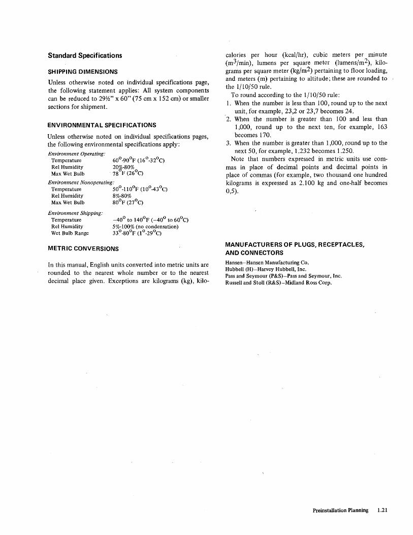
Standard Specifications
SHIPPING DIMENSIONS
Unless otherwise noted on individual specifications page, the following statement applies: All system components can be reduced to 29Y2" x 60" (75 cm x 152 cm) or smaller sections for shipment.
ENVIRONMENTAL SPECIFICATIONS
Unless otherwise noted on individual specifications pages, the following environmental specifications apply: Environment Operating:
Temperature ReI Humidity Max Wet Bulb
60°-90°F (16 0 -320 C) 20g;r80% 78 F (26°C)
Environment Nonoperating: Temperature 50°-110°F (10°-430 C) ReI Humidity 8%-80% Max Wet Bulb 80°F (27°C)
Environment Shipping: Temperature ReI Humidity Wet Bulb Range
-40° to 140°F (-40° to 60°C) 5%-100% (no condensation) 33° -80°F (1 ° -29°C)
METRIC CONVERSIONS
In this manual, English units converted into metric units are rounded to the nearest whole number or to the nearest decimal place given. Exceptions are kilograms (kg), kilo-
calories per hour (kcal/hr), cubic meters per minute (m3/min), lumens per square meter (lumens/m2), kilograms per square meter (kg/m2) pertaining to floor loading, and meters (m) pertaining to altitude; these are rounded to the 1/10/50 rule.
To round according to the 1/10/50 rule: 1. When the number is less than 100, round up to the next
unit, for example, 23,2 or 23,7 becomes 24. 2. When the number is greater than 100 and less than
1,000, round up to the next ten, for example, 163 becomes 170.
3. When the number is greater than 1,000, round up to the next SO, for example, 1.232 becomes 1.250.
Note that numbers expressed in metric units use commas in place of decimal points and decimal points in place of commas (for example, two thousand one hundred kilograms is expressed as 2.100 kg and one-half becomes 0,5).
MANUFACTURERS OF PLUGS, RECEPTACLES, AND CONNECTORS
Hansen-Hansen Manufacturing Co. Hubbell (H}-Harvey Hubbell, Inc. Pass and Seymour (P&S}-Pass and Seymour, Inc. Russell and Stoll (R&S)-Midland Ross Corp.
Preinstallation Planning 1.21
ABBREVIATIONS AND DEFINITIONS
A ambient AWG
blk mpxr bpi bps BSM BTU bus
C CCITT
CDU CE CER cfm ch cm conn CPU CRT C-T-C
DAA DAU dist
EIA EPO
F FE FEDAU fr ft
gpm
H hp Hz
in. I/O
kcal/hr kg kg/cm2
kg/m2
kVA
L lb lumens/m2
m max MCM m3/min
ampere environment American wire gauge
block multiplexer bits per inch bits per second basic storage module British thermal unit one or more conductors used for
transmitting signals or power
Celsius/ coupler Consultant Committee of International
Telephone & Telegraph (WT) coolant distribution unit customer engineer customer engineering room cubic feet per minute channel centimeter connector central processing unit cathode-ray tube connector-to-connector
Data Access Arrangement data adapter unit distribution
Electronic Industry Association sequence and control
Fahrenheit/front field engineering Field Engineering Data Adapter Unit frame feet
gallons per minute
height/H ub bell high pressure/horsepower hertz
inch input/output
kilocalories per hour kilogram kilograms per square centimeter kilograms per square meter kilovolt ampere
left pound lumens per square meter
meter maximum thousand circular mils cubic meter per minute
1.22 System/360 Installation Manual-Physical Planning
mfg MG min mm MP mpxr ms MTU
N
NEMA
NFPA No.
00 oersted
ohm
P&S PDU pH ppm proc psi psig pwr
R R&S rdr ReI RPQ Rt
S SCU sec service clearance
SF sIr stg
TNL
UK U.S.
V VFL
WT
manufacturing motor generator minimum/minute millimeter multiprocessing multiplexer millisecond magnetic tape unit
in sorting, fIle size, the number of records to be processed by the sort
National Electrical Manufacturers' Association
National Fire Protection Association number
outside diameter centimeter-gram-second electromagnetic
unit of magnetic intensity practical meter-kilogram-second unit of
electrical resistance equal to the resistance of a circuit in which a potential difference of 1 volt produces a current of 1 ampere
Pass and Seymour power distribution unit hydrogen-ion concentration parts per million processing pounds per square inch pounds per square inch gauge power
rear Russell & Stoll reader relative Request for Price Quotation right
side storage control unit second minimum space required to allow
working room for the machine operator and/or the customer engineer for servicing the unit
special feature selector storage
Technical Newsletter
United Kingdom United States
volt variable field length
World Trade

Section 2. System Specifications and Cabling Schematics

SYSTEM/360 MODEL 22, 2022 PROCESSING UNIT
PLAN VIEW
o -e- - e- --e- --() - --e-- ---E) - ~
I 24" r;;T~~:~ 3" F:,:' 2" 10" ~
I T ;' I (7 Places) I + ~ ~ I ~6"x8" I
I T / W ~;~)' "'1' \ t I "'iL£l; ~j\-----]-#t 1" f t 'roo' 1" 3' l,,,i + 20" (2 Places) l' i
I ;-----;-f-1 t Cj) I I I 20" cv I I I Forms I I
I I Carrier I +
tb4B
" 7-1/" '::" C:J --" t 40-1/2" 67-1/2" 30"-1
L ----0 - -e--- --e- ---8 - G-- -e----J
2022.1 Installation Manual-Physical Planning
SPECIFICATIONS
Dimensions: *
F S H
Inches ** ** 60 (cm) (**) (**) (152)
Service Clearances:
F R Rt L
Inches ** ** ** ** (cm) (**) (**) (**) (**)
Weight: 1,5001b (690 kg)
Heat Output: 6,900 BTU/hr (1.750 kcal/hr)
Airflow: 900 cfm (26 m3/min)
Power Requirements: kVA 2.4 Phases Plug Connector Receptacle Power Cord Style
Notes:
3 R&S, FS3730 R&S, FS3914 R&S, FS3744 D3
* Unless otherwise specified, the shipping dimensions on the 2022 are 32" x 68" x 64" (81 cm x 173 cm x 163 cm). Removal of the side covers reduces the width to 29" (74 cm). If further reduction in length is required, see sales representative for method of specifying on the order. This modifies the unit to 29" x 60" x 70" (74 cm x 152 cm x 178 cm).
** See plan view.
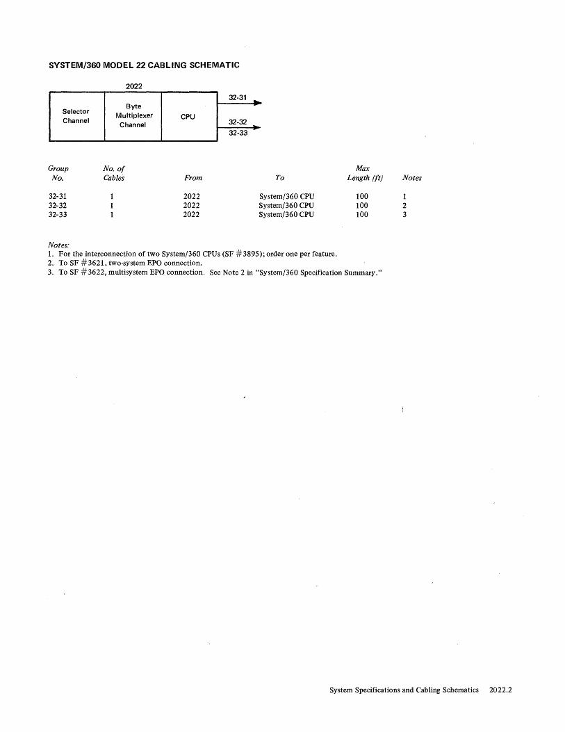
SYSTEM/3GO MODEL 22 CABLING SCHEMATIC
2022
32-31 ....
Selector Byte
Multiplexer CPU Channel Channel 32-32 ...
32-33 r
Group No. of Max No. Cables From To Length (ft) Notes
32-31 2022 System/360 CPU 100 1 32-32 2022 System/360 CPU 100 2 32-33 2022 System/360 CPU 100 3
Notes: 1. For the interconnection of two System/360 CPUs (SF #3895); order one per feature. 2. To SF #3621, two-system EPO connection. 3. To SF #3622, multisystem EPO connection. See Note 2 in "System/360 Specification Summary."
System Specifications and Cabling Schematics 2022.2
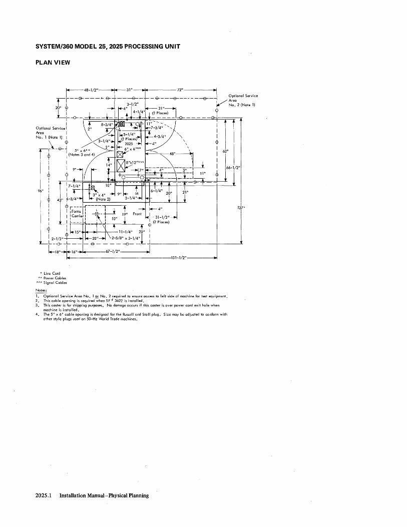
SYSTEM/360 MODEL 25,2025 PROCESSING UNIT
PLAN VIEW
72" ~I _ &---6---- - ----e----, OptIonal ServIce
V Area No.2 (Note 1)
9 I
62"
43"
t iF:r~; 1:--1\-,--1 + t" I I Carrier I L I 19
I I , I 10" I I I I L ___ :L__ _ + <D (2 Places)
rt I + + 'I 6 15" 11-1/4" 20" I
127"
I 2-1/2" 20" 2-5/8" x 3-1/4"ll L - -G- _L - - - -e- - - - - --0- - J--------__ -t-__ --L
lI8"-i16" J 67-1/2" ' ~I
* Line Cord ** Power Cables
*** Signal Cables
Notes:
151-1/2"----~
1. Optional Service Area No. 1 ~ No.2 required to ensure access to left side of machine for test equipment. 2. This cable opening is required when SF # 3622 is installed. 3. This caster is for shipping purposes. No damage occurs if this caster is over power cord exit hole when
machine is installed. 4. The 5" x 6" cable opening is designed for the Russell and Stoll plug. Size may be adjusted to conform with
other style plugs used on 50-Hz World Trade machines.
2025.1 Installation Manual-Physical Planning

SYSTEM/360 MODEL 25,2025 PROCESSING UNIT
SPECIFICATIONS
Dimensions: * F S H
Inches ** ** 60 (cm) (**) (**) (152)
Service Clearances:
F R Rt L
Inches ** ** ** ** (cm) (**) (**) (**) (**)
Weight: 2,0501b (930 kg)
Heat Output: 20,500 BTU/hr (5.200 kcal/hr)
Airflow: 800 cfm (23 m3/min)
Power Requirements: kVA Phases Plug Connector Receptacle Power Cord Style
Environment Operating:
7.4 3 R&S, SC7328 R&S, SC7428 R&S, SC7324 E3 or E5***
Temperature 60°-90°F ( 16°-32°C) ReI Humidity 80/0-80% Max Wet Bulb 78°F (26°C)
Notes: * Unless otherwise specified, the shipping dimen
sions on the 2025 are 31" x 66-1/2" x 64" (79 cm x 169 cm x 163 cm). Removal of the side covers reduces the width to 29" (74 cm). If further reduction in length is required, request special shipping group. This modifies the unit to 29" x 60" x 70" (74 cm x 152 cm x 178 cm).
** See plan view.
*** For machines with serial numbers 10001 through 10105 and 10133 through 10160, use power cord style E3. For machines with serial numbers 10106,10132,10161, and higher, use power cord style E5 .
System Specifications and Cabling Schematics 2025 .2

SYSTEM/360 MODEL 25 CABLING SCHEMATIC (WORLD TRADE)
3512 or
3513
...
3501
3507
..... ,.
634
2311
Power Entry
(See specifications page for location)
Sequence and Control (EPO) (Note 6)
Control Unit
2025
(Note 7)
,..----------.,. 3521 3524 J----------~
2560-A 1 3522 (Note 11)
3505 3504 2540
3502 or 3520 1403
(Note 14)
3508 \
2311 #1 630 ...
I ,.
634
630 .... ,. 2311
634
630 2311
630
Communications Attachments
Signal Entry (See specifications page for location)
Data Set-EIA Interface (Note 8) ________________ 35_16_an_d_/_o_r_3_5_17--J
443 446 and/or 447 ~--~-2711 (Note 13) --------------------------------------------~
3518 Telegraph (Note 9) ____________________________ ..J
3526 and/or 3527 DataSet-Synchronous and Dual Interface (Note 10) -----------------~
3510 or 3511 Direct Control (Notes 2 and 3)----------------------~-----J
~ Multiple System EPO (Notes 4 and 5)
2025.3 Installation Manual-Physical Planning
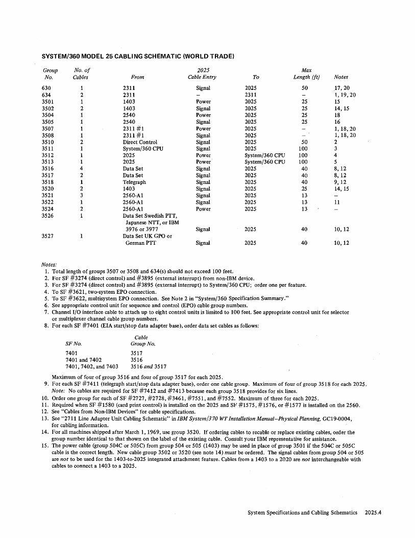
SYSTEM/3GO MODEL 25 CABLING SCHEMATIC (WORLD TRADE)
Group No. of 2025 Max No. Cables From Cable Entry To Length (ft) Notes
630 1 2311 Signal 2025 50 ,17,20 634 2 2311 2311 1,19,20 3501 1 1403 Power 2025 25 15 3502 2 1403 Signal 2025 25 14,15 3504 1 2540 Power 2025 25 18 3505 1 2540 Signal 2025 25 16 3507 1 2311 #1 Power 2025 1, 18,20 3508 1 2311 #1 Signal 2025 1, 18,20 3510 2 Direct Control Signal 2025 50 2 3511 1 System/360 CPU Signal 2025 100 3 3512 1 2025 Power System/360 CPU 100 4 3513 1 2025 Power System/360 CPU 100 5 3516 4 Data Set Signal 2025 40 8,12 3517 2 Data Set Signal 2025 40 8, 12 3518 1 Telegraph Signal 2025 40 9,12 3520 2 1403 Signal 2025 25 14,15 3521 3 2560-A1 Signal 2025 13 3522 1 2560-A1 Signal 2025 13 11 3524 2 2560-A1 Power 2025 13 3526 1 Data Set Swedish PTT,
Japanese NTT, or IBM 3976 or 3977 Signal 2025 40 10,12
3527 Data Set UK GPO or GermanPTT Signal 2025 40 10,12
Notes: 1. Total length of groups 3507 or 3508 and 634(s) should not exceed 100 feet. 2. For SF #3274 (direct control) and #3895 (external interrupt) from non-IBM device. 3. For SF #3274 (direct control) and #3895 (external interrupt) to System/360 CPU; order one per feature. 4. To SF #3621, two-system EPa connection. 5. To SF #3622, multisystem EPa connection. See Note 2 in "System/360 Specification Summary." 6. See appropriate control unit for sequence and control (EPa) cable group numbers. 7. Channel I/O interface cable to attach up to eight control units is limited to 100 feet. See appropriate control unit for selector
or multiplexer channel cable group numbers. 8. For each SF #7401 (EIA start/stop data adapter base), order data set cables as follows:
SF No.
7401 7401 and 7402 7401,7402, and 7403
Cable Group No.
3517 3516 3516 and 3517
Maximum of four of group 3516 and four of group 3517 for each 2025. 9. For each SF #7411 (telegraph start/stop data adapter base), order one cable group. Maximum of four of group 3518 for each 2025.
Note: No cables are required for SF #7412 and #7413 because each group 3518 provides for six lines. 10. Order one group for each of SF #2727, #2728, #3461, #7551, and #7552. Maximum of three for each 2025. 11. Required when SF #1580 (card print control) is installed on the 2025 and SF #1575, #1576, or #1577 is installed on the 2560. 12. See "Cables from Non-IBM Devices" for cable specifications. 13. See "2711 Line Adapter Unit Cabling Schematic" in IBM System/370 WT Installation Manual-Physical Planning, GC19-0004,
for cabling information. 14. For all machines shipped after March I, 1969, use group 3520. If ordering cables to recable or replace existing cables, order the
group number identical to that shown on the label of the existing cable. Consult your IBM representative for assistance. 15. The power cable (group 504C or 505C) from group 504 or 505 (1403) may be used in place of group 3501 if the 504C or 505C
cable is the correct length. New cable group 3502 or 3520 (see note 14) must be ordered. The signal cables from group 504 or 505 are not to be used for the 1403-to-2025 integrated attachment feature. Cables from a 1403 to a 2020 are not interchangeable with cables to connect a 1403 to a 2025.
System Specifications and Cabling Schematics 2025.4
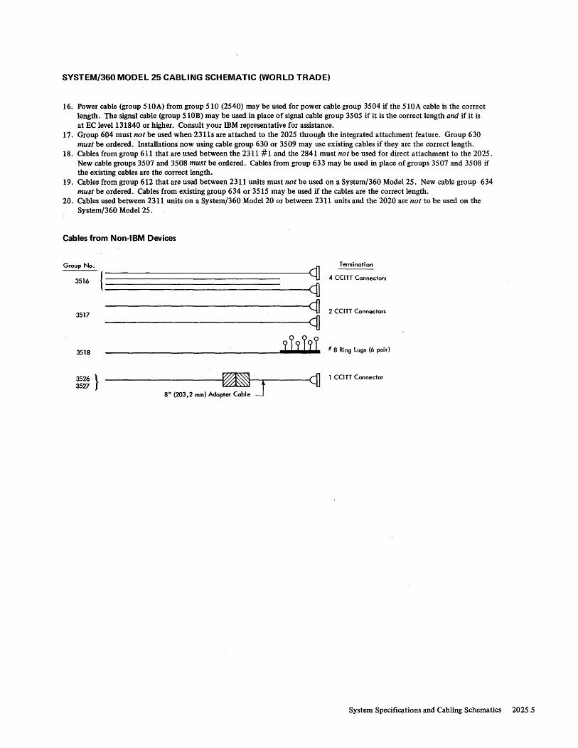
SYSTEM/360 MODEL 25 CABLING SCHEMATIC (WORLD TRADE)
16. Power cable (group 510A) from group 510 (2540) may be used for power cable group 3504 if the 510A cable is the correct length. The signal cable (group 510B) may be used in place of signal cable group 3505 if it is the correct length and if it is at EC level 131840 or higher. Consult your IBM representative for assistance.
17. Group 604 must not be used when 2311s are attached to the 2025 through the integrated attachment feature. Group 630 must be ordered. Installations now using cable group 630 or 3509 may use existing cables if they are the correct length.
18. Cables from group 611 that are used between the 2311 #1 and the 2841 must not be used for direct attachment to the 2025. New cable groups 3507 and 3508 must be ordered. Cables from group 633 may be used in place of groups 3507 and 3508 if the existing cables are the correct length.
19. Cables from group 612 that are used between 2311 units must not be used on a System/360 Model 25. New cable group 634 must be ordered. Cables from existing group 634 or 3515 may be used if the cables are the correct length.
20. Cables used between 2311 units on a System/360 Model 20 or between 2311 units and the 2020 are not to be used on the System/360 Model 25.
Cables from Non-18M Devices
Group No.
3516
3517
3518
3526 } 3527
-----------cfl Termination
4 CCITT Connectors
-------ct) ------~q]
2 CCITT Connectors
----------1 919191 # 8 Ring lugs (6 pair)
-------------~--r------cfl 1 CCITT Connector
8" (203,2 mm) Adapter Cable J
System Specificjltions and Cabling Schematics 2025.5

SYSTEM/3GO MODEL 25 CABLING SCHEMATIC (U.S.)
3512 or
3513
-...
Power Entry
(See specifications page for location)
Sequence and Control (EPO) (Note 6)
Control Unit
2025
(Note 7)
----------------- 3521 3523 1----------'
2560-A 1 3522 (Note-12)
3503 3505 2540
Signal Entry (See specifications page for location)
3501 3502 or 3520 1403
(Note 15)
3506 3508
630 ~--4-~ ______________ j_~--------------~
I 632 '"
2311 #1
630 ... 2311
632
2311 630
632
2311 630
Communications Attachments
Data Set--EIA Interface (Note 8) _____ -:--_________ ..:.35..:......:...16.:...:.a..:.nd.:;,:/..:.o_r..:.3...:..5...:..17--1
443 2711 (N 14) 446 and/or 447 ~---- ate -----------------------------------~----~
3518 Telegraph (Note 9) __________________________ -=---=-...J
Data Set-Autocall (Note 10) _________________________ -=-35;:,.1,;..:9;..,J
3526 Data Set-Synchronous and Dual I nterface (Note 11) ________________ :...:...::..=......J
DirectControl(Nohs2a~~------------------------------~35;:,.1,;..:0~o::..r-3::..5,;..:1..:.1...J
~ Multiple System EPO (Notes 4 and 5)
2025.6 Installation Manual-Physical Planning

SYSTEM/360 MODEL 25 CABLING SCHEMATIC (U.S.)
Group Woo of 2025 Max No. Cables From Cable Entry To Length (ft) Notes
63.0 1 2311 Signal 2025 50 18,21 632 2 2311 2311 1,2.0,21
35.01 1 14.03 Power 2.025 25 16 35.02 2 1403 Signal 2025 25 15, 16 3503 1 254.0 Power 2025 25 17 35.05 1 254.0 Signal 2.025 25 17 3506 1 2311 #1 Power 2025 1,19,21 35.08 1 2311 #1 Signal 2.025 1,19,21 351.0 2 Direct Control Signal 2.025 5.0 2 3511 1 System/36.o CPU Signal 2.025 10.0 3 3512 1 2.025 Power System/36.o CPU 10.0 4 3513 1 2.025 Power System/36.o CPU 1.0.0 5 3516 4 Data Set Signal 2.025 4.0 8,13' 3517 2 Data Set Signal 2.025 4.0 8,13 3518 1 Telegraph Signal 2.025 4.0 9,13 3519 4 Data Set (Auto call) Signal 2.025 4.0 1.0,13 352.0 2 14.03 Signal 2.025 25 15, 16 3521 3 2560-A1 Signal 2.025 13 3522 1 2560-A1 Signal 2.025 13 12 3523 2 256.o-A1 Power 2.025 13 3526 1 Data Set (Synchronous) Signal 2.025 4.0 11,13
Notes: 1. Total length of groups 3506 or 3508 and 632(s) should not exceed 100 feet. 2. For SF #3274 (direct control) and #3895 (external interrupt) from non-IBM device. 3. For SF # 3274 (direct control) and # 3895 (external interrupt) to System/360 CPU; order one per feature. 4. To SF #3621, two-system EPO connection. 5. To SF #3622, multisystem EPO connection. See Note 2 in "System/36.o Specification Summary." 6. See appropriate control unit for sequence and control (EPO) cable group numbers. 7. Channel I/O interface cable to attach up to eight control units is limited to 100 feet. See appropriate control unit for selector or
multiplexer channel cable group numbers. 8. For each SF #7401 (EIA start/stop data adapter base), order data set cables as follows:
, SF No.
7401 7401 and 74.02 7401, 74.02, and 74.03
Cable Group No.
3517 3516 3516and 3517
Maximum of four of group 3516 and four of group 3517 for each 2.025. 9. For each SF # 7411 (telegraph start/stop data adapter base), order one cable group. Maximum of four of group 3518 for each 2.025.
Note: No cables are required for SF #7412 and #7413 because each group 3518 provides for six lines. 1.0. For SF # 13.00 (autocall adapter base), order data set cables as follows:
SF No. 130.0 1300 and 1301 13.0.0, 13.01, and'. 13.02
Cable Group No. One 3519 One 3519 Two 3519s
11. Order one group for each of SF #2727, #2728, #3461, #7551, and #7552. Maximum of three for each 2.025. 12. Required when SF # 158.0 (card print control) is installed on the 2.025 and SF # 1575, # 1576, or # 1577 is installed on the 256.0. 13. See "Cables from Non-IBM Devices" for cable specifications. 14. See "2711 Line Adapter Unit Cabling Schematic" in IBM System/370 Installation Manual-Physical Planning,
GC22-70.o4, for cabling information. 15. For all machines shipped after March 1, 1969, use group 352.0. If ordering cables to recabie or replace existing cables, order the group
number identical to that shown on the lab~l of the existing cable. Consult your IBM representative for assistance. 16. The power cable (group 5.o4C or 5.o5C) from group 5.04 or 5.05 (14.03) may be used in place of group 35.01 if the 5.o4C or 5.o5C cable is
the correct length. New cable group 35.02 or 352.0 (see note 15) must be ordered. The signal cables from group 5.04 or 5.05 are not to be used for the 14.o3-to-2.o25 integrated attachment feature. Cables from a 1403 to a 2.02.0 are not interchangeaBle with cables to connect a 14.03 to a 2.025.
System Specifications and Cabling Schematics 2.025.7

SYSTEM/3GO MODEL 25 CABLING SCHEMATIC (U.S.)
17. Power cable (group 503A) from group 503 (2540) may be used for power cable group 3503 if the 503A cable is the correct length. The signal cable (group 503B) may be used in place of signal cable group 3505 if it is the correct length and if it is at EC level 131840 or higher. Consult your IBM representative for assistance.
18. Group 604 must not be used when 2311s are attached to the 2025 through the integrated attachment feature. Group 630 must be ordered. Installations now using cable group 630 or 3509 may use existing cables if they are the correct length.
19. Cables from group 605 that are used between the 2311 # 1 and the 2841 must not be used for direct attachment to the 2025. New cable groups 3506 and 3508 must be ordered. Cables from group 631 may be used in place of groups 3506 and 3508 if the existing cables are the correct length.
20. Cables from group 606 that are used between 2311 units must not be used on a System/360 Model 25. New cable group 632 must be ordered. Cables from existing group 632 or 3514 may be used if the cables are the correct length.
21. Cables used between 2311 units on a System/360 Model 20 or between 2311 units and the 2020 are not to be used on the System/360 Model 25.
Cables from Non-IBM Devices
Group No .. Termination
3516 } -----------------Ict] 3519 ---------------------------------------------------------------~ct]
4 EIA .RS-232A Connectors
{ ---------------------------------~~ 3517 <fl 2 EIA RS-232A Connectors
3518 #8 Ring Lug~ (6 pair)
3526 ________________ -.,_ ..... :---------<1] 1 EIA RS-232A Connector
8" (203,2 mm) Adapter Cable~
System Specifications and Cabling Schematics 2025.8
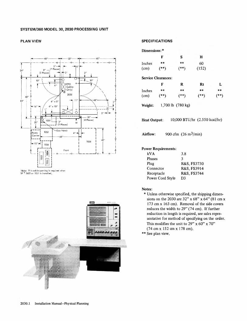
SYSTEM/360 MODEL 30, 2030 PROCESSING UNIT
PLAN VIEW
I" 48" 32"1G.~60" "I li----O---- ~ ,~ -- -<>-l-:" ~- -- -<> -- --O-i 24" I 8" (7 Place,) d,
I (3 Place,) 2" I ~ I I I I I
b + I I I I I
84" 68" r 48"~ 1
I ~ 3''1 i.- 16"l ------ -- ------,~ I I -- -- -- --- -- ---tl f I
I ~~±~~~~ 2 ,,~1- ct> g 30"-----1 I (4 Place,) I
I I
M
..----" (See Na.e) I ~--- - -, 1 r jFarm.' i 1052 ! 4 " ~ I I ,Corner If I 68 " I" , I ? !----.... I I I lI5 ,, ~.t :~:S: 1.J I 1058: 4
l2" I
I __ L ___ ~ I I I
J : 00 ' Fran. I I d, L_ I ~ ~ : - e- -----o-- L ___ --1 e _ - e- - J
I M - I
! ~ ~~ ! I o . I - I L ______ .J
No te: This coble ope ning is required when SF I 3622 or 105 1 is insta ll ed.
2030.1 Installation Manual-Physical Planning
SPECI FICATIONS
Dimensions: * F S H
Inches ** ** 60 (cm) (**) (**) (152)
Service Clearances:
F R Rt L
Inches ** ** ** ** (cm) (**) (**) (**) (**)
Weight: 1,7001b (780 kg)
Heat Output : 10,000 BTU/hr (2.550 kcal/hr)
Airflow: 900 cfm (26 m3/min)
Power Requirements: kVA Phases Plug Connector Receptacle Power Cord Style
Notes:
3.8 3 R&S, FS3730 R&S, FS3914 R&S, FS3744 D3
* Unless otherwise specified, the shipping dimensions on the 2030 are 32" x 68" x 64" (81 cm x 173 cm x 163 cm). Removal of the side covers reduces the width to 29" (74 cm). If further reduction in length is required, see sales representative for method of specifying on the order. This modifies the unit to 29" x 60" x 70" (74 cm x 152 em x 178 cm).
** See plan view.

SYSTEM/3GO MODEL 30 CABLING SCHEMATIC
2030
I
Channel-to-Selector Selector Channel Multiplexer Channel Channel
Adapter Channel (SF #1850)
1 2
JI' t ~ I ____ J ____ J
30-03 30-06 30-07 30-08
If
Other Control Unit, Channel, or Adapter
Group No.
30-02 30-03 30-04 30-05 30-06 30-07 30-08 30-09 30-10
Notes:
30-05
No. of Cables
2 2 1 2 2 2 2 1 1
From
Direct Control 2030 System/360 CPU 2030 2030 2030 2030 2030 2030
CPU ~ .....
To
2030 Control Unit> 2030 2030
30-02
30-04
30-09 ... 30-10
--~
Selector Channel Multiplexer Channel Channel-to-Channel Adapter System/360 CPU System/360 CPU
1. From channel-to-channel adapter (SF #1850); maximum cable length of 100 feet available to attach up to seven control units.
2. For the interconnection of two System/360 CPUs (SF #3274 and #3895); order one per feature. 3. Channel-to-channel adapter (SF #1850) to the channel within the same unit (maximum of one required). 4. For SF #3274 and #3895 from non-IBM device. 5. To SF #3621, two-system EPQ connection. 6. To SF #3622, multisystem EPQ connection. See Note 2 in "System/360 Specification Summary."
Max Length (ft)
50
100 (Fixed)
100 100
Notes
4 1 2 3 1 1 1 5 6
System Specifications and Cabling Schematics 2030.2

SYSTEM/360 MODEL 40, 2040 PROCESSING UNIT
PLAN VIEW
(Models G F and H O nl y) fa- - - - - -a- - r=-=-=6N/40' &- - - ---; I-(}-- -11 I i 3-1/2 " rr 3- 1/4" 36" I 1 3 1" (4 Places) (4 Places) . I
1 (2 Places) 1-1 1/16" I 1 + (4 Places) t f I 1 (Mode ls D to G) 1 ,<>---T ---<>--1 26~
I IS" 10" x 10" * 1 t -.:LL----'16" 1 1 $0 ~-----; I
I 13- 5/ 16 " / 1 1 (4 Places)' I
1 6- 7/ f/ ~ r --(4 :~~~ces) 60 " i 1 29" 30,, -.1 I. 60" 1 b 0 3-1/2" f 1 'f I 1 h 1 I M I 20" 1
I : ~ b f L;_-_-:.--:.-:--:, -----,--f- f 1
1 ,-----, I Fron t I r'" I I I I Ii i
I 1 :: : i Fo,ms I 20" I I I I I I I ~,"'!.'J ~ 1 i L---~ ____ J 4S" t~:,--r: -t i I I 67- 1 ;1"~ i L-e- _____ -<>_=_--<>- ____ -<> ____ ---.J
Weight Heat Output A irflo w From e
Ib 1 kg BTU/ h, 1 kcol/h, cfm 1 m3/m in
0 1 1,700 I 7S0 7 , 000 I I.SOO 300 I 9 02 6 10 280 3,500 890
2040.1 Installation Manual- Physical Planning
SPECI FICATIONS
Dimensions:
F S H
Inches * * 60** (cm) (*) (*) (152**)
Service Clearances:
F
Inches * (cm) (*)
Weight: Ib (kg)
Heat Output: BTU/hr (kcal/hr)
Airflow: cfm (m3/min)
R
* (*)
DtoG 1,700 (780)
Models
7,000 (L800)
300 (9)
Power Requirements: kVA 2.5
Rt
* (*)
GF and H 2,310 (1 .050)
10,500 (2.650)
300 (9)
3.7 Phases 3 3 Plug R&S, FS3760 Connector R&S, FS3934 Receptacle R&S, FS3754 Power Cord Style Bl
Environment Operating: Temperature 60°-90°F (l6° -32°C) ReI Humidity 100/0-80% Max Wet Bulb 78°F (26°C)
Environment Nonoperating: Temperature 50°_110°F (100 43°C) ReI Humidity 100/0-80% Max Wet Bulb 80°F (27°C)
Notes: * See plan view.
** Shipping height is 70" (178 cm) for Models GF and H.
L
* (*)

SYSTEM/360 MODEL 40 CABLING SCHEMATIC
Channel-to- Selector Channel Channel Adapter 1 {SF #1850)
40-03 40-04 40-05 40-06
" Other Control Unit, Channel, or Adapter
Group No. of No. Cables
40-01 2 40-02 1 40-03 2 40-04 2 40-05 2 40-06 2 40-07 1 40-08 1
Notes:
2040
Selector Multiplexer Channel Channel
2 CPU
From
Direct Control System/360 CPU 2040 2040 2040 2040 2040 2040
40-07"" 40-08 ,.
__ 40-01
~. 40-02
To
2040 2040 Control Unit Selector Channel Multiplexer Channel Channel-to~hannel Adapter System/360 CPU System/360 CPU
1. From channel-to-channel adapter (SF #1850); maximum cable length of 200 feet (unless modified by general control-to-channel cabling schematic) available to attach up to seven control units ..
2. For the interconnection of two System/360 CPUs (SF #3274); order one per feature. 3. For SF #3274 from non-IBM device. 4. To SF #3621, two-system EPO connection. 5. To SF #3622, multisystem EPO connection. See Note 2 in "System/360 Specification Summary."
Max Length (ft)
50 100
100 100
Notes
3 2 1 1 1 1 5 4
System Specifications and Cabling Schematics 2040.2
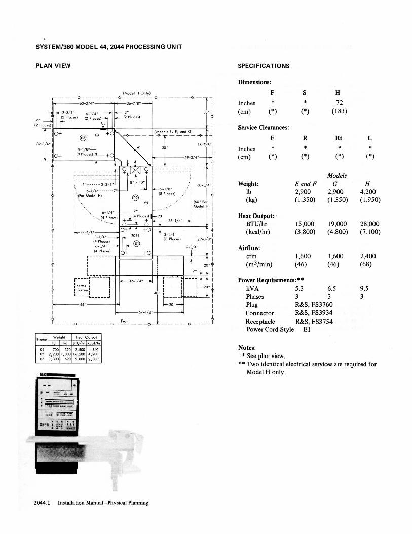
SYSTEM!360 MODEL 44, 2044 PROCESSING UNIT
PLAN VIEW
(Model H On ly)
~ - - -:~~---~-;~-~----~-ll 2- 3/ 4" 6-1/~4' 2" 30" J,
7" (2 Ploce,) (2 Piece,) (2 Piece,) ']'
(2 Piece,) I CE I
r 0 + (Mode l, E, F, end G) I @) ffi -4T - - - --e- -j
32- 1/4" : 36- 7/ 8 ,,1
lOt 30" I ~-t---59-3/4"
Frome
01 02 03
0 #1
cb 1
1
I i
? I I I I I l' I I I 1
I l' I I I
~ I
\
-- ----- -- -, - -- ---- ----' I I
I /
I 1
\ 6-1/4" -- -- -- -7" / /
/ /
~//
60- 3/ 4":
I t 'IFe, Model H) \
\ , , , " 6- 1/4" ', ...... ~ Places)
(60 " Fo, 1
Medel H) 1
I I 1
44-5/8" q> 3- 1/4" I
(4 Piece,) 29-3/ 8"1
6-3/ 4" r1=====t:::;:===1~-3/4" I:
(4 Piece,)
r--------I
: 20" ¢
r---~f~~~::=r r-- __ ~~J * i : Forms :: : I 20 " I I Co,,;.,: : ': l' L----L _____ J 48" L _____ I ____ J I
~1 .---66"----+~ I I
l20" :
~--67- 1/2"--t---~ I
t ----e--- - --G- ~'~I --~ _ _ - -&- ___ f Weigh t Heat Output
Ib kg BTU/ h, kcol/h,
700 320 2,500 640 2,200 1.000 16,500 4 _200 1,300 590 9,000 2 ,300
I·
.. 'I,' . 1 11.~ • ;.>eB , •• • ' i' _", QlII
2044_1 Installation Manual- Physical Planning
SPECI FICATIONS
Dimensions:
F S H
Inches * * 72 (cm) (*) (*) (183)
Service Clearances:
F R Rt L
Inches * * * * (crn) (*) (*) (*) (*)
Models Weight: EandF G H
lb 2,900 2,900 4,200 (kg) (1350) (1350) (1.950)
Heat Output: ' BTU/hr 15 ,000 19,000 28,000 (kcal/hr) (3.800) (4.800) (7.100)
Airflow: cfrn 1,600 1,600 2,400 (m3/rnin) (46) (46) (68)
Power Requirements: ** kVA 5.3 6.5 9.5 Phases 3 3 3 Plug R&S, FS3760 Connector R&S, FS3934 Receptacle R&S, FS3754 Power Cord Style El
Notes: * See plan view.
** Two identical electrical services are required for Model H only.
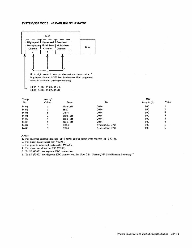
SYSTEM/360 MODEL 44 CABLING SCHEMATIC
2044
~i9h-Spee;r H igh-S;ed Tsta~ard--' I Multiplexer I Multiplexer I MUltiPlexer,
I Ch~nnel I Ch~nnel I Channel I
~~------_ r------~/ - V
1052
Up to eight control units per channel; maximum cable iii
length per channel is 200 feet (unless modified by general control-to-channel cabling schematic)
_ 44-01,44-02,44-03,44-04, 44-05, 44-06, 44-07, 44-08
Group No. of No. Cables From
44-01 1 Non-IBM 44-02 1 IBM 44-03 5 2044 44-04 3 Non-IBM 44-05 4 Non-IBM 44-06 5 Non-IBM 44-07 1 2044 44-08 1 2044
Notes:
To
2044 2044 2044 2044 2044 2044 System/360 CPU System/360 CPU
1. For external interrupt feature (SF #3895) and/or direct word feature (SF #3288). 2. For direct data feature (SF #3275). 3. For priority interrupt feature (SF #5625). 4. For direct word feature (SF #3288). 5. To SF #3621, two-system EPO connection.
Max Length (ft) Notes
100 1 100 1 100 4 100 3 100 2 100 4 100 5 100 6
6. To SF #3622, multisystem EPO connection. See Note 2 in "System/360 Specification Summary."
System Specifications and Cabling Schematics 2044.2

SVSTEM/360 MODEL 60 F, G, AND H, 2060 PROCESSING UNIT
PLAN VIEW
1 5/ 8,,-+-+I (All End T Covers)
f--29"
~ 2" I (4 Places)
L-s---
Frame Table
Ib kg
01 175 80 02 03
1 I I 1 I
1-7/8" / 29" ----!~---+I (4 Places) /
,/ (2 Places)
2-1/2"
i-----~H=~~+h===::::t-::::.:::=*t : 20"
L _____ :--___ ,----===::::-====*~ r---r----l Front r----"F---, 'Forms I I I I I ICarrieri I
_--55-1/2"--~---
Frame Covers
Ib kg Ib kg
1,900 870 200 91 1,150 530 250 120 1,560 710 150 69
2050.1 Installation Manual-Physical Planning

SYSTEM/360 MODEL 50 F, G, AND H, 2050 PROCESSING UNIT
SPECIFICATIONS
Dimensions:
F S H
Inches * * 72-1/2 (cm) (*) (*) (184)
Service Clearances:
F R Rt L
Inches * * * * (cm) (*) (*) (*) (*)
Models Weight: FandG H
lb 4,700 5,385 (kg) (2.150) (2.450)
Heat Output: BTU/hr 20,410 21,350 (kcal/hr) (5.150) (5.400)
Airflow: cfm 2,350 2,990 (m3/min) (67) (85)
Power Requirements: kVA 6.5 6.8 Phases 3 3 Plug R&S, SC7328 Connector R&S, SC7428 Receptacle R&S, SC7324 Power Cord Style E3
Notes: * See plan view.
System Specifications and Cabling Schematics 2050.2

SYSTEM/360 MODEL 50 HG AND I, 205O-PROCESSING UNIT
PLAN VIEW
I (2 Places) T
I (8 Places) (4 Places) ~ 5-3/8"
(4 Places)
i[29-;"f24"fl~---1 I 2-3/4" r 30" 3-3/8" I
,-~ - ~ 9 ~I==:::(:::~-==-=-=:"::; -6- - - 'e-l 1 @) I i 43"n I 29-1/2" 27" I (5 Places) (2 Places)
tl j-....... ,'- 6
j3" J/---j----+-
\+5-3/8" / I J ,-2-3/4" , (4 Places) I I '(4 Places)
I I ~ I I I -L----L--~..=~==:r_JI.....L,;;~_~:___----!---'--~+----__ 1._ +' 3-3/4"
I ~ (4 Places)
J @ :~ 24"
I ! _________ ~---,....__L-..L.
1--29" ---f-=--=~~~=~ 2-3/4" 1 f
' I \ / t 2" I / \, (4 Places) ,I __ / J', l
- / ....... -1 I L_--e- 25" / 60" ~~~~ / I
I 44-5/8" 1-7/8" /"~---58-1/2"---4_1 - -(4 Places) f (2 Places) I I
I ~ I
: r---- I ~ I 2" ~ I L_____ I I r---f----l I I : Farms I 'I I
C - I I
I I orner I I 29-1/2" I I I! L ___ J J L '-___ J! I
f ~---- ----~
C-=~-Ifi" ~'I. ~7_'fi" L20~ __ j' __ j Nate: Frame 05 may be used on some Model I systems.
Table Frame Covers Frame
Ib kg Ib kg Ib kg
01 175 80 1,900 870 200 91 02 1,150 530 250 120 03 1,560 710 150 69 04 1,500 690 250 120 05
2050.3 Installation Manual-Physical Planning
SYSTEM/360 MODEL 50 HG AND I, 2050 PROCESSING UNIT
SPECI FICATIONS
Dimensions:
F S H
Inches * * 72-1/2 (cm) (*) (*) (184)
Service Clearances:
F R Rt L
Inches * * * * (cm) (*) (*) (*) (*)
Weight: 7,1351b (3.250 kg)
Models
Heat Output: HG I BTU/hr 24,000 25,000 (kcal/hr) (6.050) (6.350)
Airflow: cfm 4,600 4,600 (m3/min) (140) (140)
Power Requirements: kVA 7.0 7.6 Phases 3 3 Plug R&S, SC7328 Connector R&S, SC7428 Receptacle R&S, SC7324 Power Cord Style E3
Notes: * See plan view.
System Specifications and Cabling Schematics 2050.4

SYSTEM/360 MODEL 50 CABLING SCHEMATIC
50-04
2361
Group No.
SO-OI SO-02 SO-03 SO-04 SO-06 SO-07 SO-08 50-09 SO-1O SO-l1 SO-12
Notes:
50-01 , 50-07
~
Other 2361s
No. of Cables
7 2 2 7 2 2 1 2 2
50-07
Storage
Sequence andControl (EPa)
From
2361 . Direct Control 20S0 2361 2050 2361 System/360 CPU 2050 20S0 20S0 20S0
2050
50-11 , 50-12 ...
50-02, 50-08
I I Selector Multiplexer Channel
Chatnne~~::.,:; 2 ~~::.,:; Channel-to-Channel ,1 3
Adapter J'
t
To
20S0 20S0 Control Unit 2361 Selector Channel 20S0 2050 Multiplexer Channel
50-03 50-06 50-09 50-10
Channel-to-Channel Adapter System/360 CPU System/360 CPU
Max Length (ft)
20 SO
100
100 100
1. For channel-to-channel adapter (SF # 18S0). Total cable length of 200 feet (unless modified by general control-to-channel cabling schematic) available to attach up to eight control units.
2. One per 2361. 3. To other System/360 CPU (SF #3274); order one per feature. 4. For SF #3274 from non-IBM device. S. The sum of groups SO-07 and (SO-OI plus SO-04) should not exceed ISO feet for any 2361. 6. To SF #3621, two-system EPO connection. 7. To SF #3622, multisystem EPO connection. See Note 2 in "System/360 Specification Summary."
Notes
S -4
1 S 1 2,S 3 1 1 6 7
System Specifications and Cabling Schematics 2050.5

SYSTEM/360 MODEL 65 H AND 1,2065 PROCESSING UNIT
PLAN VIEW
Frame Weight
Ib kg
01 2,400 1.100 02 1,020 470 04 540 250 06 330 150
2065.1 Installation Manual-Physical Planning

SYSTEM/360 MODEL 65 H AND I, 2065 PROCESSING UNIT
SPECI FICATIONS
Dimensions:
F S H
Inches • • 72-1/2 (cm) (*) (*) (184)
Service Clearances:
F R Rt L
Inches * * * * (cm) (*) (*) (*) (*)
Weight: 4,2901b (1.950 kg)
Heat Output: 15,800 BTU/hr (4.000 kcal/hr)
Airflow: 2, 100 cfm (60 m3/min)
Power Requirements:
kVA 5.4 Phases 3 Plug R&S, SC7328 Connector R&S, SC7428 Receptacle R&S, SC7324 Power Cord Style E I
Notes: * See plan view.
System Specifications and Cabling Schematics 2065 .2

SYSTEM/360 MODEL 65 IH AND J, 2065 PROCESSING UNIT
PLAN VIEW
I. 270-1/2" ·1 -,------,,-1- - - - ---B--- -----------B---- --------B- - - - -11 r i I
\0" ~ r-:r""" T, ~ ~(:::::.':::o~~ :::::Od ~I tl 57"
t I I , \ //, I II (4 Places) 17" : : \/: l * I r----.Ll------J---ll--1+- -~~ * ----------
I I @ I I 1"-' II III II 3-3/4" (Frames 08 and 10)
I 2365-2 ~ (I
I I ~ II I 4 Paces) I II I
I l _____ l _____ (~~~:e~ ____ -1 :: :
I I I (See Nate) II I ;---.-'-, I II I
~ 1 I 'A1~ernate I I I
34" I r...J \ : \- 2-3/4" (Frames 04 and 06)
4-1 : : \ / 1+ t l (4 Places)
. : ! \ I +T+ - 5-1/2" .----~----r..l-.l...------L----l---L-4 I l --- ____ (4 Places)
II ~ I n~~ I I ~ I 3" I I \
,---, 1-7/8" i Farms I r (4 Places) I Carrier I
r---~I I I I I I I I I
I
I
I
I
+
I
I
1
I
I I ,\ I I I \
I I I I ,
(4 Places) 1 I
~i_2" -1-1 -+1-+T+I---+-+--------'---~
L ___ .J 67-1/2" I
I I / \ I I / \ l...J ...... ./ "
" r- --, ......... I I',
r-' I I ,
-L __ oJ
12+ M
Fran t r I
@~ 2065
18+ i ..... J ", /~r ~ -H I: '\ / : :
I
I
.-___ -.-1-: --'-1 ____ \-'-./_---': ........... :----4 ~- - -++-1--+-+--- - ~/ 1----""1'----1r-20"i
@ / I I,----r--. 2365-2
I
t 1 I j, [ I I Altef,nate I +
34" I I // I
I
L~~/ \ r-J I
"'-, l :
+
I 2"~'-- I I @ / I II : 20"
I I I 1 I / L--~L,_---,-J----.t
+ +1
I I I I
L J ___ ~ I Forms I : Carrier:
- -----L ___ J
I r _____ T _________ ::::-~=~J~ I
I I @ I
1 8" x 10" (See Nate) : ~ (5 Places)
I I I I I I
I I
/1 ~. I
@! 2365-2
I I I
I I (See Nate) , ,
I
1
t I I
r I
I
I
60-3/4"
43"
43"
43"
60-3/4"
I I I 'I
L _____ .li -:---1------i T--L±" __ ~ __ +J _____ _ t 1 :: '\ I I I
- --------- - --+-1--
17" :: /\ : : ~ I I I / , I I
10" " , I
Frame Weight
Ib kg t f L..J ~/ \ r -l I
',I I ., • .---I'-----------------"'''L _...J Note: Add either storage unit for I 57"
I Model I H; add both sto.age units
---1---!.3l_" l _____ -e-- ____ ------e- _for Made_I J. __ ----B--------Ll 01 2,400 1.100 02 1,020 470 04 540 250 06 330 150 08 450 210 10 450 210
~30"_.l._22" .1. 62-1/2" .. I. 25-1/2" .. f. 62-1/2" I I. 20" .. I. 48,,----1
2065.3 Installation Manual-Physical Planning
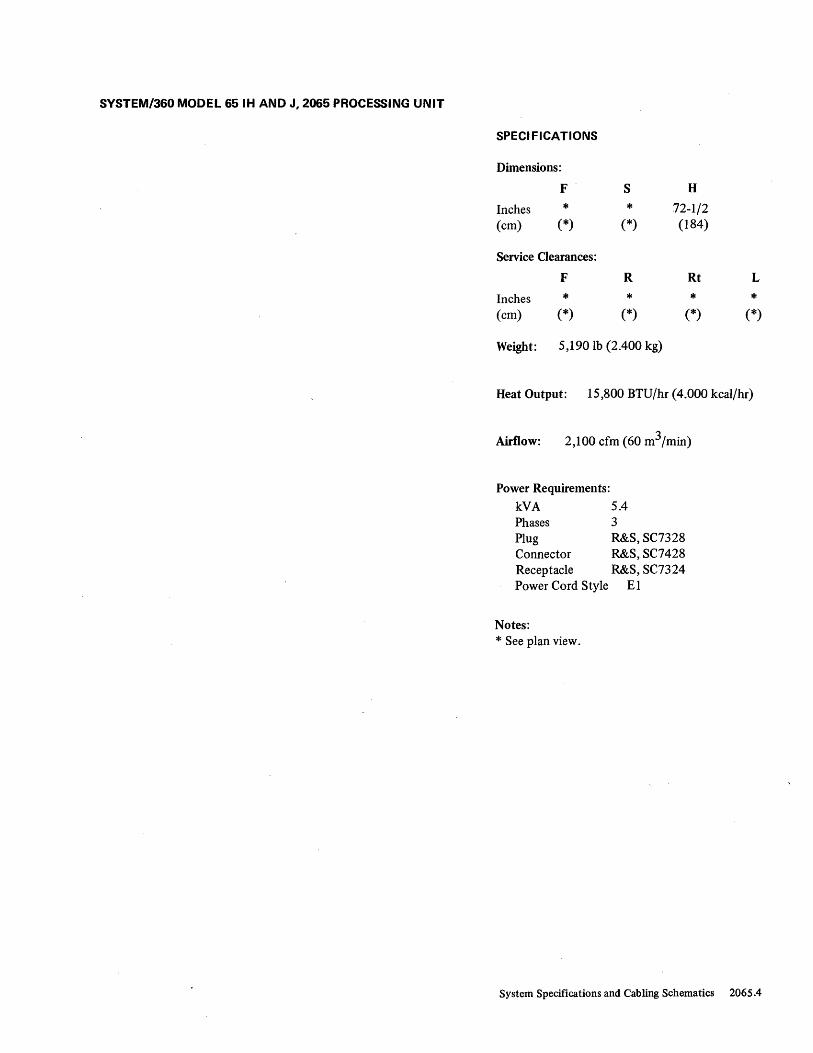
SYSTEM/360 MODEL 65 IH AND J, 2065 PROCESSING UNIT
SPECIFICATIONS
Dimensions:
F S H
Inches * * 72-1/2 (cm) (*) (*) (184)
Service Clearances:
F R Rt L
Inches * * * * (em) (*) (*) (*) (*)
Weight: 5,190 lb (2.400 kg)
Heat Output: 15,800 BTU/hr (4.000 kcal/hr)
Airflow: 2,100 cfm (60 m3/min)
Power Requirements:
k"~ 5.4 Phases Plug Connector Receptacle Power Cord Style
Notes: * See plan view.
3 R&S, SC7328 R&S, SC7428 R&S, SC7324
El
System Specifications and Cabling Schematics 2065.4

SYSTEM/360 MODEL 65 I, MULTIPROCESSING UNIT
PLAN VIEW
�"".c----------------------- 270-1/2" ---------------------~·I
--.----i ----G- - - - - - - - -0- - - - - - - - ~- - - - - - - - -<>- - .-~ ~-;~~~)- -0- - - - - -:1 I r-'-_ "r· I- 7/ 8 " ;----1 I I I ' , (4 Places) : Form,s : III
335"
2065.5
I I" I Comer I
'I ! ", rL----l,---,-----, 9 •• 3-3/4" __ I '\ I: c:p
(4 Places) r: \ :: I
I
I I
• 3" \ I I
(4 PLlaces) t! \ L _____ J : I \ _ I
r + + : t \ I o+L...J f +0 ~M 67-12":
60"
I
I <P I
f\W • 3-5/8" I 43" ~----l"" ~ ~~65 (8 Places) tQj\ ~ I I" V l,-J '\ /-'--"""1 @ a+ r , +0 :
:1 \/!i + + :1 y: I r-----r'-~ --,-I ____ ..1."// __ __'1'--1...1 -I +- - - --+.~i~-=--=-+:':.~.LI-------J ... ;:----I..,.: --:''-------': -1-2- 0-"---,-----''-----:-1 ----ir-
E9 : l ~-3/4" / I i:-------r-. I
~ I I (4 Places) I I I 'I I
2365-@4 11 / I 2"-"::'- : 20" I HI I I I II I I Gl
I I / I I: :---.t T :: _/,/ L----.JLr----lJ I
I 9 I
43"
L_L-- I I I _:. __ - -+-1-------------------;.:----;:-----'-1 _--+-+ + L ____ -' I
I I I ----I I
C-:\ I I ~ : Frame 17 has drop-down I
8" r-~ :..--------- 17" x 34" (43 cm x 86 cm) I .---1', I Ii 6" x 6,,1 gate and requires' 36" (91 cm) 9 : :", I clearance from down position : .. _-J \ _-r--' 1 : for service. See photo, I
I I I
<p
I I
43"
i ! \ // ! i + 8" + ____ J :
r-___ -r~i~i ____ ,~\,I ___ --'i__'i'--~ +---l-+~--------------------------------r-_-_--_-_,-----------I'----r
I r -,- - :: I E9 I : "" I I I
I I I I
<I>
I I I I I
2365·13 H2 ~
I I, ::
t::\ I I', :: I I I' ,.J.----J,i I
~ :: \ I: <D I I \ : l 67-1/2":
! I } l: ~ ____ ~ I: \ __ L ____ --.J I
: I / \ I! + + :: \ : I I ,/ \ i I 0 + L.J + 0 _ L __ L-/ \ r-~: M:
43"
"" I:: f(W Front I .... L I ~ 2065 I 43"
8"Xl0"~ #2 @ 9
I 6
(4 Places) @ 0 + r., + 0 :
I :' I
I I
Frame
01 : : /: i,r-20"~ I 02 I I / I I I 04 I : ;' I 2,,-l~----:t I 11 : I /: I: : 20" l 12 540 250 I : / / I I, 'I I'
I :4 250 120 I : L ---- J ~- --- /---.1 I
J60
"
i • T ,,;,:,,;.,"';'"' (0"",,,,,", ""';og pod, ,0 fro.~ 01 ,", 11. L J - - l ~:::~ j ! I • Typical dimensions for casters on frames 02, 12, and 14. I
I • Typical dimensions for casters on fromes 04 and 17. I L ___ ~---------~---------~----------~-----------&-----~ l--30" +22" .1. 62-1/2" .1 .. 25-1/2" .1.. 62-1/2" .1. 20" .1.. 48" .1
Weight
Ib kg + +
2,400 1.100 • 1,020 470 540 250
2,400 1.100 1,020 470
Installation Manual-Physical Planning

SYSTEM/360 MODEL 65 I, MULTIPROCESSING UNIT
SPECIFICATIONS
Dimensions:
F S H
Inches * * 72-1/2
(cm) (*) (*) (184)
Service Clearances:
F R Rt
Inches * * * (cm) (*) (*) (*)
Weight : 8,170 lb (3.750 kg)
Heat Output: 15,800 BTU/hr per 2065 (4.000 kcal/hr per 2065)
Airflow: 2,100 cfm per 2065 (60 m3/min per 2065)
Power Requirements: kVA 5.4 per 2065 Phases 3
L
* (*)
Plug R&S, SC7328 } Connector R&S , SC7428 Per 2065
Receptacle R&S , SC7324 Power Cord Style El
Notes: * See plan view.
System Specifications and Cabling Schematics 2065.6

SYSTEM/360 MODEL 65 IH, MULTIPROCESSING UNIT
PLAN VIEW
r ~-~-I----e-----
I
I I I
dJ I
270-1/2" ---------------------------.!., -~---------&--------~---------~----1~ ,.
371"
2065.7
I
! I I
dJ I I I I I I I I I
<P I I I I I
I 9 I I
2365-13 #1
0+ r, I , I I 1 , 1 I , I /
/
1 --
/
I ---~---
53"
43"
43"
+0 , , I I
I , /
/ /
: :120"1 ! 1 li-----i-. I
I I: : I I 1 2"--.._ I 20" 1 1 " I I Gl 1 ': :~ T L-----JLr----1J I
'I I
43"
I I
;-- - -+-I-----------------i-l_-_-_-_-..../;-: ---------'-:--l~ + ----1 I
I I I
<p
I I I I I I
dJ I I I I I I
<b I I Frame
r - ---, r'-- _ :: I
: ", '- :: 1
I '- ,1----1,1 I : ' , : i 1
\ I I <p I \ I: I 1 \ :: 67-1/2" 1
I ! I I 1 I L ____ -' I
I:: ,'I + I + : / \ l! - ---.; : \ -- I
i: / \ 11
:1
~13" 0 + ~.J 1+ 0 '--M II L_J_-/ \ rr-" f -~: (4 Places) 1
I I ~ Front I "-,L ___ J 2065 I
8"xl0"-- #2 @ 9 Weight (4 Places) @ 0 + r, + 0 :
\ Ib kg + + :: I I
I 01 2,400 1'410700 I', 'I I I I I 1020 , I I :r-20"---,
: E '~~~ ~;~ : : /: 2"~~----:1 1
r---l', I I '-I I "-
i r-.J '\ //--r--l I I \ I :! +
r-___ ~i-Li----\L\,I--~:~:~4 +---l + E&
~@
o ! Frame 17 has drop-down 1
8"r: ~17"x34"(43cmx86cm} I .r--I-- 6" x 6,,1 gate and requir~s 36" (91 em) 9
I clearance from down positiol> 1. : for service. See photo. I ' 8" + ____ J :
1
43"
43"
43"
I ~~ ~:~~~ 1.!~~ : : II: :i l20" ? 1 14 ;~~ ~;~ : / ~----JL----J~ I
J60"
i • T ypl:ldlm'~IOO"O, 00"'" 0", ",,' I" P"''' 00 I'om" 01 ood 11. U - - l ~:,~ j : I • Typical dimensions fal castels on flames 02, 12, and 14. I
1 • Typical dimensions for casters on frames 04, 06, and 17. i L ___ ~---------~---------~----------~-----------&-----~
l--30" +22" .1.. 62-1/2" .. ~ 25-1/2" .1. 62-1/2" .1 .. 20" .1.. 48" .1
Installation Manual-Physical Planning

SVSTEM/360 MODEL 65 IH, MULTIPROCESSING UNIT
SPECIFICATIONS
Dimensions:
F S H
Inches * * 72-1/2 (cm) (*) (*) (184)
Service Clearances:
F R Rt
Inches * * * (cm) (*) (*) (*)
Weight: 8,500 lb (3 .900 kg)
Heat Output : 15,800 BTU/hr per 2065 (4.000 kcal/hr per 2065)
Airflow: 2,100 cfm per 2065 (60 m3/min per 2065)
Power Requirements: kVA 5.4 per 2065 Phases 3 Plug R&S, SC7328 } Connector R&S, SC7428 Receptacle R&S, SC7324
Per 2065
Power Cord Style EI
Notes: * See plan view.
L
* (*)
System Specifications and Cabling Schematics 2065 .8

SYSTEM/360 MODEL 65 J, MULTIPROCESSING UNIT
PLAN VIEW
I-~-~-r----e-----
270-1/2" '. . .\
-~---------&--------~---------~----1-r
407"
T I
I I I
d> I
r-- .... , _2-3/4" I 53"
..,1~.-"_+-_________ ! :J ''-, \ /_ :-1 (4P jlaces)1 ;~ 3/4" - ~(~-~ra:'~S) l T : : \ / :! t I (4 -Places) I ~_L_~ ___________ :! ' 1-'r-~-4--4-;-----------4~~------------I~-+
I ,..--_""_--,...J.'----I.' ___ ----11 __ ----1'----1'--I +fl'\7l +...,- ~ r·1-7/811 ;-- ---1 I I <I7 ~ - .... , (4 Places) : Farm.s : I I ,,' Carner,
I 2365-13 ~ ", ~--___.rL----l,- l d> #3 I : '" I "\ " I I @ \ :: I
43"
I \ L _____ J I
II I: i :::. - - - !+--;.'---;C-------i
l;--\ -t--IH- __ . ___ ~-------_+----'-I', _--+-
:' II , , +" of I :: / \ :: + , I LL/ \ roo J : 0 + L.....J + + 0 ~ M 67-1 2" :
I '-'-,:! ~ • 3-5/8" I I ....... :" ___ J 2065 (8 Places) I
q> r--- -1", #1 IQi\ q> I I" ~
I : ~_J '\ __ -..., ® 0 + r -, ,+ 0 I'
: I \ // : I
43"
, ' I / :: -I- + : I, I : I i I I 1-+------I-+--i-:--li-------/:--'--:L---......J:-,--20-,-'I------..lL-~!--+
I I / I ii-------:--. I
I 9 I I
2365-13 #1
, I ;' I I: : I I I I I I 2" _ ~- '20" I I , / I " 'I 9 , I // I ': :-----I.
43"
LJ.-- _ - L -- __ .JL: ____ :~ : !.-- - -:-+-----------------il-_-_-_-_-iJ-----.!...: ---l-+ ----I I
I I I I I
<p
I I I
I I I
cD
I
2365-13 #2
@ I Frame 17 has drop-down : 811 r: ~17Ix34"(43cmx86cm} I
,----- 6" x 6,,1 gate and requires 36" (91 cm) 9 1 clearance from dawn position
1.. I for service. See photo. I 8" + ____ J :
43"
I r----' r -,- - :: I I : """, :: I , I, " I I' ,-I.----.L,I I I I" : i I , I \ I' <D I I \ ': I
43"
I I , :: 67-1/2" I
Ii: : ~---'-! --'-:---------'\-- f- - - - -l_L_-_-_-_-_..J ___ -+-_.!...: --+-
,', " ' " I
I I
0+ L...J + 0 ~M I r-- : I
r----" " ....... -;-l __ ..J ~ 2065 Front :
: :"'B"xlO"-- #2 @ 9 : roo J (4 flaces/) /-I--:@o+r-,+ol : , \ / " J t---;'--'-, --------,.--+' I
I I I
<b I I
43"
: ! \ I I I +_.l __ ~ I I I I , : \, i! ++ -I- -1--+: -!-:-------:/~-!-: ------l:,-~--20-"-~------..lL-~,,----1!-• 3" , , I I I I
I
¢
I I
2365-13 #4
I I / I 2"~::':::"----:1 I ~'aces) ii/I: :: I 20" 1 ~ f::\ " / I II : I Y
L-----'-r--.------;----..,..-..,..--I ./ ; Farms : I + 0
~\+6 " " -- L ____ ..J~----.._'---1 I
, I , , L...J- - Weight 'Carrier I .. -----i i /\ : I ! t Frame Ib kg L ____ J : 13" ,: / \ ! :, 01 2,400 1.100 : -'*'--____________ ~_J __ ~- \ ,-_J, 8"x8" (2 Places) 02 1,020 470 I
I
43"
10" ",,: : Frames 06, 16, and 04 540 250 I -,-_-'--________________ '.......:::'-L ___ J 36 with Additional 06 330 150 I 53"
i )., Storage Feature 11 2,400' 1.100 I
..L.._30L"_~ _:_:;:~:~:;;:i:~; :;:; ;~;~:;; ~~j~~:~::~I~ ________ ! __ ~~ ___ 1~ ___ ~ _____ JJ 1.--30"~22" ~I- 62-1/2" .I.. 25-1/2" .1.. 62-1/2" .1.. 20" .1.. 48,,---J
2065.9 Installation Manua1~Physical Planning

SVSTEM/360 MODEL 65 J, MULTIPROCESSING UNIT
SPECI FICATIONS
Dimensions:
F S H
Inches * * 72-1/2 (cm) (*) (*) (184)
Service Clearances:
F R Rt
Inches * * * (cm) (*) (*) (*)
Weight : 8,8301b (4.050 kg)
Heat Output : 15,800 BTU/hr per 2065 (4.000 kcal/hr per 2065)
Airflow: 2,100 cfm per 2065
(60 m3/min per 2065)
Power Requirements: kVA 5.4 per 2065 Phases 3
L
* (*)
Plug R&S, SC7328 } Connector R&S, SC7428 Per 2065 Receptacle R&S, SC7324 Power Cord Style El
Notes : * See plan view .
System Specifications and Cabling Schematics 2065 .10

SYSTEM/360 MODEL 65 CABLING SCHEMATIC
,---I I I I I
60-20
20651,J
2065 H
@
60-31
60-31,60-32 60-12
I 2361 ,60-04
60-33
60-04, 60-05, 60-33
60-25 ~--------------~~ 60-09 (Note 16)
I 60-27 60-35
60-34 I 60-08 60-28
I ii I I I I I 2860 2860 2870 I
#1 60-10 #2 60-10 #1 I I 60-11 60-11 I
60-14 60-14 I 60-15 60-15 I L __________ ---~-~
2065.11 Installation Manual-Physical Planning
2870 #2
60-13 60-17 60-18 60-19 60-22 60-23 60-30
Additional 23615

SYSTEM/360 MODEL 65 CABLING SCHEMATIC
Group No. of No. Cables From To
60-03 1 2860 2065 (B) 60-04 1 2361 2065 H (B) 60-05 12 2361 #1 2065 H (B) 60-06 1 2860 #1 2065 (B) 60-08 13 2860#2 2860 #1 60-09 2 Direct Control 2065 (B) 60-10 2 2860 (SF #1850) Control Unit 60-11 2 2860 (SF #1850) Channel-to-Channel Adapter 60-12 12 2361 2361 #1 60-13 1 Direct Control 2065 (B) 60-14 2 2860 (SF #1850) Multiplexer Channel 60-15 2 2860 (SF #1850) Selector Channel 60-16 1 2860#2 2065 (B) 60-17 2 SF #7920/#7921 Selector Channel 60-18 2 SF #7920/#7921 Control Unit 60-19 2 SF #7920/#7921 Channel-to-Channel Adapter 60-20 13 2860#1 2065 (A) 60-22 1 2065 (B) System/360 CPU 60-23 1 2065 (B) System/360 CPU 60-25 13 2870 #1 2065 (A) 60-27 1 2870 2065 (B) 60-28 13 2870 #1 2860#2 60-29 1 2870#1 2065 (B) 60-30 2 SF #7920/#7921 Multiplexer Channel 60-31 1 2361 2065 I, J (C) 60-32 12 2361 #1 2065 I, J (C) 60-33 1 2361 2065 (B) 60-34 13 2870 #2 2870 #1 60-35 1 2870 #2 2065 (B)
Notes: 1. From channel-to-channel adapter (SF # 185 0). 2. One per channel. 3. The sum of group 60~20 plus 60-05 or 60-32 plus 60-08 plus 60-28 plus 60-34 plus 60-12(s) must
not exceed 140 feet for Models H and I; 120 feet for Model J. 4. One per 2361. 5. At no time may the sum of groups 60-20 plus 60-08 plus 60-28 plus 60-34 exceed 65 feet. 6. Sequence and control (EPO). 7. For the interconnection of two System/360 CPUs (SF #3274); order one per feature. 8. For the interconnection of two channel-to-channel adapter features (SF #1850). 9. Total cable length of 200 feet (unless modified by general control-to-channel cabling schematic)
available to attach up to eight control units. to. To SF #3621, two-system EPO connection. 11. For SF #3274 to non-IBM device. 12. To SF #3622, multisystem EPO connection. See Note 2 in "System/360 Specification Summary." 13. Maximum "X" length:
25 feet for one channel frame 45 feet for two ch~nnel frames 65 feet for three or four channel frames.
14. When used with 2870 #2 and 2870 #2 is the fourth channel frame, "X" length must equal sum of groups 60-20 plus 60-08 plus 60-28 plus 60-34; but length should not exceed 65 feet.
15. Use group 60-29 for 2870 #2 if total number of channel frames is less than four. 16. Use group 60-25 in place of groups 60-28 and 60-20 when 2870 is the only channel.
Max Length (ft)
50 50 20 40 20 50
20 100
25 100 100
25
20 65
20
20 65
Notes
2 4 3 6 3,5 11 1,9 8,9 3 7 1,9 1,9 6 9 9 9 3,5 10 12 16 13,14 3,5 6 9 4 3 4 5 6, 15
System Specifications and Cabling Schematics 2065.12

SVSTEM/360 MODEL ,65 MULTIPROCESSING CABLING SCHEMATIC
2365 #4
Irr~-....J I I I 60-20 60-03
60-06
60-08
60-03 60-16
2065 #2
60-28
60-27 60-29
2365 #1
60-34
~l
t I
I I
I
I I
2860 60-10 2860 60-10 2870 I #1 60-11 #2 60-11 #1
I 60-14 60-14 I 60-15 60-15
100~5 I (Note 14) ____________ ~
2065.13 Installation Manual-Physical Planning
2870 #2
Cables from 1/0 Device (SF #6148)
60-09 60-13 60-17 60-18 60-19 60-22 60-23 60-30
2870 #2
60-34
60-27 60-29
60-28
60-03 60-16
60-03 60-06
60-08
-l I I
00-20 t I
I I
II I
II 60-10 60-10 I
2870 60-11 2860 60-11 2860 I
I
#1 60-14 #2 60-14 #1
60-15 60-15 I L 60-25
_____________ (Note 1~

SYSTEM!360 MODEL 65 MULTIPROCESSING CABLING SCHEMATIC
Group No. of No. Cables From To
60-03 2860 2065 60-06 1 2860 #1 2065 60-08 13 2860 2860 #1 60-09 2 Direct Control 2065 60-10 2 2860 (SF #1850) Control Unit 60-11 2 2860 (SF #1850) Channel-to-Channel Adapter 60-13 1 Direct Control 2065 60-14 2 2860 (SF #1850) Multiplexer Channel 60-15 2 2860 (SF #1850) Selector Channel 60-16 1 2860 #2 2065 60-17 2 SF #7920/# 7921 Selector Channel 60-18 2 SF #7920/#7921 Control Unit 60-19 2 SF #7920/#7921 Channel-to-Channel Adapter 60-20 13 2860 #1 2065 60-22 1 2065 System/360 CPU 60-23 1 2065 System/360 CPU 60-25 13 2870#1 2065 60-27 1 2870 2065 60-28 13 2870 #1 2860#2 60-29 1 2870 2065 60-30 2 SF #7920/#7921 Multiplexer Channel 60-34 13 2870 #2 2870 #1 60-35 1 287') #2 2065 #1
Notes: 1. From channel-to-channel adapter (SF #1850). 2. One per channel. 3. When 2365 #4 is absent, rQute the cables to cable entry F instead of A. 4. When 2365 # 3 is absent, route the cables to cable entry G instead of E. 5. At no time may the sum of groups 60-20 plus 60-08 plus 60-28 plus 60-34 exceed 65 feet. 6. Sequence and control (EPO). 7. For the interconnection of two System/360 CPUs (SF #3274); order one per feature. 8. For the interconnection of two channel-to-channel adapter features (SF #1850). 9. Total cable length of 200 feet (unless modified by general control-to-channel cabling schematic)
available to attach up to eight control units. 10. To SF #3621, two-system EPO connection. 11. For SF #3274 to non-IBM device. 12. To SF #3622, multisystem EPO connection. See Note 2 in "System/360 Specification Summary." 13. Maximum "X" length:
25 feet for one channel frame 45 feet for two channel frames 65 feet for three or four channel frames.
14. Use group 60-25 in place of groups 60-28 and 60-20 when 2870 is the only channel. 15. When used with 2870 #2 and 2870 #2 is the fourth channel frame, "X" length must equal sum of
groups 60-20 plus 60-08 plus 60-28 plus 60-34; but length should not exceed 65 feet. 16. Use group 60-29 for 2870 #2 if total number of channel frames is less than four on 2065 # 1.
Max Length (ft) Notes
50 2 40 6 20 5 50 11
1,9 8,9
100 7
25 100 100
25
20 65
20 65
1,9 1,9 6 9 9 9 3,4,5 10 12 14 13, 15
6 9 5 6, 16
System Specifications and Cabling Schematics 2065.14

SYSTEM/360 MODEL 67 CONFIGURATIONS
The IBM System/360 Model 67 configuration varies, depending on the units that are ordered by the customer to make up his system.
The following rules are to be observed in the arrangement of the system and peripheral units: 1. The configurations of the System/360 Model 67-1 are
limited by features to those shown on the following page. The IBM 2365 Processor Storage units are to be numbered as shown in Examples 12 through 15.
2. The configurations of the System/360 Model 67-2 are shown on Examples 16 through 23. The 2365 Processor Storage units and 2067 Processing Units are to be numbered as shown in Examples 16 through 23. The 2365 Processor Storage units in Example 23 would always be numbered 5· through 8 from left to right,
2067:1 Installation ManUal-Physical Planning
regardless of whether the configuration was located to the left or right of the configuration with the processors.
3. The 2365 Processor Storage units are installed to the right and/or left of the 2067 or side by side in a contiguous wall. section with an expansion feature (SF #3846) between them. This feature (SF #3846) must always be between two adjacent 2365 units when a 2067 is not between them.
4. The 2365 Processor Storage Model 2 units require SF #8035 when installed with a 2067.
5. The power sequence feature (SF #5518) is required for a system with two or more 2067 Processing Units. SF #5518 is installed in one of the expansion features (SF #3846) that will be required for the two-processor system.
6. Sub floor cable entry capability is a requirement.

SYSTEM/360 MODEL 65 J MULTIPROCESSING ADDITIONAL STORAGE FEATURE CABLING SCHEMATIC
, I
60-43 60-44 60-46 60-48 60-50
2365-13 #5
I I
~ @
- -·2365-13 r 2365-13 r-
#6 #7
I I
@ 0 @ @ @
'-60-53-
- 60-52 -----' L...--_+-- 60-55 -(or 60-57)
'--60-53 ------+-----.
'-----+----60-53 -------------t-----,
'-60-52 - ,--------------60-52-
-2365-13
#8
@
-60-53-
" -60-54-
(or 60-56) ~-------60~2----------~~++-------J
2365-13 #4
I A I
,..-__ ---, Cables from I/O Device
2365-13 (SF #6148) #1 ,~
2365-13 #2
2365-13 #3
I E I
" 60-42 60-45 60-47 60-49 60-51
'--rEJ @ @) e G-
2065 #2
2065.15 Installation Manual-Physical Planning
Ir'-'-~D"""""I
2065 #1

SYSTEM/360 MODEL 65 J MULTIPROCESSING ADDITIONAL STORAGE FEATURE CABLING SCHEMATIC
Group No. of From To No. Cables Un it·Frame Uflit-Frame
60-42 12 2365-13 Fr 36 2065 Fr 06 60-43 12 2365-13 Fr 36 2065 Fr 16 60-44 3 2365-13 Fr 36 2065 Fr 16 60-45 3 2365-13 Fr 36 2065 Fr 06 60-46 3 2365-13 Fr 36 2065 Fr 16 60-47 3 2365-13 Fr 36 2065 Fr 06 60-48 3 2365-13 Fr 36 2065 Fr 16 60-49 3 2365-13 Fr 36 2065 Fr 06 60-50 3 2365-13 Fr 36 2065 Fr 16 60-51 3 2365-13 Fr 36 2065 Fr 06 60-52 1 2365-13 2065 Fr 12 60-53 1 2365-13 2065 Fr 02 60-54 (or 60-56) 1 2365-13 Fr 36 2065 Fr 12 60-55 (or 60-57) 1 2365-13 Fr 24 2065 Fr 02
Notes: 1. These cable groups are required for lust additional storage unit.
Max Length (ft) Notes
35 1,2 35 1,2 35 1,2 35 1,2 35 2,3 35 2,3 35 2,4 35 2,4 35 2,5 35 2,5 60 6 60 6 40 7,9 40 8,9
2. Total "X" length must not exceed 50 feet for cable groups (60-42 plus 60-43), (60-44 plus 60-45), (60-46 plus 60-47), 60-48 plus 60-49), and (60-50 plus 60-51).
3. These cable groups are required for second additional storage unit. 4. These cable groups are required for third additional storage unit. 5. These cable groups are required for fourth adG-~tional storage unit. 6. One cable group is required for each additional storage unit. 7. One cable group is required for lust additional storage unit. 8. One cable group is required for third additional storage unit. 9. For 50-Hz machines, use group number in parentheses.
System Specifications and Cabling Schematics 2065.16

SYSTEM/360 MODEL 67 CONFIGURATION FEATURES
The IBM Sales Manual lists the special features that must be ordered to make up the various configurations of the 2365 Processor Storage units and the 2067 Processing Units.
System/360 Model 67·'
2365 #1
SF #9101
2067
Example 12-SF #9101 attaches 2365 Model 2 #1 to 2067 Model 1. ./
2365 2365 #1 #2
SF #9101 SF #9102
2067
2365 #3
SF #9103
2365 2365 2365 #3 #1 #2
SF #9103 SF #9101 SF #9102
2067
Example 14-'SF #9103 attaches 2365 Model 2 #3 to
2365 #1
SF #9101
2067 Model 1 (2365 Model 2 with SF #9102 is a prerequ isite).
2365 2365
#2 #4
SF #9102 SF #9104
2067
Example 13-SF #9102 attaches 2365 Model 2 #2 to 2067 Model 1
Example 15~SF #9104 attaches 2365 Model 2 #4 to 2067 Model 1 (2365 Model 2 with SF #9103 is a prerequisite).
(2365 with SF #9101 is a prerequisite).
System Specifications and Cabling Schematics 2067.2

System/360 Model 67-2
The following feature listing and example represent typical configurations:
Special Feature (SF#)
9111 *
9112*
9114*
·9116*
9117
9118
9119
9121*
9122*
9123*
9125*
2846 #1
Function
Required to attach 2365 Model 12 # 1 to 2067 Model 2 # 1. Plant installation only.
Required to attach 2365 Model 12 #2 to 2067 Model 2 # 1. Plant installation only.
Required to attach 2365 Model 12 #3 to 2067 Model 2 # 1. Plant installation only.
Required to attach 2365 Model 12 to #4 to 2067 Model 2 # 1. Plant installation only.
Required on the right-end 2365 of the second wall to connect 2067 # 1 from the right.
Required on the left-end 2365 of the second wall to connect 2067 # 1 from the left.
Required on each 2365, except the first of the second wall, for 2067 # 1. Prerequisite is either SF #9117 or SF #9118 on the first 2365.
Required to attach 2365 Model 12 #3 to 2067 Model 2 #2.
Required to attach 2365 Model 12 #4 to 2067 Model 2 #2.
Required to attach 2365 Model 12 #.2 to 2067 Model 2 #2.
Required to attach 2365 Model 12 # 1 to 2067 Model 2 #2.
2365 #5
SF #9119 SF #9131 SF #9129 SF #9143
Second Wall
2365 #6
SF #9117 SF #9133 SF #9127 SF #9142
First Wall
2365 #1
SF #9111 SF #9131 SF #9125 SF #9143
2067.3 Installation Manual-Physical Planning
Special Feature (SF#) Function
9127 Required on the right-end 2365 of the second wall to connect 2067 #2 from the right.
9128 Required on the left-end 2365 of the second wall to connect 2067 #2 from the left.
9129 Required on each 2365, except the first of the second wall, for 2067 #2. Prerequisite is either SF #9127 or SF #9128 on the fIrst 2365.
9131 Required on the left-end 2365 of each wall when 2846 # 1 attaches on the left.
9132 Required on the right-end 2365 of each wall when 2846 # 1 attaches on the right.
9133 Required on each 2365 on a wall, except the first, for 2846 #1. Prerequisite is either SF #9131 or SF #9132 on the first 2365 on each wall.
9141 Required on the left-end 2365 of each wall when 2846 # 2 attaches on the left.
9142 Required on the right-end 2365 of each wall when 2846 # 2 attaches on the right.
9143 Required on each 2365 on a wall, except the rust, for 2846 #2. Prerequisite is either SF #9141 or SF #9142 on the first 2365 on each wall.
*Model12 only.
2365 2365 #2 #3
2846#2 -SF #9112 SF #9114
2067 SF #9133 SF #9133 2067 #1 SF #9123 SF #9121 #2
SF #9143 SF #9142

System/360 Model 67-2 Configurations With One Processor
2365 #1
Example 16
2365 #1
Example 17
2067 #1
2067 #1
2365 #2
2365 #3
System/360 Model 67-2 Configurations With Two Processors
2067 #1
Example 20
2365 #1
Example 21
2365 #2
2067 #1
2365 #2
2365 #3
2067 #2
2365 #3
2067 #2
2365 #4
Note: Additional 2365 Processor Storage units (maximum of four) may be ordered with any of the two-processor configurations.
2365 #1
Example 18
2365 #1
2067 #1
2067 #1
Example 19
2365 #1
2067 #1
Example 22
2365 #5
Example 23
2365 #2
2365 #2
2365
#2
2365 #6
2365 #3
2365 #3
2365 #7
2067 #2
2365 #4
2365 #8
System Specifications and Cabling Schematics 2067.4

SYSTEM/360 MODEL 67,2067 PROCESSING UNIT
PLAN VIEW
,---- e- - - - -e - -€) - - - - (7- - I r-- 30" -~---45"
I I
I I 9 I I I
<b I I I I ? I I I 6 I I I I I 9 I I I I I
q> I I I L __ _
14"-+--+1
+ 15" x 12"
/--
/' V 36"
r-----------1 1- _________ _
r---------- -L _________ _
1----------- -----1 1 ______ -- ______ _
Frame Weight
Ib kg
01 1,914 870 02 860 400 03 900 410
43"------+l~-- 45" ---.+_---l-- 30"-1
5-7/16" (4 Places)
- - - - - - - - - - - - - --I 1 --------------,
30"
24"
38-3/4"
I I
I
? I I
I ~ I I I 9
¢
I I I I 9
2067.5 Installation Manual-Physical Planning

SYSTEM/360 MODEL 67, 2067 PROCESSING UNIT
SPECIFICATIONS
Dimensions:
F S H
Inches * * 72-1/2 (cm) (*) (*) (184)
Service Clearances:
F R Rt L
Inches * * * * (cm) (*) (*) (*) (*)
Weight: 3,6741b (1.700 kg)
Heat Output: 20,000 BTU/hr (5.050 kcal/hr)
Airflow: 4,620 cfm (140 m3/min)
Power Requirements: kVA 6.85 Phases Plug Connector Receptacle Power Cord Style
Notes:
3 R&S, SC7328 R&S, SC7428 R&S,SC7324
El
* See plan view. Dimensions are frame s~e; add 1-3/8~' (4-cm) for each -cover.
System Specifications andCa!>ling Schematics 2067~-6

SYSTEM/360 MODEL 67-1 CABLING SCHEMATIC
67-10 67-11
60-06 67-37
2365-2
\
2365-2
60-20 60-16"<_ 60-25 (Note 9) 67-37 -----~__,
60-28 I I
2860 60-10 60-10 60-11 2860
60-11 #1 60-14 #2 60-14
60-15 60-15
2067.7 Installation Manual-Physical Planning
60-29 67-36 67-36
67-38
60-34
2870 2870 #1 #2

SYSTEM/360 MODEL 67-1 CABLING SCHEMATIC
Group No. of No. Cables From To
60-06 1 2860 #1 2067 60-08 13 2860#2 2860#1 60-10 2 2860 (SF #1850) Control Unit 60-11 2 2860 (SF #1850) Channel-to-Channel Adapter 60-14 2 2860 (SF #1850) Multiplexer Channel 60-15 2 2860 (SF #1850) Selector Channel 60-16 1 2860#2 2067 60-20 13 2860 #1 2365-2 60-25 13 2870 #1 2365-2 60-28 13 2870 #1 2860#2 60-29 1 2870 #1 2067 60-34 13 2870#2 2870 #1 67-10 1 Direct Control 2067 67-11 2 Direct Control 2067 67-20 2 SF #7920 2860 67-21 2 SF #7920 Control Unit 67-22 2 SF #7920 Channel-to-Channel Adapter 67-35 2 SF #7920 2870 67-36 1 2870 2067 67-37 1 2860 2067 67-38 1 2870#2 2067
Notes: 1. From channel-to-channel adapter (SF #1850). 2. One per channel. 3. At no time may the sum of groups 60-20 plus 60-08 plus 60-28 plus 60-34 exceed 65 feet. 4. Sequence and control (EPO). 5. For the interconnection of two System/360 CPUs (SF #3274); order one per feature. 6. for the interconnection of two channel-to-chan~el adapter features (SF #1850). 7. Total cable length of 200 feet (unless modified by general control-to-channel cabling schematic)
available to attach up to eight control units. 8. Maximum "X" length:
25 feet for one channel frame 45 feet for two channel frames 65 feet for three or four channel frames.
9. Use group 60-25 in place of groups 60-28 and 60-20 when 2870 is the only channel. 10. For SF #3274 to non-IBM device. 11. When used with 2870 #2 and 2870 #2 is the fourth channel frame, "X" length must equal sum of
groups 60-20 plus 60-08 plus 60-28 plus 60-34; but length should not exceed 65 feet. 12. Use group 60-29 for 2870 #2 if total number of channel frames is less than four.
Max Length (ft)
40 20
25 25 20
100 50
Notes
4 3 1,7 6,7 1,7 1,7 4 3 9 3 4 3 5 10 7 7 7 7 8,11 2 4, 12
System Specifications and Cabling Schematics 2067.8

SYSTEM/360 MODEL 67-2 CABLING SCHEMATIC
67-27 67-28
67-02 67-08
Group No.
60-08 60-10 60-11 60-14 60-15 60-22 60-23 60-28 67-02 67-03 67-04 67-05 67-06 67-07 67-08 67-09 67-12 67-14 67-15 67-16 67-17
\ \
2365-12 \ \
67-14
2846 ~---------------67~3
No. of Cables From
13 2860 #2 2 2860 (SF #1850) 2 2860 (SF #1850) 2 2860 (SF #1850) 2 2860 (SF #1850) 1 2067 1 2067
13 2870 3 2846 3 2846
14 2860#1 1 2860 1 2860
12 2365-12 1 2846
2846 2067 1846 2365-12 2365-12 2846
2067.9 Installation Manual-Physical-Planning
67-20 67-21 67-22 67-35
67-14
67-19
2870
To
2860#1 Control Unit
67-05 67-06
Channel-to-Channel Adapter Multiplexer Channel Selector Channel System/360 CPU System/360 CPU 2860#1 2067 2846 2846 2846 2846 2365-12 2067 2365-12 Sequence Control (SF #5518) Sequence Control (SF #5518) Sequence Control (SF #5518) 2067 2067
67-04 67-05 67-06
2860 #1
Max
60-10 60-11 60-14 60-15
Length (ft)
20
20 100 100
20 40
115 25 35
30 100 125 45 60 60 60 60
67-24
2846
67-02 67-08
67-09 67-27 67-28
Notes
7 9,10 9, 10, 11 9, 10 9, 10 24 25 7 19 2 8 3 4 5 6 12 13-15 16 17 18

SYSTEM/360 MODEL 67·2 CABLING SCHEMATIC
Group No. of No. Cables From To
Max Length (ft)
67-18 13 2870 2846 67-19 2 2870 2846 67-20 2 2067 (SF #7920) Selector Channel 67-21 2 2067 (SF #7920) Control Unit 67-22 2 2067 (SF #7920) Channel-to-Channel Adapter 67-23 1 2067 2067 67-24 1 2365-12 2067 67-25 (or 67-98) 1 2365-12 2365-12 67-27 11 2846 2365-12 67-28 11 2846 2365-12 67-31 11 2365-12 2365-12 67-32 11 2365-12 2365-12 67-35 2 2067 (SF #7920) Multiplexer ~hannel
Notes: 1. May connect to first 2365 at either end of the system wall. 2. Total cable length to attach up to three 2846 units is 115 feet. One group 67 -03 is required for each
2067 connected to the 2846s. 3. Sequence and control (EPO). 4. One per channel. Maximum cable length of 25 feet to first channel frame; 85 feet to any other channel. 5. May be used to connect one contiguous wall section to another. One group 67 -07 is required for each
2067 in the configuration. 6. One to each 2067. 7. Channel-frame-to-channel-frame interconnecting cable length should not exceed 60 feet for up to three
channel frames. 8. Cable length from 2846 to first channel should not exceed 25 feet. 9. From channel-to-channel adapter (SF #1850).
10. Total cable length of 200 feet (unless modified by general control-to-channel cabling schematic) available to attach up to eight control units.
11. For the interconnection of two channel-to-channel adapter features (SF # 185 0). 12. One to each 2365.
75
25 25 45 45
13. Multisystem EPO connection (SF # 3622); one per 2067 .. See Note 2 in "System/360 Specification Summary." 14. May be used to connect one contiguous wall section to another. Use group 67-31 for 2846 #1 and group
67-32 for 2846 #2. 15. One per 2846. Power sequence (EPO). 16. One per 2365 in multiple 2067 system. Power sequence (EPO). 17. One per 2365 in single 2067 system. Power sequence (EPO). 18. Required -vhen system has 2365 Model 12s and only one 2067. 19. All the 67-02 cable groups may be routed from anyone of the 2846 units to each 2067 in the system or
from separate 2846 units as shown. 20. One group is required between first 2067 and second 2067 when Doth have SF #3800 (extended direct
control feature). 21. Required for the connection of the 2365 s of one contiguous wall section to the 2067 s of a second contigu
ous wall section. One is required from each 2365 to each 2067. 22. Required to conn~ct second contiguous wall section with the first for convenience outlet power when
second wall section has no 2067. For 50-Hz machines, use group number in parentheses. 23. Maximum "X" length of group 67-23 cannot exceed 100 feet. 24 .. To SF #3621, two-system EPOconnection, to 2067 for single processor; SF #5518 for dual processor. 25. To SF #3622, multisystem EPO connection, to 2067 for single processor; SF #5518 for dual processor.
See Note 2 in "System/360 Specification Summary."
Notes
7,8 3,4,8 10 10 10 20,23 21 22 1 1 14 14 10
System Specifications and Cabling Schematics 2067.10

SYSTEM/360 MODEL 75 H AND I, 2075 PROCESSING UNIT
PLAN VIEW
I -.:. - --(7-- - - --0--- - - - --0- - - - -G- - - - -e - - - -0- -,-~
I 30" I
I I
r29-1/2"l
~ I I ~~r-fi-I // \il-
2365-3
I ~ [(~-:I~~; // /-/;:;nH-f I / f-, I: :
3-1/4" rl! I I '~L-I (S Places) 1 . 2-I/S";. L I I ~ ..i 1(4 Places, - n--
I t r-~O+ - 9"-+~ I ~ -..I 10" l-I 25-1/2·;r : I'vrr II r 1 I !1 I
I 1l!lI~ I L: ______ • I I S-1/2"t~.t~6':~O L ________ I @)l 'P I I
I 19": Spacer :
I L: ': :0-- - - - ;j------.-j
I I
I : 1052 I 2-3/4" 2S"
Note: Frame 1 1 is required for SF #7920 and #7921. '" ~ ~l-1/2_. ~----~i?~~:')
I : 1052 r (S Places)
I : 28-1/2" I !.? ______ oJ t L 30,,-.l-2S-3/4" .1.. 63"
,- - - -G- - --0- - - --B-
Weight Airflow Heat Output Frame
m3/min Ib kg cfm BTU/hr kcal/hr
01 1,700 780 1,700 49 13,800 3.500 02. 2,200 1.000 1,050 30 S,280 2.100 03 125 57 0 0 0 0 04 550 250 300 9 2,760 700 05 550 250 300 9 2,760 700 II 250 120 550 140
1052 100 46 335 85 Spacer 30 14
2075.1 Installation Manual-Physical Planning
~ ~
30"
2075
Front
30"

SYSTEM/360 MODEL 75 H AND 1,2075 PROCESSING UNIT
SPECI FICATIONS
Dimensions:
F S H
Inches * * 72-1/2 (cm) (*) (*) (184)
Service Clearances:
F R Rt L
Inches * * * * (cm) (*) (*) (*) (*)
Weight: 5,1251b (2.350 kg)
Heat Output: 27,600 BTU/hr (7 .000 kcal/hr)
Airflow: 3,350 cfm (95 m3/min)
Power Requirements: Voltage 208/230 220 408 kVA 8.6 6.9 11.2 Phases 3 3 3 Plug R&S, SC7328 Connector R&S, SC7428 Receptacle R&S, SC7324 Power Cord Style E3
Notes: * See plan view.
System Specifications and Cabling Schematics 2075 .2

~ o .....:I VI ~
a ~ Q' ::s S:'
~ e. L
~ ~. e.
J
r30"-T28-3/4" iort( 63" -I- 43-3/4" JOlt( 43-3/4" ~I'" 60" ~II( 63" t-33"-j I --0-- - - --tT- -- -- - --~ - - - -0--- - - -- -e- -- -- --e- -- -,O------r
- I I I I I I I
t I
I ~
2r-l ttl
19" I t-+
75-l/2't2~" I
8-1 28-1/2" 1
--I I I I
r--: 30"-----11" -I 18" I (8 Places) I (8 Places)
..-------;
ED
2365-3 ----f4-.- 2365-3 " /- r..l ----,r---,,/ \ _I I --, ,L __ _
/ \ : , L_-.l \ / " , / '--
ED
~---, i[--L '\-
_.--l '\ / "-
ED
2365-3 -, -, I
L_-1 /
/ / 1...., / ---~ /--nf- t... --'" ",/
l [5-11/16" I"'/' " --- /
(4 Places) / II /1 ':' ",\ I
/ ..... ,// /,......-~
~-....... ./ " /1
'" --===::::./""
r---j I I , I 3-1/4" ,2-1/8" / ' I I \ r--'
(8 PI."" . l rr ('PI.",'/ l_ flT-t -= -=-J 1- - ~ -= = = L, _1 __ L ! I h , @)
", /
t- \ r--' -,I ,--
@) __ ..lL ___ -== " \
\ __ ...J,-
--~ @) • '-' l...l 14" 14,,1 , T-I o + 9" +0 ~ ...,;/ 10" r- x I I I
I !\7I"T f.:\ r--'1 I til I 2075' I , IC!J .... T ® t.: -, I 1 I
8-1/2"io+~"+0 LT --~@: ~ ~@): @)I ®: @i ;---- ~ J r- --.------J------- -----------.J3---- ® -----1
I ---------- 2365-3 : Spacer 1M \ - - - - - - - - - - - 'If- - - - - - - i : I 1 \ 2" j, L_-' I------~ \ / '\ I 10 0, ',..,/1 'I \ / ,... __ --- --...,, __
I 1052 : \ /'" '- '. This unit is on l I ~ Frame 11 is required " ~ _ _ \ Model J only 10 0: for SF # 7920 and # 7921." / : :____ r- __ ~ ~------i " / ' , ,0 °t '- ,...,.. L___ __ r----.J
2 3/4" II : - - - '- ® - ---- , 1052 (8 Ploces) I :
I I Ll o 0'
t-L.:~-----.J W ~2-l/4"
Front ED
(8 Places)
t 30"
14 I 22"
11 I 62-1/2"
l~ If' f 62-1/2"
l~ I 22"
Ii . I 30"
--G - -- -G---- - - e- - -- --€)- - - - -&- - -,- --€)- - - - -e- - - - J ~ Frome
Weight Airflow Heat Output ~29-1/2"~ Ib kg cfm m~/min BTU/hI' kcal/hr
01 1,700 780 ' 1,700 49 13,800 3.500 02 ' 2,200 1.000 1,050 30 8,280 2.100 03 125 S7 0 0 0 0 04 550 250 300 9 2,760 700 05 550 250 300 9 2,760 700 10 200 91 0 0 0 0
" 250 120 550 140 1052 100 46 335 85
Spacer 30 14 -
." (I) r- -< » (I)
2 .... S
m 3:
m W ~ C»
Q
s: 0 0 m r-~ en J: l> 2 0
... t...
N
~ en ." :I:J 0 (') m ~ Z C)
C ~ -I

SYSTEM/360 MODEL 75 IH AND J, 2075 PROCESSING UNIT
SPECI FICATIONS
Dimensions:
F S H
Inches * * 72-1/2 (cm) (*) (*) (184)
Service Clearances:
F R Rt L
Inches * * * * (cm) (*) (*) (*) (*)
Weight: 5,325 lb (2.450 kg)
Heat Output: 27,600 BTU/hr (7.000 kcal/hr)
Airflow: 3,350 cfm (95 m3/min)
Power Requirements: Voltage kVA Phases Plug Connector Receptacle Power Cord' Style
Notes: * See plan view.
208/230 220 8.6 6.9 3 3 R&S, SC7328 R&S, SC7428 R&S, SC7324 E3
408 11.2 3
System Specifications and Cabling Schema.tics 2075.4

SYSTEM/360 MODEL 75 CABLING SCHEMATIC
70-01 ___ ---, 70-11
70-22 70-23 70-24 70-25
PDU
70-15 70-17
2365 #1
Operator Control Panel
2075
2075.5 Installation Manual-Physical Planning
2365 #2
2860 #1
Chan 1------' Chan 2 -------' Chan 3------'
70-06 70-07 70-09 70-13
2860 #2
70-06 70-07 70-09 70-13
70-19 70-21
2870 #1
70-19 70-14 70-27
70-02 70-14
2361 #1
2870 #2
--...-2361 #2

SYSTEM/360 MODEL 75 CABLING SCHEMATIC
Group No. of Max No. Cables From To Length (ft)
70-01 2 Direct Control 2075 70-02 8 2361 #1 2075 70-03 7 2860#1 2075 70-04 1 2860 2075 70-05 13 2860#2 2860 #1 70-06 2 2860 (SF #1850) Channel-to-Channel Adapter 70-07 2 2860 Multiplexer Channel 70-08 1 2860#1 2075 70-09 2 2860 (SF #1850) Control Unit 70-10 12 2361 #2 2361 #1 70-11 1 Direct Control 2075 70-12 1 2860#2 2075 70-13 2 2860 Selector Channel 70-14 2 2361 2075 70-15 1 2075 System/360 CPU 70-17 1 2075 System/360 CPU 70-18 7 2870#1 2075 70-19 1 2870 2075 70-20 13 2870 #1 2860 #2 70-21 1 2870#1 2075 70-22 2 2075 Selector Channel 70-23 2 2075 Multiplexer Channel 70-24 2 2075 Control Unit 70-25 2 ·2075 Channel-to-Channel Adapter 70-26 13 2870#2 2870 #1 70-27 1 2870#2 2075
Notes: 1. The sum of grou~s 70-03 plus 70-05 plus 70-20 plus 70-26 may not exceed 50 feet for two channel frames,
70 feet for three channel frames, or 65 feet for four channel frames. 2. Total cable length of 200 feet (unless modified by general control-to-channel cabling schematic) available
to attach up to eight control units. 3. For the interconnection of two channel-to-channel adapter features (SF # 1850).
50 40 40
40
100
40
20
4. One cable per channel. Cable length may not be less than 15 feet for first channel frame; 30 feet for second, third, and fourth channel frames.
5. Channel-to-channel adapter feature (SF #1850). 6. One per 2361. 7. Direct control to non-IBM device (SF #3274). 8. Direct control to other System/360 CPU (SF #3274); order one per feature. 9. To SF #3621, two-system EPO connection.
10. To SF #3622, multisystem EPO connection. See Note 2 in "System/360 Specification Summary." 11. The sum of groups 70-02 plus 70-10 may not exceed 100 feet for one to three 2361s and 80 feet for four
2361s. Group 70-14 may not exceed the sum of groups 70-02 plus 70-l0s for anyone 2361. 12. For SF #7920 and #7921. 13. One cable per channel frame. Maximum "X" length is 40 feet for one channel frame, 50 feet for two'
channel frames, and 70 feet for three and four channel frames. 14. Use group 70-21 for 2870 #2 if total number of channel frames is less than four.
Notes
7 11 1 4,13 1 2,3 2,5
2,5 11 8
2,5 6,11 9 10
4
2, 12 2, 12 2, 12 2,5,12 1 13,14
System Specifications and Cabling Schematics 2075.6

SVSTEM/360 MODEL 85, 2085 PROCESSING UNIT
PLAN VIEW
1+--36"
<h I I I I I
<h
I I I I
6 I I I
... 2" I (4 Places)
I
9
Frame
07, 09, 10, 12 01,02,04 03 08, 11 13
Size (With Covers) Inches Centimeters
30 x 61 76 x 155 20 x 66 51 x 168 20 x 67 51 x 170 30 x 30 76 x 76 20 x 20 51 x 51
... Typical dimensions for casters and leveling pads on frames 09, 10, and 12 .
• ' Typical dimensions for leveling pads on frames 01,02, 03, and 04.
208S.1 Installation Manual-Physical Planning
10" t.----60"-----.i
- - - -0- -
12" x 14"
2"
Reading Board
6" x 6-1/2"
Front
I I I I I
? I I I I I
<j)
I
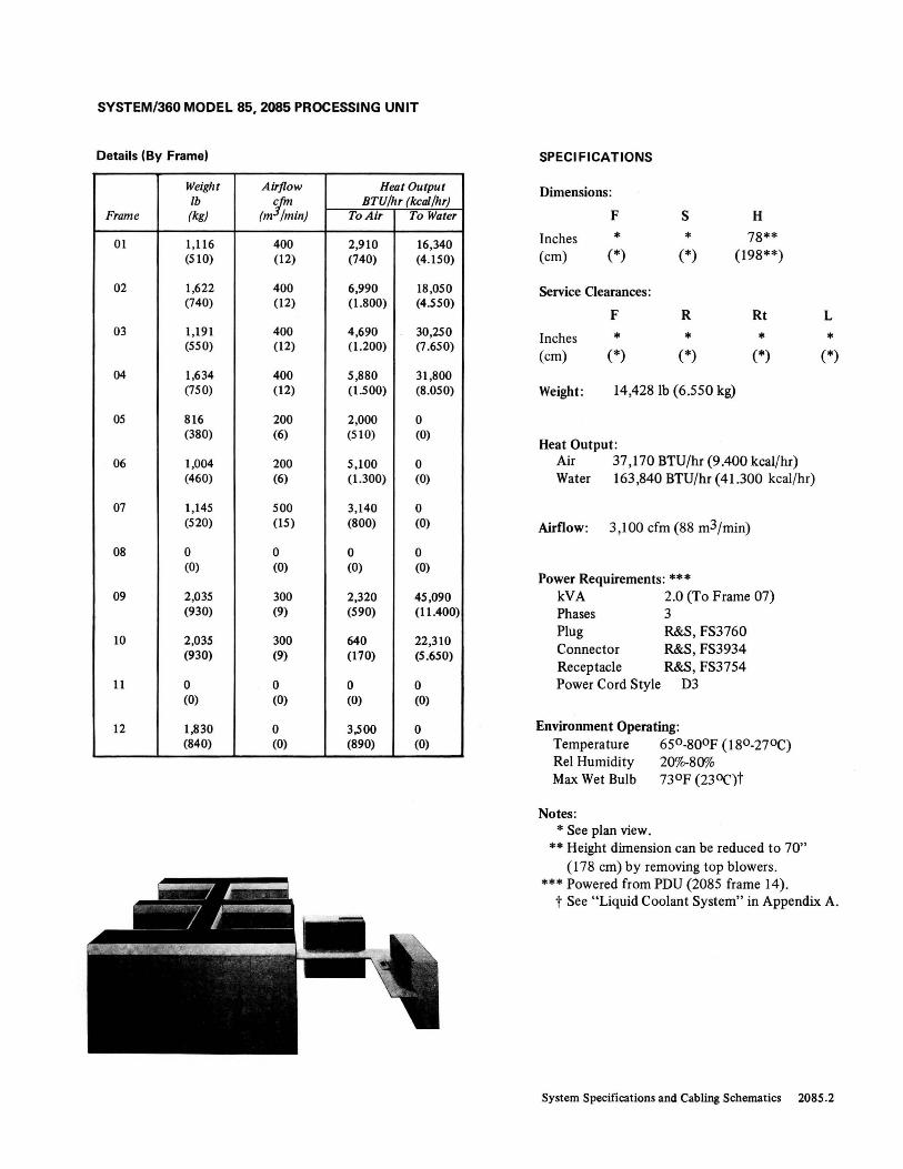
SYSTEM/360 MODEL 85,2085 PROCESSING UNIT
Details (By Frame)
Weight Airflow Hellt Output Ib
(m1;;in) BTU/hr (kcal/hr)
Frame (kg) To Air To Water
01 1,116 400 2,910 16,340 (510) (12) (740) (4.150)
02 1,622 400 6,990 18,050 (740) (12) (1.800) (4.550)
03 1,191 400 4,690 30,250 (550) (12) (1.200) (7.650)
04 1,634 400 5,880 31,800 (750) (12) (1.500) (8.050)
05 816 200 2,000 0 (380) (6) (510) (0)
06 1,004 200 5,100 0 (460) (6) (1.300) (0)
07 1,145 500 3,140 0 (520) (15) (800) (0)
08 0 0 0 0 (0) (0) (0) (0)
09 2,035 300 2,320 45 ,090 (930) (9) (590) (11.400)
10 2,035 300 640 22,310 (930) (9) (170) (5.650)
11 0 0 0 0 (0) (0) (0) (0)
12 1,830 0 3,500 0 (840) (0) (890) (0)
SPECIFICATIONS
Dimensions:
F S H
Inches * * 78** (cm) (*) (*) (198**)
Service Clearances:
F R Rt
Inches * * * (cm) (*) (*) (*)
Weight: 14,428 lb (6.550 kg)
Heat Output: Air 37,170 BTU/hr (9.400 kcal/hr) Water 163,840 BTU/hr (41.300 kcal/hr)
Airflow: 3,100 cfm (88 m3/min)
Power Requirements: *** kV A 2.0 (To Frame 07) Phases 3 Plug R&S, FS3760 Connector R&S, FS3934 Receptacle R&s, FS3754 Power Cord Style D3
Environment Operating: Temperature 650-800F (180-270C) Rei Humidity 20%-80% Max Wet Bulb 73°F (23 0C)t
Notes: * See plan view.
** Height dimension can be reduced to 70" (178 cm) by removing top blowers.
*** Powered from PDU (2085 frame 14).
L
* (*)
t See "Liquid Coolant System" in Appendix A.
System Specifications and Cabling Schematics 2085.2

SYSTEM/360 MODEL 85, POWER DISTRIBUTION UNIT (PDU)-2085 FRAME 14
PLAN VIEW
,- - - -e- - - - -0-- - -li I I· (8 Places) I ,-- r 3-1/2" I I 30" I 36" ~ (4 Places) b I I
~u u~ I + @ T t 2" ~ 2~ ~
I 21" x 35" l8J 5-1/2": I (4 Places) .I.
<I> L (j)
I 8" i; + I I I ~ I
t
I L----e
L30" '
415/441
CE 2" (4 Places)
I /
60"
EI
/
I I I I (I I " I I I
To Generator : \: :::
-_4~ ~ -=--=~ 415/441 Hz I \ \ /' I \ \ ;' ~r Flexible
I \ / Conduit ~_ ,/ /1 1-.L_~5~/dJ Hzl o-~ ~ 150
Left Side
Notes:
Junction Boxes:
1--50/60 Hz 1--415/441 Hz
-1-. Flexible conduits to P, Q, and Rare 3 inches (8 em). 2. Flexible conduit to S is I inch (3 em).
Front
3. Pigtail cable is provided from each conduit location (8-foot I 244-cml length from exit). 4. Flexible condu it and junction boxes are provided by the customer. 5. Clamp fittings for flexible conduit are provided.
Entry
No. of P Q R 5 Wires
6--#2/0 6--#2/0 6--# I/O 3--#10 and Size (AWG) 1-3 6 1--#6 1--#6 2--#12
Junction Box Connection Details
SPECI F ICAT IONS
Dimensions:
F S H
Inches 30 60 70 (cm) (76) (152) (178)
Service Clearances:
F R Rt
Inches 36 36 30 (cm) (91) (91) (76)
Weight: 1,500 lb (690 kg)
Heat Output: Negligible
Airflow: o cfm (0 m3/min)
Power Requirements (kV A):
50/60 Hz 415/441 Hz
I 14.5 81.0
Models J,
18.0 87.0
K , 27.0 105.0
L
30 (76)
L 36.0
132.0
System Specifications and Cabling Schematics 2085.3

MOTOR-:.GENERATOR STARTER (REMOTE)
FOR SYSTEM/360 MODEL 85 (50-HZ INPUT)
PLAN VIEW
,-0-- - -0-- - -0- r-T , 'I I
<:> 37-1/2,,-1 30"
f ?~ , 'i 30"
A 18" (2 Places)
1-1. 30"
9 Front 9 t L -0-- - -0-- - -0- ...J __ --L.t
2085.4 Installation-Manual-Physical-:Planning
SPECI FICATIONS
Dimensions:
F S H
408V Inches 37-1/2 30 90 (cm) (95) (76) (229)
Service Clearances:
F R Rt
Inches 30 30 0 (cm) (76) (76) (0)
Weight:
NEMA Size #6: 220,380, and 408V 2,0001b (910 kg)
Power Requirements:
Motor starter can be set at one of the following:
Starting Cu"ent Starting Tap 220 V 380 V 408 V Time Setting (A) (A) (A) (sec) (percent)
. 3,110 1,800 1,950 7.0 100 1,980 1,190 1,245 9.5 80
- 1,304 760 822 14.5 65
L
0 (0)
(factory setting) 77(, 450 487 25.0 50

MOTOR·GENERATOR STARTER (REMOTE) FOR SYSTEM/360 MODEL 85 (60·HZ INPUT)
PLAN VIEW
Detachable Rear Panel
,-0 -B--G--il <;> 37-1/2"~
:-1" ---- - - ------- --- ------ ----. X See specifications at right
A 30"
9L
Front ~ t ~ - -0-- - -€)-l-----'--
SPECIFICATIONS
Dimensions:
F S H
~08/230V Inches 37-1/2 30 90 (em) (95) (76) (229)
440V Inches 37,.1/2 20 80 (em) (95) (51) (203)
Service Clearances:
F R Rt L
Inches 30 30 0 0 (em) (76) (76) (0) (0)
Weight: NEMA Size #6: 208/230V
2,0001b (910 kg) NEMA Size #5: 440V
8001b (370 kg)
Power Requirements:
Motor starter can be set at one of the following:
Starting Current Starting Time Tap
208/230 V 440V (Approximate) Setting
(A) (A) (sec) (percent)
2,760 1,460 7 100
1,760 935 10 80
1,160 615 15 65 (factory setting)
690 365 25 50
System Specifications and Cabling Schematics 2085.5

MOTOR GENERATOR (REMOTE) FOR SYSTEM!360 MODEL 85 (50-HZ INPUT)
PLAN VIEW
Location of Vibration Mounts (3) r- -0- ---"- - - <>- ---:,~ --<>- - --0---~~Cl
I 30" I ~30" 70" --I I
t 30V --'-~" ! t ¢ 26-1/2" --r.~i--L- ~8" 9 I (2 Places) , \ I ! 34" I
~ I ~ I , ' I I I I I" ~6-1/4" f.-29- 1/4"T-----l Drill 7/16" Diameter I ]. 3
10 (2 Places) 'T I Mounting Holes (6) .l
Y 13-1/8" 48-7/8"--1 (If Desired) Y I (2 Places) Front (2 Places) I L_ -0- -- --(r- ----o------o-----o----~ ----o---J
2085.6 Installation Manual-Physical Planning
SPECI flCATIONS
Dimensions:
F S H
Inches 100 34 53 (cm) (254) (86) (135)
Service Clearances:
F R Rt L
Inches 30 30 30 30 (cm) (76) (76) (76) (76)
Weight: 4,630 lb (2.100 kg)
Heat Output (Max): 102,000 BTU/hr (25.750 kcal/hr)
Power Requirements:
Input: Induction Motor-225 hp, 380/408V, 50 Hz, 284/305A full load, code F, 400 C maximum ambient, dripproof enclosure
Output: Synchronous Generator-175 kVA, 208V, 3 phase, 441 Hz, 485A full load, 700 C temperature rise, dripproof enclosure
Notes: The installation and maintenance of the motor-generator (including starter) unit will be the responsibility of the customer.
At time of installation: 1. An overvoltage circuit is provided in the motor
generator regulator. This must be adjusted to remove generator output when the 441-Hz line voltage reaches 220 ± 2V (rms).
2. The generator output voltage must be set so that the voltage measured by the meter located on the power distribution unit (2085 frame 14) reads between the center and upper scribe marks.
3. Consult motor-generator manufacturer's instruction manual for further installation procedures and maintenance.
Customer to supply the following wiring: 1. Input feeders to the motor. 2. Wiring between motor-generator unit and motor starter. 3. Output feeders from generator to PDU (frame 14); if
in conduit, this must be a nonferrous conduit. Maximum voltage drop at the PDU should not exceed 5%.
4. Five remote leads required from generator to PDU: three leads for sensing (2-ohm maximum resistance) and two leads for indicator lights.
5. The EPO pushbutton in computer room must remotely cut off power to the motor and output of the generator. Shunt trips are provided for this purpose in both circuit breakers.

MOTOR GENERATOR (REMOTE) FOR SYSTEM/360 MODEL 85 (60-HZ INPUT)
PLAN VIEW
Location of Vibration Mounts (3) ,- -€)- - - --e---
t ---t>- - - ---0- - - TO-l
'------1---- 86" 30" t f---30"-....... t-------,1--- 70" -----.1
I I I ~ 30-1/8"
:r=J f I 13-1/8"
L~~c~ __
6-1/4" I.- 29-1/4" (2 Places)
48-7/8" (If Desired) ~
e- _ (2 Pla~ ~ro~ _ -e- __ -(7- J
SPECI F ICATIONS
Dimensions:
F S H
Inches 86 34 53 (cm) (218) (86) (135)
Service Clearances:
F R Rt L
Inches 30 30 30 30 (cm) (76) (76) (76) (76)
Weight: 4,2001b (1.950 kg)
Heat Output (Max): 208/230V: 86,000 BTU/hr (21.700 kcal/hr) 440V: 102,000 BTU/hr (25.750 kcal/hr)
Power Requirements: Input:
Induction Motor-200 hp, 208/230V or 440V, 60 Hz, 240A full load, NEMA design B, code F, 400 C maximum ambient, dripproof enclosure
Output: Synchronous Generator-175kV A, 208V, 3 phase, 415 Hz, 485A full load, 700 C temperature rise, dripproof enclosure
Notes: The installation and maintenance of the motor-generator (including starter) unit will be the responsibility of the customer.
At time of installation: 1. An overvoltage circuit is provided in the motor
generator regulator. This must be adjusted to remove generator output when the 415-Hz line voltage reaches 220 ± 2V (rms).
2. The generator output voltage must be set so that the voltage measured by the meter located on the power distribution unit (2085 frame 14) reads between the center and upper scribe marks.
3. Consult motor-generator manufacturer's instruction manual for further installation procedures and maintenance.
Customer to supply the following wiring: 1. Input feeders to the motor. 2. Wiring between motor-generator unit and motor starter. 3. Output feeders from generator to PDU (frame 14); if
in conduit, this must be a nonferrous conduit. Maximum voltage drop at the PDU should not exceed 5%.
4. Five remote leads required from generator to PDU: three leads for sensing (2-ohm maximum resistance) and two leads for indicator lights.
5. The EPO pushbutton in computer room must remotely cut off power to the motor and output of the generator. Shunt trips are provided for this purpose in both circuit breakers.
System Specifications and Cabling Schematics 2085.7

SYSTEM/360 MODEL 85 CABLING SCHEMATIC
2085 ~====~-~-==--~~ -=-_ ~=-=- ---=-=-_ __-~-== ==~ - ~ il-----l @ =- - - - - -~--I I I I I I
(PDU) ==--=--=--=---=--=---=---=--=--=---=--=--=---::::.-:::: ==--Ill I " I I I , ( '1!85-19! I JJJ.-85-14 85-52 85-15 I II' " I I I '
, 185-20~+i- - - - - -+ CERoom 'fI, I I I I I 85-16tH] I III I I I I, I I ,
II II I II I I I I I I II II I,'" I' 85-22 I I 85-25 ,
1/ I', ' I , " {or 85-41)-H I (or 85-42)--..1
I 85-09 I " ,I I I 85-36 I II, II L----------------l II', I 85-15" L.: 85-21 ~ I ~ 85-21 I 1,1
11
, ~-==-r--=--===--=--=-_l-l I III %, 85-12 I i(a85-40) I I I (0.85-40) I,
II (~8585~3) 1.}85-14 II r I (a 85-39) I I I I I I rl ,II ~ ,I 1'1 I
III @> @ II III I I I I I I I III , ' III I I' I I I 1'1. @ @ @ @ I I 11,1 ,I I @) I ' ,I' , I II 'I , , 'L---1 2085 fn;\01 I ~~-II,' I ,
" ~ ,Note 10 ,85-38) , ,
" I , 85-10 V I I I , 85-24 I @ 2385 I
185~ I I IQ6\ -====_ 85-IJ f!-II 'I ,
I )I' 'e/ I 85-38) -' , , 85-37 V ,C @) @) @
I " l 85-11 , "I I II
I I , (or , , 1 85- 38) @
I 1,1 , ~ I , I III , I I I 'I I 85-15 I I I I I I L~~IJ<>!..~-~U I I , I r, ~ ______________ ~=_-~-~~~~o~-_=_J ____ J I I I I , 2~f> 2~~0 2~~0 ,
I I , y-;:~~ y-;:~x ,
OuVi=E OuVi=E , ,
Legend:
-- Signal Cables - - - - Power Cables C Coupler (Note II) OCP Operator Control Panel
I OO-ClOI'-.OO-COl'-. I MNNN MNNN
I I I I I I I I lO lO lO lO lO lO lO lO
L_co~co",: ~co~co __ 85-08 __ -1
2085.8 Installation Manual-Physical Planning

SYSTEM/360 MODEL 85 CABLING SCHEMATIC
Group No. of Frame No. Cables From No.
85-01 13 2860 01 85-02 1 2860 85-03 1 2860 85-04 13 2860 # 2 02 85-05 1 2870 #1 85-06 13 2870 #1 85-07 13 2870 #1 85-08 1 2870 #1 85-09 14 Coupler 85-10 1 Coupler 85-11 (or 85-38) 1 2365-5 85-12 (or 85-39) 1 2365-5 85-13 6 2085 06 85-14 4 2085 85-15 3 2365-5 85-16 1 2085 07 85-17 1 System/360 CPU 85-18 2 Non-IBM 85-19 1 2085 14 85-20 1 2085 14 85-21 (or 85-40) 2 2385 85-22 (or 85-41) 1 2385 01 85-23 1 2085 06 85-24 1 2085 06 85-25 (or 85-42) 5 2385 11 85-26 24 Coupler 85-27 2 2860 85-28 2 2860 85-29 2 2860 85-30 2 2860 85-31 (or 85-43) 2 2085 12 85-32 2 2085 05 85-33 2 2085 05 85-34 2 2085 05 85-35 2 2085 05 85-36 1 2385 11 85-37 1 2385 11 85-44 1 Coupler 85-45 13 2870#2 85-52 1 2085 14
Notes: 1. One per channel unit (power control). 2. One per channel. 3. The sum of groups 85-01 plus 85-04 plus 85-06 plus 85-45
should not exceed 65 feet. 4. Required for 2870 when no 2860s are present. 5. To direct control (SF #3274). 6. To SF #3621, two-system EPO connection. 7. For SF #3622, multisystem EPO connection. See Note 2 in
"System/360 Specification Summary." 8. For channel-to-channel adapter (SF #1850). 9. Total cable length of 200 feet (unless modified by general
control-to-channel cabling schematic) available to attach up to seven control units.
10. Cable from 2365 or 2385 is fixed length and is shipped with storage unit. Cable couplers may be located within 6 feet radius of cable exit (6 feet includes height of floor).
Frame Max To No. Length (ft) Notes
2085 07 25 3 2085 07 45 2,15 2085 14 100 1 2860 #1 20 3 2085 07 65 15 2860#2 20 3 2085 07 25 4 2085 14 100 1 2085 08 30 11,18 2085 08 11,13 2365-5 20 12,20 2085 14 80 12,20 2085 14 75 2085 14 100 2085 14 80 2085 14 100 2085 05 100 5 2085 05 50 5 System/360 CPU 100 6 System/360 CPU 100 7 2085 14 100 20 2085 14 100 20 2085 09 50 2085 10 50 2085 14 100 20 2085 08 30 11 Multiplexer Channel 8,9 Selector Channel 8,9 Control Unit 8,9 Channel-to-Channel Adapter 8,9 2085 14 12,20 Selector Channel 9, 16 Multiplexer Channel 9, 16 Control Unit 9, 16 Channel-to-Channel Adapter 8,9,16 2085 14 100 2085 06 100 2085 08 30 11,17 2870#1 20 3 CE Room 100 19
11. Three couplers each for 2365; five for 2385. See "System/360 Model 85 Cabling Schematic (2880 Attachment)" for size. Couplers should be accessible.
12. Sequence and control (EPO). 13. Required only on 2365 #3 and #4 (J configuration). Cable
length must equal 85-09 plus 9 feet. 14. Fixed-length cable (4 feet) is shipped with machine. 15. Maximum "X" length:
25 feet for one channel frame 45 feet for two channel frames 65 feet for three or four channel frames.
16. For operator console feature (SF #5450). 17. Required for 2385 Model 2 only. . 18. The "X" dimension for both 85-09 groups must be the same. 19. From BSM analyzer located in CE room (CER). 20. For 50-Hz machines, use group number in parentheses.
System Specifications and Cabling Schematics 2085.9

SYSTEM/360 MODEL 85 CABLING SCHEMATIC (2880 ATTACHMENT)
,-r-=-= =- 2085
I I rr-_- @ I I : I r - L......-_(_PD_U~)_~ t ~ I I I I I I t I , I : I 1+1,
I I IT! 2880 2880 2880 2880 2880 2880: I I I I T #6 #5 #4 #3 . #2 # J I I I , I :
I I I I I I I I' I I I I I ,
\ \ \ \ \ &5-50 J I I I , I \ \ \ \ 85-50 ~~O ____ - _ --=---=- --.J I I
\ \ ,&5-50 ~ - - -- - - - - - - - - - - --.J..J ' I
~~O ____ ~~~--= = =--=--=--===- =--= =: =-=---=-= = -= -= == ~ -=-~ =:=-=-~--=-= -=~J 85-46 85-46 85-46 85-46 85-46 85-46
2870 2870 2860 2860
2085
@)
See "System/360 Model 85 Cabling Schematic" for 2860 and 2870 cabl i ng . C Coupler (See accompanying
photograph) Power Cables - - - -Signal Cables
Group No. of No. Cables From
8546 9 2880 8547 8 Coupler 8548 8 Coupler 85-49 Coupler 85-50 2880 85-51 Coupler
Notes:
To
Coupler Coupler 2085 2085 2085 Coupler
Frame No.
08 08 14
Max Length (ft)
250
1. Cable length must be a minimum of 10 feet (C-T-C). All cables, except 85-50, are ordered connector-to-connector (C-T -C); that is, when a 1O-foot cable is ordered, the order department will send a cable with a total length of 10 feet from connector to connector.
2. Cable dimensi - .~ and number of couplers, for each 2880, must satisfy both the following equations: a. Maximum .enuation equation (based on circuit performance characteristics):
1.5(Xl) + X2 + 35(N-l) ~ 287
b. Maximum delay equation (based on system data rate performance characteristics):
Xl +X2~105
2085.10 Installation Manual-Physical Planning
Notes
1,2,5 2 1,2,5 2,3
4

SYSTEM/360 MODEL 85 CABLING SCHEMATIC (2880 ATTACHMENT)
Where:
Xl the C-T-C length (in feet) of cable group 85-46 between the 2880 and its, associated coupler.
X2 the C-T -C length (in feet) of the sum of all intervening cable groups 85-47 and 85-48 between the 2880's associated coupler and the 2085.
N = the number of couplers between the 2880 and the 2085.
See Examples 1 and 2.
l'
X1(1)
Example 1:
85-46
85-49
85-48 ---+-~
Coupler #1
Assume X2(1) = 10 feet (C-T-C):
Find maximum length (C-T -C) of X1(1)- Note 5 may apply.
Note 2, equation a: 1.5 (Xl) + X2 + 35(N-1) = 287 1.5 (Xl) = 287 - 10
Note 2, equation b:
Xl = 277 = 184 feet (C-T-C) 1.5
Xl + X2 = 105 Xl = 105 - 10 = 95 feet (C-T-C)
2085
Maximum length to satisfy both equations is 95 feet (C-T-C) from equation b. However, in those cases specified in note 5, it would be furtner restricted to 10 feet (C-T-C) when those special control units were attached to the 2880.
The floor-to-connector distance in the 2880 is 7 feet and in the 2085 it is 2 feet. For planning purposes in Example 1, the maximum "X" distance for group 85-46 (X1(1)) is 95 feet - 7 feet = 88 feet and for group 85-48 (X2(1)) is 10 feet - 2 feet = 8 feet.
System Specifications and Cabling Schematics 2085.11

SYSTEM/360 MODEL 85 CABLING SCHEMATIC (2880 ATTACHMENT)
85-47 85-47 85-47 85-47 85-47
C #5 C #4 C #3 C #2 C #1 .. C 85-48 ... ... ... ... .--. #6
.. #5
~
#4 ,
#3 #2 ~
#1 ,.
X2(6) X2(5) X2(4) X2(3) X2(2) X2(1)
85-46#6 10 feet 10 feet 10 feet 10 feet 10 feet
X1(6) 85-46 #1
30 feet ,.1.- .... lJ ,..., ,.l,.I X1 (1)
"-- - - -~ ~
Other 2880s
2880 #6
hxample 2:
Assume X2(1), X2(2), X2(3), X2(4), and X2(5) all equal 10 feet (C-T-C); X 1(6) equals 30 feet (C-T-C).
Find maximum length (C-T-C) ofX2(6). Note 5 does not apply. -
Note 2, equation a: 1.5(X1) + X2 + 35(N-1) = 287 1.5(30) + X2 + 35(5) = 287
Note 2, equation b:
45 + X2 + 175 = 287 X2 = 287 - (45 + 175) = 67 X2(1) + X2(2) + X2(3) + X2(4) + X2(5) + X2(6) = 67 X2(6) = 67 - 50 = 17 feet (C-T-C)
Xl + X2 = 105 X2 = 105 - 30 = 75 X2(6) = 75 - 50 = 25 feet (C-T-C)
Maximum length to satisfy both equations is 17 feet (C-T -C) from equation a. For planning purposes in Example 2, group 8546 #6 (X9(6», the maximum "X" dimension is
30 feet - 7 feet = 23 feet. The maximum "X" dimension for group 8547 #5 is 17 feet because the C-T -C equals the "X" dimension for this group.
3. Cable C-T -C length of group 8549 must always equal the sum of the C-T -C lengths of intervening groups 8547 and 85-48 plus 6 additional feet for eac~ intervening coupler. This provides equal delay along the simplex path (8549) and the multiplex path (8547,8548, and couplers).
4. Length of group 85-51 must be equal to the length of the group 8547 cables between the couplers. 5. A 2835 Modell, 2835 Model 2, or a 2820 must be attached to the first 2880; the maximum length for
cable group 8546 is 10 feet (C-T -C) and the maximum length for cable group 8548 is 20 feet (C-T -C).
2085.12 Installation Manual-Physical Planning
30 feet
2880 #1
2085

SYSTEM/360 MODEL 85 CABLING SCHEMATIC (2880 ATTACHMENT)
Memory (Storoge) Bus Coupler (2365/ 2385)
System Specifications and Cabling Schematics 2085.13

Section 3. Machine Specifications and Cabling Schematics
1051 CONTROL UNIT MODELS 1 AND N1 SPECI FICATIONS
PLAN VIEW Dimensions :
F S H
Inches 26 15 27 (cm) (66) (38) (69)
Service Clearances:
F R Rt L
Inches 0 36 0 30 (cm) (0) (91) (0) (76)
Weight : 1951b (89 kg)
(4 Places) (4 Pi a,
Heat Output : 670 BTU/hr (170 kcal/hr)
Airflow: 0 cfm (0 m3/min)
Power Requirements: kVA 0.2 Phases 1 Plug R&S, FS3720 Connector R&S, FS3913 Receptacle R&S, FS3743 Power Cord Style AS
Environment Operating: Temperature 50°_110°F (10°-43°C) ReI Humidity 100/0-80% Max Wet Bulb 80°F (27°C)
Environment Nonoperating: Temperature 50°_110°F (lO°-43°C) ReI Humidity 100/0-80% Max Wet Bulb 80°F (27°C)
Cable Limitations: Fixed length to 2030.
Machine Specifications and Cabling Schematics 1051

SYSTEM/360 MODEL 195 J AND K-3195 PROCESSING UNIT AND STORAGE
PLAN VIEW (Not 1/4" = l' Scale)
I- -,-. -312"'--------1
1,.
(Mode~o~'Only;1 3-1/4" (Typical)
(""'I--_-_-_:.,_e-_,_.-__ -_~ -6- - - -:;" - - - T --.... __ ---&'--_(Mo_6:~,IKo~iy) - ~t
I I I
<\>
242-1/21' I
3-3/8". I
ft5==(2 P!=fe=S) ;---'1 t (F~~~I Only)<\>
. __ ---Li l t I
cp
219-1/4"
1 166-5/8" I 169-~" -t-~~~=~~-rr--
cp
I 1
165-1 4" 0 0 I
I " I cp 22-3/4" [7r48-1/2"----l17-1/2"~:-...... hn\
I 30".a.U • (2 Places) t-- ~ _ r,-., /. ... ,
1 I " ,/" I I
L I I " / I I I - - -e- - ----"l rll.J __ --.:\- L __ I_L1
2-1/2" I I • I (2 Places) " I I~II
• <P ~
1. The two_ction coven at the left of frame 19 and the associated main storage frames fold away from the machine to a fixed angle when unlatched. The folded sections can slide on a continuous track the length of the left edge of the referenced r-. The coven ot the right of frame 18 and the associated main storage frames work the same war on the right edge.
2. Enlarged opening 12" x 2"" (30 em x 61 em) is required for additional cables for the extended channels feature (SF 13851).
... ----------151-1/2"'-!·----------~:1·
• Typical dimensions on frames 50 and 51. • Typical dimensions on frames 18 and 19.
• Typical dimensions on frames 06, 08, and 10.
3195.1 Installation 'Manual-Physical Planning
t I
<P
Heat Exchanger Gate • (2 Places)
76-1/2"

SYSTEM/360 MODEL 195 J AND K-3195 PROCESSING UNIT AND STORAGE
Details (By Frame. Without Covers)
Dimensions Weight Airflow Heat Output FxSxH Ib efm BTU/hr (keal/hr)
Frame inches (em) (kg) (m3/min) loA" 10 Water
06 66 x 15 x 70 1,400 400 7,000 7,000 (168 x 38 x 178) (640) (12) (1.800) (1.800)
08 66 x 15 x 70 1,400 400 5,000 5,000 (168 x 38 x 178) (640) (12) (1.300) (1.300)
10 15 x 66 x 70 1,400 400 6,500 6,500 (38 x 168 x 178) (640) (12) (1.650) (1.650)
12 15 x 50 x 70 1,000 250 7,800 2,500 (38 x 127 x 178) (460) (8) (2.000) (640)
14 30 x 30 x 70 1,300 - - 21,000 (76 x 76 x 178) (590) (5.300)
15 50 x 30 x 70 1,000 300 3,000 -(127 x 76 x 178) (460) (9) (760)
16 15 x 30 x 70 650 150 2,000 -(38 x 76 x 178) (300) (5) (510)
18 46 x 30 x 70 1,800 - - -
(117 x 76 x 178) (820)
19 46 x 30 x 70 1,800 - - -(117 x 76 x 178) (820)
50 46 x 68* x 70 3,500* 2,800 25,000 20,000 (117 x 173* x 178) (1.600*) (80) (6.350) (5.050)
51 46 x 68* x 70 3,500* 2,800 25,000 20,000 (117 x 173* x 178) (1.600*) (80) (6.350) (5.050)
CPU Totals (By Model)
Weight Airflow Heat Output
Ib efm BTU/hr (keal/hr) Model (kg) (m3/min) 10 Air To Water Remarks
J 13,450 4,700 . 56,300 62,000 Omit frames (6.150) (140) (14.200) (15.650) 18 and 51
K 18,750 7,500 81,300 82,000 (8.550) (220) (20.500) (20.700)
SPECI FICATIONS
Dimensions:
F
Inches ** (em) (**)
Service Clearances:
F
Inches ** (em) (**)
Power Requirements:
S
** (**)
R
** (**)
H
70 (178)
Rt L
** ** (**) (**)
The Model 195 J and K receive 50/60-Hz and 415/441-Hz power from 3080 Models 1,2, and 3 and 3085 PDU.
Environment Operating: Temperature 65° -800 F ( 18°-27°C) Rel Humidity 200/0-80% Max Wet Bulb 75°F (240 C)***
Notes: * The 68 inches (173 cm) represents width of
two 34-inch (86-cm) wide subframes, each weighing 1,750 lb (800 kg).
** See plan view. *** See "Liquid Coolant System" in Appendix A.
System Specifications and Cabling Schematics 3195.2

SYSTEM/3GO MODEL 195 KJ AND L-3195 PROCESSING UNIT AND STORAGE
PLAN VIEW (Not 1/4" = l' Scale)
~----------------------312"--------~--------------_
289"
308-1/4"
I I II 1\ I II 13-1/4" I
---l\---t-P--. / " I I
76-1/2"
/ • " I --- 4" x 4" ...... _L ...J +--''''''-----1t----''-------t--..a..
(2 Places) j -e-----&
6-1/2" 5-3/4"
1. The two-section covers at the left of frame 19 and the associated main storage frames fold away fram the machine to a fixed ongle when unlatched. The folded sections can slide on a continuous track the length of the left edge of the referenced frames. The covers at the right of frame 18 and the associated main storage frames wort< the same way on the right edge.
• (2 Places) I 68-1/8" : •
..... ----------151-1/2"'------------t-·
2. Enlarged opening 12" x 24" (30 em x 61 em) Is required for additional cables for the extended channels feature (SF '3851).
• Typical dimensions on frames SO, 51, 52, and 53.
• Typical dimensions on frames 18 and 19.
• Typical dimensions on frames 06, 08, and 10.
3195.3 Installation Manual-Physical Planning
Heat Exchanger Gate • (2 Places)
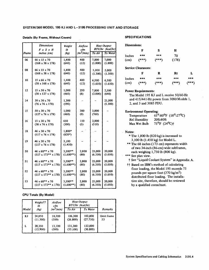
SYSTEM/360 MODEL 195 KJ AND L-3195 PROCESSING UNIT AND STORAGE
Details (By Frame, Without Covers)
Dimensions Weight Airflow Heat Output
FxSxH Ib efm BTU/hr (keal/hr)
Frame inches (em) (kg) (m3/min) To Air To Water·
06 66 x 15 x 70 1,400 400 7,000 7,000 (168 x 38 x 178) (640) (12) (1.800) (1.800)
08 66 x 15 x 70 1,400 400 5,000 5,000 (168 x 38 x 178) (640) (12) (1.300) (1.300)
10 15 x 66 x 70 1,400 400 6,500 6,500 (38 x 168 x 178) (640) (12) (1.650) (1.650)
12 15 x 50 x 70 1,000 250 7,800 2,500 (38 x 127 x 178) (460) (8) (2.000) (640)
14 30 x 30 x 70 1,300 - - 21,000 (76 X 76 x 178) (590) (5.300)
15 50 x 30 x 70 1,000 300 3,000 -(127 x 76 x 178) (460) (9) (760)
16 15 x 30 x 70 650 150 2,000 -(38 x 76 x 178) (300) (5) (510)
18 46 x 30 x 70 1,800* - - -(117 x 76 x 178) (820*)
19 46 x 30 x 70 3,100 - - -(117 x 76 x 178) (1.450)
50 46 x68** x 70 3,500** 2,800 25,000 20,000 (117 x 173** x 178) (1.600**) (80) (6.350) (5.050)
51 46 x68** x 70 3,500** 2,800 25,000 20,000 (117 x 173** x 178) (1.600**) (80) (6.350) (5.050)
52 46 x 68** x 70 3,500** 2,800 25,000 20,000 (117 x 173** x 178) ~1.600**) (80) (6.350) (5.050)
53 46 x 68** x 70 3,500** 2,800 25,000 20,000 (117 x 173** x 178) (1.600**) (80) (6.350) (5.050)
CPU Totals (By Model)
Weightft Airflow Heat Output
Ib efm BTU/hr (keal/hr)
Model (kg) (m3/min) To Air To Water Remarks
KJ 24,850 10,300 106,300 102,000 Omit frame (11.300) (300) (26.800) (27.750) 53
L 28,350 13,100 131,300 122,000 (12.900) (380) (33.100) (30.800)
SPECI FICATIONS
Dimensions:
F S H
Inches *** *** 70 (cm) (***) (***) (178)
Service Clearances:
F R Rt L
Inches *** *** *** *** (cm) (***) (***) (***) (***)
Power Requirements: The Model 195 KJ and L receive SO/6000Hz and 415/441-Hz power from 3080 Models 1, 2, and 3 and 3085 PDU.
Environment Operating: Temperature 65°-800 F (180 -270 C) Rei Humidity 20% .. 80% Max Wet Bulb 75°F (240 C)t
Notes: * The 1,800 lb (820 kg) is increased to
3,1001b (1.450 kg) for Model L. ** The 68 inches (173 cm) represents width
of two 34-inch (86-cm) wide subframes, each weighing 1,750 lb (800 kg).
*** See plan view. t See "Liquid Coolant System" in Appendix A.
tt Based on IBM's method of calculating floor loading, the Model 195 exceeds 75 pounds per square foot (370 kg/m2) distribu ted floor loading. The installation site, therefore, should be reviewed by a qualified consultant.
System Specifications and Cabling Schematics 3195.4

MOTOR GENERATOR (REMOTE) FOR SYSTEM/360 MODEL 195 (50-HZ INPUT)
PLAN VIEW
3195.5 Installation Manual-Physical Flanning
Distribution Guide for Motor-Generator Output to 3085 PDU
Information in this guide accommodates a 208A full-load rating. Note that the conduit quantity column refers to the number of conduits recommended, each conduit containing all three phases in the wire size shown (three conductors per conduit) plus one AWG #2 insulated copper conductor in one of the conduits (the larger, if used) for ground. It is important that local and national wiring codes be followed.
Conduit Maximum Run Lengths by
Conduit T ype--ft (meters t)
Copper Size 3195 Wire Size Quantity (inches) Model Ferrous Nonferrous Nonmetallictt
250 MCM* I' 3 L 105** 130** 155*** (32**) (40**) (47***)
KJ 130** 155** 180*** (40**) (47**) (55***)
K 145** 170** 195*** (44**) (52**) (59***)
J 160** 185** 210*** (49**) (59**) (64***)
2/0 AWG 2 2 L 190 230 265 (58) (70) (8T)
KJ 230 270 305 (70) (82) (93)
K 255 295 330 (78) (90) (lOT)
J 280 320 355 (85) (98) (108)
250 MCM { ~ 2-~/2 } L 210 200 310 (64) (79) (94)
KJ 250 300 350 (76) (9T) (107)
K 275 325 375 (84) (99) (114)
I
J 300 350 400 (91) (107) (122)
* Single runs with conductors smaller than 250 MCM should not be used. MCM = thousand circular mils, where a circular mil is the cross-sectional area of a 0.001" (0,0254 mm) diameter wire (7.854(10)-7in 2 or 5,067(10)-4 mm 2).
** 9QoC insulation required. ***750 C insulation required.
tLengths ore rounded to the nearest unit.meter. ttOr cabled in air, where codes allow.

MOTOR GENERATOR (REMOTE) FOR SYSTEM/360 MODEL 195 (50-HZ INPUT)
SPECIFICATIONS
Dimensions:
F S H
Inches 81 36 51 (em) (206) (91) (130)
Service Clearances:
F R Rt L
Inches 30 30 30 30 (em) (76) (76) (76) (76)
Weight: 3,600 Ib* (1.650 kg*)
Heat Output (Approximate): 55,250 BTU/hr (14.000 kcal/hr)
Power Requirements: Phases 3
Input: Induction Motor-IOO hp, type K, class B, 220/240V or 380/408V, 50 ± 0.5 Hz
Locked Rotor Full Load Input (V) Current (A) Current (A)
220 Special start winding. 245
240 Less than 200% of full load. 230
380 142
408 134
Output: Synchronous Generator-75 kVA, 208V ± 2%, 441 Hz ± 6%
Notes: * Starter circuitry is included in the generator.
The installation and maintenance of the motor-generator (including starter) unit will be the responsibility of the customer. Consult motor-generator manufacturer's instruction manual for further installation procedures and maintenance.
Customer to supply the following wiring: 1. Input feeders to the motor. 2. Output feeders from generator to PDU junction box.
Maximum voltage drop at the PDU should not exceed 5%.
3. Five remote leads required from generator to PDU junctiqn box: three A WG # 14 leads for sensing and
two AWG #16 leads for indicator lights. 4. The EPO pushbutton in the computer room must re
motely cut off power to motor and output of the generator. Shunt trips are provided for this 'purpose in both circuit breakers.
System Specifications and Cabling Schematics 3195.6

MOTOR GENERATOR (REMOTE) FOR SYSTEM/360 MODEL 195 (60-HZ INPUT)
PLAN VIEW
3195.7 Installation Manual-Physical Planning
Distribution Guide for Motor-Generator Output to
3085 PDU
Information in this guide accommodates a 208A full-load rating. Note that the conduit quantity column refers to the number of conduits recommended, each conduit containing all three phases in the wire size shown (three conductors per conduit) plus one A WG #2 insulated copper conductor in one of the conduits (the larger, if used) for ground. It is important that local and national wiring codes be followed.
Conduit Maximum Run Lengths by
Conduit Type--ft (meterst)
Copper Size 3195 Wire Size Quantity (inches) Model Ferrous Nonferrous Nonmetallictt
250 MCM* 1 3 L 105** 130** 155*** (32**) (40**) (47***)
KJ 130** 155** 180*** (40**) (47**) (55***)
K 145** 170** 195*** (44**) (52**) (59***)
J 160** 185** 210*** (49**) (59**) (64***)
2/0 AWG 2 2 L 190 230 265 (58) (70) (81)
KJ 230 270 305 (70) (82) (93)
K 255 295 330 (78) (90) (101)
J 280 320 355 (85) (98) (108)
250 MCM { ~ 2-~/2} L 210 260 310 (64) (79) (94)
KJ 250 300 350 (76) (91) (107)
K 275 325 375 (84) (99) (114)
J 300 350 400 (91) (107) (122)
*Single runs with conductors smaller than 250 MCM should not be used. MCM = thousond circular mils, where a circular mil is the cross-sectional area of a 0.001" (0,0254 mm) diameter wire (7.854~10)-7in2 ar 5,067(10)-4 mm2).
** 900 C insulation required. *** 75 0 C insulation required.
t Lengths are rounded to the nearest unit meter. frO r cabled' in air, where codes allow.

MOTOR GENERATOR (REMOTE) FOR SYSTEM/360 MODEL 195 (60-HZ INPUT)
SPECIFICATIONS
Dimensions:
F S H
Inches 76 37 54 (cm) (193) (94) (137)
Service Clearances:
F R Rt L
Inches 30 30 30 30 (cm) (76) (76) (76) (76)
Weight: 3,0001b (1.400 kg)
Heat Output (Approximate): 40,000 BTU/hr (10.100 kcal/hr)
Power Requirements: * Phases 3 Input:
Induction Motor-90 hp, type K, NEMA design A, 208/230V or 440V ± 10%, 60 Hz ± 5%, 40°C maximum ambient
Starting Inrush Current: 208V-460A 230V-424A 440V-200A
Running Current at Full Load: 208V-235A 230V-212A 440V-I06A
Output: Synchronous Generator-75 kV A, 208V ± 2%, 415 Hz ± 6%
Notes: * Starter circuitry is included in the generator.
The installation and maintenance of the motor-generator (including starter) unit will be the responsibility of the customer. Consult motor-generator manufacturer's instruction manual for further installation procedures and maintenance.
Customer to supply the following wiring: 1. Input feeders to the motor. 2. Output feeders from generator to POU junction box.
Maximum voltage drop at the POU should not exceed 5%.
3. Five remote leads required from generator to POU junction box: three AWG #14 leads for sensing and two AWG #16 leads for indicator lights:
4. The EPO pushbutton in the computer room must remotely cut off power to motor and output of the generator. Shunt trips are provided for this purpose in both circuit breakers.
System Specifications and Cabling Schematics 3195.8

ROTARY CONVERTER (REMOTE) FOR SYSTEM/3GO MODEL 195 (WORLD TRADE ONLY)
PLAN VIEW SPECI FICATIONS
Dimensions:
F S
Inches 56 36 (cm) (142) (91)
Service Clearances:
F R
Inches 30 30 (cm) , (76) (76)
Weight: 1,5501b (710 kg)
H
37 (94)
Rt
30 (76)
L
30 (76)
Heat Output: 22,915 BTU/hr (5.800 kcal/hr)
Power Requirements: Phases 3 Input:
Induction Motor-50 hp, 220/240V or 380/408V, 50 Hz ± 0.5 Hz
Locked Rotor Full Load Input (V) Cu"ent (A) Cu"ent (A)
220 760 123 240 830 113 380 460 71 408 500 68
Output: Synchronous generator coupled to motor with timing belts, 208V, 60 Hz, 37.5 kVA
System Specifications and Cabling Schematics 3195.9
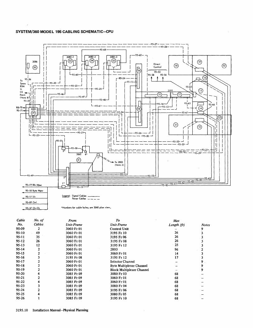
SYSTEM/3GO MODEL 195 CABLING SCHEMATIC-CPU
,---------------------95-27-------, /1----.------95-68-----------95-28---1 '
[:11 i r n@D ~ij ®] r ~@D~ r-:-l Dr"" ....----®-o --I-t--.;..l--®--,..----®-2--.
~ I I Iy 'Yi ~ __ J ® 1- ~::;' ''::~~, / / , L95-60-1- -1-- - -~ - - - - - '95-38 95-54 L-------!----=-==t~.,.___-----'
To 95!36 I / I I I 1 r- 95-24--- I t t t ~@ ~
Sp 1 r---+--95-20-..J I I I ,...95-11- 1 ~ ~ 'v ~ BS~e Llll_~..L ___ ~-95-23-J J r--- 95.1,5 ~ '"
in I r-T1--------- ,-95-25- I I 3195 C @ I'~ ~:om4-1111/1 I I .--95-46 I I ~®--=:J ~@--=:J "'-~~ - - 'I (Note 8d II 'I 95-47- _ r oJ ~ l ,
95-371 ,1, , I ' 95 48- I n i 95-16"--1' I 95~3 P ~-66' I 95-70 iilll -.J L-95-61------ ----d,J , r-95-13~ I L @ l,)- / 95-71+~ ~§ -~ ____________ J m®.' r ~ ___ ..J -I-<~ "I
-~ .~ ~ -9~4-::: i I 95-67-~~®1
II/Ili/L: --= ~--=-~-=---=----==--=-==~-, /, I I I ® /~v7 ~~ 'jl / / L__ ----------11' '-- II ./ ( r]8\ 1"- I' I L-----f-------- __ ~ , r "-:::.J
'L~-== 1--=-=---==-95-2~----1 I ,'L r --95-26-- J I I I I' I L-95-22--- 1---. , /' 'I L- ..... ----95-30--l I / II I
95~51 I. I /11 L'-- - 1------- 1--. ---95-33-....J J 1/ , , I" --1-1-------1------95-32- II I
95-50 IL __ r------I-I----------95-31- ..... JI I 3* L t.= - - - - - - - - - - - - - - - -95-52- - - - - - - :J
3060 4* r --- 1-------1----------95-29---1----'
5* ® 9S'1 L <---;~~~)
95-49 95-12 95-10-2* 95-45
95-41 95-42 95-43 95-44
95-19 Blk Mpxr 1 *
.J1. 95-40 95-15-
95-18 Byte Mpxr
95-17 Sir legend: Signal Cables ___ -- Power Cables ____
95-09 Ctrl
95-37 Ch-Ch *Numbers for coble holes; see 3060 plan view.
Cable No_ o[ From To Max No. Cables Unit-Frame Unit-Frame Length (It) Notes
95-09 2 3060 Fr 01 Control Unit 9 95-10 49 3060 Fr 01 3195 Fr 10 26 3 95-11 35 3060 Fr 01 3195Fr 06 26 3 95-12 26 3060 Fr 01 3195 Fr 08 26 3 95-13 12 3060 Fr 01 3195 Fr 12 25 3 95-14 2 3060 Fr 01 2803 96 2 95-15 2 3060 Fr 01 3060 Fr 01 14 3 95-16 3 3195 Fr 08 3195 Fr 12 17 3 95-17 2 3060 Fr 01 Selector Channel 9. 95-18 2 3060 Fr 01 Byte Multiplexer Channel 9 95-19 2 3060 Fr 01 Block MUltiplexer Channel 9 95-20 4 3085 Fr 09 3080 Fr 03 68 95-21 2 3085 Fr 09 3060 Fr 01 68 95-22 4 3085 Fr 09 3060 Fr 01 68 95-23 3 3085 Fr09 3080 Fr 04 68 95-24 2 3085 Fr 09 3195 Fr 06 68 95-25 4 3085 Fr 09 3080 Fr 05 68 95-26 3085 Fr 09 3195 Fr 10 68
3195.10 Installation Manual-Physical Planning

SYSTEM/360 MODEL 195 CABLING SCHEMATIC-CPU
Cable No. of From To Max No. Cables Unit-Frame Unit-Frame Length (ft)
95-27 3 3085 Fr 09 3195 Fr 19 68 95-28 3 3085 Fr 09 3195Fr19 68 95-29 4 3085 Fr 09 3195 Fr 16 68 95-30 1 3085 Fr 09 3195 Fr 12 68 95-31 3 3085 Fr 09 3195 Fr 14 68 95-32 3 3085 Fr 09 3195 Fr 18 68 95-33 3 3085 Fr 09 3195 Fr 18 68 95-34 2 3085 Fr 09 3195 Fr08 68 95-35 2 3085 Fr 09 CER (CE Room) 100 95-36 2 3085 Fr 09 3086 Fr 02 55 95-37 2 3060 Fr 01 Channel-to-Channel Adapter 95-38 2 Direct Control 3195 Fr 15 100 95-40 1 3060 Fr 01 3195 Fr 19 96 95-41 1 3060 Fr 01 3195 Fr 19 96 95-42 2 3060FrOI 3195 Fr 16 96 95-43 1 3060 Fr 01 3195 Fr 14 96 95-44 1 3060 Fr 01 3195 Fr 18 96 95-45 1 3060 Fr 01 3195 Fr 18 96 95-46 1 3060 Fr 01 3080 Fr 03 96 95-47 1 3060 Fr 01 3080 Fr 04 96 95-48 1 3060 Fr 01 3080 Fr 05 96 95-49 2 3085 Fr 09 3060 Fr 01 96 95-50 3 3060 Fr 01 3060 Fr 01 8 95-51 1 3060 Fr 01 3060 Fr 01 12 95-52 1 3085 Fr 09 3195Fr15 68 95-53 2 Direct Control 3195 Fr 15 100 95-54 2 Direct Control 3195Fr15 100 95-60 21 3080 Fr 03 3195 Fr06 24 95-61 22 3080 Fr 04 3195 Fr 08 24 95-62 21 3080 Fr 05 3195 Fr 10 24 95-63 19 3195 Fr 14 3195 Fr 12 10 95-65 3195 Fr 16 3195 Fr 15 8 95-66 3195 Fr 15 3195 Fr 14 8 95-67 3195 Fr 14 3195 Fr 06 24 95-68 3080 Fr 05 3080 Fr 04 68 95-70 3085 Fr 09 System/360 or System/370 CPU 100 95-71 3085 Fr 09 System/360 or System/370 CPU 100
Notes: 1. Direct control to other System/360 or System/370 CPUs (excluding 3195). 2. With more than one 2803 on a system, route to "last" 2803 (containingterminators). 3. Fixed-length cables. 4_ For 3195 Model L configuration only. 5_ For 3195 Model KJ and L configurations only. 6. For 3195 Model K, KJ, and L configurations only. 7. Cables in this group are divided between the two cutouts in the 3080. Measure from the 3195 cutout to the
farther 3080 cutout. 8. From BSM analyzer located in CE room (CER). 9. Total cable length of 200 feet (unless modified by general control-to-channel cabling schematic) available to attach
up to eight control units. 10. Direct control to non-IBM devices. 11. Direct control to another 3195. 12. To SF #3621, two-system EPO connection. 13. To SF #3622, multisystem EPO connection. See Note 2 in "System/360 Specification Summary."
Notes
5
4 6
8
9 10
5
6 4
3 3
11 1 7 7 7 3 3 3
12 13
System Specifications and Cabling Schematics 3195.11

SYSTEM/3GO MODEL 195 CABLING SCHEMATIC-CHANNELS
3195
@ J III I~ j~ I II' j~ t t 95-87, 95-88, or 95-89
Bus
-.... -.... -.... -..... Bus B and bus A cabling requirements are the same, except for groups 95-72 through 95-77. See listing and Note 6
, \ 95-75
95-76 or
95-77
B Bus A 95-87,95-88, or 95-89
95-87, 95-88, or 95-89
95-87, 95-88, or 95-89
95-72 95-73
or 95-74
It ~ 2860
~i7]: or
2880
~
95-90 95-91
or 95-92
Select Select one: one: 95-78 95-78
to to 95-86 95-86
I f r- 2860
_2§}.Q_ or or
2880 2880
~ ~
95-90 95-90 95-91 95-91
or or 95-92 95-92
~,------------------~~ 95-93 Channel-to-Channel Adapter 95-94 Multiplexer Channel 95-95 Block Multiplexer Channel 95-96 Selector Channel 95-97 Control Unit
3195.12 Installation Manual-Physical Planning
Select one: 95-78
to 95-86
J ~ 2860
.)i?:2: or
2880
To 3085 ~ (Fr09)
95-9 0 95-91
or 95-9 2
t
J
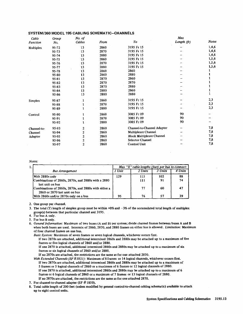
SYSTEM/360 MODEL 195 CABLING SCHEMATIC-CHANNELS Cable Group No. of Max
Function No. Cables From To Length (ft)
Multiplex 95-72 13 2860 3195 Fr 15 95-73 13 2870 3195 Fr 15 95-74 13 2880 3195 Fr 15 95-75 13 2860 3195 Fr 15 95-76 13 2870 3195 Fr 15 95-77 13 2880 3195 Fr 15 95-78 13 2860 2860 95-80 13 2860 2880 95-81 13 2870 2860 95-82 13 2870 2870 95-83 13 2870 2880 95-84 13 2880 2860 95-86 13 2880 2880
Simplex 95-87 2860 3195 Fr 15 95-88 2870 3195 Fr 15 95-89 2880 3195 Fr 15
Control 95-90 2860 3085 Fr 09 90 95-91 1 2870 3085 Fr 09 90 95-92 1 2880 3085 Fr 09 90
Channel-to- 95-93 2 2860 Channel-to-Channel Adapter
Channel 95-94 2 2860 MUltiplexer Channel Adapter 95-95 2 2860 Block Multiplexer Channel
95-96 2 2860 Selector Channel 95-97 2 2860 Control Unit
Notes:
1. Max "X" cable lengths (feet) per bus to connect: Bus A"angement 1 Unit 2 Units 3 Units 4 Units
With 2880s only 129 115 102 88 Combinations of 2860s, 2870s, and 2880s with a 2880 111 91 74
last unit on bus Combinations of 2860s, 2870s, and 2880s with either a 77 60 47
2860 or 2870 last unit on bus With 2860s and/or 2870s only on a bus 95 76 57 39
2. One group per channel. 3. The total (T) length of simplex group must be within +0% and - 3% of the accumulated total length of multiplex
group(s) between that particular channel and 3195. 4. For bus A only. 5. For bus B only. 6. General Information: Maximum of two buses (A and B) per system; divide channel frames between buses A and B
when both buses are used. Intermix of 2860, 2870, and 2880 frames on either bus is allowed. Limitation: Maximum of four channel frames on one bus. Basic System: Maximum of seven frames or seven logical channels, whichever occurs ftrst.
If two 2870s are attached, additional intermixed 2860s and 2880s may be attached up to a maximum of five frames or five logical channels of 2860 and/or 2880. If one 2870 is attached, additional intermixed 2860s and 2880s may be attached up to a maximum of six frames or six logical channels of 2860 and/or 2880. If no 2870s are attached, the restrictions are the same as for one attached 2870.
With Extended Channels (SF #3851): Maximum of 8 frames or 14 logical channels,whichever occurs first. If two 2870s are attached, additional intermixed 2860s and 2880s may be attached up to a maximum of 5 frames or 5 logical channels of 2860 or a maximum of 6 frames or 12 logical channels of 2880. If one 2870 is attached, additional intermixed 2860s and 2880s may be attached up to a maximum of 6 frames or 6 logical channels of 2860 or a maximum of 7 frames or 13 logical channels of 2880. If no 2870s are attached, the restrictions are the same as for one attached 2870.
7. For channel-to-channel adapter (SF # 1850). 8. Total cable length of 200 feet (unless modified by general control-to-channel cabling schematic) available to attach
up to eight control units.
Notes
1,4,6 1,4,6 1,4,6 1,5,6 1,5,6 1,5,6 1 1 1 1 1 1 1
2,3 2,3 2,3
7,8 7,8 7,8 7,8 7,8
System Specifications and Cabling Schematics 3195.13

SYSTEM/360 MODEL 195 CABLING SCHEMATIC-COOLANT HOSES
95-04~
v- 95-02
~ ~ Return
'~
¢ ¢ I I I I
95-03~ (0 I
10 !1 I @
I @ @ @~ ,I I I I I I I
9 ¢
~ @
H0--~ I~ ~ j.SL.
r-~
n @
'-~
I~ @ ~ ~ @ _~I I ,...-, I r ........ ' I
LT.J 3195 L- -.J
( p-95-01 (20 Hoses)
3086 Quick-connect Socket CDU {Typical}
¢ ~ 125 Feet ~
Connector to 8SM @ Connector Analyzer
S I / Quick-connect Plug tV ~ypicaO
(CE Room) 3080-1 3080-2 3080-3
3195.14 Installation Manual-Physical Planning

SYSTEM/360 MODEL 195 CABLING SCHEMATIC-COOLANT HOSES
Group No. of To 3195 No, Hoses From Frame Fixed Length (ft)
95-01 20 3086 See Schematic 95-02 2 3086 51 50 95-03 2 3086 52 50 95-04 2 3086 53 50
Notes: 1. Supply hoses have quick-connect plug fittings on end away from CDU and socket fittings on end going into CDU.
(Supply hoses only are shown on this schematic; assume one return hose for each supply hose.) Return hoses have quick-connect socket fittings on end away from CDU and plug fittings going into CDU. (Exceptions are BSM analyzer hoses, which have socket connectors on both ends of the supply and return hoses.)
2. Hoses are 50 feet (fixed length), except where otherwise noted. 3. Coolant hoses are ordered by group number only.
Specify: Group number 95-01 for Model J Group numbers 95-01 and 95-02 for Model K Group numbers 95-01, 95-02, and 95-03 for Model KJ Group numbers 95-01, 95-02, 95-03, and 95-04 for Model L.
Notes
1,2,3 1,3 1,3 1,3
System Specifications and Cabling Schem~tics 3195.15

1231 OPTICAL MARK PAGE READER MODEL N1
PLAN VIEW
-e-------<l-- ---e- - ---l'
I rn -l/2" I ~ 4 I 42 " I I I
t t I I I " I
G> 123 1-N I 24 " f I l 4 " x 4 " I + + I
I 13"S<i4" I f 4" (4 Places) r I (4 Places) 42 " I I ~m •
l-u H-'n ~B L-e-----o-----e-----<>- -.J
Note: For cabling information, see Section 4 , "Units w ith I ntegral or Abutted Controls."
1231 Installation Manual- Physical Planning
SPECI FICATIONS
Dimensions:
F S H
Inches 43-1/2 24 44-3/4 (em) (1lO) (61) (114)
Service Clearances:
F R Rt
Inches 42 42 30 (cm) (lO7) (lO7) (76)
Weight: 6201b (290 kg)
Heat Output : 3,700 BTU/hr (940 kcal/hr)
Airflow: 300 cfm (9 m3/min)
Power Requirements: kVA 1.2 Phases Plug Connector Receptacle Power Cord Style
1 R&S, FS3720 R&S, FS3913 R&S, FS3743
Al
Environment Operating: Temperature 50o-IlOoF (10°-43°C) ReI Humidity 8%-80%
Environment Nonoperating: Temperature 50°_110°F (10°-43°C) Rei Humidity 8%-80%
L
36 (91)
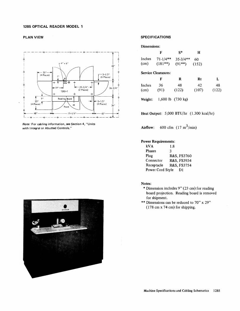
1285 OPTICAL READER MODEL 1
PLAN VIEW
,- - - - --<:>----0- ---0---- e-- ---<>----l-' I I
t t I 48" I I I ~ ~ I 3- 1/ 2" I (6 Places) I I + + I
t 1.-- 29- 1/4 ,, ---J -:J 26-3/ 4"t
I (2 Places) ~ I I + + I
~ t 9" RecxHngBoard ~ ~ I 23" 3- 1/2 " I I (4 Places) '-1 M (4 Places) 36" I I * : Front I t _~~8~ _ --<:> _ _ .~_e-__ ~1~: _ _ ~ _ __ -9-_4~_ -<>l j
Note: For cabling information, see Section 4, "Units
with Integral or Abutted Controls."
SPECI FICATIONS
Dimensions:
F S* H
Inches 71-1/4** 35-3/4** 60 (cm) (181**) (91 **) (152)
Service Clearances:
F R Rt L
Inches 36 48 42 48 (em) (91) (122) (107) (122)
Weight: 1,6001b (730 kg)
Heat Output: 5,000 BTU/hr (1.300 keal/hr)
Airflow: 600 cfm (17 m3 fmin)
Power Requirements: kVA 1.8 Phases 3 Plug R&S, FS3760 Connector R&S, FS3934 Receptacle R&S, FS3754 Power Cord Style Dl
Notes: * Dimension includes 9" (23 em) for reading
board projection. Reading board is removed for shipment.
** Dimensions can be reduced to 70" x 29" (178 em x 74 em) for shipping.
Machine Specifications and Cabling Schematics 1285

1404 PRINTER MODEL 2
PLAN VIEW
Note: For cabling information, see 2821 in IBM Systeml3!O Installation Manual-Physical Planning.
SPECI FICATIONS
Dimensions:
F S H
Inches 67-1/8* 31-3/4* 53-1/2* (em) (170*) (81 *) (136*)
Service Clearances:
F R Rt L
Inches 36 36 48 42 (em) (91) (91) (122) (107)
Weight : 1,600 Ib (730 kg)
Heat Output: 3,800 BTU/hr (960 keal/hr)
Airflow: 280 efm (8 m3/min)
Power Requirements: ** kVA 1.5
Notes:
* Front Forms Cart: 18-1/4" x 25" x 21-1/4" (46 em x 64 em x 54 em). Rear Forms Cart: 24-1/2" x 23" x 21-1/4" (62 em x 58 em x 54 em). Maximum Forms Cart Projection: front 5" (13 em) and rear 9" (23 em).
** Powered from 28214.
Machine Specifications and Cabling Schematics 1404
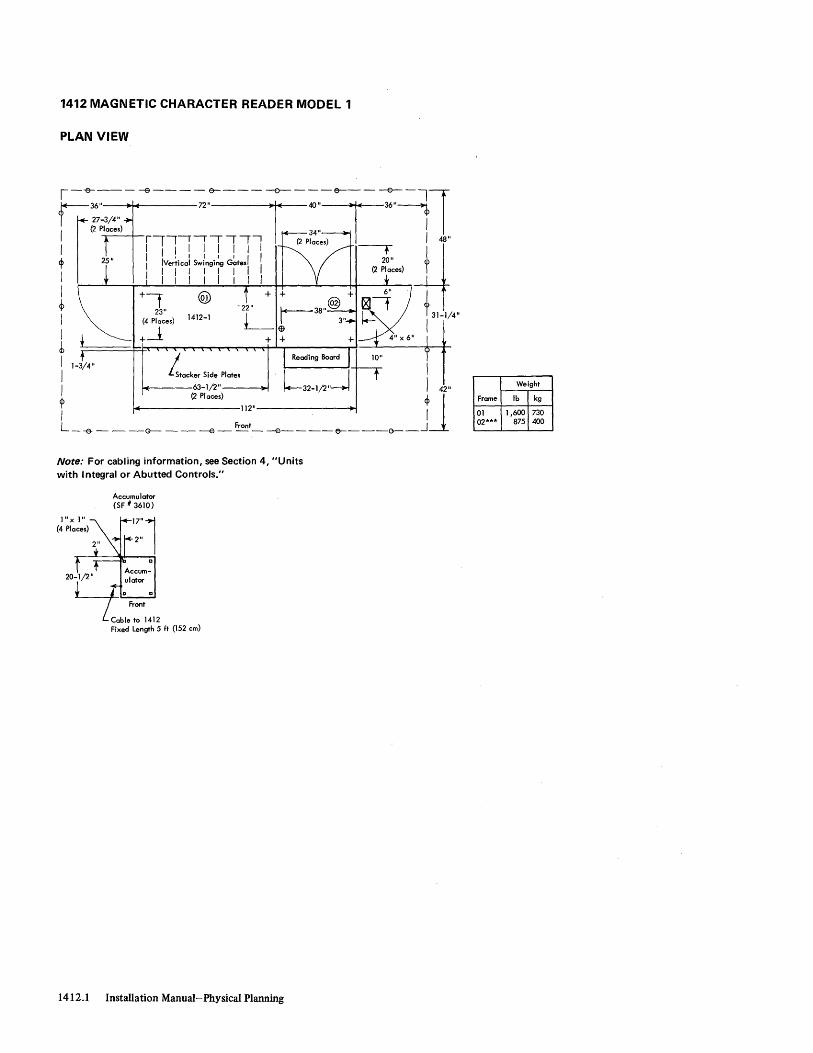
1412 MAGNETIC CHARACTER READER MODEL 1
PLAN VIEW
~r~~/'· ---e------;,'~---___:_I« -:"X&--;-~l I (2 Places) 34"
rlll'!-,--,-! (2 Places) I 48"
I 111IIII11 ~ it ~ 25" I IVertical Swingi~g G~tesl II 20" i I
I 1 I I I I I (2 Places) I I I I 1 I I I I
I +t @ I t 23" 1412-1 i 31-1/4"
I ~~ces} I ~ ~t~~~~~~~~~~-----rl-~--~rT I 1-3/4" I I I LStacker Side Plates
I 63-1/2"----..1 I 42" (2 Places) ~J
</> 112"-------~ I I L _ -e- - - -<r-- - - --e - Front - -e- - --(7--__ ()--_--1
Note: For cabling information, see Section 4, "Units with I ntegral or Abutted Controls."
1" xl" (4 Places)
Accumulator (SF # 361O}
17"l 2"
Accum-
20-~1/2" Qulatar Q
Frant
Cable to 1412 Fixed Length 5 ft (152 cm)
1412.1 Installation Manual-Physical Planning
Weight
Frame Ib kg
01 1,600 730 02*** 875 400
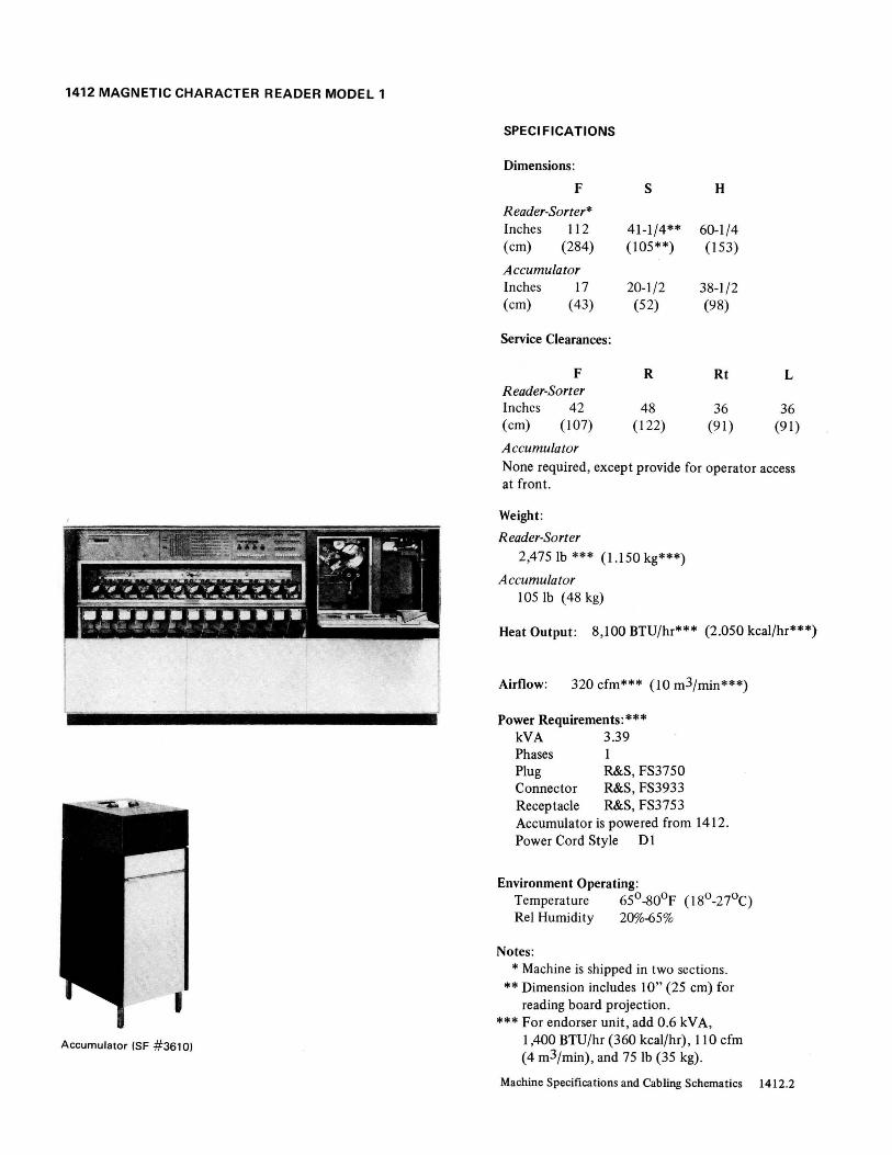
1412 MAGNETIC CHARACTER READER MODEL 1
Accumulator (SF #3610)
SPECI FICATIONS
Dimensions:
F
R eader-Sorter * Inches 112 (cm) (284)
Accumulator Inches 17 (cm) (43)
Service Clearances:
F Reader-Sorter Inches 42 (cm) (107)
A ccumula tor
S
41-1/4** (105**)
20-1/2 (52)
R
48 (122)
H
60-1/4 (153)
38-1/2 (98)
Rt
36 (91)
L
36 (91)
None required, except provide for operator access at front .
Weight:
Reader-Sorter 2,4751b *** (1.150 kg***)
Accumulator 1051b (48 kg)
Heat Output: 8,100 BTU/hr*** (2.050 kcal/hr***)
Airflow: 320 cfm*** (10 m3/min***)
Power Requirements:*** kVA 3.39 Phases 1 Plug R&S, FS3750 Connector R&S, FS3933 Receptacle R&S, FS3753 Accumulator is powered from 1412. Power Cord Style D 1
Environment Operating: Temperature 65° -800F (l80-27°C) Rei Humidity 20%-65%
Notes: * Machine is shipped in two sections.
** Dimension includes 10" (25 cm) for reading board projection.
*** For endorser unit , add 0.6 kV A, 1,400 BTU/hr (360 kcal/hr), 110 cfm (4 m3/min), and 75 Ib (35 kg) .
Machine Specifications and Cabling Schematics 1412.2

1418 OPTICAL CHARACTER READER MODELS 1 TO 3 1428 ALPHAMERIC OPTICAL READER MODELS 1 TO 3
PLAN VIEW
f-;r:~~!4" ---e----,,·~-----:-i~ -:"T€T-7-=11 (2 Places) I
1 IIIIII111 1 48"
" "1'!!!!!"Y~'-H ~ 25 I IVertical Swinging Gatesl II 20 q:>
, I I I I I I I I (2 Places) I
I I I I I I I I I Q + + .,\,. 6" I + ®.- t/V;\ tU
~ r- 6" x 7" I ® I i 1
L/ 1418-1 to 3 23" -+I 31-1/4" ~ 1428-1 to 3 (4 Places) I
, + L+ ~ 11-3/4" U: I Stacker Side Plates
1 63-1/2" 42"
(2 Places) 1 <P 112"------~ , 1
L_-& __ -0-- __ ---e- Front_ -----B----I7--~-()__---l
Note: For cabling information, see Section 4, "Units with I ntegral or Abutted Controls."
Weight Ib (kg)
Models 1 ond 3 Model 2
Frame 1418 1428 1418 1428
01 1,680 1,780 1,730 1,830 (770) (810) (790) (840)
02 970 970 970 970 (440) (440) (440) (440)
1418.1 1428.1 Installation Manual-Physical Planning
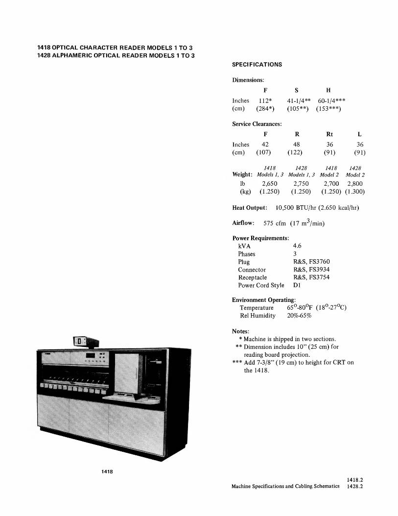
1418 OPTICAL CHARACTER READER MODELS 1 TO 3 1428 ALPHAMERIC OPTICAL READER MODELS 1 TO 3
1418
SPECI FICATIONS
Dimensions :
F S H
Inches 112* 41-1 /4 ** 60-1/4*** (cm) (284*) (I05**) (I53 ***)
Service Clearances:
F R Rt L
Inches 42 48 36 36 (cm) (I 07) (I 22) (91) (91)
1418 1428 1418 1428 Weight : Models 1, 3 Models 1, 3 Model 2 Model 2
Ib 2,650 2,750 2,700 2,800 (kg) (l.250) (l.250) (l.250) (1.300)
Heat Output : 10,500 BTU/hr (2.650 kcal/hr)
Airflow : 575 cfm (I7 m3/min)
Power Requirements: kVA Phases Plug Connector Receptacle Power Cord Style
4.6 3 R&S, FS3760 R&S, FS3934 R&S, FS3754 0 1
Environment Operating: Temperature 65° -800 F ( 18°-27°C) Rei Humidity 20%-65%
Notes: * Machine is shipped in two sections.
** Dimension includes 10" (25 cm) for reading board projection.
*** Add 7-3/8" (l9 cm) to height for CRT on the 1418 .
1418.2 Machine Specifications and Cabling. Schematics 1428 .2

1445 PRINTER MODEL N1
PLAN V IEW
1-- - - &- - - L - Fa,ms- &- - Cabl e Channe l- --G-T l : r- _~~,, ;e, ~~36" i f t" I I r--29" d> I 17 -~ / 8 I I 8" I I I ttl I, I
t 'Leg I" x 7" I ; I 1-1 / 4" ~ I : 8" x 8" I I 20 -1 / 2 " I 1445- NI I I I I L--- L___ I 8 " 43" I I
(3 Places)
j 2-1 / 2" 1 ~ 1-1 / 4" 4- (4 Places) r I 1 'Pdn. Un;' I I -- ----.i I
I 3/ 4" I 1/2" I I J (4 Places}i
l (4 Places) 36" I
I 31 - 7/8" ---I 3-1 / 2" t I (4 Places ) I r 30" -55- 7/8" 48"
Front -.J L -_- G- - - -- - ----£>-~-- -- - -o-
Note: For cabling information, see Section 4, " Units with
I ntegral or Abutted Controls."
SPECIFICATIONS
Dimensions: * F S H
Inches 55-7/8 43 46
(cm) (142) (109) (117)
Service Clearances:
F R Rt
Inches 36 36 48 (cm) (91) (91 ) (122)
Weight: 825 lb (380 kg)
Heat Output: 3,200 BTU/hr (810 kcal/hr)
Airflow: 50 cfm (2 m3/min)
Power Requirements: kVA 1.1 Phases Plug Connector Receptacle Power Cord Style
Environment Operating:
R&S, FS3720 R&S, FS3913 R&S, FS3743 Al
Temperature 60°_90°F (16°-32°C) ReI Humidity 10%-80%
Notes : * Shipping dimensions are 49" x 25" x 50"
(124 cm x 64 cm x 127 cm).
L
30 (76)
Machine Specifications and Cabling Schematics 1445

2167 CONFIGURATION UNIT MODELS 1 TO 4
PLAN VIEW
r--- -e------- --e- --~-1~1 I 7"
Jt[Jf ..
2167.1 Installation Manual- Physical Planning
SPECI FICA TlONS
Dimensions:
F S H
Inches * * 46 (em) (*) (*) (117)
Service Clearances:
F R Rt
Inches * * * (em) (*) (*) (*)
Weight: 583 lb (270 kg)
Heat Output : 2,000 BTU/hr (510 kcal/hr)
Airflow: 500 cfm (15 m3/min)
Power Requirements: kVA 0.65 Phases Plug Connector Receptacle Power Cord Style
R&S , FS3720 R&S, FS3913 R&S, FS3743
A2
Environment Operating: Temperature 60°_90°F (l6o-32°C) ReI Humidity 8o/~0%
Notes: * See plan view.
L
* (*)

2302 DISK STORAGE MODELS 3 AND 4
SPECI FICATIONS
Dimensions:
F S H
Inches 85-1/2* 33 68-3/4 (cm) (217*) (84) (175)
Service Clearances:
F R Rt L
Inches 60 60 60 60 (cm) (152) (152) (152) (152)
Weight : Model 3 Model 4 lb 4,025 4,425
(kg) (1.850) (2.050)
Heat Output: BTU/hr 20,000 28,000 (kcal/hr) (5 .050) (7.100)
Airflow: cfm 2,210 2,210 (m3/min) (63) (63)
Power Requirements: kVA 9.0 12.6 Phases 3 3 Plug R&S, SC7328 Connector R&S, SC7428 Receptacle R&S, SC7324 Power Cord Style E-
Environment Operating: Temperature 65°_90°F (I8o-32°C) Rei Humidity 100/0-80% Max Wet Bulb 78°F (26°C)
Notes: * Machine is shipped in two sections.
Machine Specifications and Cabling Schematics 2302.2

2302 DISK STORAGE MODELS 3 AND 4
PLAN VIEW
'-r-o-------e----------€)-------e----~-l
r I I I I 60" I I 3-1/2" x 19-1/2" t (2 Places) t I I I + I I E9 I ~ 33" 2302-3,4 ~ I I I I I I I I t ~
:[t"" 60" 50-1/8" 35-3/8" 60" .1 ~ --85-1/2" I
L --e-----o----~~-- _-& ____ ~--J ~ Air Intake Area
Note: For cabling information, see 2841 in IBM System/370 Installation Manual-Physical Planning.
585 cfm
(17 m3/min)
525 cfm (15 m 3/min)
100 cfm (3 m 3/min)
1,000 cfm (29 m 3/min )
Airflow
2302.1 Installation Manual-Physical Planning

2167 CONFIGURATION UNIT CABLING SCHEMATIC
2167
~, ~, ~, ~~ J ~ ~,
\.. ./ y
JlO Control Units
Group No. of No. Cables
875 4 876 1
... . .. ,. ... ".
.... ". .... , ... ,.
From
2167 2167
875 876 877 878 879 880
To
2067 2365-12
Max Length (ft) Notes
75 1,6 75 2
877 1 2167 SF #5518 in SF #3846 75 3 878 1 2167 2846 75 4 879 1 2167 2067 75 5 880 3 2167 2067 75 6
Notes: 1. One required to each 2067 when 2167 is used. 2. One required to each 2365 Mode112 when 2167 is used. 3. One required for each 2167 (EPO). 4. One required to each 2846 for up to four 2365 Mode112s. Two required to each 2846 for five or more 2365 Mode112s. 5. One required to 2067 (without SF #5518), EPO. 6. For systems with more than four 2365s, add one group 880 til each 2067.
Machine Specifications and Cabling Schematics 2167.2

2361 CORE STORAGE MODELS 1 AND 2
PLAN VIEW
60"
I I I I
72" r-- 36"
l~1 62-1/4" 30"---.jl
T k---- 90-1/4" -----~ I
L-e-------e------€l------e----e-~
Note: For cabling information, see host CPU.
Weight Airflow Heat Output Frome . BTU/hr kcol/hr
Ib kg cfm m3/min Model 1\ Model 2 Model I \ Model 2
01 625 290 275 8 2,750 I 4,200'· 700 110100 02 1,500 . 690 930 27 8,250 13,200 2.100 3.350
SPECI FICATIONS
Dimensions:
F 8 H
Inches 90-1/4 31-3/4 70-1/2 (cm) (229) (81) (179)
Service Clearances:
F R Rt L
Inches 72 30 30 36 (cm) (183) (76) (76) (91)
Weight: 2,125 lb (970 kg)
Heat Output: Modell Model 2 BTU/hr 11,000 17,400 (kcal/hr) (2.800) (4.400)
Airflow: cfm 1,205 1,205 (m3/min) (35) (35)
Power Requirements: kVA 4.5 7.0 Phases' 3 3 Plug R&8, 8C7328 Connector R&S, SC7428 Receptacle R&s, SC7324 Power Cord Style E3
Environment Operating: Temperature 60°-90°F (16o-32oC) ReI Humidity 8%-80% Max Wet Bulb 78°F (26°C)
Environment Nonoperating: Temperature 50°-110°F (100430C) ReI Humidity 8%-80% Max Wet Bulb 78°F (26°C)
\
Machine Specifications and Cabling Schematics 2361

2365 PROCESSOR STORAGE MODELS 2 AND 3
PLAN VIEW
Note: For cabling information, see host CPU.
Frame Weight
Ib kg
01 870 400 02 1,200 550 03 430 200 04 220 100
2365.1 Installation Manual-Physical Planning
SPECI FICATIONS
Dimensions:
F S H
Inches * * 72-1/2 (cm) (*) (*) (184)
Service Clearances:
F R Rt
Inches * * * (cm) (*) (*) (*)
Weight: 2,7201b (1.250 kg)
Heat Output: 25,300 BTU/hr (6.400 kcal/hr)
Airflow: 1,495 cfm (43 m3/min)
Power Requirements: kVA 7.4 Phases 3 Plug R&S, SC7328 Connector R&S, SC7428 Receptacle R&S, SC7324 Power Cord Style E3
Environment Operating: Temperature 60°-90°F (16° -32°C) ReI Humidity 8%-80% Max Wet Bulb 78°F (26°C)
Notes: * See plan view. Dimensions are for frame
size; add 1-3/8" (4 cm) for each cover. ** SF # 8035 is required with each 2365
Model 2 in a Model 67 system. *** SF # 3846 is an expansion feature that
is required between two 2365 units when not separated by a 2067.
L
* (*)

2365 PROCESSOR STORAGE MODEL 5
PLAN VIEW
I 5-3/ S" I (4 Places)
I ~ I I I
t I I
+
Note: For cabling information, see host CPU .
SPECIFICATIONS
Dimensions:
F S H
Inches 29-1/2 83-3/4 72-1/2 (cm) (75) (213) (184)
Service Clearances:
F R Rt L
Inches 30 30 * * (cm) (76) (76) (*) (*)
Weight: 2,500 1b (1.150 kg)
Heat Output: 15,000 BTU/hr (3.800 kcal/hr)
Airflow: 750 cfm (22 m3/min)
Power Requirements: ** kVA 4.0
Notes: * See plan view.
** Powered from PDU (2085 frame 14).
Machine Specifications and Cabling Schematics 2365.2

2365 PROCESSOR STORAGE MODEL 12
I
PLAN VIEW
(3 Places) r---L __ \ '-'.--""-
30" --k-------"7'.;:::./'-~ /
/
2365-12
@
I I
I ~
43" 43" I Front
--G-------B-------e---1
Note: For cabling information, see host CPU.
Frome Weight
Ib kg
01 870 400 02 1,200 550 03 800 370 04 430 200
2365.3 Installation Manual-Physical Planning
SPECI FICATIONS
Dimensions:
F S H
Inches * * 72-1/2 (cm) (*) (*) (l84)
Service Clearances:
F R Rt L
Inches * * * * (cm) (*) (*) (*) (*)
Weight: 3,3001b (1.500 kg)
Heat Output: 29,000 BTU/hr (7.350 kcal/hr)
Airflow:- 2,345 cfm (67 m3/min)
Power Requirements: kVA 8.5 Phases 3 Plug R&S, SC7328 Connector R&S, SC7428 Receptacle R&S, SC7324 Power Cord Style E3
Environment Operating: Temperature 60°-90°F (16°-32°C) ReI Humidity 8%-80% Max Wet Bulb 78°F (26°C)
Notes: * See plan view. Dimensions are for frame size;
add 1-3/8" (4 cm) for each cover. ** SF #3846 is an expansion feature that is
required between two 2365 units when not separated by a 2067.

2365 PROCESSOR STORAGE MODEL 13
PLAN VIEW
- ----, I
---L_J
3-3/8" I~ 30"
21"
(8 Places) /
/1 62-3/4" I // I
--- <I>
I I I t
Note: For cabling information, see host CPU.
Frame Weight
Ib kg
01 870 400 02 1,200 550 03 430 200 04 220 100
SPECI FICATIONS
Dimensions:
F S H
Inches t t 72-1/2 (em) (t) (t) (184)
Service Clearances:
F R Rt
Inches t t t (em) (t) (t) (t)
Weight: 2,7201b (1.250 kg)
Heat Output: 25,300 BTU/hr (6.400 kcal/hr)
Airflow: 1,495 cfm (43 m3/min)
Power Requirements: kVA 7.4 Phases 3 Plug R&S, SC7328 Connector R&S, SC7428 Receptacle R&S, SC7324 Power Cord Style E3
Environment Operating: Temperature 60o_90°P. (16o-32oC) ReI Humidity 8% .. 80% Max Wet Bulb 78°p (26°C)
Notes: * See Model 65 Multiprocessing Unit cabling
schematic for required usage. ** Required only for 2365 #6, #7, and #8.
*** Required only for 2365 #5 through #8. t See plan view. Dimensions are for frame
size; add 1-3/8" (4 cm) for each cover.
L
t (t)
Machine Specifications and Cabling Schematics 2365.4

2385 PROCESSOR STORAGE MODEL 1
PLAN VIEW (Not 1/4" = l' Scale)
!---~-------1~------~---]
, _ W" I I I I I Ilf W"----+I
I I
!---~------Jl L _______ & __ _
I 60"
<b I I I I I I I I
<1, I 14--36" I I I 4-1/2"
(8 Places) Typical
I dimensions for casters
e? and leveling pods on frames 02,03,04, 05, 06, and 07
I I I I I
<b I
Front
+0
+ Q.. .0 ® 8"
9" x 22" (4 Places) O~ 0 +L::::::::::.:::-1 +
o~d~ I I I
cp
i I) I LIooIr-----------150"------------.J
I I I I
I I
(207-1/4" Cover to Cover)
L - --e- - - - - - - -e - - - - - - - -e - - - - - - -0-
Size (With Covers) Frame
Inches Centimeters
02, 03, 04, 05, 06, 07 34 x 46 86 x 117
01,08,09,11 30 x 60 76 x 152
Note: For cabling information, see host CPU.
2385.1 Installation Manual-Physical Planning
60" I
- - - - - - - G- - - - j - - - -f)---J

2385 PROCESSOR STORAGE MODEL 1
Details (By Frame)
Weight Airflow Ib cfm BTU/hr (kcal/hr)
Frame (kg) (m3/min) To Air To Water
01 1,819 - 3,500 -(830) (890)
02* 1,888 1,400 12,500 10,000 (860) (40) (3.200) (2 .550)
03* 1,679 1,400 12,500 10,000 (770) (40) (3 .200) (2 .550)
04* 1,881 280 12,500 0 (860) (8) (3 .200) (0)
05 * 1,881 280 12,500 0 (860) (8) (3 .200) (0)
06* 1,679 1,400 12,500 10,000 (770) (40) (3 .200) (2.550)
07 * 1,888 1,400 12,500 10,000 (860) (40) (3.200) (2.550)
08 1,581 820 6,400 22,300 (720) (24) (1.650) (5.650)
09 1,246 450 1,640 4,750 (570) (13) (420) (1.200)
10 0 0 0 0 (0) (0) (0) (0)
11 1,679 240 1,210 5,050 (770) (7) (310) (1.300)
SPECI FICATIONS
Dimensions:
F S H
Inches 11<* ** 78 (em) (**) (**) (198)
Service Clearances :
F R Rt L
Inches ** ** ** ** (cm) (**) (**) (**) (**)
Weight : See Details (By Frame)
Heat Output: Air Water
87,750 BTU/hr (22.150 kcal/hr) 72 ,100 BTU/hr (18 .200 keal/hr)
Airflow: 7,670 cfm (220 m3/min)
Power Requirements: The 2385 Modell receives 50/60-Hz and 415/441 -Hz power from the PDU (2085 frame 14).
Environment Operating: Temperature 65°-80°F (180 -27°C) Rei Humidity 200/0-80% Max Wet Bulb 73°F (23 0 C)***
Notes: * The 34" x 46" (86 em x 117 em) frames
cannot be reduced to 29-1 /2" (75 em) for shipping.
** See plan view. *** See "Liquid Coolant System" in Appendix A.
Machine Specifications and Cabling Schematics 2385 .2
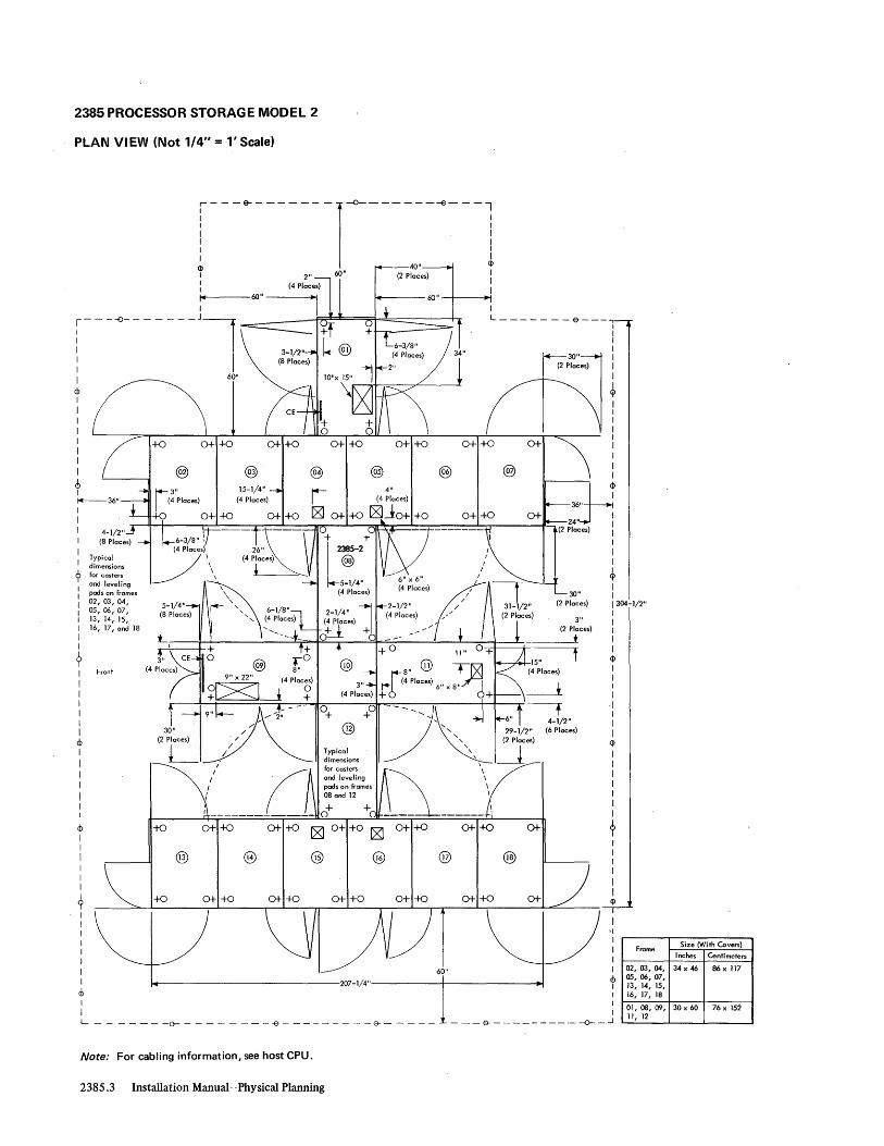
2385 PROCESSOR STORAGE MODEL 2
PLAN VIEW (Not 1/4" = l' Scale)
i---~-------l~------~---l I I I I
<I> f 60" I I I I I Ie 60" ----+I
I
!---~---- --_Jl I 60"
<b I I I I I I I I 6 I iC--36" I I I I
I Typical I dimensions
<} for casters
i ~~s~;~ei:~es I 05,06,07, I 13, 14, 15, I 16, 17, and 18 I I
? I Front
I I I I I I
<b I I I I I I
<b I I
I I I I I 9 I I I I I I I I
cb
+0 0+ +0 0+ +0 0+ +0 0+ +0 0+ +0 0+
@) @ @> @ @ @) 15-1/4"
(4 Places)
+ @) f,0
~1ZI_t PlaC~)
-to 0++0 0+ +0
@
+0 0+ +0
0+ +0 0+- +0 0+
60"
207-1/4"------+-------+1
I I I I I I
<I>
I <!> I I I
I L _______ ~--------~---------&-----
- __ & _________ --0-_...J
Note: For cabling information, see host CPU.
2385.3 Installation Manual-Physical Planning
Frome Size (With Covets)
Inches Centimeters
02,03,04, 34 x 46 86 x 117 OS, 06,07, 13, 14, 15, 16, 17, 18
01,08,09, 30 x 60 76 x 152 11, 12

2385 PROCESSOR STORAGE MODEL 2
Details (By Frame) .
Weight Airflow lb 1m BTU/hr (kcal/hr)
Frame (kg) (m /min) To Air To Water
01 1,819 - 3,500 -(830) (890)
02* 1,888 1,400 12,500 10,000 (860) (40) (3.200) (2.550)
03* 1,679 1,400 12,500 10,000 (770) (40) (3.200) (2.550)
04* 1,881 280 12,500 0 (860) (8) (3.200) (0)
05* 1,881 280 12,500 0 (860) (8) (3.200) (0)
06* 1,679 1,400 12,500 10,000 (770) (40) (3.200) (2.550)
07* 1,888 1,400 12,500 10,000 (860) (40) (3.200) (2.550)
08 1,581 820 6,400 22,300 (720) (24) (1.650) (5.650)
09 1,246 450 3,280 9,500 (570) (13) (830) (2.400)
10 0 0 0 0 (0) (0) (0) (0)
11 2,049 240 2,420 10,100 (930) (7) (610) (2.550)
12 1,581 820 6,400 22,300 (720) (24) (1.650) (5.650)
13* 1,888 1,400 12,500 10,000 (860) (40) (3.200) (2.550)
14* 1,679 1,400 12,500 10,000 (770) (40) (3.200) (2.550)
15* 1,881 280 12,500 0 (860) (8) (3.200) (0)
16* 1,881 280 12,500 0 (860) (8) (3.200) (0)
17* 1,679 1,400 12,500 10,000 (770) (40) (3.200) (2.550)
18* 1,888 1,400 12,500 10,000 (860) (40) (3.200) (2.550)
SPECIFICATIONS
Dimensions:
F. S H
Inches ** ** 78 (em) (**) (**) (198)
Service Clearances:
F R Rt L
Inches ** ** ** ** (em) (**) (**) (**) (**)
Weight: See Details (By Frame)
Heat Output: Air Water
172,000 BTU/hr (43.350 kcal/hr) 144,200 BTU/hr (36.350 kcal/hr)
Airflow: 14,650 cfm (420 m3/rnin)
Power Requirements: The 2385 Model 2 receives 50/60-Hz and 415/441-Hz power from the PDU (2085 frame 14).
Environment Operating: Temperature . 65°-800F (l80-270C) ReI Humidity 20%-80% Max Wet Bulb 73°F (230C)***
Notes: * The 34" x 46" (86 cm-x 117 cm) frames
cannot be reduced to 29-1/2" (75 cm) for shipping.
** See plan view. *** See "Liquid Coolant System" in Appendix A.
Machine Specifications and Cabling Schematics 2385.4

2846 CHANNEL CONT'ROLLER MODEL 1
PLAN VIEW
26"
1
r~3" ~ ~/'''l:- 2846-1
Note: For cabling information, see host CPU.
SPECI FICATIONS
Dimensions:
Inches (cm)
F
* (*)
Service Clearances:
F
Inches 30 (cm) (76)
S
* (*)
R
48 (122)
Weight: 2,0001b (910 kg)
H
72-1/2 (184)
Rt
72 (183)
Heat Output: 2,600 BTU/hr (660 kcal/hr)
Airflow: 900 cfm (26 m3/min)
Power Requirements: kVA 0.88 Phases 1 Plug R&S, PS3720 Connector R&S, PS3913 Receptacle R&S, PS3743 Power Cord Style A2
Environment Operating: Temperature 60° _900 p (16°-32°C) ReI Humidity 8%-80% Max Wet Bulb 780 p (26°C)
Notes: * See plan view.
L
55 (140)
Machine Specifications and Cabling Schematics 2846

3060 SYSTEM CONSOLE MODEL 1 FOR SYSTEM/360 MODEL 195
PLAN VIEW
--"""*,~------104" ------~14--
22"
14-1/2" -'-__
(~I"-=:S)f
1 22" ~ ~
45-3/4"
161-1/2"
71-3/4"
1-' ..L..-..---+--+-----+-t-------===
71" t ---1
Drop-' I down I 5-1/2" Tail- I Gate I (Open) I
. I 59"
14--------151-7/8"--------1-----..
14---------124"'--------~
Note: For cabling information, see 3195.
3060.1 Installation Manual-Physical Planning
22"
(2 Places) I 123-3/4"
13" I (2 Places) SO"
<P 1-1/4" I (2 Places)
I
30"
51-3/4"
!
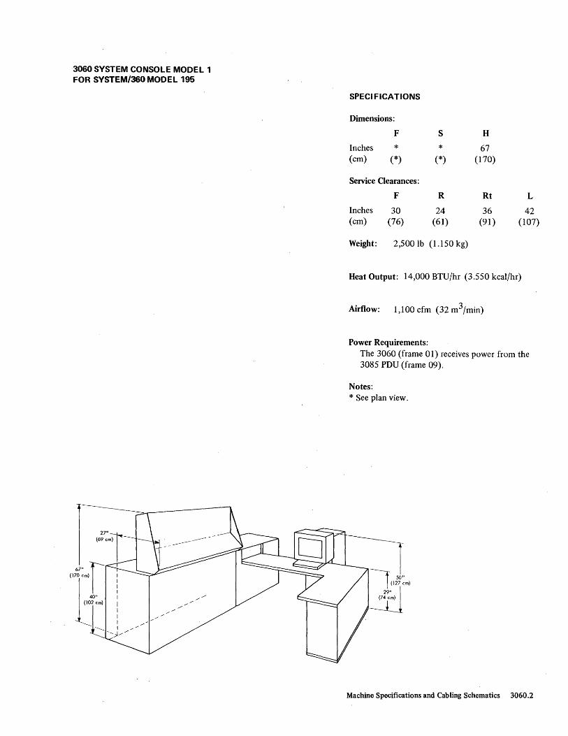
3060 SYSTEM CONSOLE MODEL 1 FOR SYSTEM/360MODEL 195
SPECIFICATIONS
Dimensions:
Inches (cm)
F
* (*)
Service Clearances:
F
Inches 30 (cm) (76)
S
* (*)
R
24 (61)
Weight: 2,5001b (1.150 kg)
H
67 (170)
Rt
36 (91)
L
42 (107)
Heat Output: 14,000 BTU/hr (3.550 kcal/hr)
Airflow: 1,100 cfm (32 m3/min)
Power Requirements: The 3060 (frame 01) receives power from the 3085 PDU (frame 09).
Notes: * See plan view.
Machine Specifications and Cabling Schematics 3060.2

3080 POWER UNIT MODELS 1 TO 3 FOR SYSTEM/3GO MODEL 195
PLAN VIEW
32"
2-7/8" <t>
33-3/4"\ 36"
d1J 15-3/4"
Note: For cabling information, see 3195.
3080, Installation Manual-Physical Planning
SPECI FICATIONS
Dimensions: (All Models)
F S H
Inches 34-1/2 32 60 (cm) (88) (81) (152)
Service Clearances:
Inches (cm)
F
36 (91)
R
24* (61 *)
Rt
24* (61 *)
Weight: 1,300 lb (590 kg) per unit
Heat Output:
BTU/hr (kcal/hr)
Modell 20,000 (5.050)
Water Model 2 14,000 (3.550)
Airflow: 0 cfm (0 m3/min) per unit
P~wer Requirements:
L
24* (61 *)
Model 3 19,000 (4.800)
The 3080 (frames 03, 04, and 05) receives power from 3085 PDU (frame 09).
Notes: One 3195 Processing Unit requires one each of 3080 Power Unit Models 1,2, and 3.
3080 Model Frame Supplies Power for Frame
1 03 06 (Floating Point) 2 04 08 (Fixed Point and VFL Decimal) 3 05 10 (I-unit and SeU)
* No service access required. The 24-inch (61-cm) clearance is shown to assist in distributing machine weight for 75 pounds per square foot (370 kg/m2) floor loading.

3085 POWER DISTRIBUTION UNIT (PDU) MODEL 1 FOR SYSTEM/3GO MODEL 195
PLAN VIEW
r36"
4-1/2" 8" (4 Places)
15-1/2" 1 1 (2 Places) ....I....-.L- r - -e- - -,
Front
3" {76,2 mm} Diameter Clamp*
===cFloor
and Equipment Ground**
Flexible Conduit (Terminate at Clomp)··
Three Conductors (One per Phase) for Sensing and Two Conductors for Indicator Lamp**
.. IBM Supplied ** Customer Supplied. For conductor sizes,
see specifications 'for MG used with Model 195.
U.S.: R&S Plug, 208/230V, 60 Hz WOrid Trade: From Rotory Converter or Customer Outlet
Attachment Cord Assembly (8-ft [244-cm] length)*
Two #18 AWG Conductors for Sensing Indicator Lamp Located in PDU (8-ft [244-cm] length, unterminated)*
Six 10 AWG Conductors (Two per Phase) and One '2 AWG Conductor for Equipment Ground (8-ft[244-cm] length, unterminated)*
Three '16 AWG Conductors for Voltage Sensing; fused in PDU (8-ft [244.,.cm] length, unterminated)*
To Motor Generator
~l ,-1 r--:-----l (f ~ Gnd -..;.<,----4)1-+
1---_--+1-:.,---11- Gnd
,..-, I
~ "
I' II! II } Two Indicator Lamp Five -I-. -+. -4-. ------o--~.-~. ---, Conductors Sen' I I I I I I } ConS~~tors "I I!! Three Sensing Conductors
',,) I . I \,). Separate L - ~ncti~ S;;x- _.J Flexible Conduits Conduit
SPECIFICATIONS
Dimensions:
F S H
Inches 32 32 60 (em) (SI) (SI) (152)
Service Clearances:
F R Rt L
Inches 36 0 36 36 (em) (91) (0) (91) (91)
Weight: 1 ,000 lb (460 kg)
Heat Output: Negligible
Airflow: o cfm (0 m3/min)
Power Requirements: The PDU (frame 09): 1. Receives 20SV, 41S/441-Hz power from
remote motor generator. 2. U. s.
Requires 20SV or 230V, 60-Hz ± O.S-Hz power from customer power panel:
For Model J or K, use 60A service. For Model KJ or L, use 100A service.
World Trade Receives 208V, 60-Hz power from remote rotary converter or customer outlet .
System Model
Requirements JandK KJand L
Plug R&S, SC7328 R&S, JPSI034H
Connector R&S, SC7428 R&S, JCSI034H
Receptacle R&S, SC7324 R&S, JRSRI034H
System SO/60Hz 415/441 Hz Model kVA A/Phase kVA A/Phase
J 10.4 30 47.25 131 K 16.2 45 54.25 151 KJ 21.6 60 64.25 179 L 27.0 75 74.25 206
Machine Specifications and Cabling Schematics 3085

3086 COOLANT DISTRIBUTION UNIT (CDU) MODEL 1 FOR SYSTEM/360 MODE L 195
PLAN VIEW
n=ro--36" 30-3/4"
Cables and Customer Water Supply 6" x 12"
-&----&----&-,
I I ¢
Hoses to Power fL4 PlaCeS)': __ --L-_~-_+_-I_...:~ Frames and CPU I 8" xiS"
I 5" ¢ r (4 ;,o<~) 0 '@'. :
'-1/'" ~ i j" m~) 'wo, JI 1-t --<>,:,: - <> ~ t -~,~~
SPECIFICATIONS
Dimensions:
F S H
Inches 62-1/2 32 70 (cm) (159) (81) (178)
Service Clearances:
F R Rt L
Inches 36 36 36 0 (em) (91) (91) (91) (0)
Weight: 1,450 lb (660 kg)
Heat Output: Air 2,800 BTU/hr (710 keal/hr) , Water 9,000 BTU/hr (2.300 kcal/hr)
Airflow: 0 cfm (0 m3/min)
Environment Operating: Temperature 65°-90°F (18o-32oC) ReI Humidity 20%-80% Max Wet Bulb 72°F (22oC)*
Environment Nonoperating: Temperature 50o-110oF (10°-430 C) ReI Humidity 80/0-80% Max Wet Bulb 80°F (27oC)*
Notes: * See "Liquid Coolant System" in Appendix A.
Machine Specifications and Cabling Schematics 3086

7772 AUDIO RESPONSE UNIT MODEL 3
PLAN VIEW SPECI FICATIONS
Dimensions:
F S H
Inches 37-1/2 31-1/2 70 (cm) (95) (80) (178)
Service Clearances:
I - - a-- - - - 0- - - -E) - T I I 23-7/ 8" 12 " 1 l4 Places) 36" I )' End (4 Place. ) r
Covers I 3/ 4" I
I '" I f f F R Rt L
Inches 42 36 30* 30* (cm) (107) (91) (76*) (76*)
1 I
~ ~ I I 1 2" I Weight: 600lb (280 kg)
~ 26-1/2" ~ I (2 Places) 32" 30" ---J
tt42 " (2 Places) I
30" 37- 1/2" L -e-----€)----e--~
Heat Output: 5,100 BTU/hr (1.300 kcal/hr)
Airflow: 1,800 cfm (51 m3/min)
Power Requirements: kVA 2.0 Phases Plug R&S, FS3720 Connector R&S, FS3913 Receptacle R&S, FS3743 Power Cord Style A3
Environment Operating: Temperature 60°-90°F (160 -32°C) ReI Humidity 80/0-80% Max Wet Bulb 78°F (26°C)
Environment Nonoperating: Temperature 50°_110°F (10°-43°C) ReI Humidity 0%-90% Max Wet Bulb 80°F (27°e)
Notes: * When not abutted to another similar module.
7772.1 Installation Manual-Physical Planning

7772 AUDIO RESPONSE UNIT CABLING SCHEMATIC
650
651
652
654
Group No.
650 651 652
_' Multiplexer Channel " J Other Control Units ~
J Sequence and Control (EPO) 7772 ,.
oJ Channel-to-Channel Adapter
-
No. of Cables From
2 7772 2 7772 1 7772
653 (or 655) 2 Data Set 654 2 7772
Notes:
.- 653 (or 655 "
) Data Set
Max To Length (ft)
Multiplexer Channel Control Unit Channel 100 7772 40 Channel-to-Channel Adapter
1. Total cable length of 200 feet (unless modified by general control-to-channel cabling schematic) available to attach up to eight control units.
2. Sequence and control (EPO). 3. To channel-to-channel adapter (SF #1850). 4. One group for each pair of data sets. 5. See "Cables from Non-IBM Devices" for cable specifications. 6. For 50-Hz machines, use group number in parentheses.
Cables from Non-IBM Devices
653 ----------------------~
----------------------~ 2 EIA RS-232A Connectors
655 { -----------ctl:< ------------~
2 cCin Connectors
Notes
1 1 2 4,5,6 1,3
Machine Specifications and Cabling Schematics 7772.2

Section 4. General Cabling Information
GENERAL CONTROL-TO-CHANNEL CABLING
Generally, the cable available to connect up to eight control units to a channel is limitep to 200 feet (100 feet for System/360 Models 22, 25, and 30). Exceptions to this are noted on the cabling schematics for the individual control units. All control units are connected to the channels serially. All channels exceeding 100 feet must be reviewed and approved by the Installation Planning representative.
-I -I ~
Channel 1 * I Channel 2
~
I' Sequence and --{ Control (EPO) ,
(1 Each Control Position)
~- - ....
.... - --4 , , --
/
Control "---- Unit
#1**
~
I Control Unit #2 (With
Two-Channel Capability)
~ , Control
Unit #,3
1~
~
I/O I nterface Cables -....
Control Unit #1**
• Control
Unit
#3
J To Additional/ Control Units (Max 8)
*The channel may be a separate unit (such as the IBM 2860) or integral to the system processing unit.
**Units with two-byte interface feature must be installed first on the channel.
/ ( , -- -, ,
\- - - Sequence and
.... - -- / Control (EPO)
General Cabling Information 4.1

CHANNEL-TO-CHANNEL ADAPTER CABLING
The channel-to-channel adapter (SF #1850) is considered as though it were a control unit on each of the channels involved. The adapter requires external cables to a control unit or channel of the second system. The adapter is instilled with the channel, either in a separate unit (such as the 2860) or physically in the central processing unit. It may be assigned to any control unit position on the guest channel. The adapter is assigned to the first control unit position on the host channel; the cable attaching it to the charinel is specified as "X" length of "0" feet.
r-------------, I I I I I Channel 1 Channel 2 I
I I
I Control Unit Control Unit
Specify "X" Length As "0" Feet #1 #3
I L ______ o __________ .....J
Control Unit #2
Control Unit
#3
* X refers to the host channel; Y refers to the guest channel.
4.2 Installation Manual-Physical Planning
Control Unit
#1
Control Unit #2
Control Unit
#4
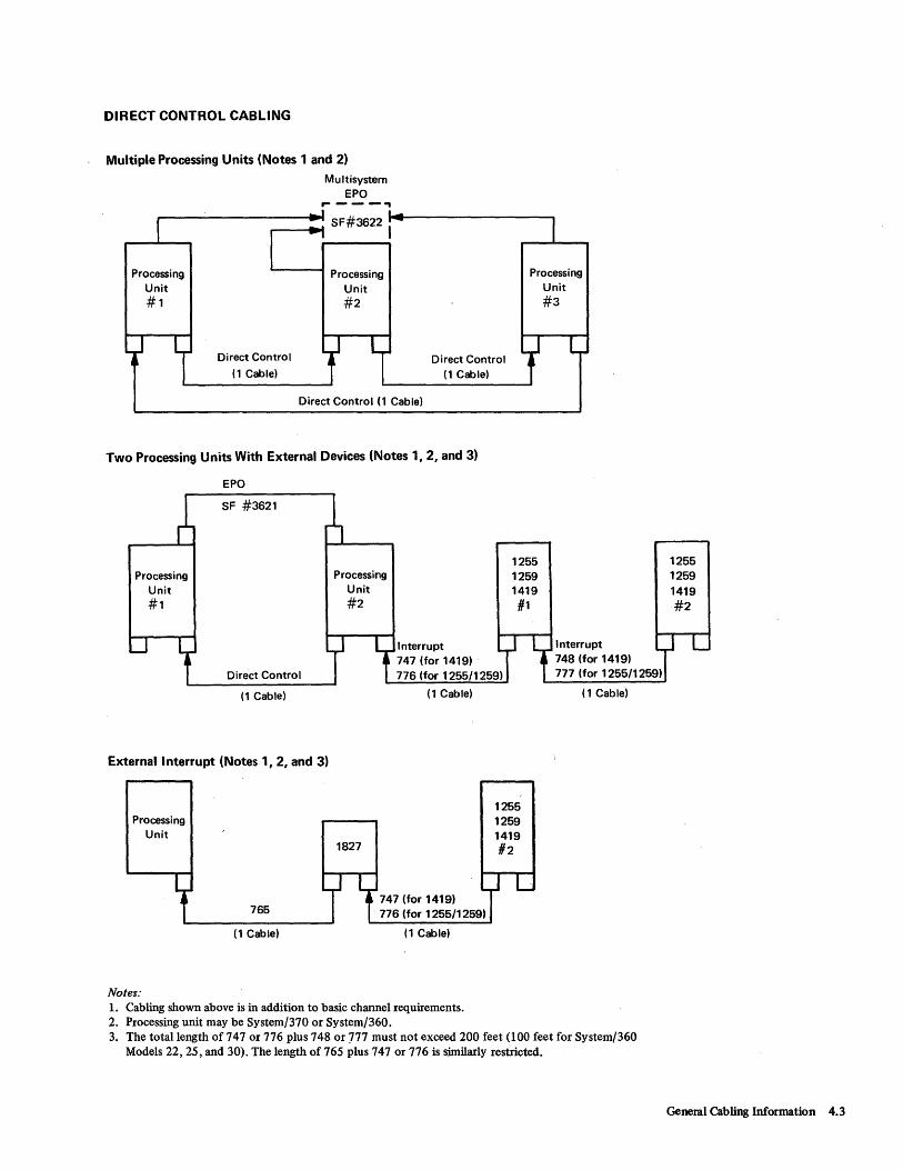
DIRECT CONTROL CABLING
Multiple Processing Units (Notes 1 and 2) Multisystem
EPO
Processing Unit #1
.----., ....---..... SF#3622 I
Processing Unit #2
Processing Unit #3
Direct Control
(1 Cable) Direct Control
(1 Cable)
Direct Control (1 Cable)
Two Processing Units With External Devices (Notes 1, 2, and 3)
EPO
Processing Unit #1
SF #3621
Processing Unit #2
Interrupt 747 (for 1419)
1255 1259 1419 #1
Direct Control 776 (for 1255/1259)
(1 Cable)
External Interrupt (Notes 1, 2, and 3)
Processing Unit
Notes:
765
(1 Cable)
(1 Cable)
1827
(1 Cable)
1. Cabling shown above is in addition to basic channel requirements. 2. Processing unit may be System/370 or System/360.
1255 1259 1419 #2
Interrupt 748 (for 1419) 777 (for 1255/1259)
(1 Cable)
3. The total length of 747 or 776 plus 748 or 777 must not exceed 200 feet (100 feet for System/360 Models 22, 25, and 30). The length of 765 plus 747 or 776 is similarly restricted.
1255 1259 1419 #2
General Cabling Information 4.3
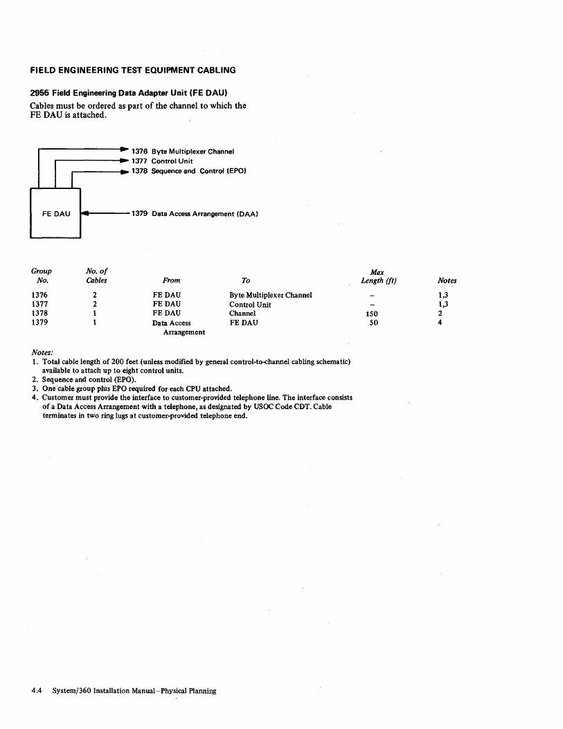
FIELD ENG INEERING TEST EQUIPMENT CABLING
2955 Field Engineering Data Adapter Unit (FE DAU)
Cables must be ordered as part of the channel to which the FE DAU is attached.
I FE DAU --
Group No. 01 No. Cables
1376 2 1377 2 1378 1 1379 1
Notes.;
.. ---
1376 Byte Multiplexer Channel 1377 Control Unit 1378 Sequence and Controt (EPO)
1379 Data Access Arrangement (DAA)
From To
FEDAU Byte Multiplexer Channel FEDAU Control Unit FEDAU Channel Data Access FEDAU
Arrangement
1. Total cable length of 200 feet (unless modified by general control-to-channel cabling schematic) available to attach up to eight control units.
2. Sequence and control (EPO). 3. One cable group plus EPO required for each CPU attached. 4. Customer must provide the interface to customer-provided telephone line. The interface consists
of a Data Access Arrangement with a telephone, as designated by USOC Code CDT. Cable terminates in two ring lugs at customer-provided telephone end.
4.4 System/360 Installation Manual-Physical Planning
Max Length (It) Notes
1,3 1,3
150 2 50 4

UNITS WITH INTEGRAL OR ABUTTED CONTROLS
712 715 702 706 713 716 746 707 714 717 747 708 722 723 1412 748 720
1231 754 1285 755 1418 1445 735 1428
Group No. of Max No. Cables From To Length (ft) Notes
702 1 Reader Unit Channel 150 2 706 2 1445 Selector Channel 1 707 2 1445 Control Unit 1 708 1 1445 Channel 150 2 712 2 1231 Multiplexer Channel 1 713 2 1231 Control Unit 1 714 1 1231 Channel 150 2 715 2 1285 Multiplexer Channel 716 2 1285 Control Unit 1 717 1 1285 Channel 150 2 720 2 1445 Channel-to-Channel Adapter 1,3 722 2 1231 Channel-to-Channel Adapter 1,3 723 2 1285 Channel-to-Channel Adapter 1,3 735 2 1445 Multiplexer Channel 1 746 2 Reader Unit Selector Channel 1,6 747 1 Reader Unit System/360 CPU 4,5 748 1 Reader Unit Reader Unit 4,5 754 2 1231 Selector Channel 1 755 2 1285 Selector Channel 1
Notes: 1. Total cable length of 200 feet (unless modified by general.<control-to-channel cabling schematic) available to attach
up to eight control units. 2. Sequence and control (EPO). 3. To channel-to-channeladapter (SF #1850). 4. For SF #3895 or SF #3274 on System/360 CPU. 5. 200 feet (unless modified by direct control cabling schematic) total length of 747 plus 748. 6. For use with all 1412, 1418, and 1428 machines with SF #7720 (single address).
General Cabling Information 4.5
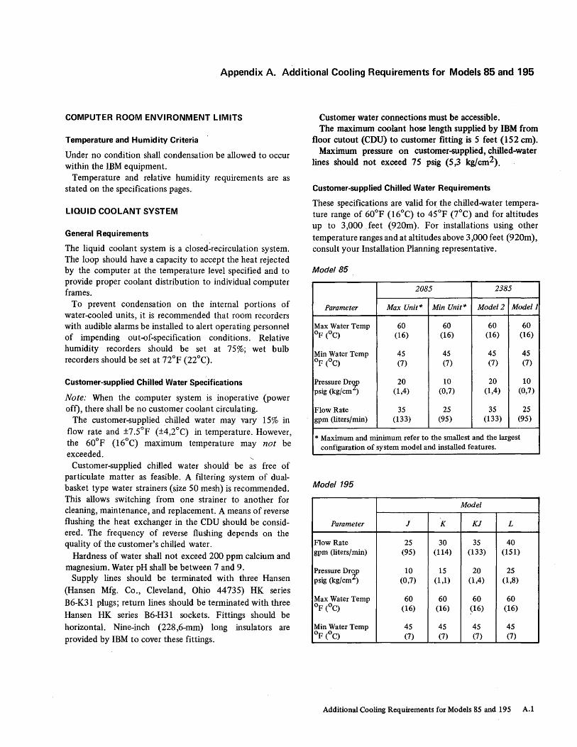
Appendix A. Additional Cooling Requirements for Models 85 and 195
COMPUTER ROOM ENVIRONMENT LIMITS
Temperature and Humidity Criteria
Under no condition shall condensation be allowed to occur within the IBM equipment.
Temperature and relative humidity requirements are as stated on the specifications pages.
LIQUID COOLANT SYSTEM
General Requirements
The liquid coolant system is a closed-recirculation system. The loop should have a capacity to accept the heat rejected by the computer at the temperature level specified and to provide proper coolant distribution to individual computer frames.
To prevent condensation on the internal portions of water-cooled units, it is recommended that room recorders with audible alarms be installed to alert operating personnel of impending out-of-specification conditions. Relative humidity recorders should be set at 75%; wet bulb recorders should be set at 72°F (22°C).
Customer-supplied Chilled Water Specifications
Note: When the computer system is inoperative (power oft), there shall be no customer coolant circulating.
The customer-supplied chilled water may vary 15% in flow rate and ±7.5°F (±4,2°C) in temperature. However, the 60°F (16°C) maximum temperature may not be exceeded.
Customer-supplied chilled water should be as free of particulate matter as feasible. A filtering system of dualbasket type water strainers (size 50 mesh) is recommended. This allows switching from one strainer to another for cleaning, maintenance, and replacement. A means of reverse flushing the heat exchanger in the CDU should be considered. The frequency of reverse flushing depends on the quality of the customer's chilled water.
Hardness of water shall not exceed 200 ppm calcium and magnesium. Water pH shall be between 7 and 9.
Supply lines should be terminated with three Hansen (Hansen Mfg. Co., Cleveland, Ohio 44735) HK series B6-K31 plugs; return lines should be terminated with three Hansen HK series B6-H31 sockets. Fittings should be horizontal. Nine-inch (228,6-mm) long insulators are provided by IBM to cover these fittings.
Customer water connections must be accessible. The maximum co()lant hose length supplied by IBM from
floor cutout (CDU) to customer fitting is 5 feet (152 cm). Maximum pressure on customer-supplied, chilled-water
lines should not exceed 75 psig (5,3 kg/cm2).
Customer-supplied Chilled Water Requirements
These specifications are valid for the chilled-water temperature range of 60°F (16°C) to 45°F (7°C) and for altitudes up to 3,000 Jeet (920m). For installations using other temperature ranges and at altitudes above 3,000 feet (920m), consult your Installation Planning representative.
Model 85
2085 2385
Parameter Max Unit* Min Unit* Model 2 Modell
Max Water Temp 60 60 60 60 0p (0C) (16) (16) (16) (16)
Min Water Temp 45 45 45 45 0p (0C) (7) (7) (7) (7)
Pressure Dr~ 20 10 20 10 psig (kg/em) (1,4) (0,7) (1,4) (0,7)
Plow Rate 35 25 35 25 gpm (liters/min) (133) (95) (133) (95)
* Maximum and minimum refer to the smallest and the largest configuration of system model and installed features.
Model 195
Model
Parameter J K KJ L
Flow Rate 25 30 35 40 gpm (liters/min) (95) (114) (133) (151)
Pressure Dr~ 10 15 20 25 psig (kg/em ) (0,7) (1,1) (1,4) (1,8)
Max Water Temp 60 60 60 60 0p (0C) (16) (16) (16) (16)
Min Water Temp 45 45 45 45 0p (oC) (7) (7) (7) (7)
Additional Cooling Requirements for Models 85 and 195 A.l

COOLANT DISTRIBUTION UNIT FOR SYSTEM/3GO 2085 AND 2385
Jl Water connections should 34" be made in this area
10"·x IS" J.--, / \ " 61"\
~~/ 2" -l ~ ;- Approximate location where --.- -~ six I-inch 10 hoses (2-5/8
L., ~ ____ . ..J, inches 00) go through floor . 30" to connect to customer water
Typical Connections for Customer-supplied Chilled Water for Models 85 and 195
Floor Cutout under CDU
* IBM Supplied ** Customer Supplied
A.2 Installation Manual-Physical Planning
Shut-off Valves
(2) **
5-foot (152-cm) Long Hose Assembly (6) *
Plug

Appendix B. Input/Output Device Priority Considerations
I/O Device Class
1231-N1 1
1285
1412 1
1418 1
1428 1
1445 3
2955 1
7772 1
Byte Multiplexer Channel Critical Time (ms)
11.00
0.40
0.86
18.50
14.1/N
Input Manual *
No.
3.30
IBM 1001
1.48
* Manual = pushbutton; manual dialing telephone.
Notes:
Block Multiplexer and Selector Channel Burst Mode Data Rate (per second)
150 characters
760 characters
Mpxr only
Mpxr only
Mpxr only
90,000 characters
Mpxr only
Mpxr only
Notes (Listed at End of Table)
2,3
2,3
2
1. Is generally attached to the lowest priority (highest numbered) selector channe1. The adapter must be the first control device on the channel to which it is assigned and must also have first priority.
2 .. In general, this' device should be placed in highest channel priority. However, because of the load imposed on the channel by one or more of these devices as a function of how the device is programmed, it may be necessary for another device to be placed in higher priority.
3. Only one per system.
Input/Output Device Priority Considerations B.1

Appendix C. Power Cord Style Specifications and Plug Installation (World Trade Reference)
CABLE SPECIFICATIONS
Power Cable Number Conductors Cord NominalOD of NominalOD* Style inches (mm) Shields Quantity inches (mm)
Al 0.520 (13,2) 1 3 0.064 (1,6) A2 0.510 (13,0) 1 3 0.081 (2,1) A3 0.570 (14,5) 1 3 0.102 (2,6) A4 0.375 (9,5) 1 3 0.051 (1,3) A5 0.390 (9,9) 0 3 0.051 (1,3) A6 0.560 (14,2) 0 3 0.064 (1,6) A8 0.390 (9,9) 0 3 0.064 (1,6) A9 0.374 (9,5) 0 3 0.040 (1,0)
Bl 0.7l3 (18,1) 0 5 0.102 (2,6)_ B2 0.693 (17,6) 1 5 0.064 (1,6)
Dl· 0.792 (20,1) 2 5 0.102 (2,6) D2 0.750 (19,0) 1 5 0.102 (2,6) D3 0.642 (16,3) 2 5 0.064 (1,6)
El 1.024 (26,0) 1 5 0.129 (3,3) E2 1.400 (35,6) 0 5 0.232 (5,9) E3 1.200 (30,5) 2 5 0.184 (4,7) E4 1.200 (30,5) 0 5 0.184 (4,7) E5 1.200 (30,5) 1 5 0.184 (4,7) E6 1.240 (31,5) 2 4 0.184 (4,7) E7 1.440 (36,6) 1 5 0.232 (5,9) E8 0.974 (24,7) 0 5 0.129 (3,3) E9 0.949 (24,1) 1 4 0.184 (4,7) EI0 1.340 (34,0) 1 4 0.232 (5,9)
Fl 1.400 (35,6) 0 5 0.292 (7,4) F2 1.646 (41,8) 1 5 0.292 (7,4) F3 1.646 (41,8) 0 5 0.292 (7,4) F4 1.293 (32,8) 1 4 0.292 (7,4)
Gl 3 0.040 (1,0) G2 G3 0.360 (9,1) 0 - 0.051 (1,3) G4 0.365 (9,3) 1 - 0.040 (1,0)
* This diameter refers to solid, bare wire.
HOW TO INSTALL A POWER PLUG ON SHIELDED CABLE .
To make power cable shielding effective, the shield or shields, must be properly terminated at the plug end of the cable. Because different plugs are used in different countries, s1ight changes to the following instructions may be needed.
Names of Bulk Cable Components
Outer Jacket Inner Shield
Core Mylar Separator (Only in two-shield cable)
Outer Shield (Only in two-shield cable)
AWG No.
14 12 10 16 16 14 14 18
10 14
10 10 14
8 4 6 6 6 6 4 8 6 4
2 2 2 2
18
16 18
Preparing Bulk Cable End for the Plug
Dimensions given are for reference only. The installer is to use his own discretion to assure proper assembly of the cable and plug.
Step 1: Remove outer jacket for 1-1/2 inches (38 mm) from end for lSA-30A cables or 2-3/4 inches (70 mm) from end for 45A-60A cables. If this is a one-shield cable, go to step 4.
Step 2: (For two-shield cables only.) Remove the outer shield as far back as the outer jacket. The Mylar separator is exposed. Wrap one full turn of electrical tape over the separator and another full turn of tape over the cut end of the outer shield; overlap onto the outer jacket. This tape is used to assure complete electrical isolation between the inner and the outer shields. (See 0.)
Power Cord Style Specifications and Plug Installation C.1
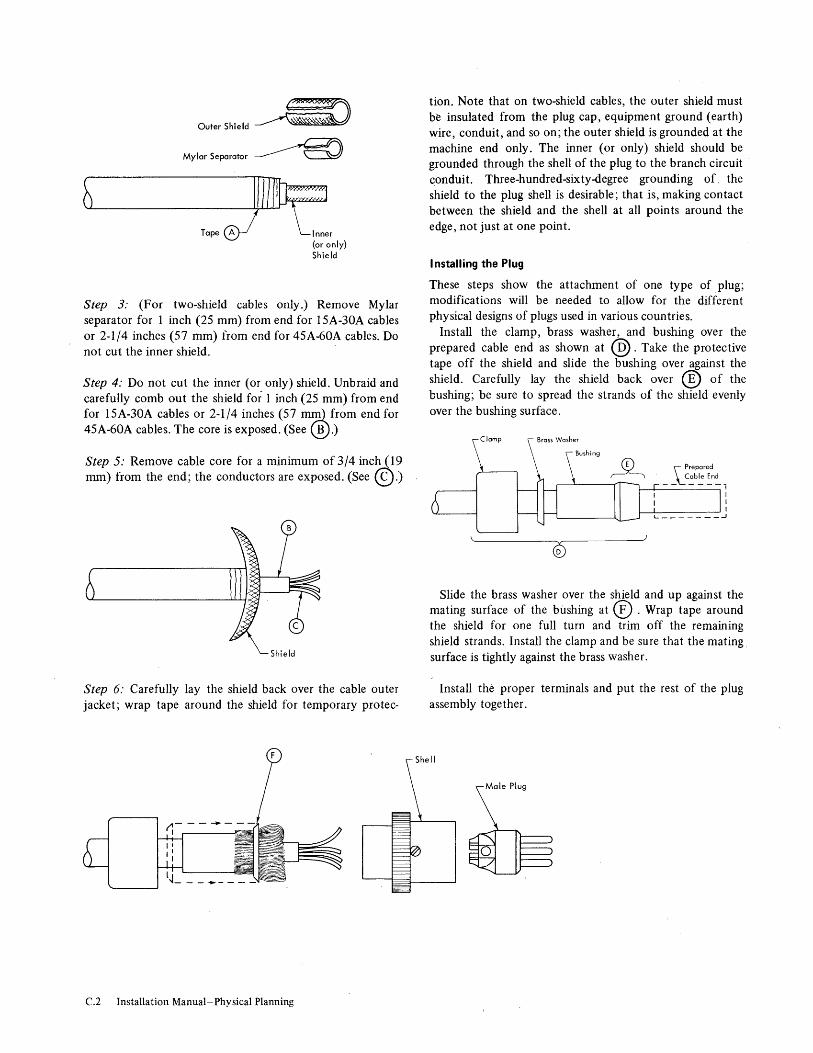
O Sh' Id ~ilITO uter Ie
Mylar Separator ~
@)1I~:~1 Tape A Inner
(or only) Shield
Step 3: (For two-shield cables only.) Remove Mylar separator for 1 inch (25 mm) from end for 15A-30A cables or 2-1/4 inches (57 mm) from end for 45A-60A cables. Do not cut the inner shield.
Step 4: Do not cut the inner (or only) shield. Unbraid and carefully comb out the shield for 1 inch (25 mm) from end for 15A-30A cables or 2-1/4 inches (57 mIJU.. from end for 45A-60Acables. The core is exposed. (See ®.)
Step 5: Remove cable core for a minimum of 3/4 inch (19 mm) from the end; the conductors are exposed. (See ©.)
Shield
Step 6: Carefully lay the shield back over the cable outer jacket; wrap tape around the shield for temporary protec-
C.2 Installation Manual-Physical Planning
tion. Note that on two-shield cables, the outer shield must be insulated from the plug cap, equipment ground (earth) wire, conduit, and so on; the outer shield is grounded at the machine end only. The inner (or only) shield should be grounded through the shell of the plug to the branch circuit conduit. Three-hundred-sixty-degree grounding of, the shield to the plug shell is desirable; that is, making contact between the shield and the shell at all points around the edge, not just at one point.
I nstalling the Plug
These steps show the attachment of one type of plug; modifications will be needed to allow for the different physical designs of plugs used in various countries.
Install the clamp, brass washer, and bushing over the prepared cable end as shown at @. Take the protective tape off the shield and slide the bushing over against the shield. Carefully lay the shield back over ® of the bushing; be sure to spread the strands of the shield evenly over the bushing surface.
Slide the brass washer over the shield and up against the mating surface of the bushing at ® . Wrap tape around the shield for one full turn and trim off the remaining shield strands. Install the clamp and be sure that the mating, surface is tightly against the brass washer.
Install the proper terminals and put the rest of the plug assembly together.

Appendix D. Template Index
Type Model Order (Form) Number Type Model Order (Form) Number
2030 GX22-6894, 360 and 370 Field Engineering
Furniture and Test 2040 GX22-6894 Equipment GX22-6925
2044 E-H GX22-6914 360 22 See 2022
2050 F-H GX22-6914 360 25 See 2025
2050 HG, I GX22-6914 360 30 See 2030
2065 H, I GX22-6856 360 40 See 2040
2065 IH,J GX22-6856 360 44 E-H See 2044 E-H
2065 I (MP) GX22-6924 360 50 F-H See 2050 F-H
2065 IH (MP) GX22-6924 360 50 HG, I See 2050 HG, I
2065 J (MP) GX22-6924 360 65 H, I See 2065 H, I
2067 GX22-6905 360 65 IH, J See 2065 IH, J
2075 H, I GX22-6856 360 65 I (MP) See 2065 I (MP)
2075 IH, J GX22-6856 360 65 IH (MP) See 2065 IH (MP)
2085 GX22-6923 360 65 J (MP) See 2065 J (MP)
2167 14 GX22-6905 360 67 See 2067
2302 3,4 GX22-6858 360 75 H, I See 2075 H, I
2361 1,2 GX22-6856 360 75 IH; J See 2075 IH, J
2365 2,3 GX22-6856 360 85 See 2085 GX22-6905
360 195 J, K, KJ, L See 3195 2365 5 GX22-6923
1051 1, N1 GX24-6894 2365 12 GX22-6905
1231 N1 GX22-6860 2365 13 GX22-6924
1285 GX22-6860 2385 1,2 GX22-6923
1404 2 GX22-6834 2846 GX22-690S
1412 GX22-6860 3060 GX22-6981
1418 1-3 GX22-6860 3080 1-3 GX22-6981
1428 1-3 GX22-6860 3085 GX22-6981
1445 N1 GX22-6834 3086 GX22-6981
2022 GX22-6894 3195 J, K, KJ, L GX22-6981
2025 GX22-6894 7772 3 GX22-6857
Template Index D.1

WT U S I
WT U S
WT
I w T
Type
360 360 360
360 360 360
360 360 360
360 360 360
360 360 360
360 360 360
360 360 360
360 360 360
360 360 360
360 360 360
360 360 360
1051 1231 1285
1404 1412 1418
1418 1428 1428
1445 2167 2302
2302 2361 2361
2365 2365 2365
2365 2385 2385
2846 3060 3080
3085 3086 7712
Model
22 25 30
40D-G 40GF,H 44E,F
44G 44H 50F.G
SOH 50HG 50I
65H.I 65IH.J 65I
65IH 65J 67
75H.I 15IH.J 85
85 85 85
85 85 195J
195K 195KJ 195L
195 195 195
l,Nl Nl 1
2 1 1,3
2 1,3 2
N1 1-4 3
4 1 2
2,3 5 12
13 1 2
1 1 1-3
1 1 3
Descri pti on kVA
2022 Processing Unit 2.4 2025 Processing Unit 7.4 2030 Processing Unit 3.8
2040 Processing Unit 2.5 2040 Processing unit 3.7 2044 Processing Unit 5.3
2044 Processing Unit 6.5 2044 Processing Unit 9.5 2050 Processing Unit 6.5
2050 Processing Unit 6.8 2050 Processing Unit 7.0 2050 Processing Unit 7.6
2065 Processing Unit 5.4 2065 Processing Unit 5.4 Multiprocessing Unit 5.4
Multiprocessing Unit 5.4 Multiprocessing Unit 5.4 2067 Processing Unit 6.85
2075 Processing Unit 2015 Processing Unit 2085 Processing Unit
Power Dist Unit (2085) MG Starter (Remote) MG Starter (Remote)
MG (Remote) MG (Remote) 3195 Proc unit • Stg
3195 Proc Unit • Stg 3195 Proc Unit • Stg 3195 Proc Unit • stg
MG (Remote) MG (Remote) Rotary ConY (Remote)
Control Unit 0.2 Optical Mark Page Rdr 1.2 Optical. Reader 1.8
Printer 1.5 Magnetic Character Rdr 3.39 Optical Character Rdr 4.6
Optical Character Rdr 4.6 Alphameric Optical Rdr 4.6 Alphameric Optical Rdr 4.6
Printer 1.1 Configuration Unit 0.65 Disk Storage 9.0
Disk Storage 12.6 Core Storage 4.5 Core storage 7.0
Processor Storage 7.4 Processor Storage 4.0 Processor storage 8.5
Processor Storage 7.4 Processor storage Processor Storage
Channel Controller 0.88 System Console Power unit
Power Dist Unit Coolant Dist unit Audio Response Unit 2.0
Appendix E. System/360 Specification Summary (English Units)
Electrical Environmental Notes Service (Listed
Dimensions Clearances at End Pwr (inches) (inches) of Table Cord Conn Weight Style Note BTU/hr cfm (Ib) Front Side ,Height F R Rt L
D3 B 6.900 900 1.500 60 1.2 E- E 20.500 800 2.050 60 1.2 D3 B 10.000 900 1,700 60 1-3
Bl D 1,000 300 1.700 60 1-3 Bl D 10,500 300 2,310 70 1-3 El D 15,000 1 .. 600 2,900 72 1-3
El D 19,0<10 1,600 2,900 72 1-3 El (2) D(2) 28.000 2,400 4,200 72 1-3,6 E3 E 20,410 2.350 4,700 \ 72-112 1.2
E3 E 21.350 2,990 5,385 12-1/2 1-3 E3 E 24.000 4,600 7,135 72-112 1--3 E3 E 25.000 4.600 7,135 72-112 1-3
El E 15.800 2,100 4,290 72-1/2 1.2 El E 15.800 2,100 5,190 72-112 1.2 El E 15.800 2.100 8,170 72-112 1,2
El E 15.800 2.100 8,500 72-1/2 1.2 E1 E 15.800 2.100 8,83.0 72-1/2 1.2 El E 20.000 4.620 3,614 72-112 1.2
E3 E 21.600 3,350 5,125 72-1/2 1-3 E3 E 27.600 3.350 5,325 72-112 1-3 D3 D 3.100 14,428 78 1-3
0 1,500 30 60 70 36 36 30 30 1-3 30 30 0 0 1 30 30 0 0 1
102,000 4,630 100 34 53 30 30 30 30 1 4,200 86 34 53 30 30 30 30 1
4.700 13,450 70 1-3
7.500 18,750 70 1-3 10,300 24,850 70 1-3 13,100 28,350 70 1-3
55,250 3,600 81 36 51 30 30 30 30 1 40,000 3,000 76 37 54 30 30 30 30 1 72,915 1,550 56 36 37 30 30 30 30 1
A5 A 610 0 195 26 15 27 0 36 0 30 Al A 3,700 300 620 43-1/2 24 44-3/4 42 42 30 36 3 D1 D 5,000 600 1,600 7"-1/4 35-3/4 60 36 48 42 48
3,800 280 1,600 67-1/8 31-3/4 53-1/2 36 36 48 42 4 Dl C 8,100 320 2,475 112 41-1/4 60-1/4 42 48 36 36 5 Dl D 10,500 575 2,650 112 41-1/4 60-1/4 42 48 36 36 5
D1 D 10,500 575 2,100 112 41-1/4 60-1/4 42 48 36 36 5 Dl D 10,500 515 2,150 112 41-1/11 60-1/4 42 48 36 36 5 Dl D 10,500 575 2,800 112 41-1/4 60-1/4 4.2 48 36 36 5
A1 A 3,200 50 825 55-1/8 43 46 36 36 48 30 A2 A 2,000 500 583 46 1 E- E 20,000 2,210 4,025 85-1/2 33 68-3/4 60 60 60 60 3-5,7
E- E 28,000 2,210 4,425 85-1/2 33 68-3/4 60 60 60 60 3-5,7 E3 E 11,000 1,205 2,125 90-1/4 31-3/4 10-1/2 72 30 30 36 3 E3 E 17 .400 1,205 2,125 90-1/4 31-3/4 10-112 72 30 30 36 3
E3 E 25.300 1,495 2.120 72-1/2 1 15,000 750 2,500 29-1/2 83-3/11 72-1/2 30 30 1,4
E3 E 29,000 2,345 3,300 72-1/2 1
E3 E 25,300 1,495 2,120 12-1/2 1 7,670 78 1
14,650 78 1
A2 A 2,600 900 2,000 72-1/2 30 48 12 55 1 14.~00 1,100 2.500 67 30 24 36 42 1.3,4
0 1,300 34-1/2 32 60 36 1,3,4
0 1,000 32 32 60 36 0 36 36 1.3 0 1.450 62-1/2 32 70 36 36 36 0 1,3
A3 A 5,100 1,800 600 31-1/2 31-1/2 70 42 36 30 30
System/360 Specification Summary (English Units) E.1
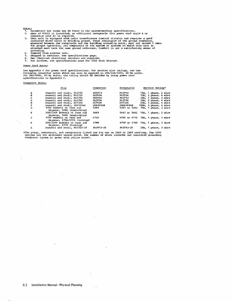
Notes: ~arameters not shown may be found in the system/machine specifications. 2. When SF #3622 is installed. an additional receptacle (for power cord style A or
connector note A) is required. 3. This unit is equipped with radio interference control circuits and requires a good
insulated wired earth or building ground. Total resistance of the ground conductor. measured between the receptacle and the building groundi ng point. must not exceed 3 obus. For proper operation. all components of the system or systems to which this unit is attached must have the. same ground reference. Conduit is not a satisfactory means of grounding.
4. Powered from another unit. 5. Shipped in sections. See specifications page. 6. TWO identical electrical services are required. 7. For airflow. see specifications page for 2302 Disk Storage.
Power Cord Notes:
see Appendix C for power cord specifications. For service size ratings. see the following connector notes which can also be applied to 200/220/235V. 50-Hz units. For 380/408V. 50-Hz units. the rating should be decided by using power cord specifications in Appendix C.
Connector Notes:
Plug COnnector Receptacle Service Rating*
A Russell and Stoll. FS3720 FS3913 FS3743 15A. 1 phase. 3 B !<ussell and Stoll. FS3730 FS3914 FS3744 15A. 3 phase. 4 C Russell and Stoll. FS3750 FS3933 FS3753 30A. 1 phase. 3 D Russell and Stoll. FS3760 FS3934 FS3754 30A. 3 phase. 4 E Russell and Stoll. SC7328 SC742S SC7324 60A. 3 phase. 4 F Russell and Stoll. JPS1034H JCS1034H JRSR1034H 100A. 3 phase, 4 G 115V Hubbell or Pass and 5269 5261 or 5262 15A. 1 phase. 3
seymour, 5266 {nonlocking> H 20S/230V Huboell or Pass and 5669 5661 or 5662 15A. phase. 3
seymour. 5666 (nonlocking) J 115V Huhbell or Pass and 4730 4700 or 4710 15A. phase.
seymour. 4720/4723 {locking> K 20S/230V Hubbell or Pass and 47S0 4150 or 4160 15A. phase,
seymour. 4770 (locking) L Russell and Stoll. FS3720-20 FS3913-20 FS3743-20 20A. phase.
*The plugs. connectors. and receptacles listed are for use on 20SV or 230V services. The 115V options are not available unless noted. ~I'he number of wires includes one insulated grounding conductor (green or green with yellow trace).
E.2 Installation Manual-Physical Planning
3
3
3
wire wire wire wire wire wire wire
wire
wire
wire
wire

T Ii U i
T
Type
360 360 360
360 360 360
360 360 360
360 360 360
360 360 360
360 360 360
360 360 360
360 360 360
360 Ii U s 360
S T
\iT U Ii
360
360 360 360
360 360 360
1051 1231 1285
11104 1412 1418
1418 1428 1428
111115 2167 2302
2302 2361 2361
2365 2365 2365
2365 2385 2385
2846 3060 3080
3085 3086
, 1112
Model
22 25 30
40D-G 40GF,B 114E,F
44G 44B 50F,G
50B 50BG 50I
65B,I 65IB,J 65I
65IB 65J 61
75B,I 75IB,J 85
85 85 85
85 85 195J
195K 195KJ 195L
195 195 195
l,N 1 Nl 1
2 1 1,3
2 1,3 2
Nl 1-4 3
4 1 2
2,3 5 12
13 1 2
1 1 1-3
1 1 3
Descri pti on kVA
2022 Processing Unit 2,4 2025 Processing Unit 7,11 2030 Processing Unit 3,8
2040 Processing Unit 2,5 20110 Processing Unit 3,7 2044 Processing Unit 5,3
2044 Processing Unit 6,5 2044 Processing Unit 9,5 2050 Processing Unit 6,5
2050. Processing Unit 6,8 2050 Processing Unit 7,0 2050 Processing Unit 7,6
2065 Processing Unit 5,11 2065 Processing Unit 5,11 Multiprocessing Unit 5,11
Multiprocessing Unit 5,11 Multiprocessing Unit 5,11 2061 Processing Unit 6,85
2075 Processing Unit 2075 Processing Unit 2085 Processing unit
Power Oist Unit (2085) MG Starter (Remote) MG Starter (Remote)
MG (Remote) KG (Remote) 3195 Proc Unit , Stg
3195 Proc Unit , Stg 3195 Proc Unit , Stg 3195 Proc Unit , Stg
MG (Remote) KG (Remote) Rotary Cony (Remote)
Control Unit 0,2 Optical Mark Page Rdr 1,2 Optical Reader 1,8
Printer 1,5 Magnetic Character Rdr 3,39 Optical Character Rdr 4,6
Optical Character Rdr 4,6 Alphameric Optical Rdr 11,6 Alphameric Optical Rdr 4,6
Printer 1,1 Configuration Unit 0,65 Oisk Storage 9,0
Oisk Storage 12,6 Core storage 4,5 Core Storage 7,0
Processor Storage 7,11 Processor Storage 4,0 Processor storage 8,5
Processor Storage 7,11 Processor storage Processor storage
Channel Controller 0,88 system Console Power Unit
Power Oist Unit Coolant Oist Unit Audio Response Unit 2,0
Appendix F. System/360 Specification Summary (Metric Units)
Electrical Environmental Notes
Service (Listed Dimensions Clearances at End
Pwr m
3/
(cm) (cm) of Table) Cord Conn Weight Style Note kcal/hr min (kg) Front Side Height F R Rt L
03 B 1.150 26 690 152 1,2 E- E 5.200 23 930 152 1,2 03 B 2.550 26 780 152 1-3
Bl 0 1.800 9 180 152 1-3 Bl 0 2.650 9 1.050 178 1-3 El 0 3.800 46 1.350 183 1-3
El 0 4.800 46 1.350 183 1-3 El (7) 0(2) 7.100 68 1.950 183 1-3,6 E3 E 5.150 61 2.150 184 1,2
~
E3 E 5.400 85 2.450 1811 1-3 E3 E 6.050 140 3.250 184 1-3 E3 E 6.350 1110 3.250 184 1-3
El E 4.000 60 1.950 1811 1,2 El E 4.000 60 2.400 184 1,2 El E 4.000 60 3.750 184 1,2
El E 4.000 60 3.900 184 1,2 El E 4.000 60 4.050 184 1,2 El E 5.050 140 1.700 184 1,2
E3 E 7.000 95 2.350 184 1-3 E3 E 7.000 95 2.450 184 1-3 03 0 88 6.550 198 1-3
0 690 16 152 118 91 91 16 16 1-3 76 76 0 0 1 16 16 0 0 1
25.150 2.100 254 86 135 16 76 76 16 1 1.950 218 86 135 16 76 76 16 1
140 6.150 118 1-3
220 8.550 178 1-3 300 11.300 118 1-3 380 12.900 178 1-3
14.000 1.650 206 91 130 .16 16 16 16 1 10.100 1.400 193 94 137 16 76 76 76 1 5.800 710 142 91 94 16 76 76 16 1
AS A 110 0 89 66 38 69 0 91 0 76 Al A 9110 9 290 110 61 1t4 107 107 16 91 3 01 0 1.300 17 730 181 91 152 91 122 107 122
960 8 130 170 81 136 91 91 122 101 4 01 C 2.050 10 1.150 284 105 153 107 122 91 91 5 01 0 2.650 17 1.250 284 105 153 101 122 91 91 5
01 0 2.650 17 1.250 284 105 153 101 122 91 91 5 01 0 2.650 17 1.250 284 105 153 107 122 91 91 5 01 0 2.650 17 1.300 2811 105 153 101 122 91 91 5
Al A 810 2 380 142 109 117 91 91 122 16 A2 A 510 15 270 117 1 E- E 5.050 63 1.850 217 84 175 152 152 152 152 3-5,7
E- E 7.100 63 2.050 217 84 115 152 152 152 152 3-5,7 E3 E 2.800 35 970 229 81 179 183 16 76 91 3 E3 E 11.400 35 9'70 229 81 179 183 16 16 91 3
E3 E 6.400 43 1.250 184 1 3.800 22 1.150 75 .213 184 16 76 1,4
E3 E 7.350 67 1.500 184 1
E3 E 6.400 43 1.250 184 1 220 198 1 420 198 1
A2 A 660 26 910 184 16 122 183 140 1 3.550 32 1.150 170 76 61 91 101 1,3,4
0 590 88 81 152 91 1,3,11
0 460 81 81 152 91 0 91 91 1,3 0 660 159 81 178 91 91 91 0 1,3
A3 A 1.300 51 280 95 80 178 107 91 76 16
System/360 Specification Summary (Metric Units) F.1

Notes: ~arameters not shown may be found in the system/machine specifications. 2. When SF #3622 is installed. an additional receptacle (for power cord style A or
connector note A) is required. 3. This unit is equipped with radio interference control circuits and requires a good
insulated wired earth or building ground. Total resistance of the ground conductor. measured between the receptacle and the building grounding point. must not exceed 3 ohms. For proper operation. all components of the system or systems to which this unit is attached must have the same ground reference. Conduit is not a sat~sfactory means of grounding.
4. Powered from another unit. 5. Shipped in sections. see specifications page. 6. TWo identical electrical services are required. 7. For airflow. see specifications page for 2302 Disk Storage.
Power Cord Notes:
See Appendix C for power cord specifications. For service size ratings. see the following connector notes which can also be applied to 200/220/235V. 50-Hz units. For 380/408V. 50-Hz units. the rating should be decided by using power cord specifications in Appendix C.
Connector Notes: Plug Connector Receptacle service Rating:*
A Russell and Stoll. FS3720 FS3913 FS3743 15A. 1 phase. 3 wire B' Russell and Stoll. FS3730 FS3914 FS3744 15A. 3 phase. 4 wire C Russell and Stoll. FS3750 FS3933 FS3753 30A. 1 phase. 3 wire D Russell and Stoll. FS3760 FS3934 FS3754 30A. 3 phase. 4 wire E Russell and Stoll. SC7328 SC7428 SC7324 60A. 3 phase. 4 wire F Russell and Stoll, JPs1034H JCS1034H JRSR1034H 100A. 3 phase. 4 wire G 115V Hubbell or Pass and seymour. 5269 5261 or 5262 15A. 1 phase. 3 wire
5266 ( nonlocking) H 208/230V Hubbell or Pass and 5669 5661 or 5662 15A. phase. 3 wire
Seymour, 5666 (nonlocking) J 115V Hubbell or Pass and seymour, 4730 4700 or 4710 15A. phase. 3 wire
4720/4723 (locking) K 208/230V Hubbell or Pass and 4780 4750 or 4160 15A. phase. 3 wire
Seymour, 4770 (locking) L Russell and Stoll. FS3720-20 FS3913-20 FS3143-20 20A. phase. 3 wire
*The plugs. connectors, and receptacles listed are for use on 208V or 230V services. The 115V options are not available unless noted. The number of wires includes one insulated grounding conductor (green or green with yellow trace).
F.2 Installation Manual-Physical Planning

Appendix G. Inch-to-Centimeter Conversion Table in. em in. em in. em in. em in. em in. em in. em in. em
1/8 0,318 48 122 98 249 148 376 198 503 248 630 298 757 348 884
1/4 0,635 48-1/2 123 98-1/2 250 148-1/2 377 198-1/2 504 248-1/2 631 298-1/2 758 348-1/2 885 3/8 0,953 49 124 99 251 149 378 199 505 249 632 299 759 349 886
1/2 1,270 49-1/2 126 99-1/2 253 149-1/2 380 199-1/2 507 249-1/2 634 299-1/2 761 349-1/2 888 5/8 1,588 50 127 100 254 150 381 200 508 250 635 300 762 350 889 3/4 1,905 50-1/2 128 100-1/2 255 150-1/2 382 200-1/2 509 250-1/2 636 300-1/2 763 350-1/2 890
7/8 2,223 51 130 101 257 151 384 201 511 251 638 301 765 351 892
1 2,540 51-1/2 131 101-1/2 258 151-1/2 385 201-1/2 512 251-1/2 639 301-1/2 766 351-1/2 893
1-1/2 4 52 132 102 259 152 386 202 513 252 640 302 767 352 894
2 5 52-1/2 133 102-1/2 260 152-1/2 387 202-1/2 514 252-1/2 641 302-1/2 768 352-1/2 895
2-1/2 6 53 135 103 262 153 389 203 516 253 643 303 770 353 897
3 8 53-1/2 136 103-1/2 263 153-1/2 390 203-1/2 517 253-1/2 644 303-1/2 771 353-1/2 898
3-1/2 9 54 137 104 264 154 391 204 518 254 645 304 772 354 899
4 10 54-1/2 138 104-1/2 265 154-1/2 392 204-1/2 519 254-1/2 646 304-1/2 773 354-1/2 900
4-1/2 11 55 140 105 267 155 394 205 521 255 648 305 775 355 902
5 13 55-1/2 141 105-1/2 268 155-1/2 395 205-1/2 522 255-1/2 649 305-1/2 776 355-1/2 903
5-1/2 14 56 ' 142 106 269 156 396 206 523 256 650 306 m 356 904
6 15 56-1/2 144 106-1/2 271 156-1/2 398 206-1/2 525 256-1/2 652 306-1/2 779 356-1/2 906
6-1/2 17 57 145 107 272 157 399 207 526 257 653 307 780 357 907
7 18 57-1/2 146 107-1/2 273 157-1/2 400 207-1/2 527 257-1/2 654 307-1/2 781 357-1/2 908
7-1/2 19 58 147 108 274 158 401 208 528 258 655 308 782 358 909
8 20 58-1/2 149 108-1/2 276 158-1/2 403 208-1/2 530 258-1/2 657 308-1/2 784 358-1/2 911
8-1/2 22 59 150 109 277 159 404 209 531 259 658 309 785 359 912
9 23 59-1/2 151 109-1/2 278 159-1/2 405 209-1/2 532 259-1/2 659 309-1/2 786 359-1/2 913
9-1/2 24 60 152 110 279 160 406 210 533 260 660 310 787 360 914
10 25 60-1/2 154 110-1/2 281 160-1/2 408 210-1/2 535 26'0-1/2 662 310-1/2 789 360-1/2 916
10-1/2 27 61 155 111 282 161 409 211 536 261 663 311 790 361 917
11 28 61-1/2 156 111 ~1/2 283 161-1/2 410 211-1/2 537 261-1/2 664 311-1/2 791 361-1/2 918
11-1/2 29 62 . 157 112 284 162 411 212 538 262 665 312 792 362 919
If 30 62-1/2 159 112-1/2 286 162-1/2 413 212-1/2 540 262-1/2 667 312-1/2 794 362-1/2 921
12-1/2 32 63 160 113 287 163 414 213 541 263 6.68 313 795 363 922
13 33 63-1/2 161 113-1/2 288 163-1/2 415 213-1/2 542 263-1/2 669 313-1/2 796 363-1/2 923
13-1/2 34 64 163 114 290 164 417 214 544 264 671 314 798 364 925
14 36 64-1/2 164 114-1/2 291 164-1/2 418 214-1/2 545 264-1/2 672 314-1/2 799 364-1/2 926
14-1/2 37 65 165 115 ,292 165 419 215 546 265 673 315 800 365 927
15 38 65-1/2 166 115-1/2 293 165-1/2 420 215-1/2 547 265-1/2 674 315-1/2 801 365-1/2 928
15-1/2 39 66 168 116 295 166 422 216 549 266 676 316 803 366 930
16 41 66-1/2 169 116-1/2 296 166-1/2 423 216-1/2 550 266-1/2 677 316-1/2 804 366-1/2 931
16-1/2 42 67 170 117 297 167 424 217 551 267 678 317 805 367 932
17 43 67-1/2 171 117-1/2 298 167-1/2 425 217-1/2 552 267-1/2 679 317-1/2 806 367-1/2 933
17-1/2 44 68 173 118 300 168 427 218 554 268 681 318 808 368 935
18 46 68-1/2 174 118-1/2 301 168-1/2 428 218-1/2 555 268-1/2 682 318-1/2 809 368-1/2 936
18-1/2 47 69 175 119 302 169 429 219 556 269 683 319 810 369 937
19 48 69-1/2 177 119-1/2 304 169-1/2 431 219-1/2 558 269-1/2 685 319-1/2 812 369-1/2 939
19-1/2 50 70 178 120 305 170 432 220 559 270 686 320 813 370 940
20 51 70-1/2 179 120-1/2 306 170-1/2 433 220-1/2 560 270-1/2 687 320-1/2 814 370-1/2 941
20-1/2 52 71 180 121 307 171 434 221 561 271 688 321 815 371 942
21 53 71-1/2 182 121-1/2 309 171-1/2 436 221-1/2 563 271-1/2 690 321-1/2 817 371-1/2 944
21-1/2 55 72 183 122 310 172 437 222 564 272 691 322 818 372 945
22 56 72-1/2 184 122-1/2 311 172-1/2 438 222-1/2 565 272-1/2 692 322-1/2 819 372-1/2 946
22-1/2 57 73 185 123 312 173 439 223 566 273 693 323 820 373 947
23 58 73-1/2 187 123-1/2 314 173-1/2 441 223-1/2 568 273-1/2 695 323-1/2 822 373-1/2 949
23-1/2 60 74 188 124 315 174 442 224 569 274 696 324 823 374 950
24 61 74-1/2 189 124-1/2 316 174-1/2 443 224-1/2 570 274-1/2 697 324-1/2 824 374-1/2 951
24-1/2 62 75 191 125 318 175 444 225 572 275 699 325 826 375 953
25 64 75-1/2 192 125-1/2 319 175-1/2 446 225-1/2 573 275-1/2 700 325-1/2 827 375-1/2 954
25-1/2 65 76 193 126 320 176 447 226 574 276 701 326 828 376 955
26 66 76-1/2 194 126-1/2 321 176-1/2 448 226-1/2 575 276-1/2 702 326-1/2 829 376-1/2 956
26-1/2 67 77 196 127 323 177 450 227 577 277 704 327 831 377 958
27 69 77-1/2 197 127-1/2 324 177-1/2 451 227-1/2 578 277-1/2 705 327-1/2 832 377-1/2 959
27-1/2 70 78 198, 128 325 178 452 228 579 278 706 328 833 378 960
28 71 78-1/2 199 128-1/2 326 178-1/2 453 228-1/2 580 278-1/2 707 328-1/2 834 378-1/2 961
28-1/2 72 79 201 129 328 179 455 229 582 279 709 329 836 379 963
29 74 79-1/2 202 129-1/2 329 179-1/2 456 229-1/2 583 279-1/2 710 329-1/2 837 379-1/2 964
29-1/2 75 80 203 130 330 180 457 230 584 280 711 330 838 380 965
-30 76 80-1/2 204 130-1/2 331 180-1/2 458 230-1/2 585 280-1/2 712 330-1/2 839 380-1/2 966
30-1/2 77 81 206 131 333 181 460 231 587 281 714 331 841 381 968
31 79 81-1/2 207 131-1/2 334 181-m 461 231-1/2 588 281-1/2 715 331-1/2 842 381-1/2 969
31-1/2 80 82 208 132 335 182 462 232 589 282 716 332 843 382 970
32 81 82-1/2 210 132-1/2 337 182-1/2 464 232-1/2 591 282-1/2 718 332-1/2 845 382-1/2 972
32-1/2 83 83 211 133 338 183 465 233 592 283 719 333 B46 383 973
33 84 83-1/2 212 133-1/2 339 183-1/2 466 233-1/2 593 283-1/2 720 333-1/2 847 383-1/2 974
33-1/2 85 84 213 134 340 184 467 234 594 284 721 334 848 384 975
34 86 84-1/2 215 134-1/2 342 184-1/2 469 234-1/2 596 284-1/2 723 334-1/2 850 384-1/2 977
34-1/2 88 85 216 135 343 185 470 235 597 285 724 335 851 385 978
35 89 85-1/2 217 135-1/2 344 185-1/2 471 235-1/2 598 285-1/2 725 335-1/2 852 385-1/2 979
35-1/2 90 86 218 136 345 186 472 236 599 286 726 336 853 386 980
36 91 86-1/2 220 136-1/2 347 186-1/2 474 236-1/2 601 286-1/2 728 336-1/2 855 386-1/2 982
j{,-1/2 93 87 221 137 348 187 475 237 602 287 729 337 856 387 983
37 94 87-1/2 222 137-1/2 349 187-1/2 476 237-1/2 603 287-1/2 730 337-1/2 857 387-1/2 984
37-1/2 95 88 224 138 351 188 478 238 605 288 732 338 859 388 9B6
38 97 8B-1/2 225 13B-l/2 352 188-1/2 479 238-1/2 606 288-1/2 733 338-1/2 860 388-1/2 987
38-1/2 98 89 226 139 353 189 480 239 607 289 734 339 861 389 988
39 99 89-1/2 227 139-1/2 354 189-1/2 481 239-1/2 608 289-1/2 735 339-1/2 862 389-1/2 989
39-1/2 100 90 229 140 356 190 483 240 610 290 737 340 864 390 991
40 102 90-1/2 230 140-1/2 357 190-1/2 484 240-1/2 611 290-1/2 738 340-1/2 865 390-1/2 992
40-1/2 103 91 231 141 358 191 485 241 612 291 739 341 866 391 993
41 104 91-1/2 232 141-1/2 359 191-1/2 486 241-1/2 613 291-1/2 740 341-1/2 867 391-1/2 994
41-1/2 105 92 234 142 361 192 488 242 615 292 742 342 869 392 996
42 107 92-1/2 235 142-1/2 362 192-1/2 489 242-1/2 616 292-1/2 743 342-1/2 870 392-1/2 997
42-1/2 108 93 236 143 363 193 490 243 617 293 744 343 871 393 998
43 109 93-1/2 237 143-1/2 364 193-1/2 491 243-1/2 618 293-1/2 745 343-1/2 872 393-1/2 999
43-1/2 110 94 239 144 366 194 493 244 620 294 747 344 874 394 1.001
44 112 94-1/2 240 144-1/2 367 194-1/2 494 244-1/2 621 294-1/2 748 344-1/2 875 394-1/2 1.002
44-1/2 113 95 241 145 368 195 495 245 622 295 749 345 876 395 1.003
45 114 95-1/2 243 145-1/2 370 195-1/2 497 245-1/2 624 295-1/2 751 345-1/2 878 395-1/2 1.005
45-1/2 116 96 244 146 371 196 498 246 625 296 752 346 879 396 1.006
46 117 96-1/2 245 146-1/2 372 196-1/2 499 246-1/2 626 296-1/2 753 346-1/2 880 396-1/2 1.007
46-1/2 118 97 246 147 373 197 500 ' 247 627 297 754 347 881 397 1.008
47 119 97-1/2 248 147-1/2 375 197-1/2 502 247-1/2 629 297-1/2 756 347-1/2 883 397-1/2 1.010
47-1/2 121 Inch-to-Centimeter Conversion Table G.1
abbreviations 1.22 acoustical treatment 1.4 air
conditioning 1.1,1.7, 1.9 distribution systems 1.9 filtration 1.8
auflow (see specifications for each system}machille) AWG number for power cord wire C.I
Basic Storage Module (BSM) Analyzer cabling to System/360 -Model &5
CPU schematic 2085.8 cabling to System/360 Model 195
coolant hose schematic 3195.14 CPU schematic 3195.10
plan view 1.19 specifications 1.18
b'uilding requirements 1.2
cable A WG number for power cord wire C.l delivery schedule 1.1 length limitations (appear in cabling schematics, or speciflQtious
where applicable) ordering information 1.1, 1.17 power cord description by style C.l power cord style (see specifications for each system/machine) schematics (see schematic for each system/machine)
cable group reference 30-02 to 30-10 2030.2 32-31 to 32-33 2022.2 40-01 to 40-08 2040.2 44-01 to 44-08 2044.2 50-01 to 50-04 2050.5 50-06 to 50-12 2050.5 60-03 2065.12,2065.14 60-04 to 60-05 2065.12 60-06 2065.12,2065.14,2067.8 60-08 2065.12,2065.14,2067.8,2067.9 60-09 2065.12,2065.14 60-10 to 60-11 2065.12,2065.14,2067.8,2067.9 60-12 2065.12 60-13 2065.12,2065.14 60-14 to 60-15 2065.12,2065.14,2067.8,2067.9 60-16 2065.12,2065.14,2067.8 60-17 to 60-19 2065.12,2065.14 60-20 2065.12,2065.14,2067.8 60-22 to 60-23 2065.12,2065.14,2067.9 60-25 2065.12,2065.14,2067.8 60-27 2065.12,2065.14 60-28 2065.12,2065.14,2067.8,2067.9 60-29 2065.12,2065.14,2067.8 60-30 2065.12,2065.14 60-31 to 60-33 2065.12 60-34 2065.12,2065.14,2067.8 60-35 2065.12,2065.14 60-42 to 60-57 2065.16 67 -02 to 67 -09 2067.9 67-10 to 67-11 2067.8 67-12 2067.9 67-14 to 67-19 2067.9 67-20 to 67-22 2067.8,2067.10
cable group reference (continued)
67-23 to 67-25 2067.10 67-27 to 67-28 2067.10 67-31 to 67-32 2067.to 67-35 2067.8,2067.10 67-36 to 67-38 2067.8 67-98 2067.10 70-01 to 70-15 2075.6 70-17 to 70-27 2075.6 85-01 to 85-45 2085.9 8546 to 85-51 2085.10 85-52 2085.9 95-01 to 95-04 3195.15 95-09 to 95-38 3195.10 9540 to 95-54 3195.11 95-60 to 95-63 3195.11 95..65 to 95-68 3195.11 95-70 to 95-71 3195.11 95-72 to 95-78 3195.13 95-80 to 95-84 3195.13 95-86 to 95-97 3195.13 443 2025.3,2025.6 446 to 447 2025.3~ 2025.6 503 2025.8 504 to 505 2025.4,2025.7
> 510 2025.5 604 2025.5,2025.8 605 to 606 2025.8 611 to 612 2025.5 630 2025.4,2025.7 631 2025.8 632 2025.7 633 2025.5 634 2025.4 650 to 655- 7772.2 702 4.5 706 to 708 4.5 712t0717 4.5 720 4.5 722 to 723 4.5 735 4.5 746 4.5 747 to 748 4.3,4.5 754 to 755 4.5 765 4.3 776 to 777 875 to 880 1376 to 1379 3501 to 3502
4.3 2167.2
4.4 2025.4,2025.7
3503 2025.7 3504 2025.4 3505 2025.4, 2025.7 3506 2025.7 3507 2025.4 3508 2025.4,2025.7 3510 to 3513 2025.4,2025.7 3516 to 3518 2025.4,2025.7 3519 2025.7 3520 to 3522 2025.4,2025.7 3523 2025.7 3524 2025.4 3526 2025.4, 2025.7
Index
Index X.l
caNe group reference (continued)
3527 2025.4 cables
from non~IBM devices (see cabling s'chertratkfor e1l:ch system/machine)
requested for other reasons 1.17 supplied 1.17
ca,bling schematics (see schematic for eachsystem!machine) ~E room and test area 1.18 channel-to-channel adapter (SF #1850) cabling 4.2 circuit breakers 1.10 clearances, service (see specifications for each system/machine) computer area
data storage 1.13, 1.15 emergency operation 1.14 environment limits 1.21, A.1 location 1.13 safety and fire considerations 1.13
connector manufacturers 1.21 control-to-channel cabling, general 4.1 convenience outlets 1.11 conversion table, inch-to-centimeter G.1 converter, rotary (for System/360 Model 195) 3195.9 Customer Engineering room, layout and power 1.18 customer-supplied chilled water
requirements A.1 specifications A.1 typical connections for A.2
Data Adapter Unit (FE DAU) data cell storage and shipping definitions 1.22
1.18,4.4 1.15
dimensions (see specifications for each system/machine) direct control cabling 4.3 disk pack storage and shipping 1.15 distribution guide for motor-generator output to
3085 PDU 3195.5,3195.7
environmental conditions (see specifications for each system/machine)
environmental limitations, shipping 1.21
Field Engineering test equipment cabling 4.4 filtration, air 1.8 fire and safety precautions' 1.13 fire extinguishers 1.13 floor construction 1.3
illustration 1.4 furniture and fixtures (CE room) 1.18
general control-to-channel cabling 4.1 grounding 1.11 grounding requirements, special (appear in specification summary-'
where applicable) group number, cable (see cable group reference)
heat output (see specifications for each system/machine) humidity (see temperature and humidity)
inch-to-centimeter conversion table G.1 input/output device priority considerations B.l input/output priority sequence - 1.16
X.2 System/360 Installation Manual-Physical Planning
layout 'Of system 1.2 lighting considerations 1.6 lightning protection 1.11 liquid coolant system A.1
machine operating limits 1.7.1.21 machine specifications (see specificationsforellch machine)
standard symbols used in 1.20 magnetic tape storage and shipping 1.15 manufacturers of plugs, receptacles, and connectors 1.21 metric conversions, rounding of 1.21 motor-generator (remote) specifications for
System/360 Model 85 50-Hz input 2085.6 60-Hz input 2085.7
System/360 Model 195 50-Hz input 3195.5 60-Hz input 3195.7
motor-generator starter (remote) specifications for System/360 Model 85
50-Hz input 2085.4 60-Hz input 2085.5
, operating limits, machine environment 1.7, 1.21 output priority sequence 1.16
personnel training, suggested 1.14 phase rotation, system power 1.11 plan views (see specifications for each system/machine) planning, preinstallation 1.1 plug installation C.1 plug manufacturers 1.21 power cord length 1.10 power cord style specifications C.1 power distribution system 1.10, 1.12 power requirements 1.10
CE room 1.18 convenience outlets 1.11 emergency controls 1.11 grounding 1.11 installation 1.10 lightning protection 1.11 phase rotation 1.11 plugs and connectors (see specifications for each
system/machine) , power cord style (see specifications for each system/machine) problem areas 1.11
precautions, fire and safety 1.13 preinstallation planning 1.1 priority, I/O device
assignment 1.16 considerations (table) B.1
raised floor illustrations 1.4 objectives 1.3, 1.4 safety notes 1.3, 1.4
receptacle manufacturers 1.21 recording instruments, temperature and humidity 1.8 requirements, installation
acoustics 1.4 air conditioning 1.7

requirements, installation (continued)
building 1.2 furniture
CE room 1.18 illustration 1.19 precautions 1.4
lighting 1.6 magnetic tape, disk, and data cell storage 1.15 Model 85-additional A.1 Model 195-additional _ A.1 personnel training 1.14 power 1.10 preinstallation planning 1.1 RETAIN/370 services (FE DAU) 1.18 safety and fire precautions 1.13 safety and security 1.13 sched uling 1.1 service clearances (see specifications for each system/machine) shipping, environmental1imitations 1.21 space and layout requirements 1.2 sprinkler systems 1.13 teleprocessing 1.3 temperature and humidity 1.7
rotary converter (remote) for System/360 Model 195 (World Trade only) 3195.9
rounding of metric conversions 1.21
safety and fire precautions 1.13 scheduling 1.1 service clearances (see specifications for each system/machine) shipping, environmental limitations 1.21 space and layout requirements 1.2 special grounding requirements (appear in specification summary
where applicable) specification summary
English units E.1 metric units F.1
sprinkler systems 1.13 standard environmental specifications 1.21 standard symbols used in system/machine specifications
(illustration) 1.20 static charge prevention 1.4 storage considerations
disk and data cell 1.15 general data 1.13, 1.15 magnetic tape 1.15
system layout 1.2 system specifications (see specifications for each system)
standard symbols used in 1.20 symbols and specifications 1.20, 1.21 System/360 and System/370 Field Engineering Furniture and
Test Equipment 1.19 System/360 Model 22
cabling schematic 2022.2 2022 Processing Unit specifications 2022.1
System/360 Model 25 cables from non-IBM devices
World Trade 2025.5 U.S. 2025.8
cabling schematic World Trade 2025.3 U.S. 2025.6
2025 Processing Unit specifications 2025.2 System/360 Model 30
cabling schematic 2030.2 2030 Processing Unit specifications 2030.1
System/360 Model 40 cabling schematic 2040.2 2040 Processing Unit specifications 2040.1
System/360 Model 44 cabling schematic 2044.2 2044 Processing Unit specifications 2044.1
System/360 Model 50 cabling schematic 2050.5 2050 Processing Unit specifications
Models F, G, and H 2050.2 Models HG and I 2050.4
System/360 Model 65 cabling schematic
Model 65 J Multiprocessing with additional storage 2065.15 multiprocessing 2065.13 single processor 2065.11
specifica tions Multiprocessing Unit, Model I 2065.6 Multiprocessing Unit, Model IH 2065.8 Multiprocessing Unit, Model J 2065.10 2065 Processing Unit, Models H and I 2065.2 2065 Processing Unit, Models IH and J 2065.4
System/360 Model 67 cabling schematic
Model 67-1 2067.7 Mode167-2 2067.9
configuration rules 2067.1 configurations with
2067 Modell 2067.2 2067 Model 2 2067.3
2067 Processing Unit specifications 2067.6 System/360 Model 75
cabling schematic 2075.5 2075 Processing Unit specifications
Models H and I 2075.2 Models IH and J 2075.4
System/360 Model 85 additional cooling requirements for A.l cabling for 2880 2085.10 cabling schematic 2085.8 memory (storage) bus coupler 2085.13 specifications
coolant distribution unit (2085 and 2385) A.2 motor generator (remote)
SO-Hz input 2085.6 60-Hz input 2085.7
motor-generator starter (remote) 50-Hz input 2085.4 60-Hz input 2085.5
power distribution unit (2085 frame 14) 2085.3 2085 Processing Unit 2085.2
System/360 Model 195 (see also 3060, 3080, 3085, and 3086) additional cooling requirements for' A.1 cabling schematic
channels 3195.12 coolant hoses 3195.14 CPU 3195.10
specifica tions motor generator (remote) for
50-Hz input 3195.5 60-Hz input 3195.7
rotary converter (remote) (World Trade only) 3195.9 3195 Processing Unit and storage
Models J andK 3195.2 Models KJ and L 3195.4
Index X.3

teleprocessing 1.3 temperature and humidity (see specifications for each
system/machine) maximum 1.7 recommended design conditions 1.7 recording instruments 1.8
templates FE furniture (iIlustra tion) 1.19 order (form) numbers 0.1 usage in machine layout 1.3
termination hardware, cables from non-IBM devices (see cabling schematic·for each system/machine)
test area requirements 1.18
units with integral or abutted controls 4.5
vibration in office environment, effect on machines 1.6
water, ~ustomer·suppIied chilled requirements A.I specifications A.l typical connections for A.2
weight (see specifications for each system/machine)
1051 Control Unit Models 1 and N 1 specifications 1051 1231 Optical Mark Page Reader Model N1
cable groups 4.5 priority considerations B.1 specifications 1231
1285 Optical Reader Modell cable groups 4.5 priority considerations B.l specifications 1285
1404 Printer Model 2 specifications 1404 to 2821 cabling (see System/370 Installation Manual
Physical Planning) 1412 Magnetic Character Reader Modell
cable groups 4.5 priority considerations B.1 specifications 1412.2
1418 Optical Character Reader Models 1 to 3 cable groups 4.5 priority considerations B.l specifications 1418.2
1428 Alphameric Optical Reader Models 1 to 3 cable groups 4.5 priority considerations B.l
. specifications 1418.2 1445 Printer Model Nl
cable groups 4.5 priority considerations B.1 specifications 1445
2022 Processing Unit (see System/360 Model 22) 2025 Processing Unit (see System/360 Model 25) 2030 Processing Unit (see System/360 Model 30) 2040 Processing Unit (see System/360 Model 40) 2044 Processing Unit (see System/360 Model 44) 2050 Processing Unit (see System/360 Model 50) 2065 Processing Unit (see System/360 Model 65)
X.4 System/360 Installation Manual-Physical Pla1;1ning
2067 Processing Unit (see System/360 Model 67) 2075 Processing Unit (see System/360 Model 75) 2085 Processing Unit (see System/360 Model 85) 2167 Configuration Unit Models 1 to 4
. cabling schematic 2167.2 specifications 2167.1
2302 Disk Storage Models 3 and 4 specifications 2302.2 to 2841 cabling (see System/370 Installation Manual~
Physical Planning) 2361 Core Storage Models 1 and 2
cabling to System/360 Model 50 2050.5 to System/360 Model 65 2065.11
. to System/360 Model 75 2075.5 specifications 2361
2365 Processor Storage cabling
Model 2 to System/360 Model 65 2065.13 Model 2 to System/360 Model 67-1 2067.7 Model 3 to System/360 Model 75' 2075.5 Model 5 to System/360 Model 85 2085.8 Model 12 to System/360 Model 67-2 2067.9 Model 13 to System360 Model 65 Multiprocessing
2365.13,2365.15 specifications
Model 2 and 3 2365.1 Model 5 2365.2 Model 12 2365.3 Model 13 2365.4
2385 Processor Storage Models 1 and 2 to System/360 Model 85 cabling 2085.8 specifications
Modell Model 2
2385.2 2385.4
2846 Channel Controller Model 1 specifications 2846 to System/360 Model 67-2 cabling 2067.19
2955 Field Engineering Data Adapter Unit (FE DAU) cabling schematic 4.4 plan view 1.19 priority considerations B.1
3060 System Console Modell cabling schematic (Model 195) 3195.10 specifications 3060.2'
3080 Power Unit Models 1 to 3 cabling schematic (Model 195) 3195.10 coolant hose schematic 3195.14 specifications 3080
3085 Power Distribution Unit (PDU) Modell cabling schematic (Model 195) 3195.10 specifications 3085
3086 Coolant Distribution Unit (CDU) Modell cabling schematic (Model 195) 3195.10 coolant hose schematic 3195.14 specifications 3086
3195 Processing Unit and Storage (see System/360 Model 195) 7772 Audio Response Unit Model 3
cables from non-IBM devices 7772.2 cabling schematic 7772.2 priority considerations B.l speCifications 7772.1

IBM System/360 Installation Manual-Physical Planning
Order No. GC22-6820-12
This manual is, part of a library that serves as -a reference source for systems analysts, programmers, and operators of IBM systems. This form may be used to communicate your views about this publication. They will be sent to the author's department for whatever review and action, if any, is deemed appropriate.
IBM shall have the nonexclusive right, in its discretion, to use and distribute all submitted information, in any form, for any and all purposes, without obligation of any kind to the submitter. Your interest is appreciated.
Note: Copies of IBM publications are not stocked at the location to which this form is addressed. Please direct any requests for copies of publications, or for assistance in using your IBM system, to your IBM representative or to the IBM ,branch office serving your locality.
Possible topics for comment are:
Clarity Accuracy Completeness Organization Coding Retrieval Legibility
If you wish a reply, give your name and mailing address:
What is your occupation? _____________ ---:-______________ _
Number of latest Newsletter associated with this pUblication: ___ ---,-------------
Thank you for your cooperation. No postage stamp necessary if mailed in the U.s.A. (Elsewhere, an IBM office or representative will be happy to forward your comments.)

GC22-6820-12
Reader's Comment Form
Fold
Business Reply Mail No postage stamp necessary if mailed in U.S.A.
Postage will be paid by:
I nternational Business Machines Corporation Department B98 P.O. Box 390 Poughkeepsie, New York 12602
Fold
Fold Fold
International Business Machines Corporation Data Processing Division 1133 Westchester Avenue, White Plains, New York 10604 (U.S.A. only)
IBM World Trade Corporation 821. United Nations Plaza, New York, New York 10017 (International)
I I t f t I I I f
l - ---;
f I
FIRST CLASS P·ERMIT NO. 419
POUGHKEEPSIE, N.Y.
1 1 I I I I I I
I
I
I I I
---------f

International Business Machines Corporation Data Processing Division 1133 Westchester Avenue, White Plains, New York 10604 (U.S.A. only)
IBM World Trade Corporation 821 United Nations Plaza, New York, New York 10017 (International)