Embed Size (px)
Citation preview
GC20606-1D2 //20606-D2
SIN
GLE
/ D
OU
BLE
NEE
DLE
MED
IUM
&
HEA
VY-D
UTY
WIT
H T
HRE
AD
CU
TTER
& B
ACK
TA
CK
INSTRUCTION BOOK // PARTS CATALOGUE

ADD: WANPING TOWN, WUJIANG CITY, JIANGSU
PROVINCE, CHINA
TEL: +86-512-63391278
FAX: +86-512-63391371
POST. CODE: 215223
Http://www.typicalwpchina.com
E-mail:[email protected]
TYPICAL SEWING MACHINE WANPING MACHINERY CO.,LTD.
Please don't adjust and repair the machine by non-professionals,except adjusting stitch.
Specifications subject to change without notice

1
2
1
A
B
★ 、 、 、 、 、 、、 、
.Optional gauge size:3.2 4 4.8 8 9.5 12.716 19 25.4mm
★ 、 、 、 、 、 、、 、
.Optional gauge size:3.2 4 4.8 8 9.5 12.716 19 25.4mm
2. Main specifications
ModelSpecifications
Medium and heavy dutyMedium and heavy duty
1800spm
9mm
8mm by hand, 13mm by knee8mm by hand, 13mm by knee
36mm
Large vertical hook with auto-lubricationLarge vertical hook with auto-lubrication
DP 17 Nm125-180DP 17 Nm125-180
6.4mm (standard)6.4mm (standard)
Auto lubrication (partial of manually oiling)Auto lubrication (partial of manually oiling)
Servo motor 550WServo motor 550W
GC20606-D2 GC20606-1-D2
The models adopt double (single) needle and two (single)vertical hooks with auto lubrication for thread looping,
sliding lever for thread take up to form two lines oflockstitch seam. The upper shaft and lower shaft aresupported by ball bearing and driven by teeth-typesynchronic belt; plunge oil pump lubrication system.They adopt the compound feed mechanism of feed dog,needle bar and presser foot, even if for long stitch lengthand long material. This series can deal with them freely.This series adopts numerical computerized controlsystem, which is designed with auto- t r imming,a u t o - s e t t i n g s t i t i c h l e n g t h , a u t o - b a c k t a c k i n g ,auto-presser foot lifter, etc. It is also designed with theelectrical servo motor.This series is widely used in the factories of suitcase,tent, cushion, leather, goods, apparel, mat, etc.
1. Brief Introduction
Application
Max.sewing speedMax.sewing speed
Max.stitch lengthMax.stitch length
Presser foot lift volumePresser foot lift volume
Needle bar strokeNeedle bar stroke
Rotating hookRotating hook
Needle
Needle gaugeNeedle gauge
Lubrication
Motor
3.1 Installation3.1.1 Location of the machineTo ensure a smooth running, the machine should be locatedon a rigid and flat floor. The insert of rubber mat betweenmachine stand and floor is recommended for further reducingthe running noise and vibration.
3.1.2 Installing the oil reservoir (Fig.1)Put the oil reservoir into the table cutout, and place the fourcushions on the four corners of the cutout, then set thecushions and oil reservoir in the table.
3.1.3 Installing the machine head (Fig.2)Set the hinge A onto the hinge socket B on the table, then turnthe machine head freely until it is seated on the frame of tablecutout
3. Installation and preparation

C
B
A
3
6
5
2
A
4
A
B
C
A
B
C
b a
3.1.4 Knee control presser foot lifter installation (Fig.3)a. InstallationInstall the Connector A, Bell crank B, Bell C in the ordershown in Fig.3.
B. Adjustment (Fig.4)1. When the presser foot is at its lowest position, keepthe crank in the position shown by b in the figure; turnthe knee control stop adjusting screw C to touch with theoil reservoir, and tighten the nut of screw C.2. When it is operated by knee, the presser foot liftvolume is controled by screw B. Turn the presser footdown, make the bell in the position shown in the figure,lift the presser foot to 13mm, adjust the screw B to touchwith the oil reservoir, then tighten the nut of screw B.
3.1.5 Installing the thread spool stand (Fig.5)Locate the thread spool stand at the right front of thetable, note that spool rest may not obstruct whenmachine head is turned backward, then tighten the nut A.
3.1.6 Installing the motor (Fig.6)Align the machine balance wheel belt groove A withmotor pulley belt groove B by moving the motor Cleftward and rightward. Be sure the belt is not touchwith table.

7
20 ~30A
B
C
D
E
F
G 10~12mm
3
9
10
8
E
D
A
B
C
D
Oil level mark
3.1.7 Connecting the clutch lever to the pedal (Fig.7)a. The optimum tilt angle of pedal with floor is 20~30degreee.b. Adjust the clutch of the motor so that clutch leverC and draw bar B run in line.c. The machine balance wheel should rotate counterclockwise for normal sewing when view from theopposite side of balance wheel G. The motor is rotatedin the same direction. The rotation canbe reversed byreversing the plug of motor (turn over 180 deg.).d. Adjust the tension of V-belt F by moving the motorvertically. The proper tension of V-belt is a slack of10-12mm when the belt is depressed at the belt pan byfinger.
3.1.8 Installing the bobbin winder (Fig.8)Align the pulley B of bobbin winder with outside ofbelt C and should be kept a proper clearance betweenthem, so that pulley B could be contacted with beltafter the stop latch thumb lever A depressed. Therebybelt drives the pulley B while machine running. Aftercheck bobbin winder is in parallel with belt slit E oftable, fastened by two wood screws D.
3.2 Preparation3.2.1 Cleaning the machineBefore delivery, the machine parts are coated withrust prevertive grease, which may be hardened andcontaminated by dust during storage and shipment.The grease must be removed by clean cloth withgasoline.
3.2.2 ExaminationThough every machine is confirmed by strictinspection and test before delivery, the machine partsmay be loosed or deformed after long distancetransportation after cleaning the machine. Turn thebalance wheel to see if there is running obstruction,parts collision, uneven ersistance or abnormal noise.If these exist, adjustment must be made accordinglybefore run.
3.2.3 Precautiona. Oiling (Fig.9)Oil amount should be filled according to the marks inthe oil reservoir. Mark H refers to the highest of oilamount; L refers to the lowest. Note that the oil levelshould not lower than Mark L. Otherwise, themachine parts can not be fed with oil and will causeoverheat and collision.Be sure to use machine oil HA-8 or HJ-7.
3.1.7 Connecting the clutch lever to the pedal (Fig.7)a. The optimum tilt angle of pedal with floor is 20~30degreee.b. Adjust the clutch of the motor so that clutch leverC and draw bar B run in line.c. The machine balance wheel should rotate counterclockwise for normal sewing when view from theopposite side of balance wheel G. The motor is rotatedin the same direction. The rotation canbe reversed byreversing the plug of motor (turn over 180 deg.).d. Adjust the tension of V-belt F by moving the motorvertically. The proper tension of V-belt is a slack of10-12mm when the belt is depressed at the belt pan byfinger.
3.1.8 Installing the bobbin winder (Fig.8)Align the pulley B of bobbin winder with outside ofbelt C and should be kept a proper clearance betweenthem, so that pulley B could be contacted with beltafter the stop latch thumb lever A depressed. Therebybelt drives the pulley B while machine running. Aftercheck bobbin winder is in parallel with belt slit E oftable, fastened by two wood screws D.
3.2 Preparation3.2.1 Cleaning the machineBefore delivery, the machine parts are coated withrust prevertive grease, which may be hardened andcontaminated by dust during storage and shipment.The grease must be removed by clean cloth withgasoline.
3.2.2 ExaminationThough every machine is confirmed by strictinspection and test before delivery, the machine partsmay be loosed or deformed after long distancetransportation after cleaning the machine. Turn thebalance wheel to see if there is running obstruction,parts collision, uneven ersistance or abnormal noise.If these exist, adjustment must be made accordinglybefore run.
3.2.3 Precautiona. Oiling (Fig.9)Oil amount should be filled according to the marks inthe oil reservoir. Mark H refers to the highest of oil
amount; L refers to the lowest. Note that the oil levelshould not lower than Mark L. Otherwise, themachine parts can not be fed with oil and will causeoverheat and collision.Be sure to use machine oil HA-8 or HJ-7.

11
12
4
13
14
b. When the machine starts for the initial time or resuseafter a long period of time, the proper oil amout shouldbe filled in sections of machine shown by arrows in Fig10,11. When it is in operation, observe the oil sparkingin oil screen to check the oil condition (Fig.12).
c. When a new machine starts running, for extending itslife, please run the machine at a low and medium speed(1000spm) for about a month and then raise the speedgradually.
d. Please turn off the power when it is not in use or theoperator leaves away from it.
e. Replace the oil every month. When replacing, fullydrain off the old oil in the reservoir and add the newone.
f. The needle gauge options are: 6.4, 3.2, 4, 4.8, 8, 9.5,12.7, 16, 19, 25.4mm. For getting it, the needle plate,presser foot or alternating foot, needle folder, feed dog,left and right sliding plate, thread guide should bechanged. It is provided with 6.4 mm when it leaves offthe factory. For the other size, the relevant parts can beordered from the factory.
4.1 Connecting the power lead4.1.1 Connecting the power leadWhen connecting the power lead to control box, be sureto confirm the plug model and the matching direction,then insert the plug into the jack.If it is three phase power, Connecting "U" to red wire,"V" to white wire., "W" to black wire. The runningdirection of the motor depends on the switch in thecontrol box.Note: green wire must be connected to the ground wireto ensure the motor is connecting to earth.The capacity of fuse: 200V~240V 10A
120V~120V 15A4.1.2 Iilluminating linea. When installing the illuminating lamp (6V,10~15W),cut off the outside insulating tube of the connector,which is at the back of the control box, then make theconnection, finally wind some friction tape on theconnector.Note: Turn off the power when installing theilluminating lamp.b. When the illuminating lamp is not in use, the rightside of the lead should take the insulation process asshown in Fig.14. If it fails, the control box may beburned out.4.3 Running directionOpen the rubber cover on the bottom of the left frontof the control box, then press down the direction buttonto change the running direction of the motor.When facing the pulley wheel, and the running directionis counter-clockwise, the indicator light on the switchis directing to "off"; on the contrary, to "on". Beforedelivery, the running direction of the pulley should beset as counter-clockwise.
4. Operation
Oil screen
Reversefeed lever
Operation
Balance wheel
Synchronic belt
Power button
X servomotor
Adapter
Control box
Bare wireInsulating tape(2-3 circles wound)
Bare wire
Lead
About 10mm
Lead

16
17
15
5
A
B
“UP”
“DOWN”
4.2 Connecting the control box (Fig.15)Note:4.2.1 When connecting or removing the connector, turnoff the power to ensure safety.4.2.2 The model must match with the control box of themotor.
4.3 Adjusting the stop position of the needle Fig.16,17
4.3.1 Adjusting the position of "UP"When the pedal is depressed by foot, the machineshould stop at the position of "UP". If it excesses morethan 3mm, adjustment should be done as follows:Remove the power plug from the machine;Run the machine to make the it stop at the position of"UP";Fix the pulley belt and insert the adjusting tool into HoleA to adjust the reflecting plate.
()
Operation
Table cutout
Balance wheel
Position mark
White mark
Red mark
Adjusting tool
Back
Front
mark
mark

18
6
19
A
(a) (b)
(d)C
E
AB
C
D
E
G
H
①②
4.4 Coordination between needle, thread and sewingmaterialPlease apply needle DP 17, Nm125-180. The coarsenessof needle should be in accordance with the nature ofmaterial. If stitch on heavy duty material with a slimneedle, the needle will be easily bent. Skip or threadbreakage may also occur. On the contrary, stitch on tightlywoven material with a very coarse needle, the material willbe destroyed with over-big needle hole. So the needle andthread should be properly selected.
4.5 Installing the needle (Fig.18)Turn the balance wheel to lift the needle bar to its highestposition, loosen needle set screw A, fully insert the needleshank into the bottom of the needle socket. Keep the longgrooves of the two needles opposite to each other, thentighten the screw A.(Fig.18.a) For single needle, keep thelong groove toward the left side of the operator as shown inFig.18.b.Note: Fig.c: insufficient insertion.
Fig,d: wrong direction
4.6 Winding the bobbin thread (Fig.19)1) Install the bobbin A to the bobbin winder spindle B.2) Pass thread C from spool through the eye 1 on tensionbracket E. Pass it between tension discs 2, and then windthe end of the thread a few turns on the bobbin.3) Push stop latch thumb lever D down to lock thebobbin, the winder pulley F is thereby a few turns on thebobbin G.4) Start the machine to wind thread.5) When thread is fully wound, the bobbin winder stoplatch automatically release the bobbin winder, thusstopping the winding motion.
Sin
gle
ne
ed
le
Lo
ng
gro
ove
left
tow
ard
Clearance

21
A
B
A B A B A
L11 R11
R7 R1L7 L5 L4 L3' L3 L2' L2 L
L8 R8
L9 R9
L10 R10
L11R11L12R12L13R13
L6R6
R2
R3
R4
R5
20
7
4.7 Threading (Fig.20)The thread should be drawn through thread hole A, whenlight and smooth thread (polyester or long silk thread)is applied, it should be drawn through hole B. Keep thethread take-up lever at its highest position, draw thethread in numerical order.
4.8 Stitch length (Fig.21)The stitch length can be regulated by stitch length dial A.Turn it counter clockwise to expand its length; turn itclockwise to shorten its stitch length. The figures on dialA shows the sizes of the stitch length in mm.When reverse feed is required, press down the feed leverB to perform reverse sewing. Release the lever, thereverse feed lever can reset automatically and theforward sewing is resumed.
4.7 Threading (Fig.20)The thread should be drawn through thread hole A, whenlight and smooth thread (polyester or long silk thread)is applied, it should be drawn through hole B. Keep thethread take-up lever at its highest position, draw thethread in numerical order.
4.8 Stitch length (Fig.21)The stitch length can be regulated by stitch length dial A.Turn it counter clockwise to expand its length; turn itclockwise to shorten its stitch length. The figures on dialA shows the sizes of the stitch length in mm.When reverse feed is required, press down the feed leverB to perform reverse sewing. Release the lever, the
reverse feed lever can reset automatically and theforward sewing is resumed.
Detailed figure
Wire
8
24
22
C
B
A
①②
①
23
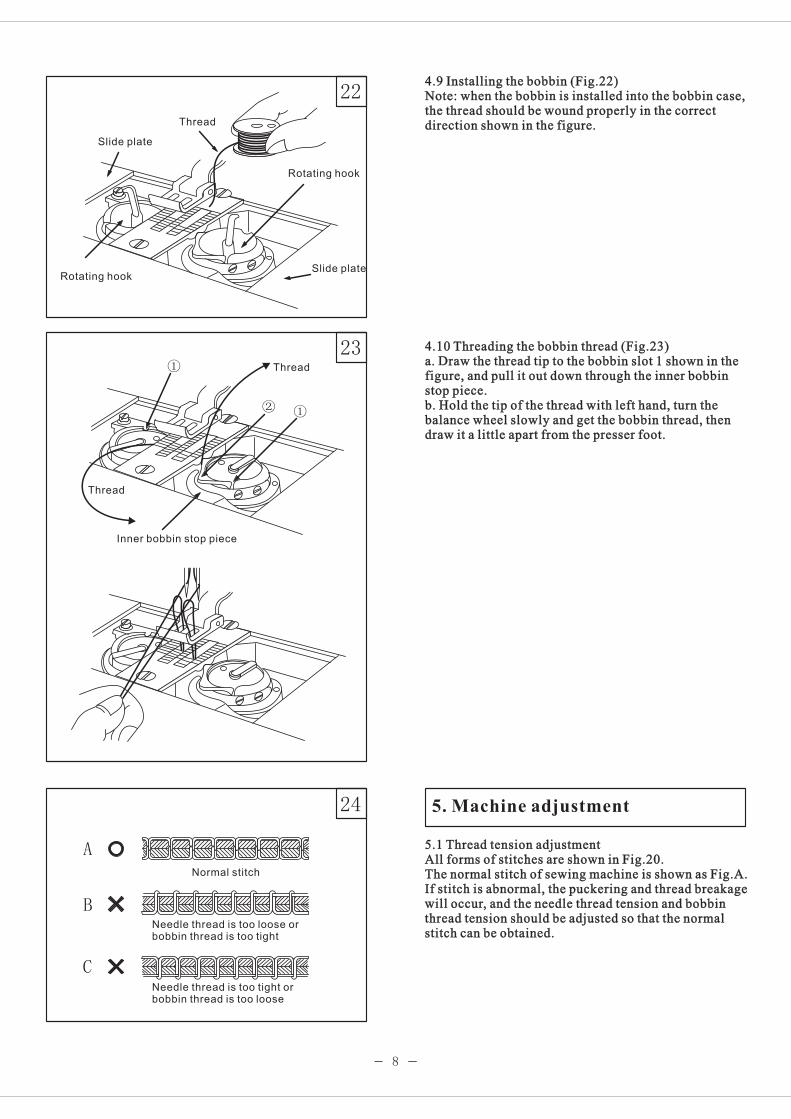
4.9 Installing the bobbin (Fig.22)Note: when the bobbin is installed into the bobbin case,the thread should be wound properly in the correctdirection shown in the figure.
4.10 Threading the bobbin thread (Fig.23)a. Draw the thread tip to the bobbin slot 1 shown in thefigure, and pull it out down through the inner bobbinstop piece.b. Hold the tip of the thread with left hand, turn thebalance wheel slowly and get the bobbin thread, thendraw it a little apart from the presser foot.
5.1 Thread tension adjustmentAll forms of stitches are shown in Fig.20.The normal stitch of sewing machine is shown as Fig.A.If stitch is abnormal, the puckering and thread breakagewill occur, and the needle thread tension and bobbinthread tension should be adjusted so that the normalstitch can be obtained.
5.1 Thread tension adjustmentAll forms of stitches are shown in Fig.20.The normal stitch of sewing machine is shown as Fig.A.If stitch is abnormal, the puckering and thread breakagewill occur, and the needle thread tension and bobbinthread tension should be adjusted so that the normalstitch can be obtained.
5. Machine adjustment
Thread
Rotating hook
Slide plate
Inner bobbin stop piece
Normal stitch
Needle thread is too loose orbobbin thread is too tight
Thread
Thread
Rotating hook
Slide plate
Needle thread is too orbobbin thread is too
tightloose

9
25
28
26
27
a.If the stiich form is the same as shown in Fig.24b, itindicates that the needle thread is too tight or the bobbinthread is too loose. Turn the thread tension screw counterclockwise to release the needle thread tension, or turn theadjusting screw with a screwdriver to increase the bobbinthread tension (Fig.25.26).b.If the needle thread is too loose and the bobbin threadis too tight as shown in Fig,24c, turn the thread tensionscrew clockwise to increase the needle thread tension,or loosen the bobbin lace screw to reduce the bobbinthread tension.(Fig.25,26).For special sewing with special thread, the requiredtension can be obtained by adjusting the strength andstroke of the thread take-up spring.
5.2 Adjusting the pressure of the presser foot (Fig.27)The pressure of the presser foot should be adjustedaccording to the thickness of the sewing materials. Ifstitch on heavy duty materials, the pressure should beincreased by turning the pressure adjusting screw onthe back of the arm clockwise. To reduce the pressure,turn it counter-clockwise.
5.3 Safety clutch deviceThe safety clutch device is to prevent the hook andteeth-belt from destroy when the needle thread is drawninto the hook for abnormal load during the operation.
5.3.1 Function of the safety clutch device (Fig.28)a. When the safety clutch device is working, theteeth-belt will remove the load. The rock shaft stopsrotating., only the upper shaft rotates, then the machinestops work.b. Clean off the needle thread which is drawn in the hook.c. Turn the shaft of the teeth-belt with hand to check ifthe rock shaft can turn smoothly, then reset the safetyclutch device.
Needle thread tension adjusting screw
Loosen
Tighten
Strengthen
Weaken
Pressure adjusting screw
Safety clutch
Pulley
Belt shaft
Stop plate
Strengthen
Weaken
Needle thread tension

10
31
29
30
5.3.2 Resetting the safety clutch devicea. While pressing down the button in the bed surfacewith left hand, turn the balance wheel slowly with righthand in the direction shown in Fig.29.b. When the stop plate stops the balance wheel, morestrength is required to turn the balance wheel to resetthe safety clutch device.c. Release the button. Then the resetting is OK.
5.3.3 Adjusting the strength on the safety clutch device(Fig.30)
a. When the white mark of the eccentric pin aims at thecenter of the rock shaft, it indicates that the strength onthe safety clutch device is at the minimum. When thewhite mark points the outside, the strength is properlyincreased.b. To regulate the strength of it, move the teeth-beltand loosen the set screw of the eccentric pin, then turnthe eccentric pin.c. After adjustment, please tighten the set screw.
5.3.4 Upper feed adjustment (Fig.31)If the upper and lower feed are not in timing duringsewing, the long hole of the horizontal feed crankshould be adjusted to get the length of the upper feed.Adjust as follows:Loosen the special bolt;Move the special bolt upward to reduce upper feedamount;Move the special bolt downward to increase the feedamount. Theoretically, when it is on the reference lineof the horizontal feed crank, the upper feed amountequals to the lower feed amount;After adjustment, tighten the special bolt.
Balance wheel
Button
White mark
Tighten
Loosen
Eccentric
Belt
Lower shaft
Set screw
Link Crank(right)
Reference line
Special boltDecrease the upper feed amountDecrease the upper feed amountDecrease the upper feed amount
Increase the upper feed amountIncrease the upper feed amountIncrease the upper feed amount

32
33
34
9
0~0.5mm
11
5.3.5 Presser foot lift volume adjustment (Fig.32)When stitch on the very elastic material or the thicknessof the sewing material is changed. The adjustmentshould be done in the following order:Loosen the special bolt;When the centerline distance between the special boltand the presser foot lift rear crank is decreased, thepresser foot lift volume will be increased. On thecontrary, the distance is increased, the lift volume willbe decreased.After adjustment, tighten the special bolt. The commonpresser foot lift volume can be adjusted in the range of2-6mm.
5.3.6 Hook oil amount adjustment (Fig.33)It adopts plunger full auto-lubrication system. Evenwhen run at a low speed, it can supply and suck oil verywell. Generally, only the hook oil amount can beadjusted. It can be obtained by the oil amount adjustingscrew. Loosen the nut of the adjusting screw, turn thescrew clockwise to increase the oil amount. On thecontrary, to reduce the oil amount. After adjustment,tighten the nut.
5.4 The movable knife5.4.1 Set the movable knife's original position (Fig.34)a. Turn the balance wheel to lower the needle bar to itslowest position.b. Move the trimming driven crank to make the trimmingroller get into the trimming cam groove.c. Turn the balance wheel until the white mark on thebalance wheel is aligned with the mark line. Thenprimarily set it as the position of the trimming drivencrank. Tighten the concerning screws temporarily toprevent the trimming roller sliding out from thetrimming cam groove.d. Loosen the screw A, B.e. Adjust the movable knife to obtain the clearance of0-0.5mm between the terminal line of the movable lifeand the front end of the fixed knife. Then tighten thescrew A, B.
Crank
IncreaseIncrease
Decrease
Crank link
Special bolt
Adjusting screwAdjusting screwAdjusting screw
Movable knife
Fixed knife
Screw A
Screw B
Crank
DecreaseDecrease
Increase
Crank

12
37
35
36
5.4.2 Adjusting the clearance between the movable knifeand the rotating hook position block. (Fig.35)a. Turn the balance wheel to lower the needle bar to itslowest position.b. Press down the trimming driven crank and turn thebalance wheel, so that the movable knife can go forwardas far as it can go.c. Turn the inner rotating hook by hand to adjust theclearance between the movable knife and bobbin caseposition block to 0.2mm.(Loosen the screw A, B before adjusting.)
5.5 Adjusting the trimming cam (Fig.36)a. Turn the balance wheel to lower the needle bar to itslowest position.b. Maintain the position of needle bar, press down thetrimming driven crank, so that the trimming roller canget into the trimming cam groove.c. Turn the balance wheel, adjust the trimming cam tomake the white mark on the balance wheel align with theposition mark line on the arm, then the movable knifestarts working.(Loosen the two set screws A on the trimming cam beforeadjusting.)
5.6 Adjusting the thread releasing assembly (Fig.37)a. Turn the balance wheel to lower the needle bar to itslowest position.b. Maintain the position of needle bar, press down thetrimming driven crank, so that the trimming roller canget into the trimming cam groove.c. Turn the balance wheel, adjust the trimming cam tomake the white mark on the balance wheel align with theposition mark line on the arm, then the Thread tensiondisc is closed.(Loosen the screws A on the threading releasing cambefore adjusting.)Adjusting the open range of the thread tension disc by thethread releasing roller B and thread releasing cam. Whenadjusting, loosen the adjusting screw C, and shrink thedrawing rope.When carrying out the fine adjustment, loosen the screwcap D, move the outside cover of the drawing roperightward to enlarge the open range of the thread tensiondisc.
Screw A
Screw BMovable knife
Bobbin case
About 0.2mm
Trimming driven crank
Trimming roller
Screw A
Trimming cam
Balance wheel
Red mark
Position mark
ArmCam groove
Balance wheel
Red mark
Position mark
Arm
Screw A
Screw C
Thread releasingvibrating lever
Thread releasingroller B
Thread releasingcam
Trimming cam
Trimming driven crank
Trimming roller
Drawing rope
Screw cap D

38
39
40
60
9
13
5.7 Adjusting the trimming pressure of the movableknife and fixed knife (Fig.38)a. Loosen the set screw A.b. Turn the adjusting screw B to adjust the trimmingtension between the movable knife and the fixed knife.After adjustment, tighten the screw A.Note: If there is too much trimming tension between themovable knife and the fixed knife, it will cause strongmovement and trimming failure. Therefore, the minimumtrimming tension is required.Move the movable knife to make sure that if it can cut thethread sharply.When it can not cut the thread sharply, polish the fixedknife as shown in the Fig.39 and replace the movableknife for a new one.
5.8 Adjusting the needle gauge (Fig.40)a. Uninstall the needle plate, feed dog and the needleclamp.b. Tilt back the machine head.c. Loosen the two screws J.d. Take down the spring M.e. Loosen the rotating hook screws A, B. And adjust theclearance between the rotating hook and the needle.f. Install the spring M.g. When the crank C, D is close to position screw E, F,tighten the screw J.h. Turn the balance wheel to lower the needle bar to itslowest position.i. Loosen the screw cap G, H.j. Press down the trimming driven crank K, adjust thetrimming link L, so that the trimming roller is able toget into the trimming cam groove.k. Adjusting the trimming cam and the trimming roller.1) Press down the trimming driven crank K so that thetrimming roller is able to get into the trimming camgroove.2) Turn the trimming link L, adjust the clearancebetween the trimming roller and trimming cam grooveN to its minimum, then tighten the screw G, H.3) Press down the trimming driven crank K again, andcheck that if the trimming roller is able to get into thetrimming cam groove smoothly.
Fixed knife bracket
Screw A Adjusting screw B
Fixed knife
Hone
Lower shaft
N side
Screw A
Position screw E
Link
Rotating hook saddle (right)
Spring M
Trimming roller
Trimming roller
Trimming cam groove
Trimming cam
Screw ACrank C
Crank DScrew B
Screw J
Screw B
Link L
Trimming crank K
Trimming cam
Trimming roller
Screw cap GRotating hooksaddle (left)
Position pin F
Screw cap H

1
2
3
4
5
6
7
8
9 10
111213
14
45
46
47
1516
1718
19
202122
23
37
38
40
41
4243
14
2425
26
27
28
29
30
31
32
33
34
35
36
39
44
45
48
49 50
51
5253
5455 56
57
58
59 60
61
62
63 64
65 66
6768
69
70 71 72 73
74
7576
77
78798081
8283
84
85868788
899091
9293
94
9596
97
9899
80
14
1.Arm parts

1
23456
7
891011121314151617181920212223242526272829303132333435
36373839
404142434445
1/121311//11//412115152//11////121111121111/1/11/1111111
84WF1-00383WF1-004
84WF1-001A84WF1-001B83WF1-001A83WF1-001B84WF1-002A84WF1-002B83WF1-002A84WF1-002B
1WF1-0151WF1-0161WF1-0171WF1-01122T1-0071WF1-0321WF1-0381WF1-0391WF1-0191WF1-0301WF1-0271WF1-0281WF1-0031WF1-0041WF1-0051WF1-0341WF1-0361WF1-0071WF1-0061WF1-0181WF1-0131WF1-0091WF1-0081WF1-0121WF1-0211WF1-02083WF1-01684WF1-0171WF1-03784WF1-02684WF1-02483WF1-0191WF1-0401WF1-0291WF1-0221WF1-0311WF1-0149WF1-0019WF1-002
84WF1-004A6 3 0 GB117-86M10 35 GB70-85M10 35 GB5781-85
φ2.5 5 GB827-86
SM11/64" 40/8
SM11/64" 40/9
SM11/64" 32/5.4
SM9/64" 40/6.5
SM11/64" 40SM9/64" 40
SM3/16" 28
15
/11213//11//11412115152111111111111121211111/1111/111111
No. Part Number NameQt.
RemarkGC20606-D2 GC20606-1-D2
Bed
ArmPinScrewScrewTrade mark (in Chinese)Trade mark (in English)
Model plate (in Chinese)Model plate (in English)
NailUpper thread guideScrewRear coverScrewWasherCoverFront slide plateScrewThread take-up lever guardBack front coverScrewSpringThread retainerLower thread fingerScrewScrewScrewScrewMiddle thread fingerRubber plugFace plateScrewUpper thread fingerGuide set plateSet plateOil retainerNeedle plateNeedle platePin shaftThread releasing shaftRight sliding plateLeft sliding plateLeft sliding plateRubber plugRubber plugCoverRubber plugLower thread fingerOil felt
1.Arm parts

1
2
3
4
5
6
7
8
9 10
111213
14
45
46
47
1516
1718
19
202122
23
37
38
40
41
4243
14
2425
26
27
28
29
30
31
32
33
34
35
36
39
44
45
48
49 50
51
5253
5455 56
57
58
59 60
61
62
63 64
65 66
6768
69
70 71 72 73
74
7576
77
78798081
8283
84
85868788
899091
9293
94
9596
97
9899
80
16
1.Arm parts

464748
495051525354555657585960616263646566676869707172737475767778798081828384858687888990
919293949596
979899
111/2111111111111/121121111112//11111///1////1/111121//11
1WF1-04322T2-00484WF1-02783WF1-0051WF1-010Q84WF1-01084WF1-010P84WF1-01284WF1-01184WF1-01484WF1-013
84WF1-005A1WF1-01184WF1-01684WF1-01513WF2-05284WF1-00613WF2-05122T1-009E313WF2-00936T2-006D484WF1-005B84WF1-0061WF1-00527WF2-008C27WF2-008B15320927WF2-008A27WF2-008F1WF1-010M83WF1-005A84WF1-005C1WF1-010H83WF1-0111WF1-02621WF4-04683WF1-01283WF1-01384WF1-01484WF1-00183WF1-01083WF1-0079WF1-003B83WF1-00883WF1-00984WF1-0101WF1-0241WF1-010L84WF1-0261WF1-02584WF3-00384WF1-01883WF1-01683WF1-01784WF1-01984WF1-020
GB896-86-5
17
No. Part Number NameQt.
RemarkGC20606-D2 GC20606-1-D2
11/121111111111121142231122224111111111121111/111116/1111
Spring retaining plateScrewThread tension assemblyThread tension assemblyScrewThread releasing erecting plateSpringScrewThread releasing vibrating leverScrewSet plateRetainerSet plateScrewSpringButtonNutBolt (long)BoltThread tension discSpringNutPinThread guideScrewThread releasing plateSpringStop plateThread tension nut assemblyThread tension plateThread releasing stud (short)Thread tension bolt (right)Thread tension bolt (left)NutBushingScrewPosition bracketGuide coverScrewBushingThread control assemblyThread take-up springThread guide plateThread take-up springPosition screwThread take-up spring shaftThread take-up spring shaftScrewThread releasing stud (long)Thread releasing leverPosition plateScrewCoverCoverRound coverBed legScrew
1.Arm parts

12
3 4
5
67
89
10
11
12
13
14
15 16
17
18
19
20
21
22 23
24
25
26
27
28
29
3031
32
33
34
35 37 3839 4041 42 43
4445
46
4748
49
5051
52
53
54
55 56
36
148
13
18
2. Upper shaft and presser foot parts

1234567891011121314151617181920212223242526272829303132333435363738394041424344454647484950515253545556
11111113111133111212111111111111111111131221111112211121
1WF2-0251WF2-0221WF2-0231WF2-0241WF2-0211WF2-0201WF2-0071WF2-0101WF2-0091WF5-026
1WF5-0411WF2-0261WF2-0301WF2-029
1WF2-0311WF2-01984WF2-0011WF2-0441WF2-0281WF2-0391WF2-0371WF2-041
1WF2-0401WF2-0481WF2-0451WF2-0421WF2-0461WF2-0471WF2-0381WF5-0011WF5-0251WF5-044
1WF5-0231WF5-0241WF5-0451WF4-0181WF5-0381WF5-0281WF5-0371WF5-0301WF5-0291WF5-0321WF5-0331WF5-0341WF5-035
1WF5-0421WF2-0271WF2-03743WF3-004JO.0.4043WF2-003
SM1/4" 24/13Felt
SM9/32"/28GB7-1SM1/4" 40/7SM1/4" 40/4
25 GB894.1-86
SM15/64" 28/8.5SM15/64" 28/15
SM15/64" 28/12
SM15/64" 28/4.5
3 GB896-86
SM15/64" 28/10.5SM15/64" 28/10
Washer 6 GB95-85
SM1/4" 24/16
SM1/4" 24/8
SM11/64" 40/6
Washer 4 GB848-85SM11/64" 40/10
φ
φ
19
2. Upper shaft and presser foot parts
No. Part Number NameQt.
RemarkGC20606-D2 GC20606-1-D2
Upper shaftFront bushingScrewOil feltNeedle bar crankSet screwPosition screwPosition screwScrewEccentric wheelElastic retainerSlide grooveRetainerScrewPosition screwBall bearingRear bushingScrewBalance wheelScrewSynchronic beltSpring platePinSpringSplit retainerStop plateStudRetaining plateConnecting pieceBushingPosition screwSet screwNutEccentric linkConnecting boltWasherOil tube assemblySpringRear crankScrewFront crankScrewBushingPresser foot lifter linkScrewScrewPresser foot lifter swing plateBall shaftBallWasherScrewTiming wheelTiming wheelRotating shaftScrewMiddle bushing
11111113111133111212111111111111111111131221111112211121

1 2 3 4 5 6 7 8 9 10
11
12 13
14
15
16
17
18
19
20
21
22
232425
26
27
28
29
30
31
32 33
34
35
36 37
38
39
40
41
4243 44 46 47 48 49
53
5455565758
5960
4243 45 1
50
51
52
45
59 61
62
63
64 656667
6869
70
71
72737475 76
77
78
79
80
45565754
33
3435
GC20606-D2
GC20606-1-D2
20
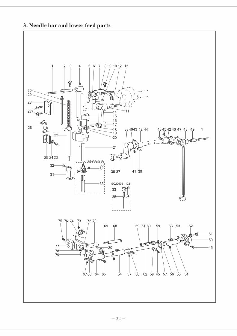
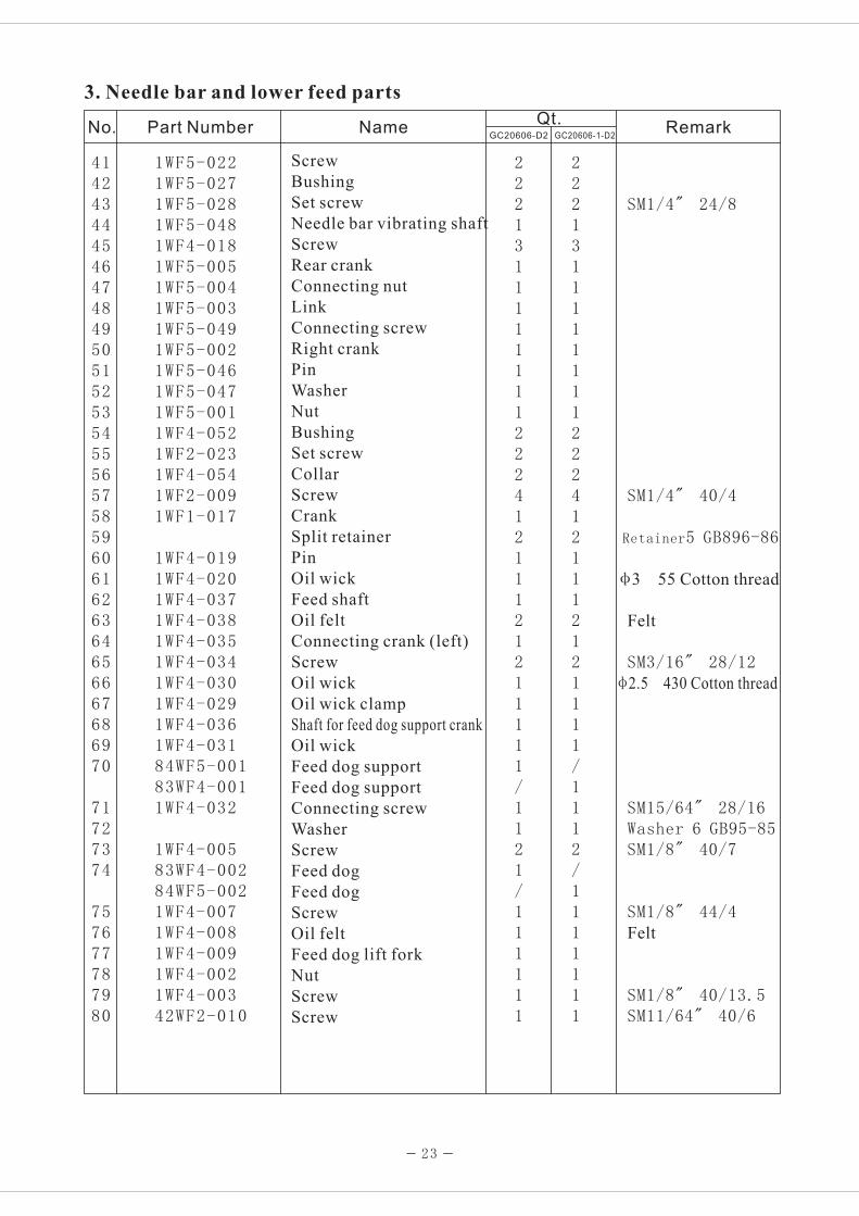
3. Needle bar and lower feed parts

No. Part Number NameQt.
RemarkGC20606-D2 GC20606-1-D2
123456789101112131415161718192021
22232425262728293031
3233
34
353637383940
21111111111111162111/1111112111/11/1/1211111
1WF5-0171WF5-0181WF5-0311WF5-0191WF2-0181WF2-0171WF2-0161WF2-0111WF2-0191WF2-0121WF2-0131WF2-0141WF2-0151WF2-0081WF5-0111WF5-0131WF5-0121WF2-0071WF2-0051WF2-0061WF2-0049WF2-0011WF2-0061WF5-010
1WF5-0091WF5-0361WF3-0091WF5-0141WF5-0161WF5-0151WF5-04335T5-50222T2-0041WF2-00335T1-1031WF2-00222T2-017
1WF5-0071WF5-0081WF5-020
1WF5-021
φ2.5 80 Cotton thread
SM5/16" 28/10SM15/64" 28/8φ Cotton thread2.5 240
SM15/64" 28/12φ3 25
φ Cotton thread3 80
SM3/32" 56/4.6
SM9/64" 40/8.5
SM11/64" 40/12Washer GB848-85
SM11/64" 40/15
SM9/64" 40/4.3
DP 17 23#
A4 24 GB117-86
21
3. Needle bar and lower feed parts
Oil wick
Shaft
Screw
Screw
Oil wick
Bushing
Thread take-up lever
Slide block
Screw
Oil wick
Choke plug
Pin
Oil wick
Needle bar link
Needle bar vibrating bracket
Screw
Gasket
Oil felt
Needle bar adaptor
Screw
Needle bar
Needle bar
Presser bar
Screw
Washer
Needle bar holder guide plate
Presser bar link
Screw
Needle bar vibrating bracket guide plate
Spring
Spring reel
Walking presser foot
Walking presser foot
Screw
Needle clamp
Needle bar thread guide
Screw
Screw
Needle
Slide block
Slide block groove
Left crank
Pin
Washer
211111111111111621111/1111121111/11/2/211111
1 2 3 4 5 6 7 8 9 10
11
12 13
14
15
16
17
18
19
20
21
22
232425
26
27
28
29
30
31
32 33
34
35
36 37
38
39
40
41
4243 44 46 47 48 49
53
5455565758
5960
4243 45 1
50
51
52
45
59 61
62
63
64 656667
6869
70
71
72737475 76
77
78
79
80
45565754
33
3435
GC20606-D2
GC20606-1-D2
22
3. Needle bar and lower feed parts
414243444546474849505152535455565758596061626364656667686970
71727374
757677787980
22213111111112224121112121111/1112/1111111
1WF5-0221WF5-0271WF5-0281WF5-0481WF4-0181WF5-0051WF5-0041WF5-0031WF5-0491WF5-0021WF5-0461WF5-0471WF5-0011WF4-0521WF2-0231WF4-0541WF2-0091WF1-017
1WF4-0191WF4-0201WF4-0371WF4-0381WF4-0351WF4-0341WF4-0301WF4-0291WF4-0361WF4-03184WF5-00183WF4-0011WF4-032
1WF4-00583WF4-00284WF5-0021WF4-0071WF4-0081WF4-0091WF4-0021WF4-00342WF2-010
SM1/4" 24/8
SM1/4" 40/4
Retainer5 GB896-86
φ3 55 Cotton thread
Felt
SM3/16" 28/12φ Cotton thread2.5 430
SM15/64" 28/16Washer 6 GB95-85SM1/8" 40/7
SM1/8" 44/4Felt
SM1/8" 40/13.5SM11/64" 40/6
23
3. Needle bar and lower feed parts
No. Part Number NameQt.
RemarkGC20606-D2 GC20606-1-D2
222131111111122241211121211111/1121/111111
Screw
Bushing
Set screw
Needle bar vibrating shaft
Screw
Rear crank
Connecting nut
Link
Connecting screw
Right crank
Pin
Washer
Nut
Bushing
Set screw
Collar
Screw
Crank
Split retainer
Pin
Oil wick
Feed shaft
Oil felt
Connecting crank (left)
Screw
Oil wick
Oil wick clamp
Shaft for feed dog support crank
Oil wick
Feed dog support
Feed dog support
Connecting screw
Washer
Screw
Feed dog
Feed dog
Screw
Oil felt
Feed dog lift fork
Nut
Screw
Screw

1
2
3
4
5
6
7
8
9
10
11
12
13
14
1516
17
18
19
20 21
222324
25
27
28
29
30
31 32 33 34 35 36 37
38
39
40
41
42 43 44 45 46 47 48
49
50 51 52
53 54
28
24
26
4. Lower shaft and thread looping parts

123456789101112131415161718192021222324252627282930313233343536373839404142434445464748495051525354
111111111111111111111111111421111111111121111111111311
84WF2-0031WF2-0601WF2-0591WF2-06184WF2-0041WF2-0651WF2-0701WF2-0691WF2-07284WF2-0051WF2-0751WF2-026
1WF2-076
1WF2-0741WF2-0621WF2-034
1WF2-0331WF2-0771WF2-0671WF2-0661WF2-04483WF2-0011WF2-0521WF2-0781WF2-0091WF2-0791WF2-0551WF2-03584WF2-0021WF2-05684WF5-0031WF2-0191WF2-0571WF2-058
1WF4-0411WF4-0421WF4-0101WF4-0111WF4-012
1WF2-0551WF2-0511WF2-0091WF2-052
1WF2-0501WF2-0491WF4-0441WF4-043
SM14/64" 28
φ2.5 14 Cotton thread
SM3/16" 32
SM9/64" 40/4.5Washer 4 GB848-85
Washer 4 GB848-85SM3/16" 32
SM3/16" 28/14.5Washer 6 GB95-85SM1/4" 24/20
SM3/16" 28SM3/16" 28/25.5SM1/4" 40/5
SM1/4" 40/4
φ25 45 Cotton thread
SM15/64" 28/12
φ2.5 85 Cotton threadWasher 5 GB896-86
SM15/64" 28/13.5
Washer 26 GB894.1-86
SM1/4" 40/4SM1/4" 40/5
SM9/64" 40/7
25
4. Lower shaft and thread looping parts
No. Part Number NameQt.
RemarkGC20606-D2 GC20606-1-D2
Right hook saddleScrewUpper bushingLower bushingRotating hook assemblyBobbinOil wickHinge shaftScrewConnecting leverThread finger bracketScrewWasherThread fingerWasherNutBushingScrewWasherScrewBushingNutScrewScrewLeft hook saddleScrewSpiral gearScrewSpiral gearFeed linkLeft bushing for lower shaftOil wickLower shaftFeed dog lift camScrewRight bushing for lower shaftOil wickRetainerSpringButtonSet screwFeed camFeed linkNeedle bearingRetainerMiddle bushing assemblyRear bushing for lower shaftScrewScrewBall bearingBearing pressure ringSet screwOil wickPin
122222222222222222222222122821111111111121111111111311

1
2
3
4
5
6
789
10
11
12
13
1617 18
14 15
19 20
21
22
23
24
25
19
26
2728 29
30 31
32
33
34
35
36 37
38 39
404142
434445
46 47
4849
50
6465
51
52
53 54
555657
585960
616263
26
5. Automatic reverse feed and testing parts

123456789101112131415161718192021222324252627282930313233343536373839404142434445
121111133111111111211112111111221112111121111
121111133111111111211112111111221112111121111
62WF5-03221WF1-0622KT6-0152KT6-0142KT6-013
78WF2-00584WF1-02121WF3-0262KT8-0022KT8-00384WF1-02284WF1-023
84WF4-023A84WF4-023B84WF4-023C84WF4-023D84WF4-023E84WF4-023F84WF4-023G84WF4-00984WF4-0111WF2-03084WF4-01384WF4-01284WF4-01484WF1-0101WF4-0271WF4-0216K2-04084WF4-00884WF4-01684WF4-01584WF4-0221WF4-0301WF4-02621WF4-0556K3-01784WF4-00484WF4-00384WF4-00284WF4-00784WF4-00684WF4-005
060300606
8003-HGB894.1-86-30
27
5. Automatic reverse feed and testing parts
Position bracket
Screw
Switch
Connecting part
Switch bracket
Screw
Switch assembly
Clamp
Screw
Plug adapter
Cover
Clamp
Sensor assembly
C-type retainer
Retainer
Washer
Spacer B
Reflecting plate (upper)
Spacer A
Reflecting plate (lower)
Probe unit assembly
Reverse feed lever
Crank
Screw
Position screw
Rubber band
Spring
Reverse feed lever shaft
Screw
Position screw
Nut
Connecting screw
Spring
Crank
Stitch length adjusting bar
Screw
Position screw
Position screw
Nut
Electromagnet
Screw
Electromagnet holder
Draw bar
Screw
Crank
No. Part Number NameQt.
RemarkGC20606-D2 GC20606-1-D2

1
2
3
4
5
6
789
10
11
12
13
1617 18
14 15
19 20
21
22
23
24
25
19
26
2728 29
30 31
32
33
34
35
36 37
38 39
404142
434445
46 47
4849
50
6465
51
52
53 54
555657
585960
616263
28
5. Automatic reverse feed and testing parts
4647484950515253545556575859606162636465
11111112111211122411
11111112111211122411
01784WF4-0201WF4-0241WF5-006C31WF4-023
84WF4-0186K2-04384WF4-02184WF4-0191WF4-0531WF4-0161WF4-0451WF4-0571WF4-0391WF4-0401WF4-0561WF1-0111WF4-0221WF5-009
84WF4-
14 2 .4 GB1235-86
29
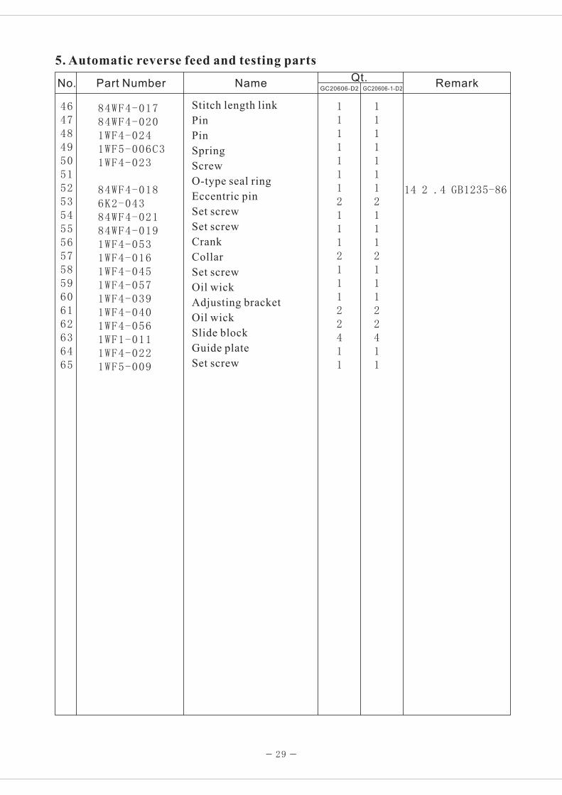
5. Automatic reverse feed and testing parts
No. Part Number NameQt.
RemarkGC20606-D2 GC20606-1-D2
Stitch length link
Pin
Pin
Spring
Screw
O-type seal ring
Eccentric pin
Set screw
Set screw
Crank
Collar
Set screw
Oil wick
Adjusting bracket
Oil wick
Slide block
Guide plate
Set screw

30
2122
23
2425
1
2
3
4 5
6
7
8 9 10 11 12
13
14
15
161718
19
20
4
11
26
27
28
29 3031
32
33
34
35
36 37
38
39
40
41
42
43
44
4546
4748
4950
51
5253
54
55
56 57
58
59
60
61 62 6364 65
66
67
68
69 70
71 72
7374
75
7677
78
79
80
8182
8384
8539
86
87
88
48
76
55
89
6. Thread releasing and auto-trimming parts

123456789101112131415161718192021222324252627282930313233343536373839404142434445
111312131121/11111//31111111111211122141////2
222624262242122///113111111111121112214111122
84WF3-01484WF3-01584WF3-01384WF3-00384WF3-00784WF3-00284WF3-00984WF3-00284WF3-00484WF3-01084WF3-01284WF3-01183WF3-00384WF3-01784WF3-01684WF3-00684WF3-00584WF3-00883WF3-00183WF3-0021WF1-01184WF3-01884WF3-01984WF3-02284WF3-02184WF3-02084WF3-02384WF3-02484WF3-05884WF3-05984WF3-04184WF3-03084WF3-02984WF3-03284WF3-03184WF1-0211WF1-01184WF3-025
1WF1-00583WF3-00483WF3-00583WF3-00683WF3-00922T7-008
GB41-86-M5
31
6. Thread releasing and auto-trimming parts
No. Part Number NameQt.
RemarkGC20606-D2 GC20606-1-D2
Adjusting screw
Set screw
Set table
Screw
Fixed knife
Screw
Movable knife
Screw
Position screw
Spring
Screw
Spring
Guide bracket (left)
Roller
Trimming vibrating lever assembly
Pressure plate (right)
Set table (right)
Guide bracket (right)
Set table (left)
Pressure plate (left)
Screw
Connecting bracket
Pin
Spring
Pin
Crank
Screw
Thread releasing steel cable assembly
Crank (right)
Screw
Spring
Set screw
Slide block
Connecting screw
Connecting plate
Clamp
Screw
Set plate
Nut
Screw
Crank (left)
Screw
Draw bar (long)
Set screw
Pin

32
2122
23
2425
1
2
3
4 5
6
7
8 9 10 11 12
13
14
15
161718
19
20
4
11
26
27
28
29 3031
32
33
34
35
36 37
38
39
40
41
42
43
44
4546
4748
4950
51
5253
54
55
56 57
58
59
60
61 62 6364 65
66
67
68
69 70
71 72
7374
75
7677
78
79
80
8182
8384
8539
86
87
88
48
76
55
89
6. Thread releasing and auto-trimming parts

4647484950515253545556575859606162636465666768697071727374757677787980818283848586878889
112121111321///22121111212112231112111111222
11212111132112222121111212112231113111111222
84WF3-02684WF3-0446K3-01784WF3-03384WF3-03584WF3-03484WF3-042A84WF3-042B84WF3-042C84WF3-0431WF2-03884WF3-06183WF3-007
83WF3-00884WF3-05584WF3-05484WF3-056
84WF3-05784WF3-03684WF3-04084WF3-02784WF3-03884WF3-03721WF1-02284WF3-06084WF3-02859WF2-003I21WF2-04321WF4-04784WF3-04884WF3-05084WF3-03984WF3-04784WF3-04584WF3-04684WF3-05384WF3-05221WF4-05584WF3-0491WF6-0361WF1-02621WF1-051
GB97.1-85-5
33
6. Thread releasing and auto-trimming parts
No. Part Number NameQt.
RemarkGC20606-D2 GC20606-1-D2
Thread releasing vibrating lever assembly
Spring
Nut
Connecting nut
Screw
Pressure plate
Crank
Slide block
Set screw
Screw
Screw
Position bushing
Draw bar (short)
Washer
Connecting screw
Connecting screw
Adapter assembly
Adapter bracket
Nut
Connecting screw
Guide shaft
Crank shaft
Pin
Position screw
Thread realeasing cam
Screw
Trimming cam
Spring
Screw
Set screw
Screw
Position plate
Set plate
Set plate
Screw
Electromagnet vibrating lever
Screw
Trimming electromagnet vibrating lever
Crank
Screw
Electromagnet
Clamp
Screw
Nut

12
3 4 5 6
78
9
10
11 12
13
14
151617
18
19
20
21
22
23
24
25
26
27
28
29
30
31
32
33
34
3536
37
38
39 40 41
42
43
44
4546
4748
49
34
19
7. Knee control presser foot lift parts
1234567891011121314151617
1819202122232425262728293031323334353637383940414243444546474849
1211111111111111/112111111112111111112211121111111
12111111111111111/12111111112111111112211121111111
1WF5-0401WF5-0391WF3-0111WF3-0101WF3-013
3 141WF3-0121WF3-0151WF3-016
79
1 21 201WF3-0241WF3-0251WF3-0019WF3-0011WF3-0021WF3-0041WF3-0051WF2-0061WF3-0231WF3-0221WF3-0071WF3-0081WF3-0091WF3-0031WF3-0231WF3-00622F9-01258F0-001A158F0-00122T9-001A222T9-001A3
1WF3-02822T9-001A922T9-001A1022T9-007C222T9-001A71WF3-02722T9-003B422T9-003B322T9-003B222T9-003B722T9-003B622T9-003B522T9-003B81WF3-026
1WF -0
1WF3-0181WF3-011WF3-01WF3-0 1WF3-0
SM1/64" 40/12SM1/4" 24/16.5
SM9/64" 40/8.5
SM11/64" 40/15
SM1/4" 24 23
SM5/16" 25/10
φ9 GB896-86
SM15/64" 28/28
SM15/64 28/15
SM5/16 18/13
SM15/64"28/18
35
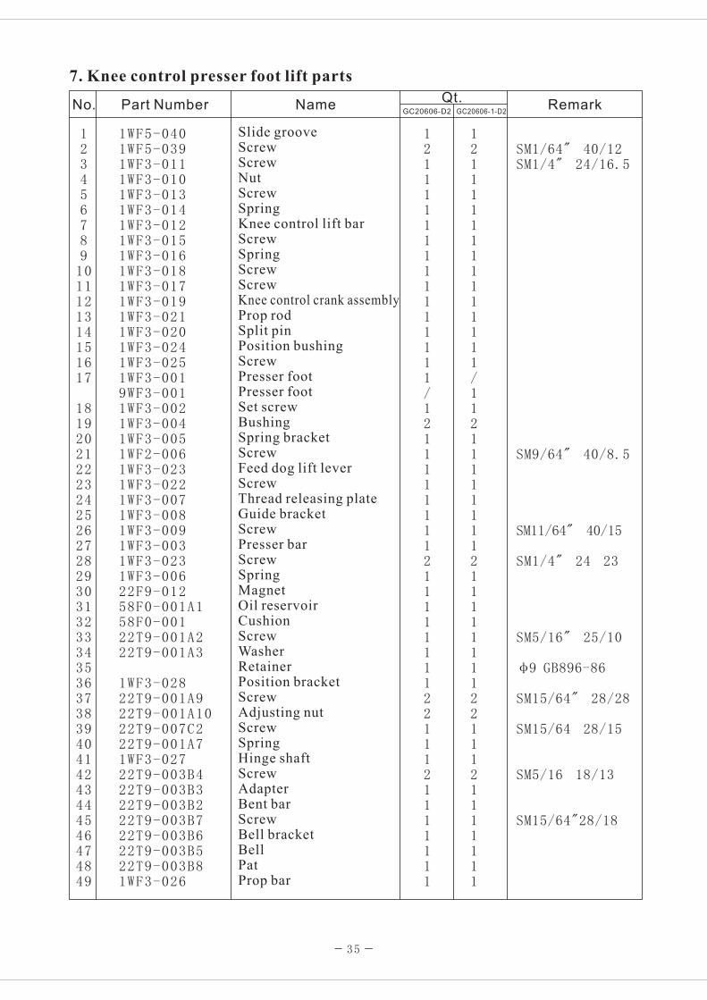
7. Knee control presser foot lift parts
Slide grooveScrewScrewNutScrewSpringKnee control lift barScrewSpringScrewScrewKnee control crank assemblyProp rodSplit pinPosition bushingScrewPresser footPresser footSet screwBushingSpring bracketScrewFeed dog lift leverScrewThread releasing plateGuide bracketScrewPresser barScrewSpringMagnetOil reservoirCushionScrewWasherRetainerPosition bracketScrewAdjusting nutScrewSpringHinge shaftScrewAdapterBent barScrewBell bracketBellPatProp bar
No. Part Number NameQt.
RemarkGC20606-D2 GC20606-1-D2

1
2
3 4
5
6 7 8
9
10 11 12 13 14
15
16
17
18
19
20 21
22232425
26
27
28
293031
32
33
3435363738
39
40 41 42
43
44
45
4647 48
49
1616 2323
23
16 20
21
26 20
21
36
8. Lubrication parts

12345678910111213141516171819202122232425262728293031323334353637383940414243444546474849
11111112111111110111441821211111111113111/3211/1/1
1WF6-0011WF6-0341WF6-0031WF6-005A1WF6-0041WF6-0071WF6-008
1WF6-0091WF6-0061WF6-0101WF6-0111WF6-0021WF6-0131WF6-0121WF1-024
1WF6-0421WF6-0141WF1-01122T1-0071WF6-0211WF1-0261WF2-0531WF2-0541WF6-0271WF6-0251WF6-0241WF6-0231WF6-0261WF6-0181WF6-0191WF6-0201WF6-0171WF6-0281WF6-035
6 361WF6-0381WF6-0411WF6-0401WF6-0391WF6-0341WF6-0321WF6-0371WF6-0331WF6-0301WF6-0311WF6-0291WF6-015
1WF -0
SM3/16" 28/12Felt3D 0.5 60Cotton threadDrganic glassOil resistant rubberM4 16 GB69-85
3D 1 4005D 1 400φ2.5 550 Cotton thread
3D 0.5 150SM9/64" 40/9Washer 4 GB7246-87
SM /64" 4 0/11 9
SM /64" 4 0/9 4.5SM 1/ 4"1 6 40/10
3D 1 90
SM1/8" 44/4.5
H62 Bronze
3D 0.5 4103D 1 445
3D 0.5 220φ2.5 300φ2.5 240
37
8. Lubrication parts
SpringScrewOil feltOil pipeOil wickOil potOil top coverScrewPinSpringOil pipeOil pipeOil wickPosition clampOil pipeScrewWasherOil pipe clampSpringScrewWasherClampScrewScrewBushingOil pipePlungerSpringRetaining plateScrewOil filterWasherFilter screenSet plateOil pipe clampOil pipeClampOil tray assemblyOil wickOil pipeOil pipeClampOil pipeOil wickOil wickSet clampOil pipe clamp3-nozzle oil mouth assemlySet clamp
No. Part Number NameQt.
RemarkGC20606-D2 GC20606-1-D2
11111112111111110111441821211111111113211132111111
φ2.5 430 Cotton thread

1
2
3
4
5
6
7
8
9
10
11
12
13
14
15
16
17
18
19
20
21
22
38
9. Accessory

1
2
3
4
5
6
7
8
9
10
11
12
13
14
15
16
17
18
19
20
21
22
1
2
2
2
2
4
1
1
1
1
1
1
1
1
1
1
1
1
/
1
1
1
1
1
2
2
2
2
4
1
1
1
1
1
1
1
1
1
1
1
1
1
/
1
1
1
33TF-010
22T9-007F1
22T9-007F2
22T9-009
22T9-010
1WF2-065
33TF-011
33TF-016
13F-009
1F-010
1F-011
33TF-012
33TF-013
33TF-014
58T0-007C
22T9-018
1F-012
S14420020
1F-014
33TF-019
78WF7-001
1WF7-012
V-type 1050
S=2mm
S=2.5MM
S=3MM
DP 1 7 23#
39
9. Accessory
No. Part Number NameQt.
RemarkGC20606-D2 GC20606-1-D2
Accessory bag
Hinge pin
Hinge pin socket
Cushion
Cushion
Bobbin
Oil pot
V-belt
Spanner
Spanner
Spanner
Screwdriver
Screwdriver
Screwdriver
Thread tweezer assembly
Arm cover
Oil tank
Bobbin winder
Thread spool stand
Thread spool stand
Probe unit adusting plate
Needle
Safety guard assembly

1. Brief introduction..........................................................................................1
2. Main specifications........................................................................................1
3. Installation and preparation.........................................................................1-4
4. Operation...................................................................................................4-8
5.Machine adsjustment..................................................................................5-13
1. Arm parts...............................................................................................14-17
2. Upper shaft and presser foot parts............................................................18-19
3. Needle bar and lower feed parts................................................................20-23
4. Lower shaft and thread looping parts.........................................................24-25
5. Automatic reverse feed and testing parts....................................................26-29
6. Thread releasing and auto-trimming parts..................................................30-33
7. Knee control presser foot lift parts............................................................34-35
8. Lubrication parts.....................................................................................36-37
9. Accessory...............................................................................................38-39
Content
Operation Instruction
Parts Manual

XI´AN TYPICAL EUROPE GmbHHertelsbrunnenring 9 D-67657 KaiserslauternTel.: +49 (0)631 316019-0Fax: +49 (0)631 316019-11
E-mail: [email protected]
Certifi cate of theinternational ISO9001
Certifi cate of theISO14001
Certifi cate of theinternational CE
Certifi cate forEcolabelling Product
Certifi cate for EnergyConservation Product
SIN
GLE
/ D
OU
BLE
NEE
DLE
MED
IUM
&
HEA
VY-D
UTY
WIT
H T
HRE
AD
CU
TTER
& B
ACK
TA
CK
GC20606-D2
GC20
606-
1D2/
/206
06-D
2 –
Man
ual –
EN
– 0
8-20
10
This machine may only be operated by adequately trained operators only after having completely read and understood the instruction manual.
Parts are subject to changes in design without prior notice.