Embed Size (px)
Citation preview

Operator’s ManualMODELS 2165 / 2175 / 2185 / 2195
ASSEMBLY • OPERATION • MAINTENANCE
BACKHOES
703 $4.00 50033329
BUSH HOG,L.L.C.®
CONGRATULATIONS!You have invested in the best implement of its type on the market today.
The care you give your Great Bend implement will greatly determine your satisfactionwith its performance and its service life. We urge a careful study of this manual to provideyou with a thorough understanding of your new implement before operating, as well assuggestions for operation and maintenance.
If your manual should become lost or destroyed, Great Bend will be glad to provide you witha new copy. Order from Great Bend, P. O. Box 1039, Selma, Alabama 36702-1039.
As an authorized Great Bend dealer, we stock genuine Great Bend parts which aremanufactured with the same precision and skill as our original equipment. Our trainedservice personnel are well informed on methods required to service Great Bend equipment,and are ready and able to help you.
Should you require additional information or assistance, please contact us.
YOUR AUTHORIZEDGREAT BEND DEALER
BECAUSE GREAT BEND MAINTAINS AN ONGOINGPROGRAM OF PRODUCT IMPROVEMENT, WE RESERVE THE RIGHT TO MAKE IMPROVEMENTS IN DESIGN OR CHANGES IN SPECIFICATIONS WITH-OUT INCURRING ANY OBLIGATION TO INSTALL THEM ON UNITS PREVIOUSLY SOLD.
BECAUSE OF THE POSSIBILITY THAT SOMEPHOTOGRAPHS IN THIS MANUAL WERE TAKEN OF PROTOTYPE MODELS, PRODUCTION MODELS MAY VARY IN SOME DETAIL. IN ADDITION, SOMEPHOTOGRAPHS MAY SHOW SHIELDS REMOVED FOR PURPOSES OF CLARITY. NEVER OPERATETHIS IMPLEMENT WITHOUT ALL SHIELDS IN PLACE.
BACKHOESOperator’s Manual
TABLE OF CONTENTS
SECTION/PARA PAGEWarranty . . . . . . . . . . . . . . . . . . . . . . . . . . . . . 2Dealer Preparation Check List . . . . . . . . . . . . . 3 Safety Procedures. . . . . . . . . . . . . . . . . . . . . . 5Federal Laws and Regulations. . . . . . . . . . . . . 7General Operation. . . . . . . . . . . . . . . . . . . . . . 8Controls . . . . . . . . . . . . . . . . . . . . . . . . . . . . . 8Operating The Backhoe. . . . . . . . . . . . . . . . . . 9Transporting The Backhoe. . . . . . . . . . . . . . . 10Placing The Stabilizers . . . . . . . . . . . . . . . . . 11Filling The Bucket . . . . . . . . . . . . . . . . . . . . . 12Dumping The Bucket . . . . . . . . . . . . . . . . . . . 12Trenching . . . . . . . . . . . . . . . . . . . . . . . . . . . 12Back Filling . . . . . . . . . . . . . . . . . . . . . . . . . . 13Service . . . . . . . . . . . . . . . . . . . . . . . . . . . . . 14Beginning Of Season. . . . . . . . . . . . . . . . . . . 14Hydraulic System . . . . . . . . . . . . . . . . . . . . . 14
RETAIL CUSTOMER’S RESPONSIBILITYUNDER THE GREAT BEND WARRANTY
It is the Retail Customer and/or Operator’s responsibility to read the Operator’s Manual, to operate, lubricate,maintain, and store the product in accordance with all instructions and safety procedures. Failure of the opera-tor to read the Operator’s Manual is a misuse of this equipment.
It is the Retail Customer and/or Operator’s responsibility to inspect the product and to have any part(s) repairedor replaced when continued operation would cause damage or excessive wear to other parts or cause a safetyhazard.
It is the Retail Customer’s responsibility to deliver the product to the authorized Great Bend dealer from whomhe purchased it, for service or replacement of defective parts which are covered by warranty. Repairs to be sub-mitted for warranty consideration must be made within forty-five (45) days of failure.
It is the Retail Customer’s responsibility for any cost incurred by the Dealer for traveling to or hauling of theproduct for the purpose of performing a warranty obligation or inspection.
1
SECTION/PARA PAGETooth Replacement 15Lubrication 15Removal / Storage 16Stabilizer Pads 17Hydraulic Trouble Shooting 17Valve Repair 23Assembly 24Mounting Kit Instructions 25PTO Pump Kits 30Hydraulic Hook-Up To Tractor 31Power Beyond Kit 35Flow Divider Kit 38General Specifications 42Removing From Shipping Pallet 43Safety Decals 44Torque Specifications 45

Great BendLIMITED WARRANTY
✯✯✯✯✯✯✯✯✯✯✯✯✯✯✯✯✯✯✯✯✯✯✯✯✯✯✯✯✯✯✯Great Bend / Bush Hog L.L.C., warrants to the original purchaser of any new Great Bend equipment,
purchased from an authorized Great Bend dealer, that the equipment be free from defects in material and work-manship for a period of one (1) year for non-commercial, state, and municipalities’ use and ninety (90) days forcommercial use from date of retail sale. The obligation of Great Bend / Bush Hog L.L.C. to the purchaser underthis warranty is limited to the repair or replacement of defective parts.
Replacement or repair parts installed in the equipment covered by this limited warranty are warrantedfor ninety (90) days from the date of purchase of such part or to the expiration of the applicable new equip-ment warranty period, whichever occurs later. Warranted parts shall be provided at no cost to the user at anauthorized Great Bend dealer during regular working hours. Great Bend reserves the right to inspect any equip-ment or parts which are claimed to have been defective in material or workmanship.
DISCLAIMER OF IMPLIED WARRANTIES & CONSEQUENTIAL DAMAGESGreat Bend’s obligation under this limited warranty, to the extent allowed by law, is in lieu of all war-
ranties, implied or expressed, INCLUDING IMPLIED WARRANTIES OF MERCHANTABILITY AND FITNESSFOR A PARTICULAR PURPOSE and any liability for incidental and consequential damages with respect to thesale or use of the items warranted. Such incidental and consequential damages shall include but not be limitedto: transportation charges other than normal freight charges; cost of installation other than cost approved byGreat Bend; duty; taxes; charges for normal service or adjustment; loss of crops or any other loss of income;rental of substitute equipment, expenses due to loss, damage, detention or delay in the delivery of equipment orparts resulting from acts beyond the control of Great Bend.
THIS LIMITED WARRANTY SHALL NOT APPLY:
1. To transportation to and from dealership or service calls made by dealers, ie, driving time, towing, pickup and delivery.
2. To vendor items which carry their own warranties, such as engines, tires, and tubes.
3. If the unit has been subjected to misapplication, abuse, misuse, negligence, fire or other accident.
4. If parts not made or supplied by Great Bend have been used in connection with the unit, if, in the sole judgement of Great Bend such use affects its performance, stability or reliability.
5. If the unit has been altered or repaired outside of an authorized Great Bend dealership in a mannerwhich, in the sole judgement of Great Bend, affects its performance, stability or reliability.
6. To normal maintenance service and normal replacement items such as gearbox lubricant, hydraulic fluid, worn blades, or to normal deterioration of such things as belts and exterior finish due to use or exposure.
7. To expendable or wear items such as teeth, chains, sprockets, belts, springs and any other items that in thecompany’s sole judgement is a wear item.
NO EMPLOYEE OR REPRESENTATIVE OF GREAT BEND IS AUTHORIZED TO CHANGE THISLIMITED WARRANTY IN ANY WAY OR GRANT ANY OTHER WARRANTY UNLESS SUCH CHANGE ISMADE IN WRITING AND SIGNED BY GREAT BEND’S SERVICE MANAGER, POST OFFICE BOX 1039,SELMA, ALABAMA 36702-1039.
✯✯✯✯✯✯✯✯✯✯✯✯✯✯✯✯✯✯✯✯✯✯✯✯✯✯✯✯✯✯✯Record the model number, serial number and datepurchased. This information will be helpful to yourdealer if parts or service are required.
MAKE CERTAIN THE WARRANTY REGISTRATIONCARD HAS BEEN FILED WITH GREAT BEND/SELMA, ALABAMA
MODEL NUMBER
SERIAL NUMBER
DATE OF RETAIL SALE
2
DEALER PREPARATION CHECK LIST2165, 2175, 2185 and 2195 BACKHOES
BEFORE DELIVERING MACHINE - The following check list should be completed.Use the Operator’s Manual as a guide.
❑ Machine properly assembled.❑ All safety decals readable (See decal page).❑ All bolts tightened to torque specifications given in the torque chart.❑ Machine operates properly.❑ Operator’s manual has been delivered to owner and he has been instructed
on the safe and proper use of the backhoe.
Dealer’s Signature
CAUTION:It is recommended that the tractor be equipped with RolloverProtection System (ROPS) and seat belt be used for allimplement operations.
.It is the responsibility of the dealer to complete the procedures listed
above before delivery of this implement to the customer.
THIS CHECKLIST TO REMAIN IN OWNER’S MANUAL
3

Safety Alert SymbolThis Safety Alert Symbol means: “ATTENTION! BECOME ALERT!YOUR SAFETY IS INVOLVED!”
This symbol is used to call attention to safetyprecautions that should be followed by theoperator to avoid accidents. When you see thissymbol, carefully read the message that followsand heed its advice. Failure to comply with safe-ty precautions could result in death or seriousbodily injury.
Safety Signs Signal WordsThe signal words DANGER, WARNING, AND CAUTION are used on the equipment safety signs. These wordsare intended to alert the viewer to the existence and the degree of hazard seriousness.
This signal word indicates a potentially hazardous situationwhich, if not avoided, will result in death or serious injury.
White letters on RED
This signal word indicates a potentially hazardous situationwhich, if not avoided, could result in death or serious injury
It may also be used to alert against unsafe practices.
Black letters on ORANGE
This signal word indicates a potentially hazardous situation existwhich, if not avoided, may result in minor or moderate injury.
It may also be used to alert against unsafe practices.
Black letters on YELLOW
4
IMPORTANT SAFETY PRECAUTIONSThis symbol is used to call attention to safe-ty precautions that should be followed by the operator to avoid accidents. When you see this symbol, carefully read the message that follows and heed its advice. Failure to comply with safety precautions could result in serious bodily injury.
In addition to the design and configuration of equipment, hazard control and accident prevention are dependent upon the awareness, concern, prudence and proper training of personnel in the operation, transport, maintenance and storage ofequipment. Lack of attention to safety can result in accident, personal injury, reduction of efficiency and worst of all—loss of life. Watch for safety hazards and correct deficiencies promptly. Use the following safety precautions as a general guide to safe operations when using this machine. Additional safety precautions are used throughout this manual forspecific operating and maintenance procedures. Read this manual and review the safety precautions often until you knowthe limitations.
THE TRACTOR1. Read the tractor operator’s manual to learn how to operate your tractor safely. Failure to do so could result in seri-
ous injury or death and equipment damage.
2. It is recommended that tractor be equipped with Rollover Protective System (ROPS) and a seat belt be used for allloader operations.
3. Add wheel ballast or front weight for stability.
4. Move wheels to the tractor manufacturer’s widest recommended settings to increase stability.
5. For better stability, use tractor with wide front axle rather than tricycle front wheels.
6. Move and turn the tractor at low speeds.
7. Stop tractor engine, place transmission in park (or neutral), engage parking brake, lower loader arms to ground,cycle all hydraulic controls to relieve pressure, allow machine moving parts to stop, remove ignition key to preventunauthorized person from starting engine before dismounting tractor or servicing, repairing, or making adjustmentsto the equipment.
8. Wear personal protective equipment (PPE) such as, but not limited to, protection for eyes, ears, lungs, head, handsand feet when operating, servicing, or repairing equipment. Avoid wearing loose clothing or jewelry that may catchand entangle on equipment moving parts.
THE BACKHOE1. DO NOT operate the backhoe unless it is rigidly attached to the tractor or skid steer loader.
2. KNOW your controls. Read this operator’s manual and the manual provided with your tractor. Learn how to stop the tractor, the engine and the backhoe quickly in an emergency.
3. PROVIDE adequate front end weight to counter-balance the backhoe at all times. 20% of the total tractor, loader and backhoe weight must be on the tractor front axle. If unsure of weight distribution, determine at a weight scale. Total vehicle weight , including backhoe and counter weights, must not exceed the ROPS certificate for gross vehicle weight.
4. BE SURE the area is clear of overhead or underground utilities or other hazards.
5. POSITION a barricade around the work area.
6. KEEP all bystanders a safe distance away.
7. DO NOT attempt to enter operator’s platform of backhoe by using the stabilizers as a step.
8. OPERATE from the backhoe operator’s seat only.
9. ALLOW only one person to operate the backhoe at any time.
10. DISENGAGE safety locks as shown in Figures 1 & 3 before attempting to operate the backhoe.
11. NEVER dig with the backhoe unless the stabilizers are properly set.
5
12. DO NOT dig under stabilizers or tractor backhoe. Soft ground or sandy soil can cause cave-ins.
13. KEEP BUCKET away from the stabilizer area to avoid possible stabilizer damage.
14. ALWAYS swing bucket uphill to dump when on a hillside and keep loaded bucket low.
15. SET BRAKES and block wheels when operating on hills and banks to avoid dangerous runaway.
16. WATCH for overhead wires. DO NOT touch wires with any part of the backhoe.
17. NEVER allow a person to work under a raised bucket.
18. NEVER lift a person with the backhoe.
19. DO NOT use the backhoe as a battering ram. Use the backhoe only for digging.
20. ALWAYS lower the backhoe bucket and stabilizers to the ground, shut off engine, and apply the parking brake before getting off unit, or when not digging.
21. NEVER leave the tractor unattended with the engine running.
22. DO NOT attempt to raise the tractor off the ground or move the tractor forward or backward using the backhoe dipperstick or bucket.
TRANSPORTATION
1. ALWAYS engage safety locks before transporting backhoe. See Figures 1 & 3.
2. DO NOT drive the tractor near the edge of a ditch or excavation.
3. ALWAYS use accessory lights and devices when transporting on a road or highway to warn operators of other vehicles. Check your local government regulations.
4. BE SURE the SMV emblem is visible to the rear.
ADJUSTMENTS AND INSPECTION
1. CHECK pins that attach backhoe to tractor and all pivot pins for tightness several times daily. Replace any parts that are bent, broken or missing.
2. ALWAYS engage safety locks before servicing backhoe. See Figures 1 & 3.
3. DO NOT oil, grease, or adjust the backhoe while it is in motion. For greasing, see Service section for details.
4. DO NOT change any backhoe relief valve settings. They are factory set for best backhoe performance and safety.
5. PROTECT YOUR EYES - WEAR SAFETY GLASSES.
6. GUARD AGAINST INJURY when driving connecting pins or performing any repair in which particles can chip fromwork piece or striking tool.
7. DO NOT remove any guards on backhoe or tractor.
AVOID HIGH-PRESSURE FLUIDS
SAFETY PRECAUTIONS CONTINUED
6
ESCAPING fluid under pressure can have sufficient force to penetrate the skinand cause serious injury. Be sure to stop engine and relieve all pressure beforedisconnecting lines. Be sure all connections are tight and that lines, pipes, andhoses are not damaged before applying pressure to the system. Fluid escapingfrom a very small hole can be almost invisible. Use a piece of cardboard or wood- not your hands-to search for suspected leaks.SEE A DOCTOR at once if injured by escaping fluid. Serious infection or gan-grene can develop if proper medical treatment is not administered immediately.
IMPORTANT FEDERAL LAWS AND REGULATIONS* CONCERNINGEMPLOYERS, EMPLOYEES AND OPERATIONS.
*(This section is intended to explain in broad terms the concept and effect of the following federal laws andregulations. It is not intended as a legal interpretation of the laws and should not be considered as such).
U.S. Public Law 91-596 (The Williams-Steiger Occupational Safety and Health Act of 1970) OSHA
This Act Seeks:“...to assure so far as possible every working man and woman in the nation safe and healthful workingconditions and to preserve our human resources...”
DUTIESSec. 5 (a) Each employer—(1) shall furnish to each of his employees employment and a place of employment
which are free from recognized hazards that are causing or are likely to causedeath or serious physical harm to his employees;
(2) shall comply with occupational safety and health standards promulgated underthis Act.
(b) Each employee shall comply with occupational safety and health standardsand all rules, regulations and orders issued pursuant to this Act which areapplicable to his own actions and conduct.
OSHA RegulationsCurrent OSHA regulations state in part: “At the time of initial assignment and at least annually thereafter, theemployer shall instruct every employee in the safe operation and servicing of all equipment with which theemployee is, or will be involved.” These will include (but are not limited to) instructions to:
Keep all guards in place when the machine is in operation;
Permit no riders on equipment;
Stop engine, disconnect the power source, and wait for all machine movement to stop before servicing, adjusting, cleaning or unclogging the equipment, except where the machine must berunning to be properly serviced or maintained, in which case the employer shall instruct employeesas to all steps and procedures which are necessary to safely service or maintain the equipment.
Make sure everyone is clear of machinery before starting the engine, engaging power, or operating the machine.
Child Labor Under 16 Years OldSome regulations specify that no one under the age of 16 may operate power machinery. It is yourresponsibility to know what these regulations are in your own area or situation. (Refer to U.S. Dept. ofLabor, Employment Standard Administration, Wage & Home Division, Child Labor Bulletin #102.)
EMPLOYEE TRACTOR OPERATING INSTRUCTIONS:1. Securely fasten your seat belt if the tractor has a
ROPS.
2. Where possible, avoid operating the tractor near ditches, embankments, and holes.
3. Reduce speed when turning, crossing slopes, and on rough, slick, or muddy surfaces.
4. Stay off slopes too steep for safe operation.
5. Watch where you are going, especially at row ends, on roads, and around trees.
6. Do not permit others to ride.
7. Operate the tractor smoothly - no jerky turns, starts, or stops.
8. Hitch only to the drawbar and hitch points recom-mended by tractor manufacturers.
9. When tractor is stopped, set brakes securely and use park lock if available.
7
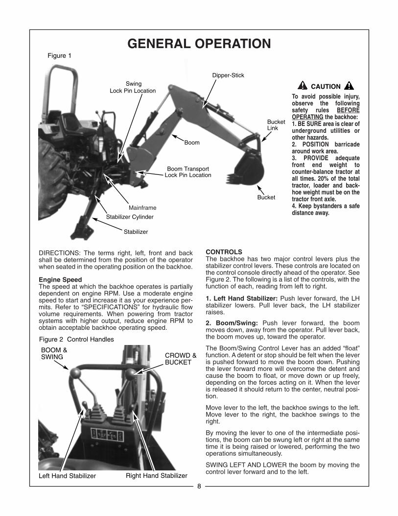
GENERAL OPERATION
CAUTION
To avoid possible injury,observe the followingsafety rules BEFOREOPERATING the backhoe:1. BE SURE area is clear ofunderground utilities orother hazards.2. POSITION barricadearound work area.3. PROVIDE adequatefront end weight tocounter-balance tractor atall times. 20% of the totaltractor, loader and back-hoe weight must be on thetractor front axle.4. Keep bystanders a safedistance away.
DIRECTIONS: The terms right, left, front and backshall be determined from the position of the operatorwhen seated in the operating position on the backhoe.
Engine SpeedThe speed at which the backhoe operates is partiallydependent on engine RPM. Use a moderate enginespeed to start and increase it as your experience per-mits. Refer to “SPECIFICATIONS” for hydraulic flowvolume requirements. When powering from tractorsystems with higher output, reduce engine RPM toobtain acceptable backhoe operating speed.
Boom
Dipper-Stick
Boom TransportLock Pin Location
Stabilizer
Bucket
BucketLink
Stabilizer Cylinder
Figure 1
CONTROLSThe backhoe has two major control levers plus thestabilizer control levers. These controls are located onthe control console directly ahead of the operator. SeeFigure 2. The following is a list of the controls, with thefunction of each, reading from left to right.
1. Left Hand Stabilizer: Push lever forward, the LHstabilizer lowers. Pull lever back, the LH stabilizerraises.
2. Boom/Swing: Push lever forward, the boommoves down, away from the operator. Pull lever back,the boom moves up, toward the operator.
The Boom/Swing Control Lever has an added “float”function. A detent or stop should be felt when the leveris pushed forward to move the boom down. Pushingthe lever forward more will overcome the detent andcause the boom to float, or move down or up freely,depending on the forces acting on it. When the leveris released it should return to the center, neutral posi-tion.
Move lever to the left, the backhoe swings to the left.Move lever to the right, the backhoe swings to theright.
By moving the lever to one of the intermediate posi-tions, the boom can be swung left or right at the sametime it is being raised or lowered, performing the twooperations simultaneously.
SWING LEFT AND LOWER the boom by moving thecontrol lever forward and to the left.
Mainframe
8
Left Hand Stabilizer
BOOM &SWING CROWD &
BUCKET
Right Hand Stabilizer
SwingLock Pin Location
Figure 2 Control Handles

SWING LEFT AND RAISE the boom by moving thecontrol lever back and to the left.
SWING RIGHT AND LOWER the boom by movingthe lever forward and to the right.
SWING RIGHT AND RAISE the boom by moving thelever back and to the right.
3. Crowd/Bucket: Push lever forward, the dipperstickmoves out, away from the operator. Pull lever back,the dipperstick moves in, toward the operator.
Move lever to left, the bucket curls in. Move lever toright, the bucket extends out.
By moving the lever to one of the intermediate posi-tions, the dipperstick can be extended or retracted atthe same time the bucket is being loaded or dumped.
EXTEND AND LOAD the bucket by moving the leverforward and to the left.
RETRACT AND LOAD the bucket by moving thelever back and to the left.
EXTEND AND DUMP the bucket by moving the leverforward and to the right.
RETRACT AND DUMP the bucket by moving thelever back and to the right.
The two operations of the boom/swing lever, com-bined with the two operations performed by thecrowd/bucket control lever, provide four simultaneousoperations from the two levers, keeping cycle time toa minimum.
4. Right Hand Stabilizer: Push lever forward, the RHstabilizer lowers. Pull lever back, the RH stabilizerraises.
OPERATING THE BACKHOE
To avoid possible injury, observe the followingsafety rules WHEN OPERATING the backhoe.
1. DISENGAGE safety lock pins as shown inFigure 3 before attempting to operate the back-hoe. Store lock pins in angled tubes located at therear right hand side of the backhoe below the footplatform. See Figure 3a.2. OPERATE from the backhoe operator’s seatonly.3. LOWER the stabilizers until the rear of the trac-tor is totally supported by them. NOTE: Rear tiresshould not come up off of the ground. See dia-gram on Page 11.4. DO NOT dig near the stabilizers.5. DO NOT touch overhead wires with any part ofthe backhoe.6. DO NOT attempt to raise the tractor off theground or move the tractor forward or backwardusing the backhoe dipperstick or bucket.7. DO NOT lose stability by swinging the bucketdownhill when positioned on a slope.8. DO NOT lower the backhoe boom using the“float” function. It will freefall, and could result ininjury to bystanders or damage to the backhoe.
9
CAUTION
In general, the direction of movement of a controllever corresponds to the movement of the operatingmember.
Figure 3 Safety Locks
Swing Lock Pin Boom Transport Lock Pin
Figure 3a
Lock Pins Storage Tubes
Smooth, light handling of the controls will result in themost efficient backhoe operation.
Operate the backhoe control levers to become famil-iar with their speed and movements. The enginespeed and the size of the hydraulic system will deter-mine the speed of cylinder operation. When poweringfrom tractor systems with higher output than required,reduce engine RPM to obtain acceptable backhoeoperating speed. If backhoe is to be mounted to atractor or to a skid steer loader with a hydraulic flowrate exceeding 12 gallons per minute (gpm), then thebackhoe must be equipped with a Flow Divider Kit.Refer to “Flow Divider Kit” section of this manual forassembly and installation instructions.
Swing the boom several times to practice controllingthe speed of swing. Do not operate the swing morethan 45° each way for the first few times, then gradu-ally increase the arc.
IMPORTANT: To avoid damage to the backhoe, donot slam unit into the rubber bumpers whenswinging the boom right or left.
The boom “float” function may be used during diggingto eliminate down pressure when cleaning the bottomof a trench. The primary purpose of the boom “float”function is to protect the operator from serious injury inthe event that the backhoe or tractor hitch would fail.
operator to save time in clearing the excavation.
This dual operation of controls will speed and simplifythe digging operation. Normally the two or moremovements will not be equal or even simultaneous,but as the pressure within the cylinders changes, andthe resistance on an operating member of the hoelessens, it will begin to move. It is balancing the forceof one member against the other.
NOTE: Actuating the bucket is the key to powerful dig-ging. Operating the crowd and bucket controls simul-taneously will insure a full bucket and prevent wastemotion and time.
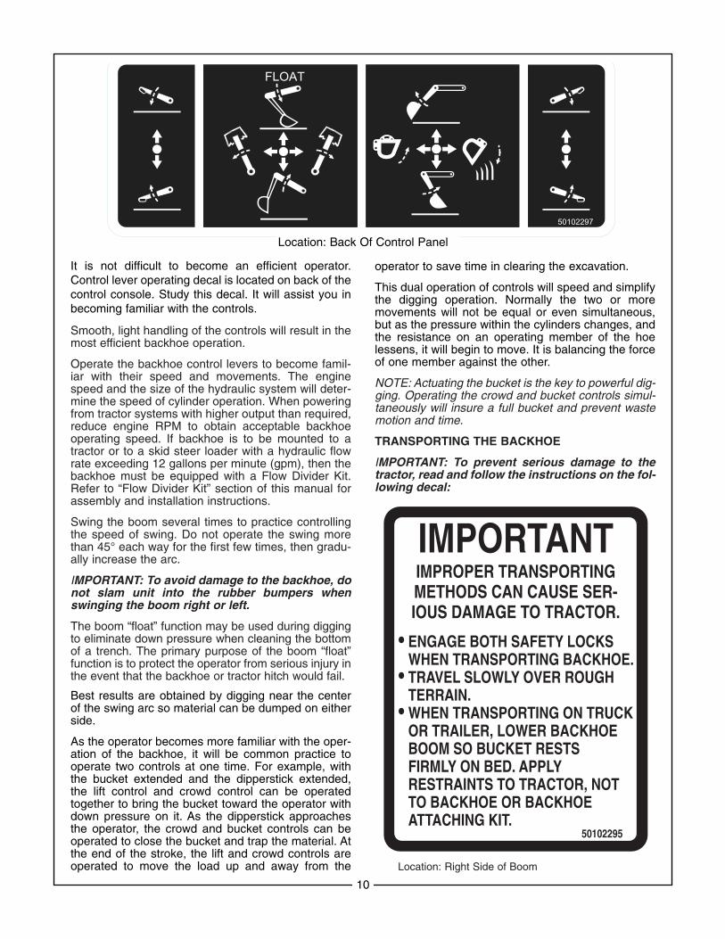
TRANSPORTING THE BACKHOE
IMPORTANT: To prevent serious damage to thetractor, read and follow the instructions on the fol-lowing decal:
Location: Right Side of Boom
10
It is not difficult to become an efficient operator.Control lever operating decal is located on back of thecontrol console. Study this decal. It will assist you inbecoming familiar with the controls.
Best results are obtained by digging near the centerof the swing arc so material can be dumped on eitherside.
As the operator becomes more familiar with the oper-ation of the backhoe, it will be common practice tooperate two controls at one time. For example, withthe bucket extended and the dipperstick extended,the lift control and crowd control can be operatedtogether to bring the bucket toward the operator withdown pressure on it. As the dipperstick approachesthe operator, the crowd and bucket controls can beoperated to close the bucket and trap the material. Atthe end of the stroke, the lift and crowd controls areoperated to move the load up and away from the
Location: Back Of Control Panel
IMPORTANTIMPROPER TRANSPORTINGMETHODS CAN CAUSE SER-IOUS DAMAGE TO TRACTOR.
• ENGAGE BOTH SAFETY LOCKSWHEN TRANSPORTING BACKHOE.
• TRAVEL SLOWLY OVER ROUGHTERRAIN.
• WHEN TRANSPORTING ON TRUCKOR TRAILER, LOWER BACKHOEBOOM SO BUCKET RESTSFIRMLY ON BED. APPLYRESTRAINTS TO TRACTOR, NOTTO BACKHOE OR BACKHOEATTACHING KIT.
50102295
CAUTIONTo avoid possible injury, observe the following safetyrules when transporting the backhoe:
1. ALWAYS engage safety locks as shown on Figs. 1and 3 when transporting backhoe.
2. TRAVEL SLOWLY over rough terrain, on hillsides,and around curves to prevent tipping.
3. DO NOT drive the tractor near the edge of a ditchor excavation.
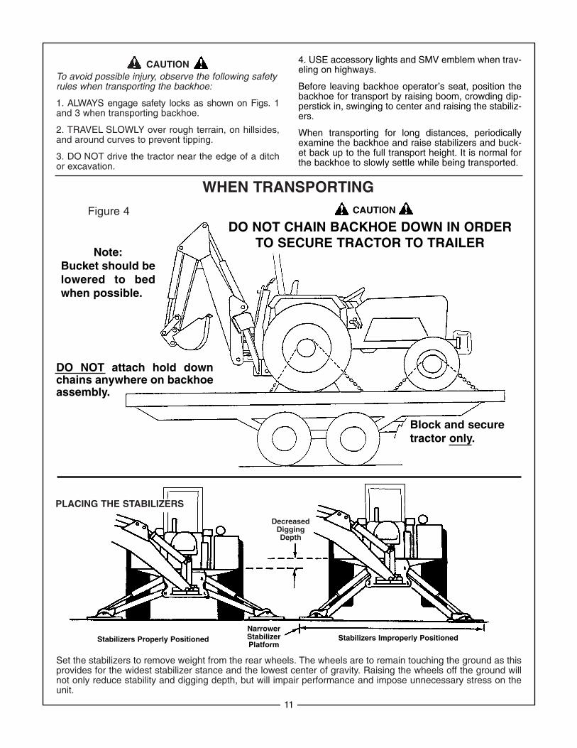
4. USE accessory lights and SMV emblem when trav-eling on highways.
Before leaving backhoe operator’s seat, position thebackhoe for transport by raising boom, crowding dip-perstick in, swinging to center and raising the stabiliz-ers.
When transporting for long distances, periodicallyexamine the backhoe and raise stabilizers and buck-et back up to the full transport height. It is normal forthe backhoe to slowly settle while being transported.
PLACING THE STABILIZERS
DecreasedDiggingDepth
NarrowerStabilizerPlatform
Stabilizers Improperly PositionedStabilizers Properly Positioned
Set the stabilizers to remove weight from the rear wheels. The wheels are to remain touching the ground as thisprovides for the widest stabilizer stance and the lowest center of gravity. Raising the wheels off the ground willnot only reduce stability and digging depth, but will impair performance and impose unnecessary stress on theunit.
11
WHEN TRANSPORTING
Note:Bucket should belowered to bedwhen possible.
DO NOT attach hold downchains anywhere on backhoeassembly.
Block and securetractor only.
DO NOT CHAIN BACKHOE DOWN IN ORDERTO SECURE TRACTOR TO TRAILER
CAUTIONFigure 4
General Operations
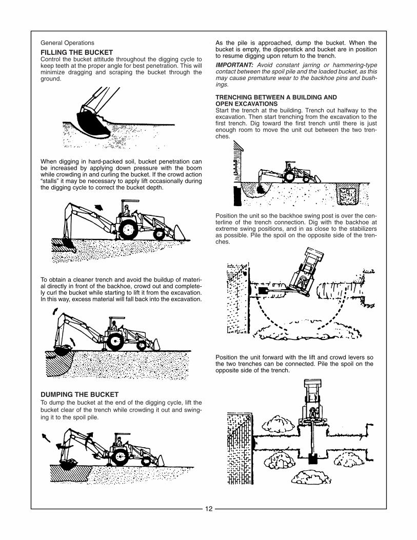
FILLING THE BUCKETControl the bucket attitude throughout the digging cycle tokeep teeth at the proper angle for best penetration. This willminimize dragging and scraping the bucket through theground.
When digging in hard-packed soil, bucket penetration canbe increased by applying down pressure with the boomwhile crowding in and curling the bucket. If the crowd action“stalls” it may be necessary to apply lift occasionally duringthe digging cycle to correct the bucket depth.
To obtain a cleaner trench and avoid the buildup of materi-al directly in front of the backhoe, crowd out and complete-ly curl the bucket while starting to lift it from the excavation.In this way, excess material will fall back into the excavation.
DUMPING THE BUCKETTo dump the bucket at the end of the digging cycle, lift thebucket clear of the trench while crowding it out and swing-ing it to the spoil pile.
As the pile is approached, dump the bucket. When thebucket is empty, the dipperstick and bucket are in positionto resume digging upon return to the trench.
IMPORTANT: Avoid constant jarring or hammering-typecontact between the spoil pile and the loaded bucket, as thismay cause premature wear to the backhoe pins and bush-ings.
TRENCHING BETWEEN A BUILDING ANDOPEN EXCAVATIONSStart the trench at the building. Trench out halfway to theexcavation. Then start trenching from the excavation to thefirst trench. Dig toward the first trench until there is justenough room to move the unit out between the two tren-ches.
Position the unit so the backhoe swing post is over the cen-terline of the trench connection. Dig with the backhoe atextreme swing positions, and in as close to the stabilizersas possible. Pile the spoil on the opposite side of the tren-ches.
Position the unit forward with the lift and crowd levers sothe two trenches can be connected. Pile the spoil on theopposite side of the trench.
12
General Operations
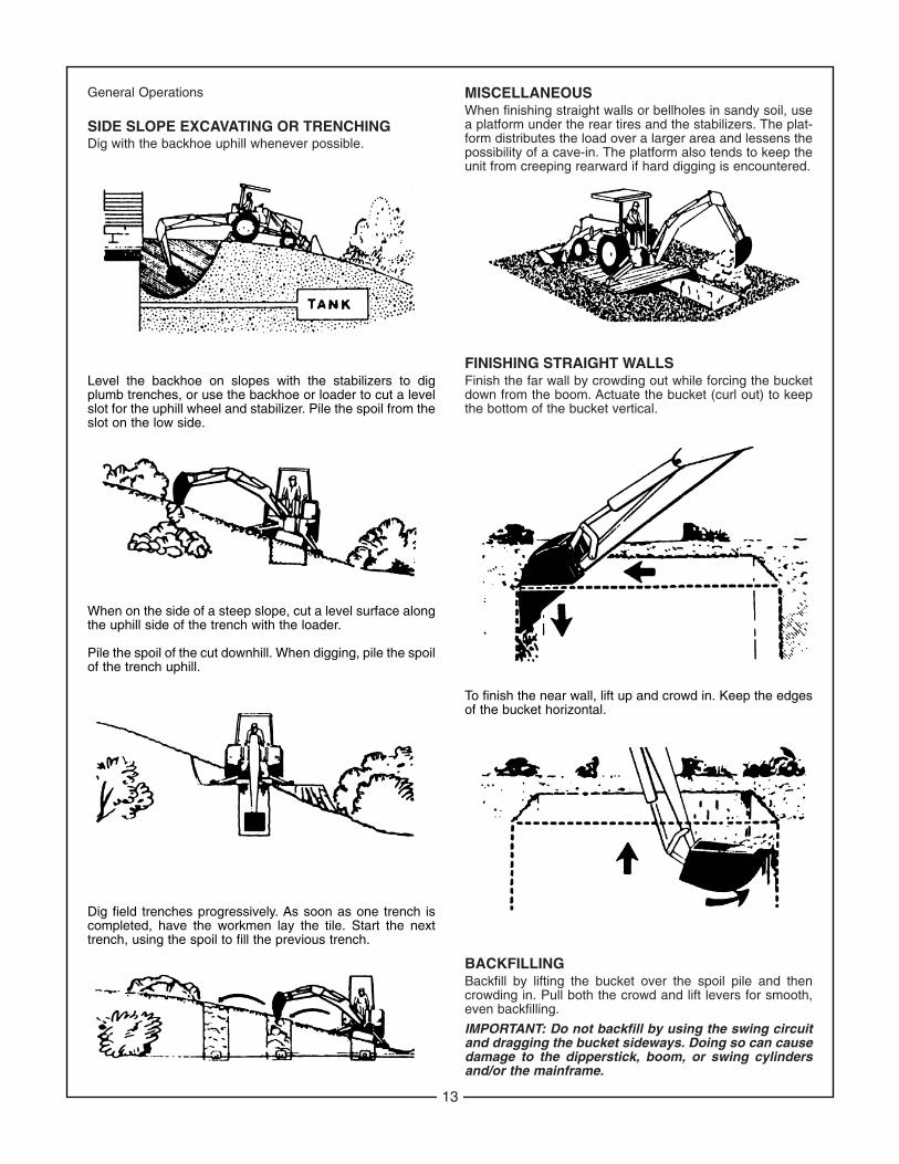
SIDE SLOPE EXCAVATING OR TRENCHINGDig with the backhoe uphill whenever possible.
Level the backhoe on slopes with the stabilizers to digplumb trenches, or use the backhoe or loader to cut a levelslot for the uphill wheel and stabilizer. Pile the spoil from theslot on the low side.
When on the side of a steep slope, cut a level surface alongthe uphill side of the trench with the loader.
Pile the spoil of the cut downhill. When digging, pile the spoilof the trench uphill.
Dig field trenches progressively. As soon as one trench iscompleted, have the workmen lay the tile. Start the nexttrench, using the spoil to fill the previous trench.
MISCELLANEOUSWhen finishing straight walls or bellholes in sandy soil, usea platform under the rear tires and the stabilizers. The plat-form distributes the load over a larger area and lessens thepossibility of a cave-in. The platform also tends to keep theunit from creeping rearward if hard digging is encountered.
FINISHING STRAIGHT WALLSFinish the far wall by crowding out while forcing the bucketdown from the boom. Actuate the bucket (curl out) to keepthe bottom of the bucket vertical.
To finish the near wall, lift up and crowd in. Keep the edgesof the bucket horizontal.
BACKFILLINGBackfill by lifting the bucket over the spoil pile and thencrowding in. Pull both the crowd and lift levers for smooth,even backfilling.
IMPORTANT: Do not backfill by using the swing circuitand dragging the bucket sideways. Doing so can causedamage to the dipperstick, boom, or swing cylindersand/or the mainframe.
13
fully several times to purge the system of air.Hydraulic System HosesOil leaks in the pressure side of the system can belocated by carefully inspecting the external area of thehoses and fittings.
Check the return side of the system for leaks byexamining the oil in the reservoir. If air is being drawninto the system, the oil will contain air bubbles andappear to foam.
When tightening connections, always use twowrenches.
IMPORTANT: Do not over-tighten fittings. Make themjust tight enough to eliminate leaks.
NEVER use teflon tape on pipe thread fittings.Always use a paste-type sealer.Hoses on any backhoe are very severely worked andwill fail in time. Examine them regularly and replaceany that show signs of failure. Pay careful attention tothe routing of hoses so they can move fully and freelywithout kinking, and cannot be pinched or cut by anypart of the backhoe.
Hydraulic System Reservoir On PTO pump systems, maintain the reservoir oil at theproper level by looking at the dipstick. Thedipstick/breather cap is located directly behind the rightside of the foot platform on the backhoe. When check-ing oil level, the backhoe should be extended to fullreach with the bucket rolled back and resting on theground. All cylinders are retracted except for the boomcylinder. Do not overfill; oil may be forced out of thebreather cap.Fill with:
SAE 10W40 engine oil with API “SF/SG” classifica-tion in northern climates.
SAE 40W engine oil with API “SF/SG” classification in southern climates.
Change oil every 200 hours or more often if neces-sary. To change oil, extend backhoe to full reach withbucket rolled back and resting on ground. Turn offtractor PTO and shut down tractor engine. Unseatbreather cap from fill tube and remove drain plug fromleft rear underside of hydraulic reservoir using 1/4”hex wrench. Drain oil from reservoir and replace drainplug. Refill reservoir with 7 gallons of fresh oil fol-lowing guidelines listed above for proper oilselection. Reseat breather cap and start engine andPTO. After cycling all backhoe functions several timesto remove any air from hydraulic system, check oillevel in reservoir with backhoe extended to full reachand bucket rolled back and resting on ground. If oillevel on dipstick is below “ADD” line, add enough oilto bring level up to “FULL” line. DO NOT overfill reser-voir or oil may be forced out through breather cap dur-ing backhoe operation.
If the tractor system supplies the hydraulic power, ser-vice according to the tractor instruction manual.
14
SERVICECAUTION
To avoid possible injury, observe the followingsafety rules WHEN SERVICING the backhoe:
1. ENGAGE safety locks as shown in Figures 1 & 3before servicing the backhoe.
2. DO NOT oil, grease or adjust the backhoe while itis in motion.
3. DO NOT change any backhoe relief valve settings.They are factory set for best performance and safety.
4. ESCAPING FLUID underpressure can have sufficientforce to penetrate the skin andcause serious injury. Be sureto relieve all pressure beforedisconnecting lines. Be sureall connections are tight andthat lines, pipes and hoses are not damaged beforeapplying pressure to the system.
5. FLUID ESCAPING from a very small hole can bealmost invisible. Use a small piece of cardboard orwood - not your hands - to search for suspected leaks.
6. SEE A DOCTOR AT ONCE if injured by escapingfluid. Serious infection or gangrene can develop ifproper medical treatment is not administered immedi-ately.
7. PROTECT YOUR EYES - Wear safety glasses.Guard against injury when driving connecting pins orperforming any repair in which particles can chip fromwork piece or striking tool.
BEGINNING OF SEASONRemove all protective coverings.
Check hydraulic hoses for deterioration and replace,if necessary.
Lubricate all grease fittings and oil handle linkages.
Check hydraulic system for loss of fluid and, if neces-sary, fill to proper level.
Tighten all loose bolts, nuts and setscrews.
Inspect bucket teeth and, if necessary, sharpen orreplace them.
Operate the backhoe slowly for a short time beforeplacing the unit under full load.
Bleeding Backhoe Hydraulic SystemIf the hydraulic hoses have been disconnected fromthe backhoe or tractor, all trapped air must beremoved after the hoses are connected. Start tractorengine and operate backhoe through all movements
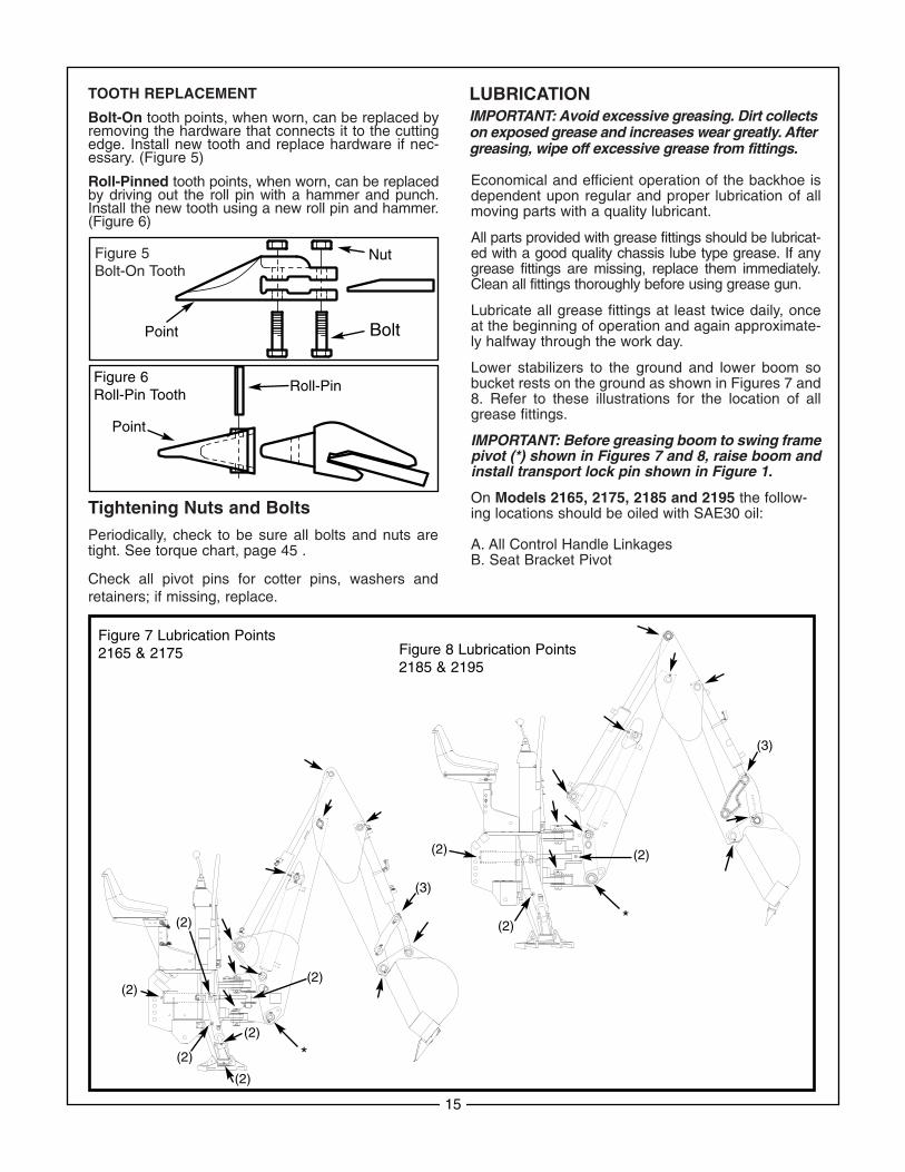
TOOTH REPLACEMENT
Bolt-On tooth points, when worn, can be replaced byremoving the hardware that connects it to the cuttingedge. Install new tooth and replace hardware if nec-essary. (Figure 5)
Roll-Pinned tooth points, when worn, can be replacedby driving out the roll pin with a hammer and punch.Install the new tooth using a new roll pin and hammer.(Figure 6)
Economical and efficient operation of the backhoe isdependent upon regular and proper lubrication of allmoving parts with a quality lubricant.
All parts provided with grease fittings should be lubricat-ed with a good quality chassis lube type grease. If anygrease fittings are missing, replace them immediately.Clean all fittings thoroughly before using grease gun.
Lubricate all grease fittings at least twice daily, onceat the beginning of operation and again approximate-ly halfway through the work day.
Lower stabilizers to the ground and lower boom sobucket rests on the ground as shown in Figures 7 and8. Refer to these illustrations for the location of allgrease fittings.
IMPORTANT: Before greasing boom to swing framepivot (*) shown in Figures 7 and 8, raise boom andinstall transport lock pin shown in Figure 1.
On Models 2165, 2175, 2185 and 2195 the follow-ing locations should be oiled with SAE30 oil:
A. All Control Handle LinkagesB. Seat Bracket Pivot
15
Figure 6Roll-Pin Tooth
LUBRICATIONIMPORTANT: Avoid excessive greasing. Dirt collectson exposed grease and increases wear greatly. Aftergreasing, wipe off excessive grease from fittings.
Figure 5Bolt-On Tooth
Nut
BoltPoint
Point
Roll-Pin
Figure 7 Lubrication Points2165 & 2175
Tightening Nuts and BoltsPeriodically, check to be sure all bolts and nuts aretight. See torque chart, page 45 .
Check all pivot pins for cotter pins, washers andretainers; if missing, replace.
Figure 8 Lubrication Points2185 & 2195
(3)
(3)
(2) (2)
(2)(2)
(2)
(2)
(2)
(2)
(2)
*
*
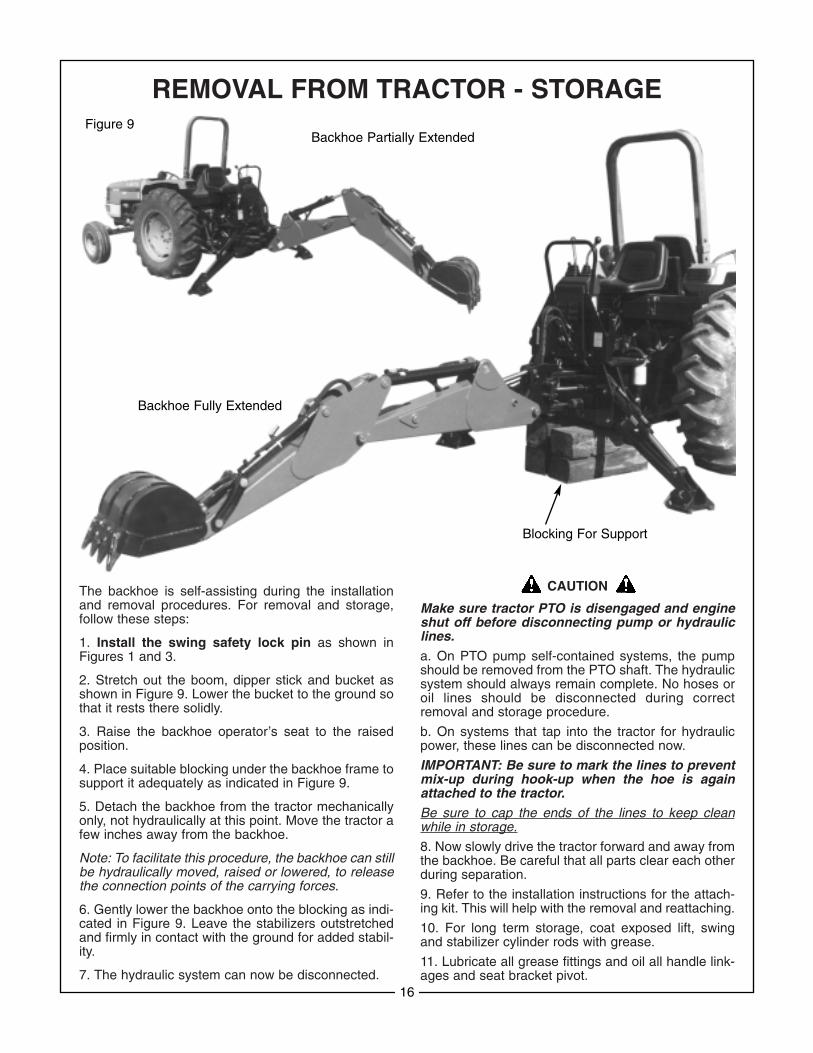
REMOVAL FROM TRACTOR - STORAGE
The backhoe is self-assisting during the installationand removal procedures. For removal and storage,follow these steps:
1. Install the swing safety lock pin as shown inFigures 1 and 3.
2. Stretch out the boom, dipper stick and bucket asshown in Figure 9. Lower the bucket to the ground sothat it rests there solidly.
3. Raise the backhoe operator’s seat to the raisedposition.
4. Place suitable blocking under the backhoe frame tosupport it adequately as indicated in Figure 9.
5. Detach the backhoe from the tractor mechanicallyonly, not hydraulically at this point. Move the tractor afew inches away from the backhoe.
Note: To facilitate this procedure, the backhoe can stillbe hydraulically moved, raised or lowered, to releasethe connection points of the carrying forces.
6. Gently lower the backhoe onto the blocking as indi-cated in Figure 9. Leave the stabilizers outstretchedand firmly in contact with the ground for added stabil-ity.
7. The hydraulic system can now be disconnected.
CAUTION
Make sure tractor PTO is disengaged and engineshut off before disconnecting pump or hydrauliclines.a. On PTO pump self-contained systems, the pumpshould be removed from the PTO shaft. The hydraulicsystem should always remain complete. No hoses oroil lines should be disconnected during correctremoval and storage procedure.
b. On systems that tap into the tractor for hydraulicpower, these lines can be disconnected now.
IMPORTANT: Be sure to mark the lines to preventmix-up during hook-up when the hoe is againattached to the tractor.Be sure to cap the ends of the lines to keep cleanwhile in storage.
8. Now slowly drive the tractor forward and away fromthe backhoe. Be careful that all parts clear each otherduring separation.
9. Refer to the installation instructions for the attach-ing kit. This will help with the removal and reattaching.
10. For long term storage, coat exposed lift, swingand stabilizer cylinder rods with grease.
11. Lubricate all grease fittings and oil all handle link-ages and seat bracket pivot.
Backhoe Partially Extended
16
Figure 9
Backhoe Fully Extended
Blocking For Support
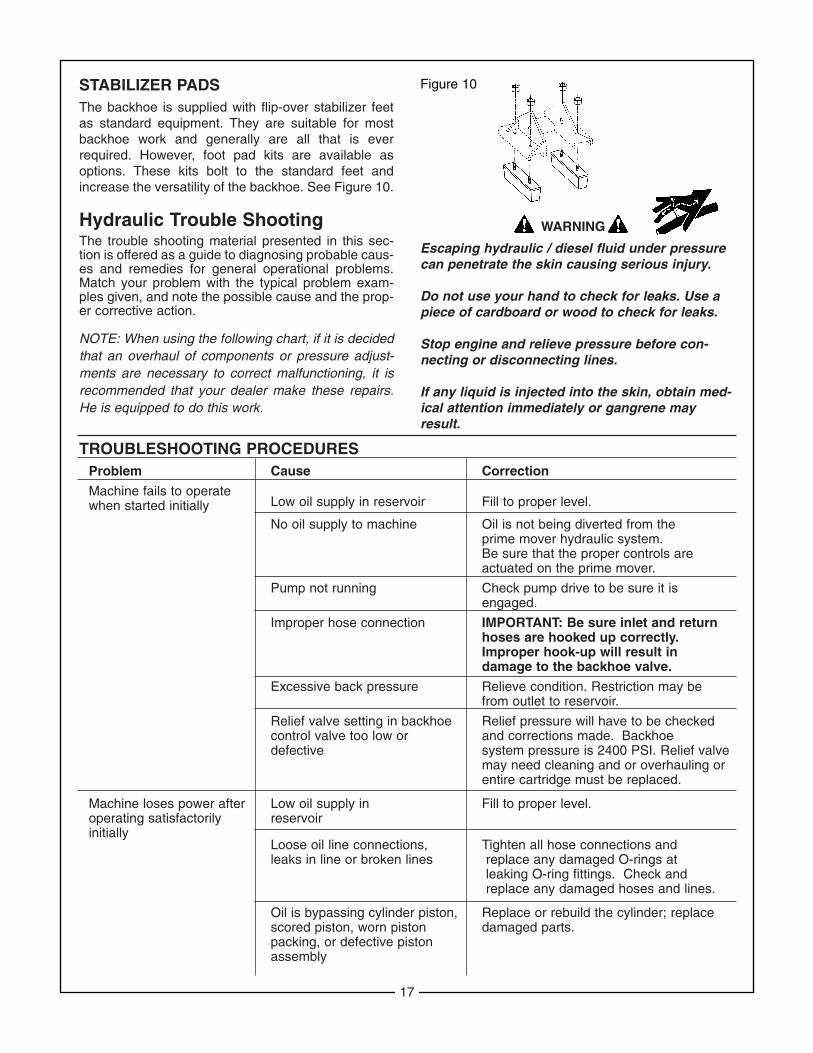
STABILIZER PADSThe backhoe is supplied with flip-over stabilizer feetas standard equipment. They are suitable for mostbackhoe work and generally are all that is everrequired. However, foot pad kits are available asoptions. These kits bolt to the standard feet andincrease the versatility of the backhoe. See Figure 10.
Hydraulic Trouble ShootingThe trouble shooting material presented in this sec-tion is offered as a guide to diagnosing probable caus-es and remedies for general operational problems.Match your problem with the typical problem exam-ples given, and note the possible cause and the prop-er corrective action.
NOTE: When using the following chart, if it is decidedthat an overhaul of components or pressure adjust-ments are necessary to correct malfunctioning, it isrecommended that your dealer make these repairs.He is equipped to do this work.
17
Figure 10
WARNING
Escaping hydraulic / diesel fluid under pressurecan penetrate the skin causing serious injury.
Do not use your hand to check for leaks. Use apiece of cardboard or wood to check for leaks.
Stop engine and relieve pressure before con-necting or disconnecting lines.
If any liquid is injected into the skin, obtain med-ical attention immediately or gangrene mayresult.
TROUBLESHOOTING PROCEDURESProblem Cause Correction
Machine fails to operatewhen started initially Low oil supply in reservoir Fill to proper level.
No oil supply to machine Oil is not being diverted from the prime mover hydraulic system. Be sure that the proper controls are actuated on the prime mover.
Pump not running Check pump drive to be sure it isengaged.
Improper hose connection IMPORTANT: Be sure inlet and returnhoses are hooked up correctly.Improper hook-up will result indamage to the backhoe valve.
Excessive back pressure Relieve condition. Restriction may befrom outlet to reservoir.
Relief valve setting in backhoe Relief pressure will have to be checkedcontrol valve too low or and corrections made. Backhoedefective system pressure is 2400 PSI. Relief valve
may need cleaning and or overhauling orentire cartridge must be replaced.
Machine loses power after Low oil supply in Fill to proper level.operating satisfactorily reservoirinitially
Loose oil line connections, Tighten all hose connections andleaks in line or broken lines replace any damaged O-rings at
leaking O-ring fittings. Check andreplace any damaged hoses and lines.
Oil is bypassing cylinder piston, Replace or rebuild the cylinder; replacescored piston, worn piston damaged parts.packing, or defective pistonassembly
18
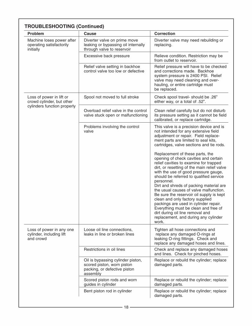
TROUBLESHOOTING (Continued)Problem Cause Correction
Machine loses power after Diverter valve on prime move Diverter valve may need rebuilding oroperating satisfactorily leaking or bypassing oil internally replacing.initially through valve to reservoir
Excessive back pressure Relieve condition. Restriction may be from outlet to reservoir.
Relief valve setting in backhoe Relief pressure will have to be checkedcontrol valve too low or defective and corrections made. Backhoe
system pressure is 2400 PSI. Relief valve may need cleaning and over-hauling, or entire cartridge must be replaced.
Loss of power in lift or Spool not moved to full stroke Check spool travel- should be .26” crowd cylinder, but other either way, or a total of .52”.cylinders function properly
Overload relief valve in the control Clean relief carefully but do not disturbvalve stuck open or malfunctioning its pressure setting as it cannot be field
calibrated, or replace cartridge.
Problems involving the control This valve is a precision device and isvalve not intended for any extensive field
adjustment or repair. Field replace-ment parts are limited to seal kits,cartridges, valve sections and tie rods.
Replacement of these parts, theopening of check cavities and certainrelief cavities to examine for trappeddirt, or resetting of the main relief valvewith the use of good pressure gauge,should be referred to qualified servicepersonnel.Dirt and shreds of packing material arethe usual causes of valve malfunction.Be sure the reservoir oil supply is keptclean and only factory suppliedpackings are used in cylinder repair.Everything must be clean and free ofdirt during oil line removal andreplacement, and during any cylinderwork.
Loss of power in any one Loose oil line connections, Tighten all hose connections andcylinder, including lift leaks in line or broken lines replace any damaged O-rings at and crowd leaking O-ring fittings. Check and
replace any damaged hoses and lines.
Restrictions in oil lines Check and replace any damaged hosesand lines. Check for pinched hoses.
Oil is bypassing cylinder piston, Replace or rebuild the cylinder; replacescored piston, worn piston damaged parts.packing, or defective pistonassembly
Scored piston rods and worn Replace or rebuild the cylinder; replaceguides in cylinder damaged parts.
Bent piston rod in cylinder Replace or rebuild the cylinder; replacedamaged parts.
19
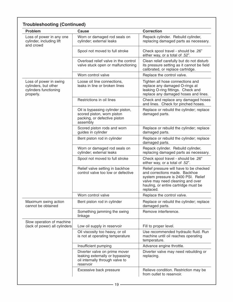
Troubleshooting (Continued)Problem Cause Correction
Loss of power in any one Worn or damaged rod seals on Repack cylinder. Rebuild cylinder,cylinder, including lift cylinder; external leaks replacing damaged parts as necessary.and crowd
Spool not moved to full stroke Check spool travel - should be .26” either way, or a total of .52”.
Overload relief valve in the control Clean relief carefully but do not disturbvalve stuck open or malfunctioning its pressure setting as it cannot be field
calibrated, or replace cartridge.
Worn control valve Replace the control valve.
Loss of power in swing Loose oil line connections, Tighten all hose connections andcylinders, but other leaks in line or broken lines replace any damaged O-rings atcylinders functioning leaking O-ring fittings. Check andproperly. replace any damaged hoses and lines.
Restrictions in oil lines Check and replace any damaged hosesand lines. Check for pinched hoses.
Oil is bypassing cylinder piston, Replace or rebuild the cylinder; replacescored piston, worn piston damaged parts.packing, or defective pistonassembly
Scored piston rods and worn Replace or rebuild the cylinder; replaceguides in cylinder damaged parts.
Bent piston rod in cylinder Replace or rebuild the cylinder; replacedamaged parts.
Worn or damaged rod seals on Repack cylinder. Rebuild cylinder,cylinder; external leaks replacing damaged parts as necessary.
Spool not moved to full stroke Check spool travel - should be .26” either way, or a total of .52”.
Relief valve setting in backhoe Relief pressure will have to be checkedcontrol valve too low or defective and corrections made. Backhoe
system pressure is 2400 PSI. Relief valve may need cleaning and overhauling, or entire cartridge must be replaced.
Worn control valve Replace the control valve.
Maximum swing action Bent piston rod in cylinder Replace or rebuild the cylinder; replacecannot be obtained damaged parts.
Something jamming the swing Remove interference.linkage
Slow operation of machine(lack of power) all cylinders Low oil supply in reservoir Fill to proper level.
Oil viscosity too heavy, or oil Use recommended hydraulic fluid. Runis not at operating temperature machine until oil reaches operating
temperature.
Insufficient pumping Advance engine throttle.
Diverter valve on prime mover Diverter valve may need rebuilding orleaking externally or bypassing replacing.oil internally through valve toreservoir
Excessive back pressure Relieve condition. Restriction may be from outlet to reservoir.

20
Troubleshooting (Continued)Problem Cause Correction
Slow operation of machine Relief valve setting in backhoe Relief pressure will have to be checked(lack of power) all cylinders control valve too low or defective and corrections made. Backhoe
system pressure is 2400 PSI. Relief valve may need cleaning and over-hauling, or entire cartridge must be replaced.
Spongy or jerking action Low oil supply in reservoir Fill to proper level.of cylinders and/or noisyoperation Air in system Bleed all circuits of air by operating
machine at maximum oil flow andthrough full movements.
Oil viscosity too heavy, or Use recommended hydralic fluid. Run oil is not at operating machine until oil reaches operatingtemperature temperature.
Pump not running Check pump drive to be sure it is engaged.
Lift, crowd or bucket Damaged or worn spool Replace spool end seals.cylinders drop under load sealswhen control spools shifted from neutral Problems involving the control This valve is a precision device and is
valve not intended for any extensive fieldadjustment or repair. Field replace-ment parts are limited to seal kits,cartridges, valve sections and tie rods.
Replacement of these parts, theopening of check cavities and certainrelief cavities to examine for trappeddirt, or resetting of the main relief valvewith the use of good pressure gauge,should be referred to qualified servicepersonnel.Dirt and shreds of packing material arethe usual causes of valve malfunction.Be sure the reservoir oil supply is keptclean and only factory suppliedpackings are used in cylinder repair.Everything must be clean and free ofdirt during the oil line removal andreplacement, and during any cylinderwork.
Load drops or settles Loose oil line connections, Tighten all hose connections andleaks in line or broken lines replace any damaged O-rings at
leaking O-ring fittings. Check andreplace any damaged hoses and lines.
Oil is bypassing cylinder piston, Replace or rebuild the cylinder; replacescored piston, worn piston damaged parts.packing, or defective pistonassembly
Worn or damaged rod seals on Repack cylinder. Rebuild cylinder,cylinder; external leaks replacing damaged parts as necessary.
Worn control valve Replace the control valve.
Damaged or worn spool seals Replace spool end seals.
21
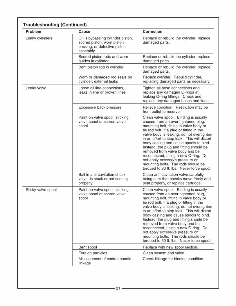
Troubleshooting (Continued)Problem Cause Correction
Leaky cylinders Oil is bypassing cylinder piston, Replace or rebuild the cylinder; replacescored piston, worn piston damaged parts.packing, or defective pistonassembly
Scored piston rods and worn Replace or rebuild the cylinder; replaceguides in cylinder damaged parts.
Bent piston rod in cylinder Replace or rebuild the cylinder; replacedamaged parts.
Worn or damaged rod seals on Repack cylinder. Rebuild cylinder,cylinder; external leaks replacing damaged parts as necessary.
Leaky valve Loose oil line connections, Tighten all hose connections andleaks in line or broken lines replace any damaged O-rings at
leaking O-ring fittings. Check andreplace any damaged hoses and lines.
Excessive back pressure Relieve condition. Restriction may be from outlet to reservoir.
Paint on valve spool; sticking Clean valve spool. Binding is usuallyvalve spool or scored valve caused from an over tightened plug,spool mounting bolt, fitting in valve body or
tie rod bolt. If a plug or fitting in the valve body is leaking, do not overtighten in an effort to stop leak. This will distortbody casting and cause spools to bind.Instead, the plug and fitting should be removed from valve body and be reconnected, using a new O-ring. Do not apply excessive pressure on mounting bolts. The rods should be torqued to 30 ft. lbs. Never force spool.
Ball in anti-cavitation check Clean anti-cavitation valve carefully,valve is stuck or not seating being sure that checks move freely andproperly. seat properly, or replace cartridge.
Sticky valve spool Paint on valve spool; sticking Clean valve spool. Binding is usuallyvalve spool or scored valve caused from an over tightened plug,spool mounting bolt, fitting in valve body or
tie rod bolt. If a plug or fitting in the valve body is leaking, do not overtighten in an effort to stop leak. This will distortbody casting and cause spools to bind.Instead, the plug and fitting should be removed from valve body and be reconnected, using a new O-ring. Do not apply excessive pressure on mounting bolts. The rods should be torqued to 30 ft. lbs. Never force spool.
Bent spool Replace with new spool section.
Foreign particles Clean system and valve.
Misalignment of control handle Check linkage for binding condition.linkage
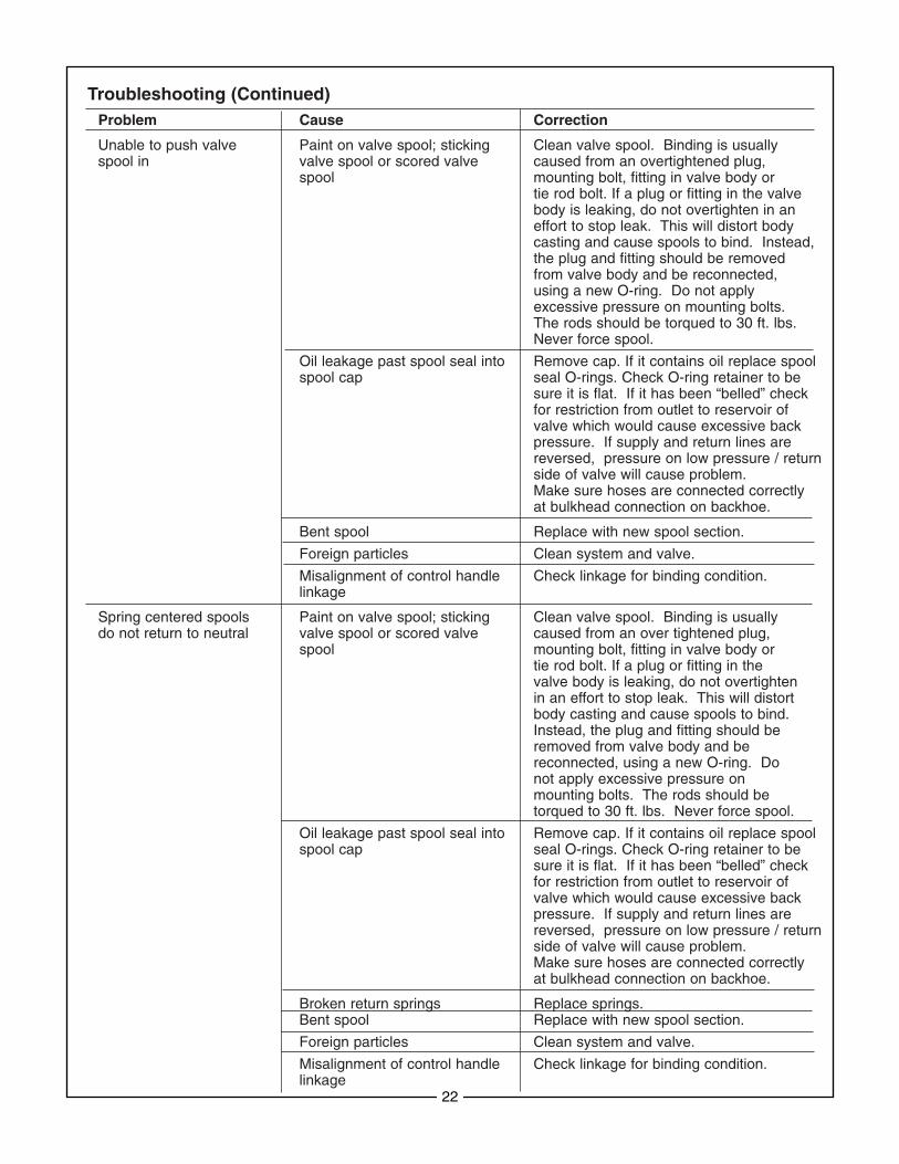
Troubleshooting (Continued)Problem Cause Correction
Unable to push valve Paint on valve spool; sticking Clean valve spool. Binding is usually spool in valve spool or scored valve caused from an overtightened plug,
spool mounting bolt, fitting in valve body ortie rod bolt. If a plug or fitting in the valvebody is leaking, do not overtighten in aneffort to stop leak. This will distort bodycasting and cause spools to bind. Instead,the plug and fitting should be removedfrom valve body and be reconnected,using a new O-ring. Do not apply excessive pressure on mounting bolts.The rods should be torqued to 30 ft. lbs.Never force spool.
Oil leakage past spool seal into Remove cap. If it contains oil replace spool spool cap seal O-rings. Check O-ring retainer to be
sure it is flat. If it has been “belled” check for restriction from outlet to reservoir of valve which would cause excessive back pressure. If supply and return lines are reversed, pressure on low pressure / return side of valve will cause problem. Make sure hoses are connected correctly at bulkhead connection on backhoe.
Bent spool Replace with new spool section.
Foreign particles Clean system and valve.
Misalignment of control handle Check linkage for binding condition.linkage
Spring centered spools Paint on valve spool; sticking Clean valve spool. Binding is usuallydo not return to neutral valve spool or scored valve caused from an over tightened plug,
spool mounting bolt, fitting in valve body ortie rod bolt. If a plug or fitting in the valve body is leaking, do not overtighten in an effort to stop leak. This will distortbody casting and cause spools to bind.Instead, the plug and fitting should be removed from valve body and be reconnected, using a new O-ring. Do not apply excessive pressure on mounting bolts. The rods should be torqued to 30 ft. lbs. Never force spool.
Oil leakage past spool seal into Remove cap. If it contains oil replace spoolspool cap seal O-rings. Check O-ring retainer to be
sure it is flat. If it has been “belled” check for restriction from outlet to reservoir of valve which would cause excessive back pressure. If supply and return lines are reversed, pressure on low pressure / return side of valve will cause problem. Make sure hoses are connected correctly at bulkhead connection on backhoe.
Broken return springs Replace springs.Bent spool Replace with new spool section.
Foreign particles Clean system and valve.
Misalignment of control handle Check linkage for binding condition.linkage
22
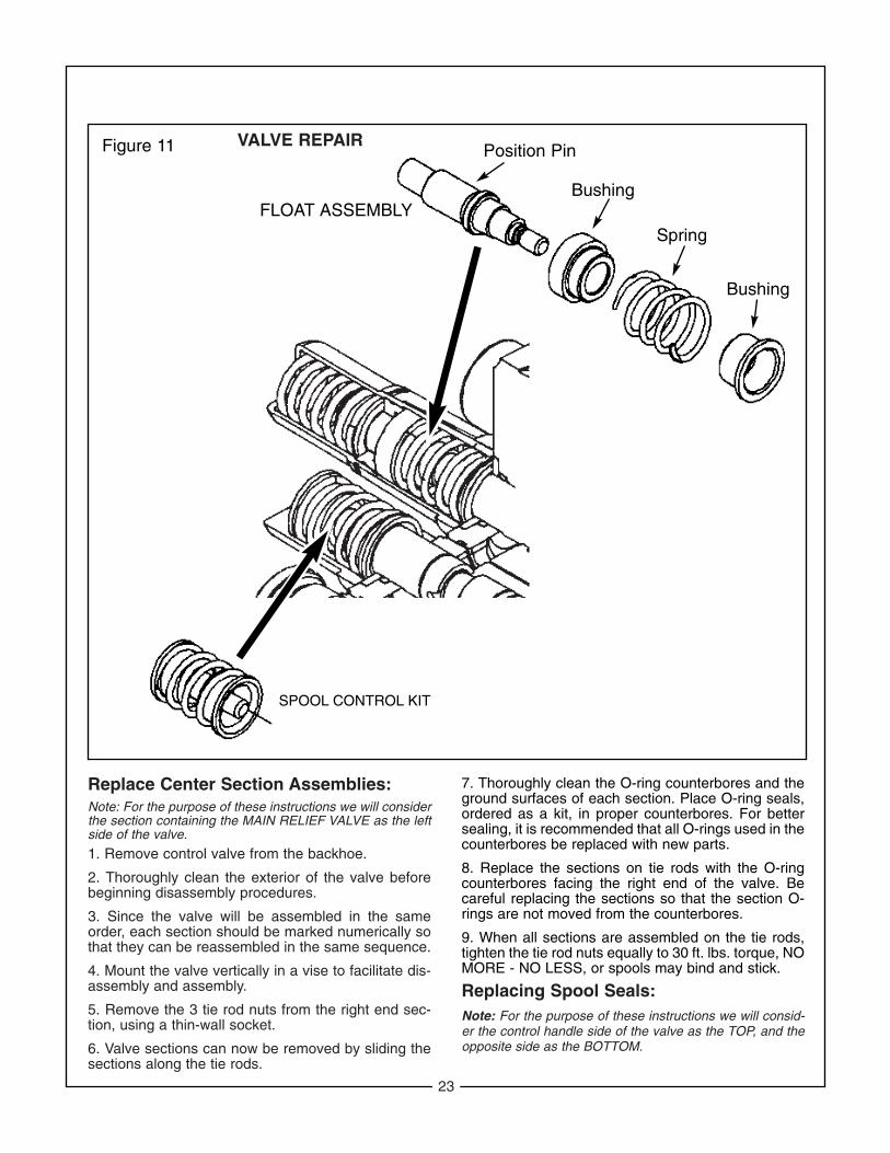
Replace Center Section Assemblies:Note: For the purpose of these instructions we will considerthe section containing the MAIN RELIEF VALVE as the leftside of the valve.
1. Remove control valve from the backhoe.
2. Thoroughly clean the exterior of the valve beforebeginning disassembly procedures.
3. Since the valve will be assembled in the sameorder, each section should be marked numerically sothat they can be reassembled in the same sequence.
4. Mount the valve vertically in a vise to facilitate dis-assembly and assembly.
5. Remove the 3 tie rod nuts from the right end sec-tion, using a thin-wall socket.
6. Valve sections can now be removed by sliding thesections along the tie rods.
7. Thoroughly clean the O-ring counterbores and theground surfaces of each section. Place O-ring seals,ordered as a kit, in proper counterbores. For bettersealing, it is recommended that all O-rings used in thecounterbores be replaced with new parts.
8. Replace the sections on tie rods with the O-ringcounterbores facing the right end of the valve. Becareful replacing the sections so that the section O-rings are not moved from the counterbores.
9. When all sections are assembled on the tie rods,tighten the tie rod nuts equally to 30 ft. lbs. torque, NOMORE - NO LESS, or spools may bind and stick.
Replacing Spool Seals:Note: For the purpose of these instructions we will consid-er the control handle side of the valve as the TOP, and theopposite side as the BOTTOM.
23
FLOAT ASSEMBLY
Figure 11
SPOOL CONTROL KIT
Position Pin
Bushing
Spring
Bushing
VALVE REPAIR
24
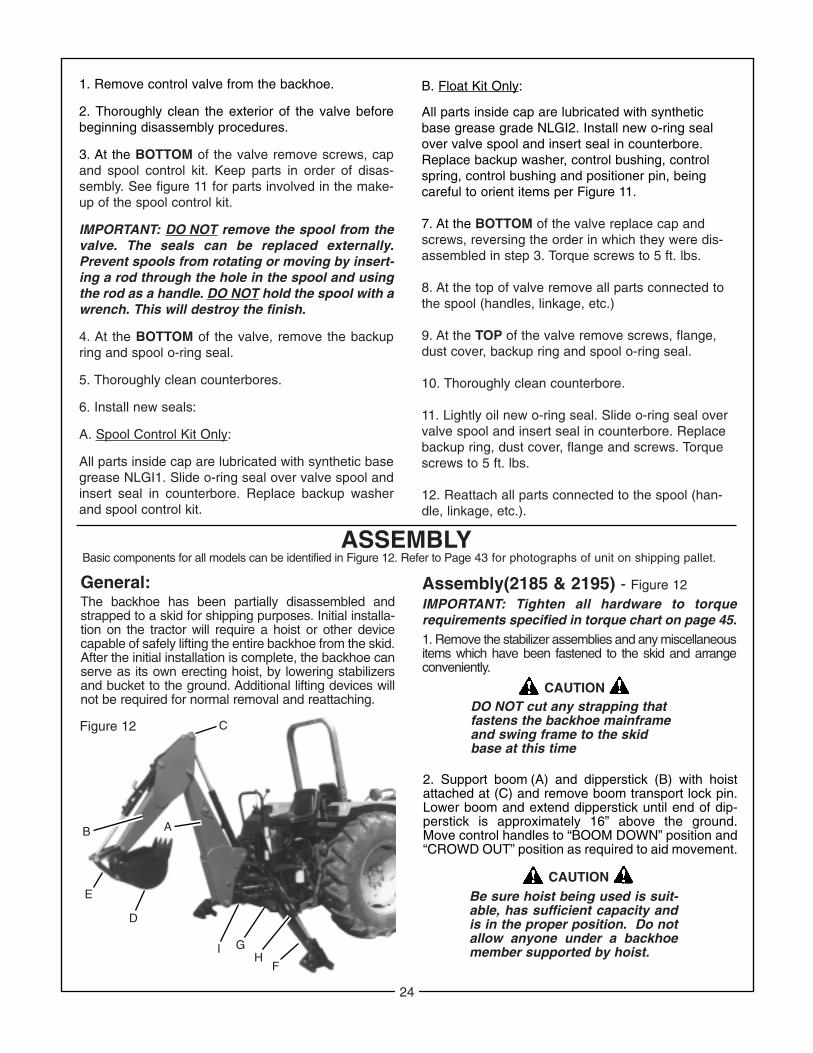
ASSEMBLYBasic components for all models can be identified in Figure 12. Refer to Page 43 for photographs of unit on shipping pallet.
General:The backhoe has been partially disassembled andstrapped to a skid for shipping purposes. Initial installa-tion on the tractor will require a hoist or other devicecapable of safely lifting the entire backhoe from the skid.After the initial installation is complete, the backhoe canserve as its own erecting hoist, by lowering stabilizersand bucket to the ground. Additional lifting devices willnot be required for normal removal and reattaching.
Assembly(2185 & 2195) - Figure 12IMPORTANT: Tighten all hardware to torquerequirements specified in torque chart on page 45.1. Remove the stabilizer assemblies and any miscellaneousitems which have been fastened to the skid and arrangeconveniently.
Be sure hoist being used is suit-able, has sufficient capacity andis in the proper position. Do notallow anyone under a backhoemember supported by hoist.
C
B
E
D
A
I GH
F
2. Support boom (A) and dipperstick (B) with hoistattached at (C) and remove boom transport lock pin.Lower boom and extend dipperstick until end of dip-perstick is approximately 16” above the ground.Move control handles to “BOOM DOWN” position and“CROWD OUT” position as required to aid movement.
1. Remove control valve from the backhoe.
2. Thoroughly clean the exterior of the valve beforebeginning disassembly procedures.
3. At the BOTTOM of the valve remove screws, capand spool control kit. Keep parts in order of disas-sembly. See figure 11 for parts involved in the make-up of the spool control kit.
IMPORTANT: DO NOT remove the spool from thevalve. The seals can be replaced externally.Prevent spools from rotating or moving by insert-ing a rod through the hole in the spool and usingthe rod as a handle. DO NOT hold the spool with awrench. This will destroy the finish.
4. At the BOTTOM of the valve, remove the backupring and spool o-ring seal.
5. Thoroughly clean counterbores.
6. Install new seals:
A. Spool Control Kit Only:
All parts inside cap are lubricated with synthetic basegrease NLGI1. Slide o-ring seal over valve spool andinsert seal in counterbore. Replace backup washerand spool control kit.
B. Float Kit Only:
All parts inside cap are lubricated with syntheticbase grease grade NLGI2. Install new o-ring sealover valve spool and insert seal in counterbore.Replace backup washer, control bushing, controlspring, control bushing and positioner pin, beingcareful to orient items per Figure 11.
7. At the BOTTOM of the valve replace cap andscrews, reversing the order in which they were dis-assembled in step 3. Torque screws to 5 ft. lbs.
8. At the top of valve remove all parts connected tothe spool (handles, linkage, etc.)
9. At the TOP of the valve remove screws, flange,dust cover, backup ring and spool o-ring seal.
10. Thoroughly clean counterbore.
11. Lightly oil new o-ring seal. Slide o-ring seal overvalve spool and insert seal in counterbore. Replacebackup ring, dust cover, flange and screws. Torquescrews to 5 ft. lbs.
12. Reattach all parts connected to the spool (han-dle, linkage, etc.).
CAUTION
DO NOT cut any strapping thatfastens the backhoe mainframeand swing frame to the skidbase at this time
CAUTION
Figure 12
3. Remove parts bag containing bucket pins frombackhoe. Attach bucket (D) to dipperstick (B) usingone pin, 3/8” bolt, and locknut.
4. Attach bucket link (E) to bucket, using same hard-ware as listed for step #3.
5. Reposition hoist on backhoe to prevent tipping andraise mainframe (G) slightly. Remove all remainingstrapping and attach stabilizers (F) to mainframe (G)using pins and hardware from parts bag.
25
6. Attach stabilizer cylinders (H) to stabilizers (F)using pins and hardware from parts bag.
7. Using caution to prevent tipping, raise mainframe(G) with hoist to a height of approximately 17” andremove skid. Block mainframe (G) and swing frame (J)securely.
8. Follow the Attaching Kit Assembly Instructions tomount the backhoe to the tractor. Check the installa-tion carefully and make sure that all members are cor-rectly installed and securely fastened.
Assembly: (2165 & 2175) - Figure 12(See “General” note, page 24)
IMPORTANT: Tighten all hardware to torquerequirements specified in torque chart on page 45.
DO NOT cut any strapping that fastens the back-hoe mainframe and swing frame to the skid atthis time.
1. Remove the stabilizer assemblies and any miscella-neous items which have been fastened to skid andarrange conveniently. Be sure hoses to stabilizer cylin-ders are routed above the cylinder-to-mainframe pivot pinconnection.
2. Support boom (A) and dipperstick (B) with hoistattached at (C) and remove boom transport lock pin.Lower boom and extend dipperstick until end of dip-perstick is approximately 16” above the ground. Movecontrol handles to “BOOM DOWN” position and“CROWD OUT” position as required to aid move-ment.
Be sure hoist being used is suitable, has suffi-cient capacity, and is in the proper position. Donot allow anyone under a backhoe member sup-ported by hoist.
3. Remove parts bag containing bucket pins frombackhoe. Attach bucket (D) to dipperstick (B) usingone pin, 3/8” bolt, and locknut.
4. Attach bucket link (E) to bucket, using same hard-ware as listed for step #3.
5. Reposition hoist on backhoe to prevent tipping andraise mainframe (G) slightly. Remove all remainingstrapping and crate base. Using caution to preventtipping, raise mainframe (G) to approximately 13” andblock mainframe and swing frame (J) securely.
6. Attach stabilizers (F) to mainframe (G) using pinsand hardware from parts bag.
7. Attach stabilizer cylinders (H) to stabilizers (F)using pins and hardware from parts bag.
8. Follow the Attaching Kit Assembly Instructions tomount the backhoe to the tractor. Check the installa-tion carefully and make sure that all members are cor-
CAUTION
CAUTION
MOUNTING KITS AND OPTIONAL KITS ASSEMBLY3- POINT HITCH LINKAGE (For 2165 & 2175)
General DescriptionMounting and hydraulic kits do not include hoses toconnect the backhoe to the tractor hydraulic system.Additional hydraulic components, hoses, and/or kitswill be required to complete the hook-up to the tractorhydraulic system. Refer to the “Hydraulic Hook-up”section for further information. PTO pump kits areavailable as options.
Mounting Backhoe to Tractor or SkidSteer loadersThe Bush Hog backhoe can be mounted to the powersource using three different attaching kits.
1. To an agricultural tractor’s 3-point hitch linkageusing the 3-point hitch kit. The 3-point hitch kit is the
same regardless of tractor model and the instructionsfor attaching the kit to the backhoe are includedbelow. See Figure 13 for general appearance.
2. To an agricultural tractor using a subframe kitspecifically offered for the tractor model and backhoebeing mounted: The subframe kit instructions differwith each tractor/backhoe combination and comeincluded with the individual subframe kit.
3. To a skid steer loader using a skid steer adaptor kitoffered for the skid steer model and backhoe seriesbeing mounted. The skid steer adapter kit instructionsdiffer with each skid steer model/backhoe combina-tion and come included with the individual skid steeradapter kit.
26
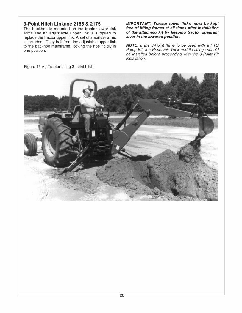
3-Point Hitch Linkage 2165 & 2175The backhoe is mounted on the tractor lower linkarms and an adjustable upper link is supplied toreplace the tractor upper link. A set of stabilizer armsis included. They bolt from the adjustable upper linkto the backhoe mainframe, locking the hoe rigidly inone position.
IMPORTANT: Tractor lower links must be keptfree of lifting forces at all times after installationof the attaching kit by keeping tractor quadrantlever in the lowered position.
NOTE: If the 3-Point Kit is to be used with a PTOPump Kit, the Reservoir Tank and its fittings shouldbe installed before proceeding with the 3-Point Kitinstallation.
Figure 13 Ag Tractor using 3-point hitch
27
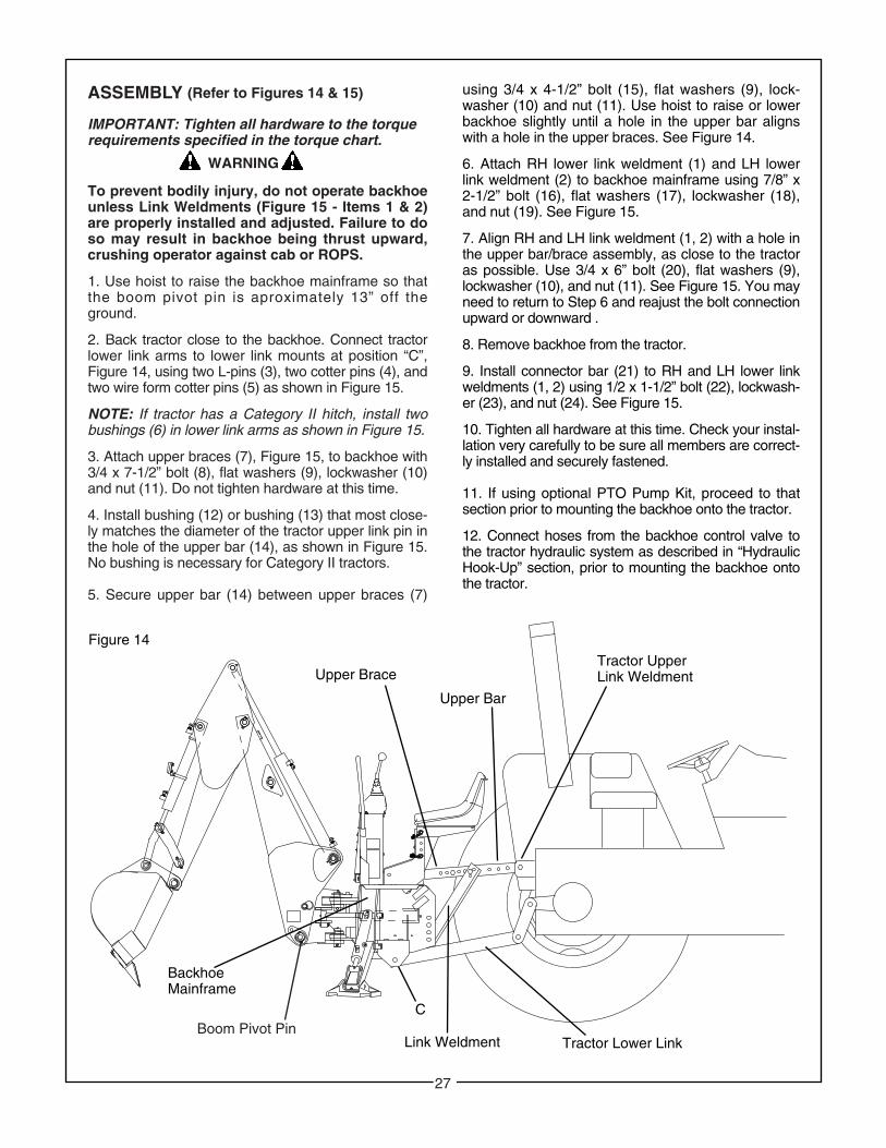
ASSEMBLY (Refer to Figures 14 & 15)
IMPORTANT: Tighten all hardware to the torquerequirements specified in the torque chart.
To prevent bodily injury, do not operate backhoeunless Link Weldments (Figure 15 - Items 1 & 2)are properly installed and adjusted. Failure to doso may result in backhoe being thrust upward,crushing operator against cab or ROPS.
1. Use hoist to raise the backhoe mainframe so thatthe boom pivot pin is aproximately 13” off theground.
2. Back tractor close to the backhoe. Connect tractorlower link arms to lower link mounts at position “C”,Figure 14, using two L-pins (3), two cotter pins (4), andtwo wire form cotter pins (5) as shown in Figure 15.
NOTE: If tractor has a Category II hitch, install twobushings (6) in lower link arms as shown in Figure 15.
3. Attach upper braces (7), Figure 15, to backhoe with3/4 x 7-1/2” bolt (8), flat washers (9), lockwasher (10)and nut (11). Do not tighten hardware at this time.
4. Install bushing (12) or bushing (13) that most close-ly matches the diameter of the tractor upper link pin inthe hole of the upper bar (14), as shown in Figure 15.No bushing is necessary for Category II tractors.
5. Secure upper bar (14) between upper braces (7)
using 3/4 x 4-1/2” bolt (15), flat washers (9), lock-washer (10) and nut (11). Use hoist to raise or lowerbackhoe slightly until a hole in the upper bar alignswith a hole in the upper braces. See Figure 14.
6. Attach RH lower link weldment (1) and LH lowerlink weldment (2) to backhoe mainframe using 7/8” x2-1/2” bolt (16), flat washers (17), lockwasher (18),and nut (19). See Figure 15.
7. Align RH and LH link weldment (1, 2) with a hole inthe upper bar/brace assembly, as close to the tractoras possible. Use 3/4 x 6” bolt (20), flat washers (9),lockwasher (10), and nut (11). See Figure 15. You mayneed to return to Step 6 and reajust the bolt connectionupward or downward .
8. Remove backhoe from the tractor.
9. Install connector bar (21) to RH and LH lower linkweldments (1, 2) using 1/2 x 1-1/2” bolt (22), lockwash-er (23), and nut (24). See Figure 15.
10. Tighten all hardware at this time. Check your instal-lation very carefully to be sure all members are correct-ly installed and securely fastened.
11. If using optional PTO Pump Kit, proceed to thatsection prior to mounting the backhoe onto the tractor.
12. Connect hoses from the backhoe control valve tothe tractor hydraulic system as described in “HydraulicHook-Up” section, prior to mounting the backhoe ontothe tractor.
Figure 14
BackhoeMainframe
Upper Brace
Link Weldment Tractor Lower Link
Upper Bar
Tractor UpperLink Weldment
C
WARNING
Boom Pivot Pin
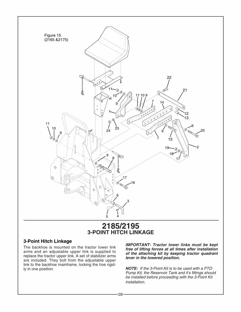
2185/21953-POINT HITCH LINKAGE
3-Point Hitch LinkageThe backhoe is mounted on the tractor lower linkarms and an adjustable upper link is supplied toreplace the tractor upper link. A set of stabilizer armsare included. They bolt from the adjustable upperlink to the backhoe mainframe, locking the hoe rigid-ly in one position.
IMPORTANT- Tractor lower links must be keptfree of lifting forces at all times after installationof the attaching kit by keeping tractor quadrantlever in the lowered position.
NOTE: If the 3-Point Kit is to be used with a PTOPump Kit, the Reservoir Tank and it’s fittings shouldbe installed before proceeding with the 3-Point Kitinstallation.
28
Figure 15(2165 &2175)
22
2111
10
9
1
2423
11 10 9
7 14
1213
920
7
9
15
219
1817
1110
9
98
1716
6
3
45
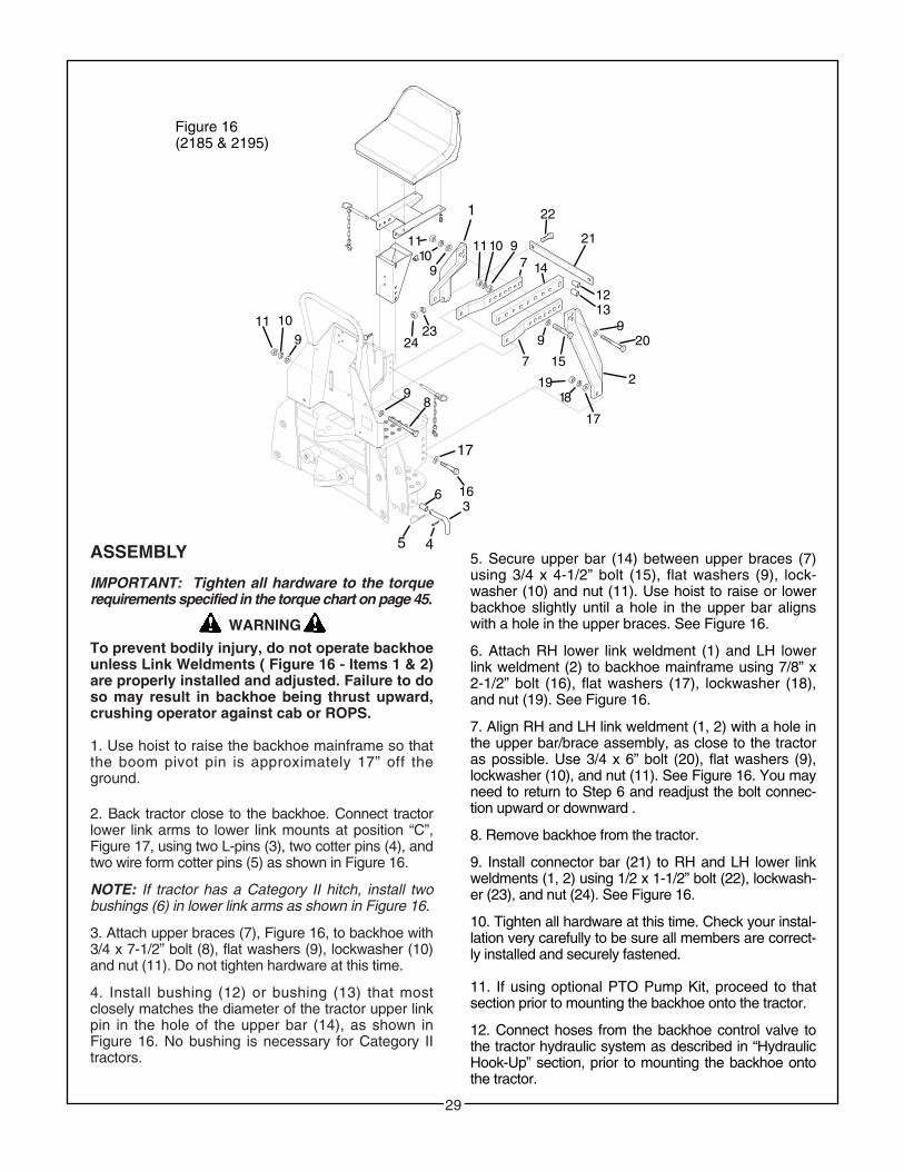
ASSEMBLY
IMPORTANT: Tighten all hardware to the torquerequirements specified in the torque chart on page 45.
To prevent bodily injury, do not operate backhoeunless Link Weldments ( Figure 16 - Items 1 & 2)are properly installed and adjusted. Failure to doso may result in backhoe being thrust upward,crushing operator against cab or ROPS.
1. Use hoist to raise the backhoe mainframe so thatthe boom pivot pin is approximately 17” off theground.
2. Back tractor close to the backhoe. Connect tractorlower link arms to lower link mounts at position “C”,Figure 17, using two L-pins (3), two cotter pins (4), andtwo wire form cotter pins (5) as shown in Figure 16.
NOTE: If tractor has a Category II hitch, install twobushings (6) in lower link arms as shown in Figure 16.
3. Attach upper braces (7), Figure 16, to backhoe with3/4 x 7-1/2” bolt (8), flat washers (9), lockwasher (10)and nut (11). Do not tighten hardware at this time.
4. Install bushing (12) or bushing (13) that mostclosely matches the diameter of the tractor upper linkpin in the hole of the upper bar (14), as shown inFigure 16. No bushing is necessary for Category IItractors.
5. Secure upper bar (14) between upper braces (7)using 3/4 x 4-1/2” bolt (15), flat washers (9), lock-washer (10) and nut (11). Use hoist to raise or lowerbackhoe slightly until a hole in the upper bar alignswith a hole in the upper braces. See Figure 16.
6. Attach RH lower link weldment (1) and LH lowerlink weldment (2) to backhoe mainframe using 7/8” x2-1/2” bolt (16), flat washers (17), lockwasher (18),and nut (19). See Figure 16.
7. Align RH and LH link weldment (1, 2) with a hole inthe upper bar/brace assembly, as close to the tractoras possible. Use 3/4 x 6” bolt (20), flat washers (9),lockwasher (10), and nut (11). See Figure 16. You mayneed to return to Step 6 and readjust the bolt connec-tion upward or downward .
8. Remove backhoe from the tractor.
9. Install connector bar (21) to RH and LH lower linkweldments (1, 2) using 1/2 x 1-1/2” bolt (22), lockwash-er (23), and nut (24). See Figure 16.
10. Tighten all hardware at this time. Check your instal-lation very carefully to be sure all members are correct-ly installed and securely fastened.
11. If using optional PTO Pump Kit, proceed to thatsection prior to mounting the backhoe onto the tractor.
12. Connect hoses from the backhoe control valve tothe tractor hydraulic system as described in “HydraulicHook-Up” section, prior to mounting the backhoe ontothe tractor.
WARNING
29
Figure 16(2185 & 2195)
119
10
98
6 163
2324
1110
9
1110 97 14
22
21
1213
920
2
9
157
1918
17
1
17
45
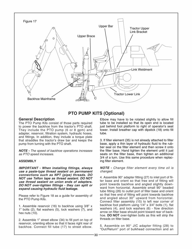
General DescriptionThe PTO Pump Kits consist of those parts requiredto power the backhoe from the tractor’s PTO shaft.They include the PTO pump (6 or 8 gpm) andadapter, reservoir, filtration system, hydraulic hoses,and fittings. In addition, they include a torque platethat straddles the tractor’s draw bar and keeps thepump from turning with the PTO shaft.
NOTE - The speed of backhoe operations increasesas PTO speed increases.
ASSEMBLY
IMPORTANT - When installing fittings, alwaysuse a paste-type thread sealant on perrmanentconnections such as NPT (pipe) threads. DONOT use Teflon tape as thread sealant. DO NOTuse thread sealant on union ends of adapters.DO NOT over-tighten fittings - they can split orexpand causing hydraulic fluid leakage.
Please refer to Figure 18 as a guide for assembly ofthe PTO Pump Kits.
1. Assemble reservoir (16) to backhoe using 3/8” x1” bolts (2), flat washers (5), lock washers (7), andhex nuts (10).
2. Assemble 1” street elbow (34) to fill port on top ofreservoir, orienting elbow so that it faces right rear ofbackhoe. Connect fill tube (17) to street elbow.
Figure 17
Backhoe Mainframe
Upper Brace
Upper BarTractor UpperLink Bracket
Link Weldment
Tractor Lower LinkC
Elbow may have to be rotated slightly to allow filltube to be installed so that its open end is locatedjust behind foot platform to right of operator’s seattower. Install breather cap with dipstick (18) onto filltube.
3. If filter element (35) is not already attached to filterbase, apply a thin layer of hydraulic fluid to the rub-ber seal on the filter element and then screw it ontothe filter base. Hand tighten the element until it justseats on the filter base, then tighten an additional3/4 of a turn. Use this same procedure when replac-ing filter element.
NOTE - Change filter element every time oil ischanged.
4. Assemble 90° adapter fitting (27) to inlet port of fil-ter base and orient so that free end of fitting willpoint towards backhoe and angled slightly down-ward from horizontal. Assemble small 90° beadedtube fitting (26) to outlet port of filter base and orientso that free end of fitting will point towards backhoeand angled about 30° upward from horizontal.Connect filter assembly (15) to left rear corner ofbackhoe foot platform using 1/4” x 3/4” bolts (1), flatwashers (4), and lock washers (6) - flow directionarrow on filter base should point toward rear of back-hoe. DO NOT over-tighten bolts as this will strip thethreads on filter base.
5. Assemble on 90° JIC adapter fitting (28) to“Out/Return” port of bulkhead connection and an
30
PTO PUMP KITS (Optional)
identical fitting to “In/Pressure” port of bulkhead con-nection. Orient fittings so that free ends of fittingspoint horizontally toward center of backhoe.
6. Take one end of 28” hydraulic hose (23) and routeunder foot platform, through hole at top of left handbackhoe side plate, and connect to 90° adapter fit-ting (27) at inlet of filter base. Connect free end ofhose to 90° JIC adapter fitting (28) on “Out/Return”port of bulkhead connection.
7. Assemble small 90° beaded tube fitting (26) to inletport at left rear of hydraulic reservoir and connect 24”return hose (21) from this fitting to 90° beaded tubefitting (26) on filter base. Secure hose to fittings ateither end using two small hose clamps (32).
8. Assemble torque plate (33) to PTO pump (12)using 1/2” x 1-1/2” bolts (3), lock washers (8), andhex nuts (11). Torque plate may need to be re-orient-ed later to accommodate different tracator configura-tions.
9. Align key slot in PTO adapter (13) with Woodruffkey on PTO pump shaft and slide PTO adapter ontopump shaft allowing 1/8” clearance between adapa-ter and pump face. Secure PTO adapter to pumpshaft with two 5/16” x 3/4” set screws (14). Place5/16” hex nuts (9) on set screws and tighten nuts toprevent set screws from loosening.
10. Assemble large 90° beaded tube fitting (24) tooutlet port at right rear of hydraulic reservoir and ori-ent free end of fitting horizontally pointing toward leftside of backhoe.
11. Assemble large 0-ring boss adapater (30) to “IN”port on PTO pump, tightening fitting until it completelybottoms-out on pump. Connect 90° beaded tube fit-ting (25) to 0-ring adapter. Beaded tube fitting mayneed to be reoriented later for proper hose routing.
12. Connect 30” suction hose (19) between 90°beaded tube fittings (24, 25) on hydraulic reservoirand PTO pump and secure hose to fittings at eitherend with large hose clamps (20).
13. Assemble small 0-ring boss adapter (31) to“OUT” port on PTO pump tightening fitting until itcompletely bottoms-out on pump. Connect 90° JICadapter (29) to 0-ring adapter. JIC adapter may needto be reoriented later for proper hose routing.
14. Connect 36” hydraulic hose (22) between 90° JICadapters (29, 28) on PTO pump and “In/Pressure”port on bulkhead connection.
IMPORTANT - If hoses are hooked-up incorrectly,serious damage to the backhoe will result.
15. NOTE: Initial filling of backhoe reservoir
requires 7 gallons of fluid. Fill reservoir with recom-mended fluid to correct level, referring to ServiceSection in Backhoe Operator’s Manual. DO NOToverfill reservoir or oil may be forced out throughbreather cap during backhoe operation.
16. Mount backhoe to tractor at this time followingprocedure in Attaching Kit Manual.
17. Slide complete PTO pump assembly onto tractorPTO shaft until PTO adapter (13) locks into grooveon PTO shaft. Make sure kinks do not develop in anyhydraulic lines. Suction hose (19) can be shortenedto help prevent kinks. Adjust orientation of 90°adapter fittings (25, 29) on PTO pump (12) asrequired to remove kinks or sharp bends in hoses.
DO NOT REMOVE TRACTOR PTO GUARD
18. Torque plate (33) may be adjusted (flipped front-to-back or bottom-to-top) on pump for proper fit-up totractor drawbar or 3-Point Hitch Kit, if necessary.Optimum position is to mount plate pointing downand over drawbar with offset in torque plate facingtowards tractor. (Refer to Figure 18)
An alternate position for torque plate is to mount itpointing upward straddling upper bar of 3-Point HitchKit. Regardless of which mounting position is usedwith torque plate, PTO pump must be restrained fromrotating.
IMPORTANT- When mounting backhoe with 3-Point Hitch Kit, do not let hydraulic lines becomeentangled in any part of Hitch Kit during installa-tion. Ensure that both pressure and suctionhoses are free from kinks or twists to reduceback pressure and to prevent excessive heatbuild-up.
19. Start tractor engine and engage tractor PTO.Cycle backhoe through all of its functions severaltimes to remove air from cylinders and hydraulic linesuntil all functions operate smoothly. After cycling allbackhoe functions, check oil level with backhoeextended to full reach and bucket rolled-back andresting on ground. If oil level on dipstick is below“ADD” line, add oil to bring oil level up to “FULL” line.DO NOT overfill reservoir or oil may be forced outthrough breather cap during backhoe operation.
HYDRAULIC HOOK-UP TO TRACTOR
If the optional PTO Pump Kit is to be used, refer tothe instructions for that kit for proper assembly.
There are four basic methods of hooking up thebackhoe to the hydraulic system of a tractor. The cor-rect method for the particular tractor will depend onthe remote couplers available, whether a loader
CAUTION
31
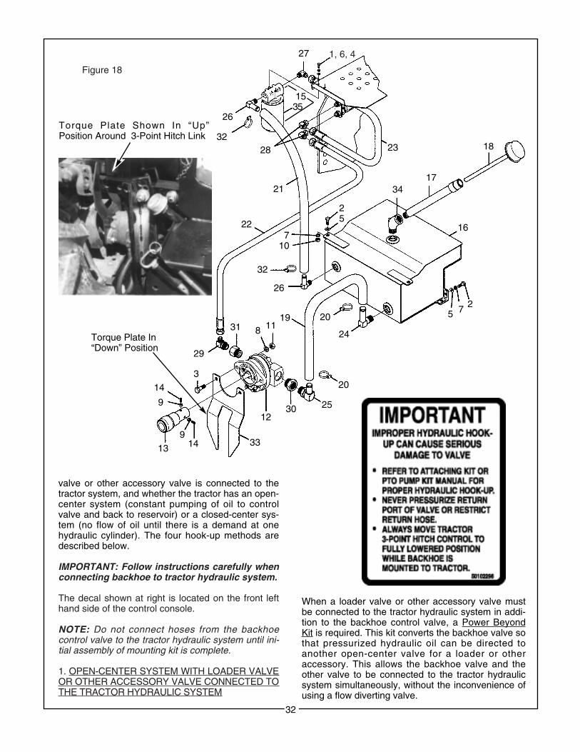
Figure 18
32
valve or other accessory valve is connected to thetractor system, and whether the tractor has an open-center system (constant pumping of oil to controlvalve and back to reservoir) or a closed-center sys-tem (no flow of oil until there is a demand at onehydraulic cylinder). The four hook-up methods aredescribed below.
IMPORTANT: Follow instructions carefully whenconnecting backhoe to tractor hydraulic system.
The decal shown at right is located on the front lefthand side of the control console.
NOTE: Do not connect hoses from the backhoecontrol valve to the tractor hydraulic system until ini-tial assembly of mounting kit is complete.
1. OPEN-CENTER SYSTEM WITH LOADER VALVEOR OTHER ACCESSORY VALVE CONNECTED TOTHE TRACTOR HYDRAULIC SYSTEM
1, 6, 427
26
32
15
28
21
22
23 18
1734
16
25
710
32
26
1931 8 11
20
253012
33
29
3
14
9
13
914
20
24
275
When a loader valve or other accessory valve mustbe connected to the tractor hydraulic system in addi-tion to the backhoe control valve, a Power BeyondKit is required. This kit converts the backhoe valve sothat pressurized hydraulic oil can be directed toanother open-center valve for a loader or otheraccessory. This allows the backhoe valve and theother valve to be connected to the tractor hydraulicsystem simultaneously, without the inconvenience ofusing a flow diverting valve.
Torque Plate Shown In “Up”Position Around 3-Point Hitch Link
Torque Plate In “Down” Position
35
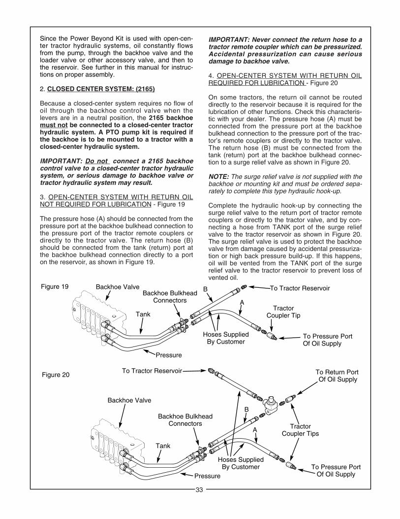
33
Since the Power Beyond Kit is used with open-cen-ter tractor hydraulic systems, oil constantly flowsfrom the pump, through the backhoe valve and theloader valve or other accessory valve, and then tothe reservoir. See further in this manual for instruc-tions on proper assembly.
2. CLOSED CENTER SYSTEM: (2165)
Because a closed-center system requires no flow ofoil through the backhoe control valve when thelevers are in a neutral position, the 2165 backhoemust not be connected to a closed-center tractorhydraulic system. A PTO pump kit is required ifthe backhoe is to be mounted to a tractor with aclosed-center hydraulic system.
IMPORTANT: Do not connect a 2165 backhoecontrol valve to a closed-center tractor hydraulicsystem, or serious damage to backhoe valve ortractor hydraulic system may result.
3. OPEN-CENTER SYSTEM WITH RETURN OILNOT REQUIRED FOR LUBRICATION - Figure 19
The pressure hose (A) should be connected from thepressure port at the backhoe bulkhead connection tothe pressure port of the tractor remote couplers ordirectly to the tractor valve. The return hose (B)should be connected from the tank (return) port atthe backhoe bulkhead connection directly to a porton the reservoir, as shown in Figure 19.
IMPORTANT: Never connect the return hose to atractor remote coupler which can be pressurized.Accidental pressurization can cause seriousdamage to backhoe valve.
4. OPEN-CENTER SYSTEM WITH RETURN OILREQUIRED FOR LUBRICATION - Figure 20
On some tractors, the return oil cannot be routeddirectly to the reservoir because it is required for thelubrication of other functions. Check this characteris-tic with your dealer. The pressure hose (A) must beconnected from the pressure port at the backhoebulkhead connection to the pressure port of the trac-tor’s remote couplers or directly to the tractor valve.The return hose (B) must be connected from thetank (return) port at the backhoe bulkhead connec-tion to a surge relief valve as shown in Figure 20.
NOTE: The surge relief valve is not supplied with thebackhoe or mounting kit and must be ordered sepa-rately to complete this type hydraulic hook-up.
Complete the hydraulic hook-up by connecting thesurge relief valve to the return port of tractor remotecouplers or directly to the tractor valve, and by con-necting a hose from TANK port of the surge reliefvalve to the tractor reservoir as shown in Figure 20.The surge relief valve is used to protect the backhoevalve from damage caused by accidental pressuriza-tion or high back pressure build-up. If this happens,oil will be vented from the TANK port of the surgerelief valve to the tractor reservoir to prevent loss ofvented oil.
Figure 19 Backhoe Valve
Tank
Pressure
Backhoe BulkheadConnectors
B
A
Hoses SuppliedBy Customer
To Tractor Reservoir
TractorCoupler Tip
Figure 20
Backhoe Valve
Tank
Pressure
Backhoe Bulkhead Connectors
Hoses SuppliedBy Customer
B
A
To Tractor Reservoir
TractorCoupler Tips
To Return PortOf Oil Supply
To Pressure PortOf Oil Supply
To Pressure PortOf Oil Supply
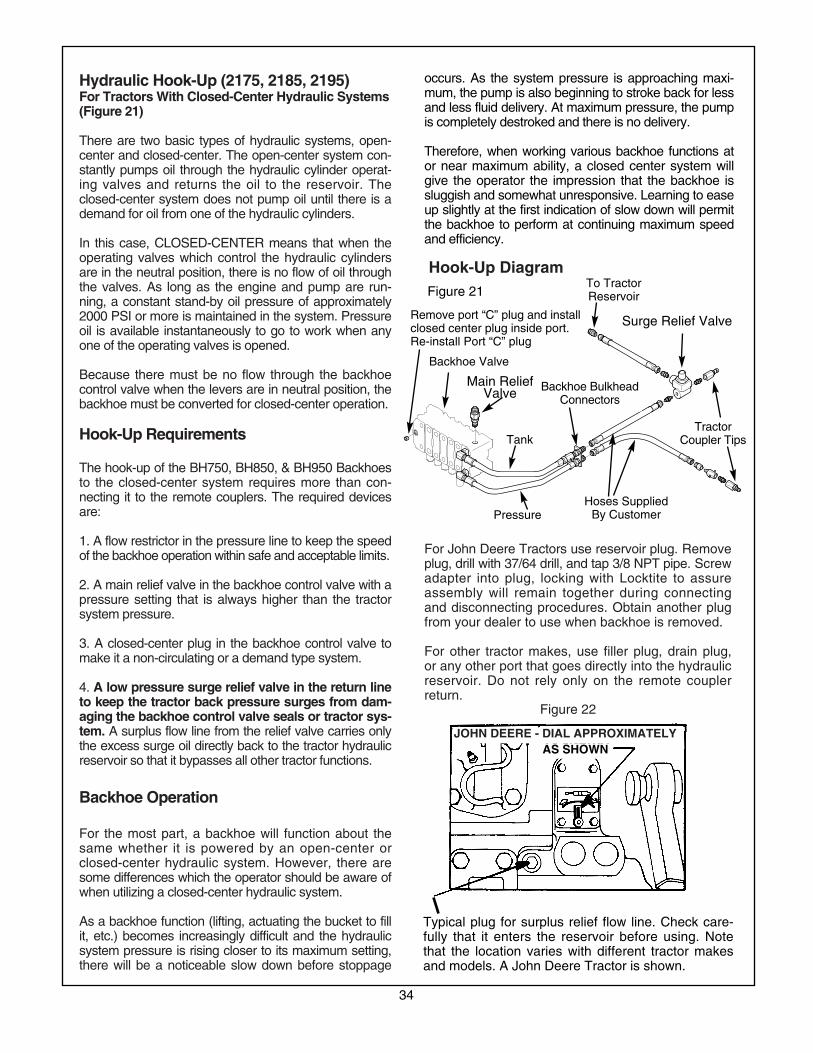
Hydraulic Hook-Up (2175, 2185, 2195)For Tractors With Closed-Center Hydraulic Systems(Figure 21)
There are two basic types of hydraulic systems, open-center and closed-center. The open-center system con-stantly pumps oil through the hydraulic cylinder operat-ing valves and returns the oil to the reservoir. Theclosed-center system does not pump oil until there is ademand for oil from one of the hydraulic cylinders.
In this case, CLOSED-CENTER means that when theoperating valves which control the hydraulic cylindersare in the neutral position, there is no flow of oil throughthe valves. As long as the engine and pump are run-ning, a constant stand-by oil pressure of approximately2000 PSI or more is maintained in the system. Pressureoil is available instantaneously to go to work when anyone of the operating valves is opened.
Because there must be no flow through the backhoecontrol valve when the levers are in neutral position, thebackhoe must be converted for closed-center operation.
Hook-Up Requirements
The hook-up of the BH750, BH850, & BH950 Backhoesto the closed-center system requires more than con-necting it to the remote couplers. The required devicesare:
1. A flow restrictor in the pressure line to keep the speedof the backhoe operation within safe and acceptable limits.
2. A main relief valve in the backhoe control valve with apressure setting that is always higher than the tractorsystem pressure.
3. A closed-center plug in the backhoe control valve tomake it a non-circulating or a demand type system.
4. A low pressure surge relief valve in the return lineto keep the tractor back pressure surges from dam-aging the backhoe control valve seals or tractor sys-tem. A surplus flow line from the relief valve carries onlythe excess surge oil directly back to the tractor hydraulicreservoir so that it bypasses all other tractor functions.
Backhoe Operation
For the most part, a backhoe will function about thesame whether it is powered by an open-center orclosed-center hydraulic system. However, there aresome differences which the operator should be aware ofwhen utilizing a closed-center hydraulic system.
As a backhoe function (lifting, actuating the bucket to fillit, etc.) becomes increasingly difficult and the hydraulicsystem pressure is rising closer to its maximum setting,there will be a noticeable slow down before stoppage
occurs. As the system pressure is approaching maxi-mum, the pump is also beginning to stroke back for lessand less fluid delivery. At maximum pressure, the pumpis completely destroked and there is no delivery.
Therefore, when working various backhoe functions ator near maximum ability, a closed center system willgive the operator the impression that the backhoe issluggish and somewhat unresponsive. Learning to easeup slightly at the first indication of slow down will permitthe backhoe to perform at continuing maximum speedand efficiency.
Hook-Up Diagram
For John Deere Tractors use reservoir plug. Removeplug, drill with 37/64 drill, and tap 3/8 NPT pipe. Screwadapter into plug, locking with Locktite to assureassembly will remain together during connectingand disconnecting procedures. Obtain another plugfrom your dealer to use when backhoe is removed.
For other tractor makes, use filler plug, drain plug,or any other port that goes directly into the hydraulicreservoir. Do not rely only on the remote couplerreturn.
Typical plug for surplus relief flow line. Check care-fully that it enters the reservoir before using. Notethat the location varies with different tractor makesand models. A John Deere Tractor is shown.
JOHN DEERE - DIAL APPROXIMATELYAS SHOWN
Figure 22
34
Figure 21
Remove port “C” plug and installclosed center plug inside port.Re-install Port “C” plug
Backhoe Valve
Tank
Pressure
To TractorReservoir
Backhoe BulkheadConnectors
Hoses SuppliedBy Customer
TractorCoupler Tips
Surge Relief Valve
Main Relief Valve
35
POWER BEYOND KITSFOR TRACTORS WITH OPEN-CENTER HYDRAULIC SYSTEMS
General DescriptionA power beyond application is required to convert ahydraulic valve so that pressurized oil can be directedto another “open center” valve. This allows the back-hoe valve and a loader valve, or other accessory, tobe connected to the tractor hydraulic system simulta-neously, without the inconvenience of using a flowdiverting valve.
Since the power beyond application is only requiredon “open center” hydraulic systems, oil will be con-stantly flowing from the pump through the backhoeand loader or other accessory valve, and then back tothe reservoir. “Open center” refers to this constantflow through the open center of the valves.
The assembly instructions cover two conditions thatrequire a power beyond kit to be ordered from GreatBend. The first procedure shows the recommendedmethod of connecting a Great Bend loader with aGreat Bend valve to a Great Bend backhoe. The sec-ond procedure shows the recommended method forconnecting a Great Bend backhoe and a competitiveloader or a non Great Bend valve. The second is alsoused to operate the backhoe and loader off the back-hoe PTO pump kit option. In the first procedure, thepower beyond plug is included with the loader valvewhen the valve is ordered. The second procedurerequires the power beyond kit for the backhoe valvebe ordered from Great Bend as a separate item.
The hoses and fittings required in either procedure toconnect the two valves together are not supplied. Theproper fittings and hose lengths required must bedetermined for each specific application. The partsmust be supplied by the customer.
Tractor Preparation
Stop tractor, lower all attachments to the ground, andrelieve pressure in all hydraulic lines by moving allcontrol handles back and forth or side to side severaltimes.
Note: The terms RIGHT and LEFT for all adapterparts are determined from the position of the operatorwhen seated in the operating position on the backhoe.
FIRST PROCEDUREASSEMBLY OF A BUSH HOG BACKHOETO A GREAT BEND LOADER VALVE
IMPORTANT: Improper hydraulic hook-up cancause serious damage to backhoe control valve orother hydraulic components. Refer to the GreatBend loader Operator’s Manual during this proce-dure.
When connecting the Great Bend backhoe valve to aGreat Bend front end loader valve, the input pressureline from the tractor will be connected to the loadervalve first. The power beyond pressure line will beconnected to the input pressure port of the backhoevalve. In order to properly plumb the system, theloader valve will require converting to a power beyondvalve. Refer to the Operator’s Manual received withthe loader for the proper assembly of the powerbeyond valve.
There have been several different valves used on theGreat Bend loader in past years. The fittings requiredto convert the Great Bend loader valve to a powerbeyond application are included in the loader valvekit. If the fittings (or plugs) cannot be located, they canbe obtained from Great Bend Service Parts. Beforeattempting to order the plug you must first determinethe manufacturer of the loader valve assembled toyour loader. This can be determined from the identifi-cation plate located on the valve.
1. Install the power beyond plug received with theloader valve into valve cavity as shown in Figure 23(Page 36). Make sure O-rings on sleeve are posi-tioned properly and are not pinched or damaged.
2. Install a pressure line (supplied by customer)between the tractor pressure “out” port and the pres-sure inlet port of the loader valve.
3. Install a pressure line (supplied by customer) betweenthe power beyond fitting of the loader valve and the pres-sure inlet port on the backhoe bulkhead connection asshown in Figure 23.
4. Complete assembly of “return” hoses as shown inFigure 23. Connect tee fitting to return outlet port on thebackhoe bulkhead connector as shown. Connect returnhose from rerturn outlet port of the loader valve to thebranch port of the tee fitting. Hoses and tee supplied bycustomer. Connect a second return hose from the tee fit-ting directly to a port on the tractor reservoir as shown inFigure 23.
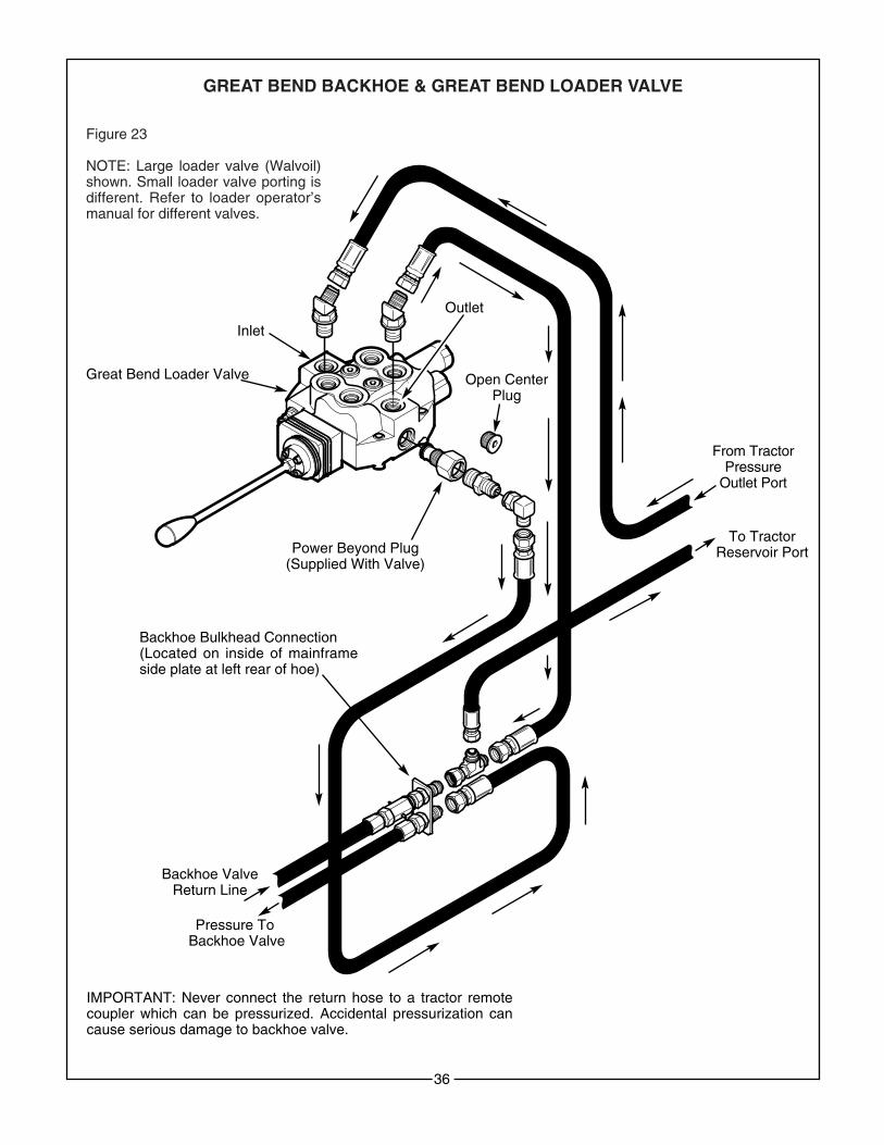
GREAT BEND BACKHOE & GREAT BEND LOADER VALVE
Figure 23
NOTE: Large loader valve (Walvoil)shown. Small loader valve porting isdifferent. Refer to loader operator’smanual for different valves.
Backhoe Bulkhead Connection(Located on inside of mainframeside plate at left rear of hoe)
Inlet
Great Bend Loader Valve
Outlet
Open CenterPlug
Power Beyond Plug(Supplied With Valve)
From TractorPressure
Outlet Port
IMPORTANT: Never connect the return hose to a tractor remotecoupler which can be pressurized. Accidental pressurization cancause serious damage to backhoe valve.
Backhoe ValveReturn Line
Pressure ToBackhoe Valve
To TractorReservoir Port
36
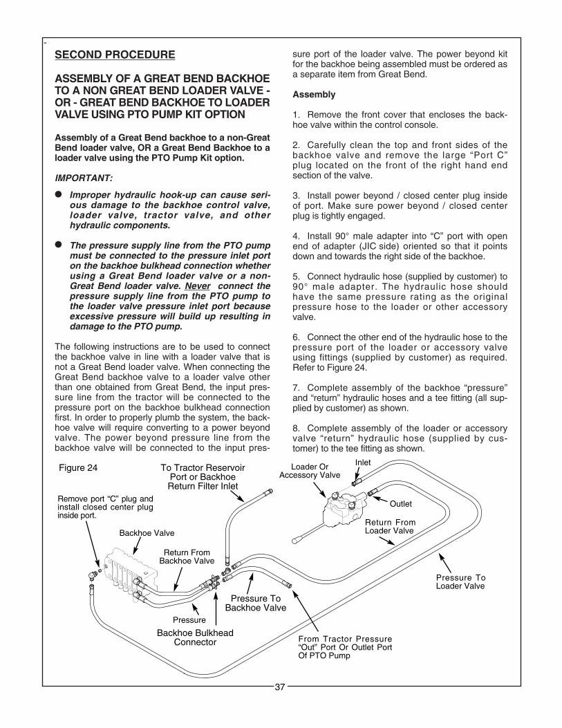
-SECOND PROCEDURE
ASSEMBLY OF A GREAT BEND BACKHOETO A NON GREAT BEND LOADER VALVE -OR - GREAT BEND BACKHOE TO LOADERVALVE USING PTO PUMP KIT OPTION
Assembly of a Great Bend backhoe to a non-GreatBend loader valve, OR a Great Bend Backhoe to aloader valve using the PTO Pump Kit option.
IMPORTANT:
Improper hydraulic hook-up can cause seri-ous damage to the backhoe control valve,loader valve, tractor valve, and other hydraulic components.
The pressure supply line from the PTO pump must be connected to the pressure inlet port on the backhoe bulkhead connection whether using a Great Bend loader valve or a non-Great Bend loader valve. Never connect the pressure supply line from the PTO pump to the loader valve pressure inlet port because excessive pressure will build up resulting in damage to the PTO pump.
The following instructions are to be used to connectthe backhoe valve in line with a loader valve that isnot a Great Bend loader valve. When connecting theGreat Bend backhoe valve to a loader valve otherthan one obtained from Great Bend, the input pres-sure line from the tractor will be connected to thepressure port on the backhoe bulkhead connectionfirst. In order to properly plumb the system, the back-hoe valve will require converting to a power beyondvalve. The power beyond pressure line from thebackhoe valve will be connected to the input pres-
●
●
sure port of the loader valve. The power beyond kitfor the backhoe being assembled must be ordered asa separate item from Great Bend.
Assembly
1. Remove the front cover that encloses the back-hoe valve within the control console.
2. Carefully clean the top and front sides of thebackhoe valve and remove the large “Port C”plug located on the front of the right hand end section of the valve.
3. Install power beyond / closed center plug inside of port. Make sure power beyond / closed centerplug is tightly engaged.
4. Install 90° male adapter into “C” port with openend of adapter (JIC side) oriented so that it points down and towards the right side of the backhoe.
5. Connect hydraulic hose (supplied by customer) to 90° male adapter. The hydraulic hose should have the same pressure rating as the originalpressure hose to the loader or other accessoryvalve.
6. Connect the other end of the hydraulic hose to the pressure port of the loader or accessory valve using fittings (supplied by customer) as required. Refer to Figure 24.
7. Complete assembly of the backhoe “pressure” and “return” hydraulic hoses and a tee fitting (all sup-plied by customer) as shown.
8. Complete assembly of the loader or accessory valve “return” hydraulic hose (supplied by cus-tomer) to the tee fitting as shown.
37
Figure 24
Remove port “C” plug andinstall closed center pluginside port.
Backhoe Valve
Return FromBackhoe Valve
Backhoe BulkheadConnector
To Tractor ReservoirPort or BackhoeReturn Filter Inlet
Pressure ToBackhoe Valve
From Tractor Pressure“Out” Port Or Outlet PortOf PTO Pump
Loader OrAccessory Valve
Outlet
Inlet
Return FromLoader Valve
Pressure ToLoader Valve
Pressure
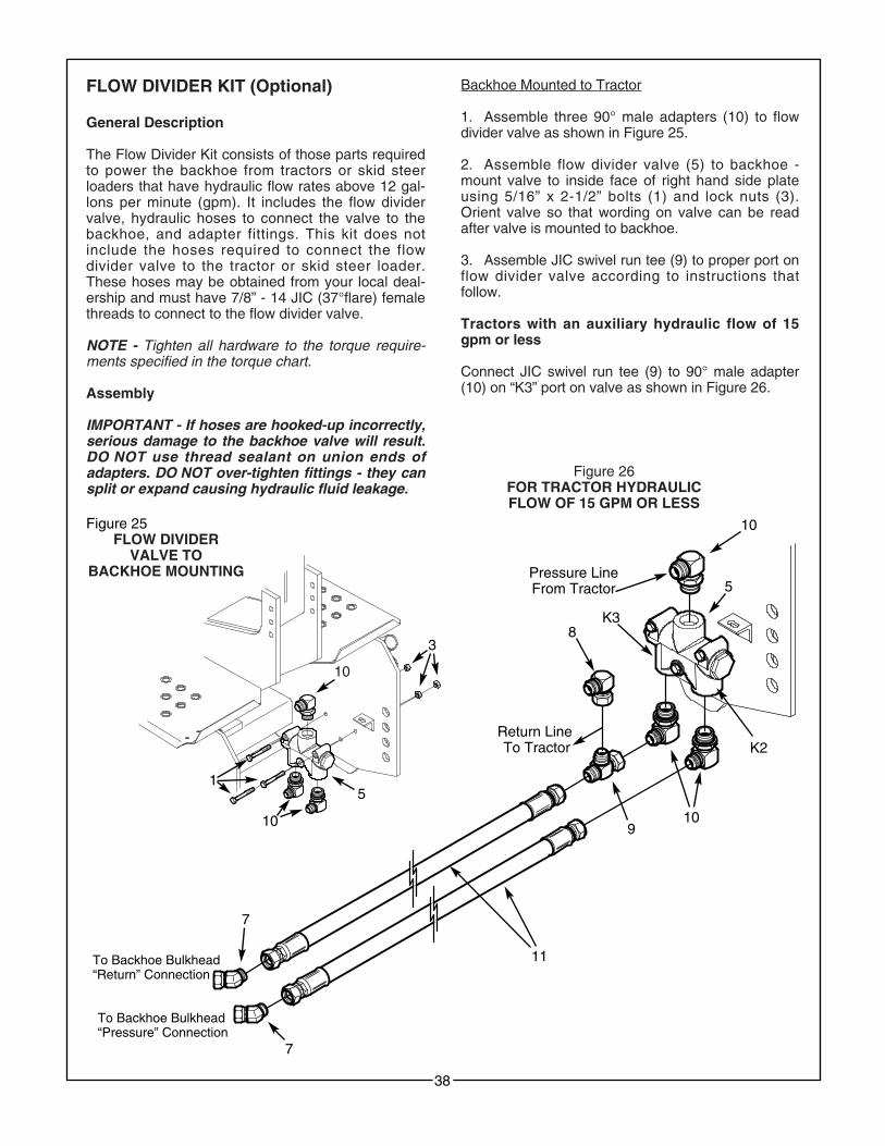
FLOW DIVIDER KIT (Optional)
General Description
The Flow Divider Kit consists of those parts requiredto power the backhoe from tractors or skid steerloaders that have hydraulic flow rates above 12 gal-lons per minute (gpm). It includes the flow dividervalve, hydraulic hoses to connect the valve to thebackhoe, and adapter fittings. This kit does notinclude the hoses required to connect the flowdivider valve to the tractor or skid steer loader.These hoses may be obtained from your local deal-ership and must have 7/8” - 14 JIC (37°flare) femalethreads to connect to the flow divider valve.
NOTE - Tighten all hardware to the torque require-ments specified in the torque chart.
Assembly
IMPORTANT - If hoses are hooked-up incorrectly,serious damage to the backhoe valve will result.DO NOT use thread sealant on union ends ofadapters. DO NOT over-tighten fittings - they cansplit or expand causing hydraulic fluid leakage.
Backhoe Mounted to Tractor
1. Assemble three 90° male adapters (10) to flowdivider valve as shown in Figure 25.
2. Assemble flow divider valve (5) to backhoe -mount valve to inside face of right hand side plateusing 5/16” x 2-1/2” bolts (1) and lock nuts (3).Orient valve so that wording on valve can be read after valve is mounted to backhoe.
3. Assemble JIC swivel run tee (9) to proper port onflow divider valve according to instructions thatfollow.
Tractors with an auxiliary hydraulic flow of 15gpm or less
Connect JIC swivel run tee (9) to 90° male adapter(10) on “K3” port on valve as shown in Figure 26.
Figure 25 FLOW DIVIDER
VALVE TOBACKHOE MOUNTING
Figure 26FOR TRACTOR HYDRAULICFLOW OF 15 GPM OR LESS
10
5
10
3
Pressure LineFrom Tractor
Return LineTo Tractor
To Backhoe Bulkhead“Return” Connection
To Backhoe Bulkhead“Pressure” Connection
7
7
11
8
910
10
5
K2
K3
38
1
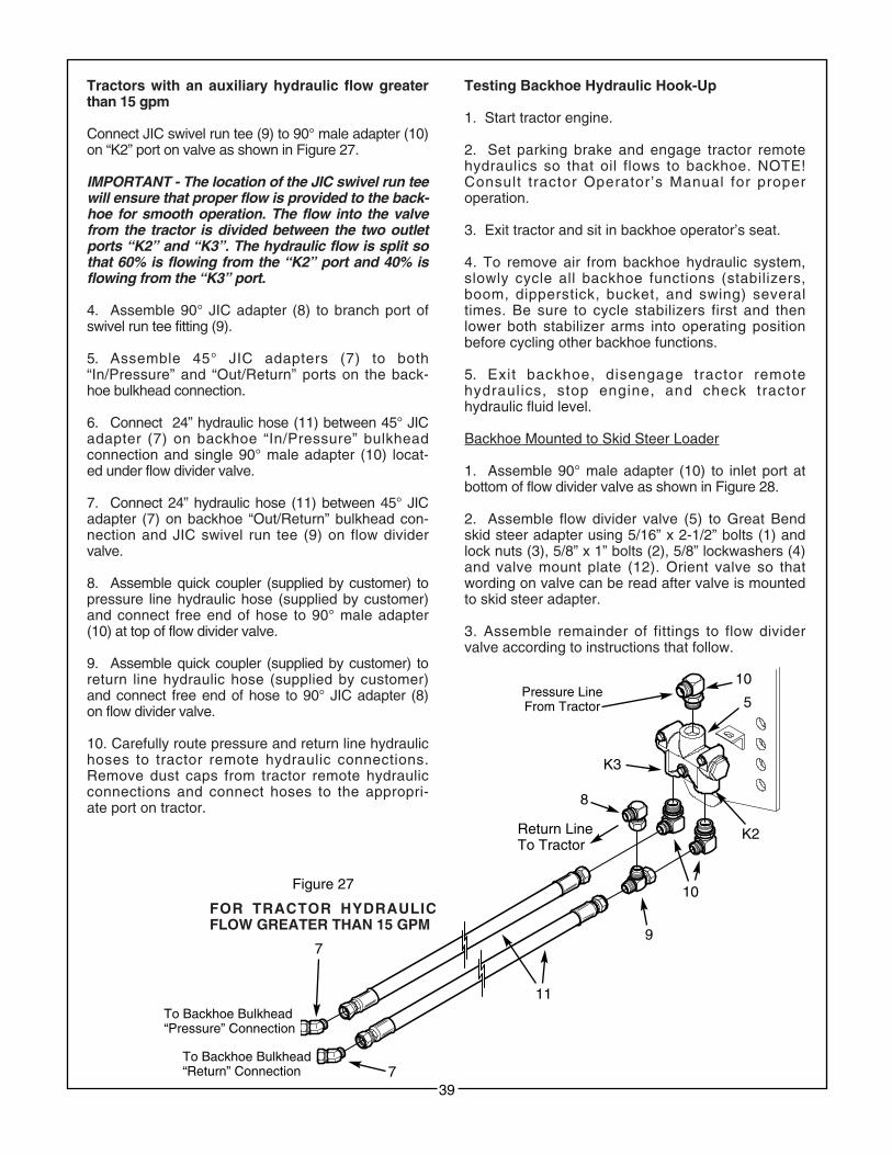
Tractors with an auxiliary hydraulic flow greaterthan 15 gpm
Connect JIC swivel run tee (9) to 90° male adapter (10)on “K2” port on valve as shown in Figure 27.
IMPORTANT - The location of the JIC swivel run teewill ensure that proper flow is provided to the back-hoe for smooth operation. The flow into the valvefrom the tractor is divided between the two outletports “K2” and “K3”. The hydraulic flow is split sothat 60% is flowing from the “K2” port and 40% isflowing from the “K3” port.
4. Assemble 90° JIC adapter (8) to branch port of swivel run tee fitting (9).
5. Assemble 45° JIC adapters (7) to both“In/Pressure” and “Out/Return” ports on the back-hoe bulkhead connection.
6. Connect 24” hydraulic hose (11) between 45° JICadapter (7) on backhoe “In/Pressure” bulkhead connection and single 90° male adapter (10) locat-ed under flow divider valve.
7. Connect 24” hydraulic hose (11) between 45° JIC adapter (7) on backhoe “Out/Return” bulkhead con-nection and JIC swivel run tee (9) on flow divider valve.
8. Assemble quick coupler (supplied by customer) to pressure line hydraulic hose (supplied by customer) and connect free end of hose to 90° male adapter (10) at top of flow divider valve.
9. Assemble quick coupler (supplied by customer) toreturn line hydraulic hose (supplied by customer) and connect free end of hose to 90° JIC adapter (8) on flow divider valve.
10. Carefully route pressure and return line hydraulic hoses to tractor remote hydraulic connections.Remove dust caps from tractor remote hydraulicconnections and connect hoses to the appropri-ate port on tractor.
Testing Backhoe Hydraulic Hook-Up
1. Start tractor engine.
2. Set parking brake and engage tractor remotehydraulics so that oil flows to backhoe. NOTE!Consult tractor Operator ’s Manual for properoperation.
3. Exit tractor and sit in backhoe operator’s seat.
4. To remove air from backhoe hydraulic system, slowly cycle all backhoe functions (stabilizers, boom, dipperstick, bucket, and swing) several times. Be sure to cycle stabilizers first and thenlower both stabilizer arms into operating position before cycling other backhoe functions.
5. Exit backhoe, disengage tractor remotehydraulics, stop engine, and check tractorhydraulic fluid level.
Backhoe Mounted to Skid Steer Loader
1. Assemble 90° male adapter (10) to inlet port at bottom of flow divider valve as shown in Figure 28.
2. Assemble flow divider valve (5) to Great Bendskid steer adapter using 5/16” x 2-1/2” bolts (1) and lock nuts (3), 5/8” x 1” bolts (2), 5/8” lockwashers (4)and valve mount plate (12). Orient valve so thatwording on valve can be read after valve is mountedto skid steer adapter.
3. Assemble remainder of fittings to flow dividervalve according to instructions that follow.
39
To Backhoe Bulkhead“Pressure” Connection
To Backhoe Bulkhead“Return” Connection
10
5
K2
K3
Pressure LineFrom Tractor
8
10
9
11
7
7
Figure 27
Return LineTo Tractor
FOR TRACTOR HYDRAULICFLOW GREATER THAN 15 GPM
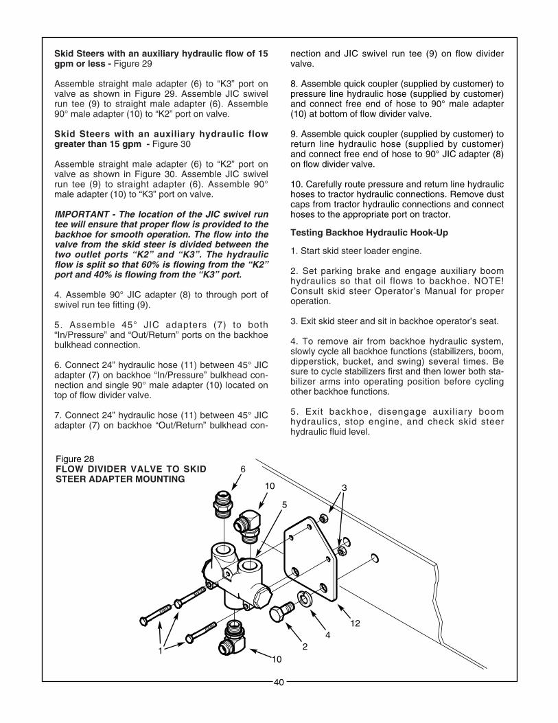
Skid Steers with an auxiliary hydraulic flow of 15gpm or less - Figure 29
Assemble straight male adapter (6) to “K3” port onvalve as shown in Figure 29. Assemble JIC swivelrun tee (9) to straight male adapter (6). Assemble90° male adapter (10) to “K2” port on valve.
Skid Steers with an auxiliary hydraulic flowgreater than 15 gpm - Figure 30
Assemble straight male adapter (6) to “K2” port onvalve as shown in Figure 30. Assemble JIC swivelrun tee (9) to straight adapter (6). Assemble 90°male adapter (10) to “K3” port on valve.
IMPORTANT - The location of the JIC swivel runtee will ensure that proper flow is provided to thebackhoe for smooth operation. The flow into thevalve from the skid steer is divided between thetwo outlet ports “K2” and “K3”. The hydraulicflow is split so that 60% is flowing from the “K2”port and 40% is flowing from the “K3” port.
4. Assemble 90° JIC adapter (8) to through port ofswivel run tee fitting (9).
5. Assemble 45° JIC adapters (7) to both“In/Pressure” and “Out/Return” ports on the backhoebulkhead connection.
6. Connect 24” hydraulic hose (11) between 45° JICadapter (7) on backhoe “In/Pressure” bulkhead con-nection and single 90° male adapter (10) located ontop of flow divider valve.
7. Connect 24” hydraulic hose (11) between 45° JICadapter (7) on backhoe “Out/Return” bulkhead con-
nection and JIC swivel run tee (9) on flow dividervalve.
8. Assemble quick coupler (supplied by customer) topressure line hydraulic hose (supplied by customer)and connect free end of hose to 90° male adapter(10) at bottom of flow divider valve.
9. Assemble quick coupler (supplied by customer) toreturn line hydraulic hose (supplied by customer)and connect free end of hose to 90° JIC adapter (8)on flow divider valve.
10. Carefully route pressure and return line hydraulichoses to tractor hydraulic connections. Remove dustcaps from tractor hydraulic connections and connecthoses to the appropriate port on tractor.
Testing Backhoe Hydraulic Hook-Up
1. Start skid steer loader engine.
2. Set parking brake and engage auxiliary boomhydraulics so that oil flows to backhoe. NOTE!Consult skid steer Operator’s Manual for properoperation.
3. Exit skid steer and sit in backhoe operator’s seat.
4. To remove air from backhoe hydraulic system,slowly cycle all backhoe functions (stabilizers, boom,dipperstick, bucket, and swing) several times. Besure to cycle stabilizers first and then lower both sta-bilizer arms into operating position before cyclingother backhoe functions.
5. Exit backhoe, disengage auxil iary boomhydraulics, stop engine, and check skid steerhydraulic fluid level.
40
Figure 28FLOW DIVIDER VALVE TO SKIDSTEER ADAPTER MOUNTING
6
10
5
3
124
210
1
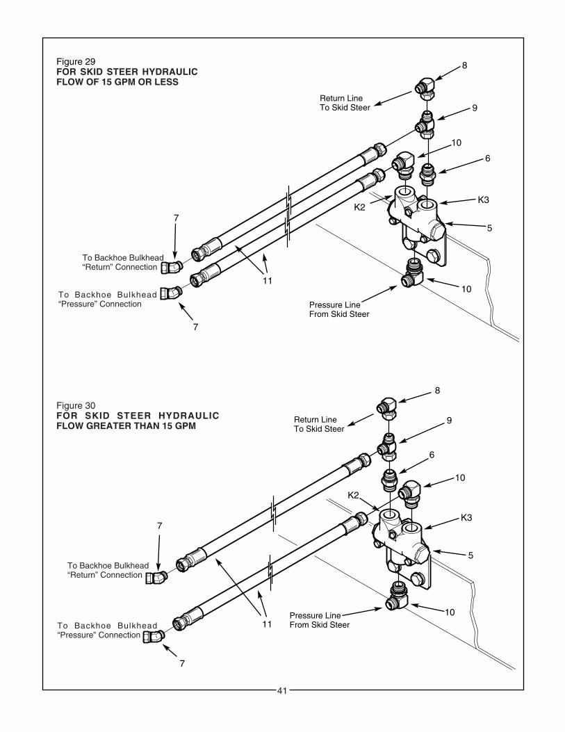
41
Figure 29FOR SKID STEER HYDRAULICFLOW OF 15 GPM OR LESS
Figure 30FOR SKID STEER HYDRAULICFLOW GREATER THAN 15 GPM
To Backhoe Bulkhead“Return” Connection
To Backhoe Bulkhead“Return” Connection
To Backhoe Bulkhead“Pressure” Connection
To Backhoe Bulkhead“Pressure” Connection
Return LineTo Skid Steer
Return LineTo Skid Steer
7
7
7
7
11
11
Pressure Line From Skid Steer
Pressure Line From Skid Steer
8
9
6
K3K2
5
10
8
9
6
10
K3
K2
5
10
10
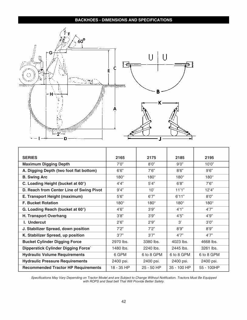
BACKHOES - DIMENSIONS AND SPECIFICATIONS
42
Specifications May Vary Depending on Tractor Model and are Subject to Change Without Notification. Tractors Must Be Equippedwith ROPS and Seat belt That Will Provide Better Safety.
SERIES 2165 2175 2185 2195
Maximum Digging Depth 7’0” 8’0” 9’0” 10’0”
A. Digging Depth (two foot flat bottom) 6’6” 7’6” 8’6” 9’6”
B. Swing Arc 180° 180° 180° 180°
C. Loading Height (bucket at 60°) 4’4” 5’4” 6’8” 7’6”
D. Reach from Center Line of Swing Pivot 9’4” 10’ 11’1” 12’4”
E. Transport Height (maximum) 5’6” 6’7” 6’11” 8’0”
F. Bucket Rotation 180° 180° 180° 180°
G. Loading Reach (bucket at 60°) 4’6” 3’9” 4’1” 4’7”
H. Transport Overhang 3’8” 3’9” 4’5” 4’9”
I. Undercut 2’6” 2’9” 3’ 3’0”
J. Stabilizer Spread, down position 7’2” 7’2” 8’9” 8’9”
K. Stabilizer Spread, up position 3’7” 3’7” 4’7” 4’7”
Bucket Cylinder Digging Force 2970 lbs. 3380 lbs. 4023 lbs. 4668 lbs.
Dipperstick Cylinder Digging Force` 1480 lbs. 2240 lbs. 2445 lbs. 3261 lbs.
Hydraulic Volume Requirements 6 GPM 6 to 8 GPM 6 to 8 GPM 6 to 8 GPM
Hydraulic Pressure Requirements 2400 psi. 2400 psi. 2400 psi. 2400 psi.
Recommended Tractor HP Requirements 18 - 35 HP 25 - 50 HP 35 - 100 HP 55 - 100HP
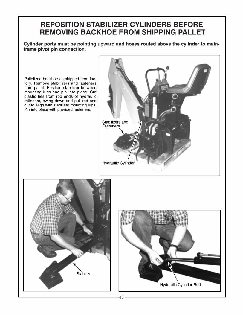
REPOSITION STABILIZER CYLINDERS BEFOREREMOVING BACKHOE FROM SHIPPING PALLET
Cylinder ports must be pointing upward and hoses routed above the cylinder to main-frame pivot pin connection.
43
Palletized backhoe as shipped from fac-tory. Remove stabilizers and fastenersfrom pallet. Position stabilizer betweenmounting lugs and pin into place. Cutplastic ties from rod ends of hydrauliccylinders, swing down and pull rod endout to align with stabilizer mounting lugs.Pin into place with provided fasteners.
Stabilizers and Fasteners
Hydraulic Cylinder
Stabilizer
Hydraulic Cylinder Rod

SAFETY DECALSThe safety of the operator was a prime consideration in the design of the backhoe. Proper shielding, conve-
nient controls, simple adjustments and other safety features have been built into this implement. The followingdecals are located on the backhoe. Keep decals clean and replace them immediately if they are missing.
Contact your dealer or Great Bend for replacements.
44
5010229350100238
5010229250102292
50033364
50102294 50033476 50102523 50033477
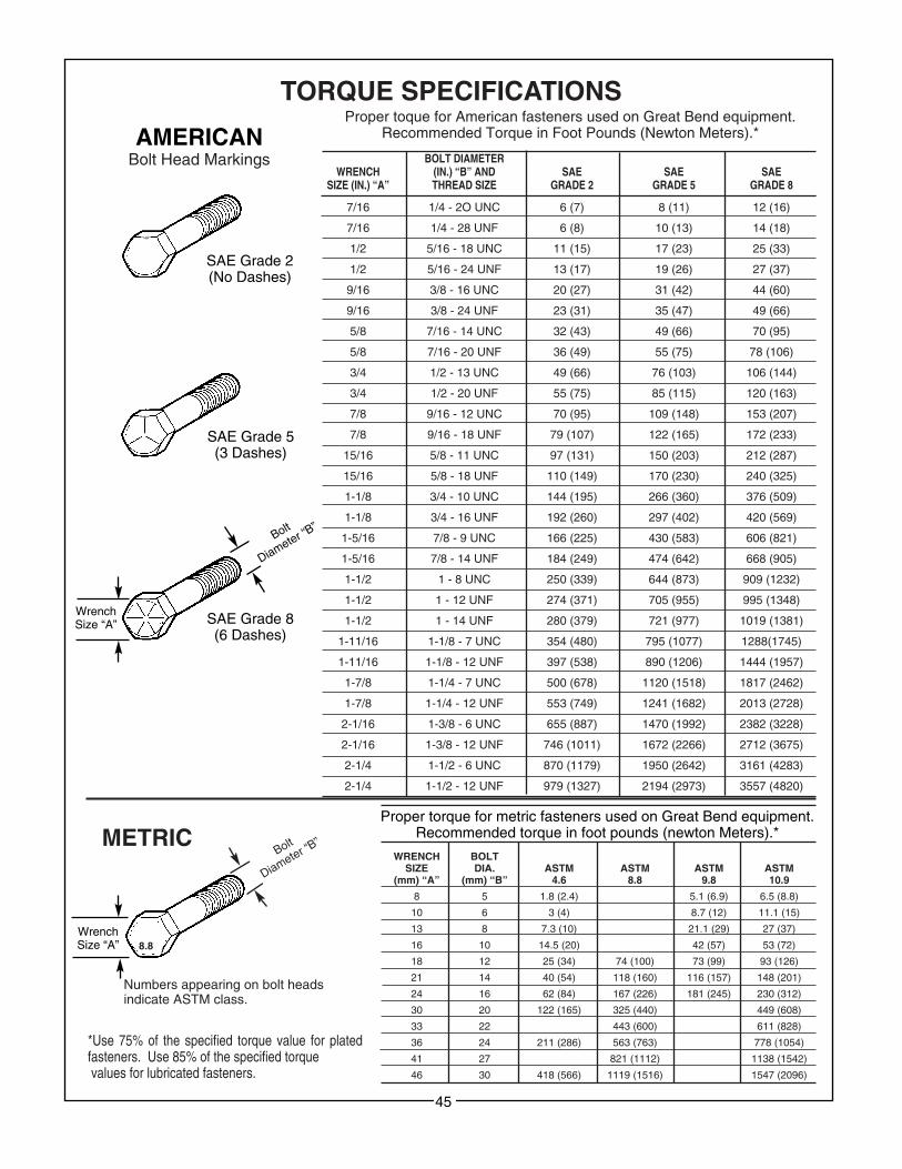
TORQUE SPECIFICATIONSProper toque for American fasteners used on Great Bend equipment.
Recommended Torque in Foot Pounds (Newton Meters).*
BOLT DIAMETERWRENCH (IN.) “B” AND SAE SAE SAE
SIZE (IN.) “A” THREAD SIZE GRADE 2 GRADE 5 GRADE 8
7/16 1/4 - 2O UNC 6 (7) 8 (11) 12 (16)
7/16 1/4 - 28 UNF 6 (8) 10 (13) 14 (18)
1/2 5/16 - 18 UNC 11 (15) 17 (23) 25 (33)
1/2 5/16 - 24 UNF 13 (17) 19 (26) 27 (37)
9/16 3/8 - 16 UNC 20 (27) 31 (42) 44 (60)
9/16 3/8 - 24 UNF 23 (31) 35 (47) 49 (66)
5/8 7/16 - 14 UNC 32 (43) 49 (66) 70 (95)
5/8 7/16 - 20 UNF 36 (49) 55 (75) 78 (106)
3/4 1/2 - 13 UNC 49 (66) 76 (103) 106 (144)
3/4 1/2 - 20 UNF 55 (75) 85 (115) 120 (163)
7/8 9/16 - 12 UNC 70 (95) 109 (148) 153 (207)
7/8 9/16 - 18 UNF 79 (107) 122 (165) 172 (233)
15/16 5/8 - 11 UNC 97 (131) 150 (203) 212 (287)
15/16 5/8 - 18 UNF 110 (149) 170 (230) 240 (325)
1-1/8 3/4 - 10 UNC 144 (195) 266 (360) 376 (509)
1-1/8 3/4 - 16 UNF 192 (260) 297 (402) 420 (569)
1-5/16 7/8 - 9 UNC 166 (225) 430 (583) 606 (821)
1-5/16 7/8 - 14 UNF 184 (249) 474 (642) 668 (905)
1-1/2 1 - 8 UNC 250 (339) 644 (873) 909 (1232)
1-1/2 1 - 12 UNF 274 (371) 705 (955) 995 (1348)
1-1/2 1 - 14 UNF 280 (379) 721 (977) 1019 (1381)
1-11/16 1-1/8 - 7 UNC 354 (480) 795 (1077) 1288(1745)
1-11/16 1-1/8 - 12 UNF 397 (538) 890 (1206) 1444 (1957)
1-7/8 1-1/4 - 7 UNC 500 (678) 1120 (1518) 1817 (2462)
1-7/8 1-1/4 - 12 UNF 553 (749) 1241 (1682) 2013 (2728)
2-1/16 1-3/8 - 6 UNC 655 (887) 1470 (1992) 2382 (3228)
2-1/16 1-3/8 - 12 UNF 746 (1011) 1672 (2266) 2712 (3675)
2-1/4 1-1/2 - 6 UNC 870 (1179) 1950 (2642) 3161 (4283)
2-1/4 1-1/2 - 12 UNF 979 (1327) 2194 (2973) 3557 (4820)
Proper torque for metric fasteners used on Great Bend equipment.Recommended torque in foot pounds (newton Meters).*
WRENCH BOLTSIZE DIA. ASTM ASTM ASTM ASTM
(mm) “A” (mm) “B” 4.6 8.8 9.8 10.9
8 5 1.8 (2.4) 5.1 (6.9) 6.5 (8.8)
10 6 3 (4) 8.7 (12) 11.1 (15)
13 8 7.3 (10) 21.1 (29) 27 (37)
16 10 14.5 (20) 42 (57) 53 (72)
18 12 25 (34) 74 (100) 73 (99) 93 (126)
21 14 40 (54) 118 (160) 116 (157) 148 (201)
24 16 62 (84) 167 (226) 181 (245) 230 (312)
30 20 122 (165) 325 (440) 449 (608)
33 22 443 (600) 611 (828)
36 24 211 (286) 563 (763) 778 (1054)
41 27 821 (1112) 1138 (1542)
46 30 418 (566) 1119 (1516) 1547 (2096)
*Use 75% of the specified torque value for platedfasteners. Use 85% of the specified torquevalues for lubricated fasteners.
Numbers appearing on bolt headsindicate ASTM class.
METRIC
AMERICANBolt Head Markings
WrenchSize “A”
Bolt
Diameter “B”
SAE Grade 8(6 Dashes)
SAE Grade 2(No Dashes)
SAE Grade 5(3 Dashes)
WrenchSize “A” 8.8
Bolt
Diameter “B”
45

P.O. Box 1039 • Selma, AL 36702-1039(334) 874-2700
BUSH HOG, L.L.C.®