Embed Size (px)
Citation preview
Version 1.0
GatineauMotherboard
Reference Manual

2
USER’S NOTICE
No part of this product, including the product and software, may be reproduced,transmitted, transcribed, stored in a retrieval system or translated into any language inany form by any means without the express written permission of Seanix Technology(Canada) Inc. (herein after referred to as Seanix) except documentation kept by thepurchaser for backup purposes.
Seanix provides this manual "as is" without warranty of any kind, either express orimplied, including but not limited to the implied warranties or conditions ofmerchantability or fitness for a particular purpose. In no event shall Seanix be liable forany loss or profits, loss of business, loss of use or data, interruption of business, or forindirect, special, incidental, or consequential damages of any kind? even if Seanix hasbeen advised of the possibility of such damages arising from any defect or error in thismanual or product. Seanix may revise this manual from time to time without notice.
Products mentioned in this manual are mentioned for identification purposes only.Product names appearing in this manual may or may not be registered trademarks orcopyrights of their respective companies.
The product name and revision number are both printed on the board itself. Manualrevisions are released for each design represented by the digit before and after theperiod and for manual updates represented by the third digit in the manual revisionnumber. For updated BIOS, drivers, or product release information you may visitSeanix’ home page at: http://www.seanix.com
Copyright ©1999 Seanix Technology (Canada) Inc. All rights reserved.
Trademarks
Seanix makes no warranty of any kind with regard to this material, including, but notlimited to, the implied warranties of merchantability and fitness for a particular purpose.Seanix assumes no responsibility for any errors that may appear in this document.Seanix makes no commitment to update nor to keep current the information containedin this document. No part of this document may be copied or reproduced in any form orby any means without prior written consent of Seanix.
Pentium and Celeron are registered trademarks of the Intel Corporation.
Microsoft is a registered trademark of the Microsoft Corporation.
Windows is a registered trademark of the Microsoft Corporation.
Third-party brands and trademarks are the property of their respective owners.
Copyright 1999, Seanix.
3
Contents
1.Product Description ...................................................................................................5
Features of the Gatineau Motherboard........................................................................5
Motherboard Layout.....................................................................................................7
Central Processing Unit ...............................................................................................8
Memory........................................................................................................................8
Chipset.......................................................................................................................10
Super I/O Controller ...................................................................................................13
BIOS System Support................................................................................................15
Expansion Slots .........................................................................................................17
Hardware Monitor ......................................................................................................17
Onboard LAN (Optional) ............................................................................................18
Onboard Sound (Optional).........................................................................................18
Wake On LAN Header (WOL)....................................................................................19
Front Panel Connector...............................................................................................19
CD Audio in Connector ..............................................................................................19
Fan Connectors .........................................................................................................20
Main Power Connector ..............................................................................................20
Management Extension Hardware.............................................................................20
LS-120 Support..........................................................................................................21
System Security .........................................................................................................21
4
2.Installation and Settings ..........................................................................................22
Jumper Settings.........................................................................................................22
CPU Installation .........................................................................................................25
System Memory Installation.......................................................................................27
Battery Replacement .................................................................................................28
Expansion Card Installation .......................................................................................28
3.Using the BIOS Setup Program...............................................................................30
Standard CMOS Setup ..............................................................................................32
BIOS Features Setup.................................................................................................34
Chipset Features Setup .............................................................................................37
Power Management Setup ........................................................................................40
PNP/PCI Configuration ..............................................................................................43
Integrated Peripherals................................................................................................44
Load BIOS Defaults ...................................................................................................46
Load Setup Defaults ..................................................................................................46
Auto-Detect Hard Disks .............................................................................................46
Supervisor Password and User Password settings ...................................................46
IDE HDD Auto Detection............................................................................................46
Save and Exit Setup ..................................................................................................46
Exit Without Saving....................................................................................................46
Upgrading the BIOS...................................................................................................47
4.Error and Information Messages ............................................................................48
5.Glossary ....................................................................................................................51
6. Specifications ..........................................................................................................54
5
1.Product Description
Pentium® Processor-based ATX motherboardThe Gatineau Motherboard is an innovative, high performance ATX platform for theCeleron, Pentium® II and Pentium III processors - giving you the performance neededfor today’s Windows based business applications and providing performance fortomorrow’s even more advanced software.
The Accelerated Graphics Port (AGP) is a graphics controller bus, freeing systemresources to quickly move memory-intensive graphics data in and out of systemmemory. This enables a new level of sophisticated lifelike 3-D graphics with higherspeeds and resolutions than previously possible. Off-loading bandwidth-intensivegraphics from the PCI bus also contributes to an increase in overall systemperformance.
Features of the Gatineau Motherboard• ATX form factor of 300mm x 207mm.
Microprocessor:
• Single Intel Celeron, Pentium II or Pentium III processor
• 100MHz and 66MHz host bus speeds
• All current processor speeds, voltages, and bus frequencies
• Slot 1 connector
Main memory:
• Three 168-pin DIMM sockets
• Supports up to 768 MB of synchronous DRAM (SDRAM) memory
• Error checking and correcting (ECC)
• Intel 82443BX peripheral controller (PAC)
• Integrated PCI bus mastering controller
• Integrated Accelerated Graphics Port (A.G.P.) controller
• Intel 82371EB PCI ISA IDE Xcelerator (PIIX4E)
• Supports up to four IDE drives or devices
• Multifunction PCI-to-ISA bridge
• Universal Serial Bus (USB) and DMA controllers
• Two fast IDE interfaces
• Power management logic
6
• Real-time clock
I/O features:
• National Semiconductor PC87351
• Integrates standard I/O functions
• Two USB ports
• Seven expansion slots:
One AGP slot
Three PCI slots
One shared PCI/ISA slot
One ISA slot
Other features:
• AWARD BIOS
• Plug and Play compatible
• Advanced Power Management (APM) 1.2
• Advanced Configuration and Power Interface (ACPI) 1.0
7
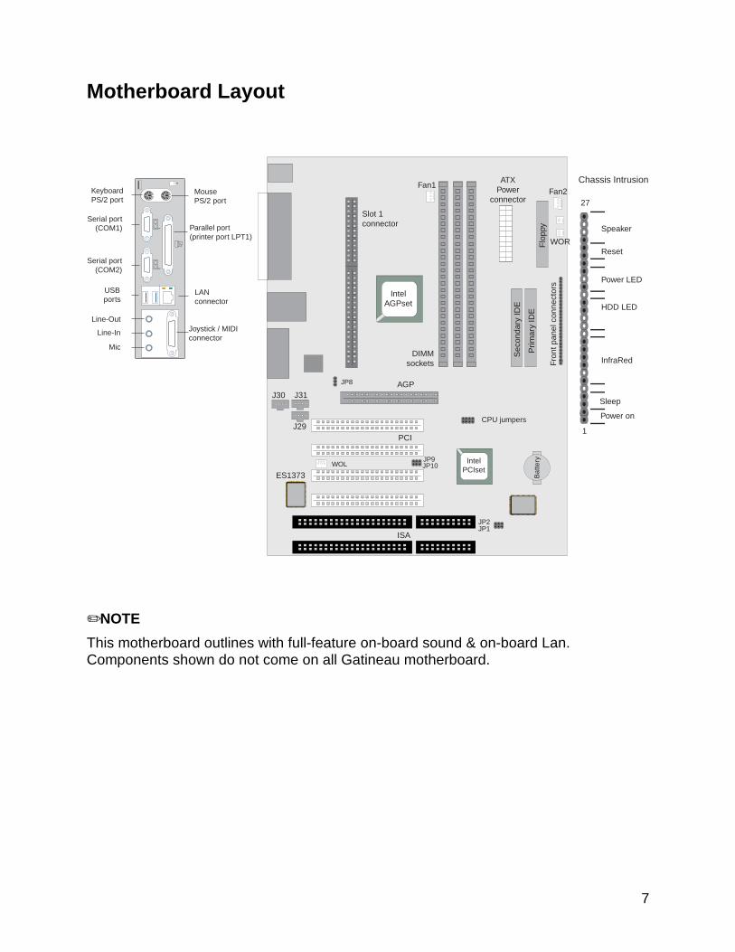
Motherboard Layout
✏NOTE
This motherboard outlines with full-feature on-board sound & on-board Lan.Components shown do not come on all Gatineau motherboard.
AGP
PCI
ISA
J29
J30 J31
12
WOL
JP8
JP2JP1
JP9JP10
IntelAGPset
IntelPCIset
ES1373
1
27
Reset
HDD LED
Speaker
Power LED
InfraRed
Sleep
Power on
WOR
Slot 1connector
ATXPower
connector
DIMMsockets Fr
ont p
anel
con
nect
ors
Prim
ary
IDE
Sec
onda
ry ID
E
Flo
ppy
MousePS/2 port
KeyboardPS/2 port
USBports
Line-In
Mic
Line-Out
Parallel port(printer port LPT1)
Serial port(COM1)
Serial port(COM2)
LANconnector
Joystick / MIDIconnector
CPU jumpers
Bat
tery
Chassis IntrusionFan1
Fan2
8
Central Processing UnitThis motherboard is designed to operate with a single Intel Celeron, Pentium® II, orPentium® III processor. The processor’s VID pins automatically program the voltageregulator on the motherboard to the required processor voltage. In addition, the frontside bus speed (100 MHz and 66 MHz) is automatically selected.
The Intel processors include the following features:
• Intel's highest performance processor, combining the power of the Intel Pentium® IIIprocessor with the capabilities of MMX™ technology and new Katmai instructions.
• Takes advantage of the same high-performance Dual Independent Bus architectureused in the Intel Pentium III processor for high bandwidth and performance.
• Single Edge Contact (S.E.C.) cartridge packaging technology delivers highperformance processing and bus technology to mainstream systems. The cartridgeincludes the processor core, second-level cache, thermal plate, and back cover.
• Optimized for 32-bit applications running on advanced operating systems.
• Data integrity and reliability features include system bus ECC, Fault Analysis,Recovery, and Functional Redundancy Checking.
MemoryThe motherboard has three dual inline memory module (DIMM) sockets. SynchronousDRAM (SDRAM) can be installed in any of the 3 sockets. EDO DIMMs are notsupported. Minimum memory size is 16 MB; maximum memory size is 768 MB. Memorysize can vary between sockets.
The motherboard supports the following memory features:
• 168-pin DIMMs
• 100 or 66 MHz SDRAM
• Non-ECC (64-bit) and ECC (72-bit) memory
• 3.3 V memory only
• Single- or double-sided DIMMs in the following sizes:
DIMM Size Non-ECC Configuration ECC Configuration
16 MB 2 Mbit x 64 2 Mbit x 72
32 MB 4 Mbit x 64 4 Mbit x 72
64 MB 8 Mbit x 64 8 Mbit x 72
128 MB 16 Mbit x 64 16 Mbit x 72
256 MB 32 Mbit x 64 32 Mbit x 72
9
✏NOTE
Processors with 100 MHz front-side bus should be paired only with 100 MHz SDRAM.
Processors with 66 MHz front side bus can be paired with either 66 MHz or 100 MHzSDRAM.
SDRAM
Synchronous DRAM (SDRAM) improves memory performance through memory accessthat is synchronous with the memory clock. This simplifies the timing design andincreases memory speed because all timings are dependent on the number of memoryclock cycles.
✏NOTE
All memory components and DIMMs used with this motherboard must comply with thePC SDRAM specifications. These include the PC SDRAM Specification (memorycomponent specific), the PC Un-buffered DIMM Specification, and the PC SerialPresence Detect Specification. You can access these documents through the Internetat http://www.intel.com/design/pcisets/memory/
ECC Memory
ECC memory detects multiple-bit errors and corrects single-bit errors. When ECCmemory is installed, the BIOS supports both ECC and non-ECC mode. ECC mode isenabled in the Setup program. The BIOS automatically detects if ECC memory isinstalled and provides the Setup option for selecting ECC mode. If any non-ECCmemory is installed, the Setup option for ECC configuration does not appear and ECCoperation is not available.
The following table describes the effect of using Setup to put each memory type in eachsupported mode. Whenever ECC mode is selected in Setup, some performance lossoccurs.
Cache Memory
The Intel microprocessors include 32 KB (16K/16K) non-blocking level one cache andup to 1 MB unified, non-blocking level two cache on the substrate in the Single EdgeConnector (S.E.C.) cartridge. The size of level two cache varies between the Intel
Celeron, Pentium II and Pentium III processors, it could be 0KB, 128KB, 256KB or512 KB.
10
ChipsetThe Intel 440BX PCIset includes a Host-PCI bridge integrated with both an optimizedDRAM controller and an Accelerated Graphics Port (A.G.P.) interface. The I/Osubsystem of the 440BX is based on the PIIX4E, which is a highly integrated PCI-ISA/IDE Accelerator Bridge. This chipset consists of the Intel 82443BX PCI/A.G.P.controller (PAC) and the Intel 82371EB PCI/ISA IDE Xcelerator (PIIX4E) bridge chip.
Intel 82443BX PCI/A.G.P. controller (PAC)
The PAC provides bus-control signals, address paths, and data paths for transfersbetween the processor’s host bus, PCI bus, Accelerated Graphics Port (A.G.P.), andmain memory. The PAC comes in a 492-pin BGA package and features:
• Processor interface control
Support for processor host bus frequencies of 100 MHz or 66 MHz
32-bit addressing
Desktop Optimized GTL+ compliant host bus interface
• Integrated DRAM controller, with support for:
+3.3 V only DIMM DRAM configurations
Up to four double sided DIMMs
Synchronous 100-MHz or 66-MHz SDRAM
SDRAM 64-bit data interface with ECC support
• A.G.P. interface
Complies with the A.G.P. specification (see Section 6.2 for specificationinformation)
Support for +3.3 V PCI-66, A.G.P.-66/133 devices
Synchronous coupling to the host-bus frequency
• PCI bus interface
Complies with the PCI specification Rev 2.1, +5 V 33 MHz interface
Asynchronous coupling to the host-bus frequency
PCI parity generation support
Data streaming support from PCI-to-DRAM
Support for concurrent host, A.G.P., and PCI transactions to main memory
• Data buffering
DRAM write buffer with read-around-write capability
Dedicated host-to-DRAM, PCI0-to-DRAM, and PCI1/A.G.P.-to-DRAM read buffers
A.G.P. dedicated inbound/outbound FIFOs (133/66 MHz), used for temporary datastorage
11
• Power management functions
Support for system suspend/resume (DRAM and power-on suspend)
Compliant with ACPI power management
• SMBus support for desktop management functions
• Support for system management mode (SMM)
Intel 82371EB PCI ISA IDE Xcelerator (PIIX4E)
The PIIX4 is a multifunction PCI device implementing the PCI-to-ISA bridge, PCI IDEfunctionality, Universal Serial Bus (USB) host/hub function, and enhanced powermanagement. The PIIX4E comes in a 324-pin package that features:
• Multifunction PCI-to-ISA bridge
Support for the PCI bus at 33 MHz
Complies with the PCI specification (see Section 6.2 for specification information)
Full ISA bus support
• USB controller
Two USB ports (see Section 6.2 for specification information)
Support for legacy keyboard and mouse
Support for UHCI interface (see Section 6.2 for specification information)
• Integrated dual-channel enhanced IDE interface
Support for up to four IDE devices
PIO Mode 4 transfers at up to 16 MB/sec
Support for Ultra DMA/33 synchronous DMA mode transfers up to 33 MB/sec
Bus master mode with an 8 x 32-bit buffer for bus master PCI IDE burst transfers
• Enhanced DMA controller
Two 8237-based DMA controllers
Support for PCI DMA with three PC/PCI channels and distributed DMA protocols
• Interrupt controller based on 82C59
Support for 15 interrupts
Programmable for edge/level sensitivity
• Power management logic
Sleep/resume logic
Support for wake-on-modem, Wake on LAN technology, and wake on PME
Support for ACPI (see Section 6.2 for specification information)
• Real-time Clock
12
256-byte battery-backed CMOS SRAM
Includes date alarm
• 16-bit counters/timers based on 82C54
Accelerated Graphics Port (A.G.P.)
The Accelerated Graphics Port (A.G.P.) is a high-performance interface for graphic-intensive applications, such as 3D applications. A.G.P. is independent of the PCI busand is intended for exclusive use with graphical-display devices. A.G.P. provides theseperformance features:
• Pipelined-memory read and write operations that hide memory access latency.
• De-multiplexing of address and data on the bus for near 100 percent bus efficiency.
• AC timing for 133 MHz data transfer rates, allowing data throughput of500MBYTES/sec.
• A.G.P. complies with the 66 MHz PCI specification.
Universal Serial Bus (USB)
The motherboard has two USB ports; one USB peripheral can be connected to eachport. For more than two USB devices, an external hub can be connected to either port.The motherboard fully supports the universal host controller interface (UHCI) and usesUHCI-compatible software drivers. USB features include:
• Self-identifying peripherals that can be plugged in while the computer is running.
• Automatic mapping of function to driver and configuration.
• Supports isonchronous and asynchronous transfer types over the same set of wires.
• Supports up to 127 physical devices.
• Guaranteed bandwidth and low latencies appropriate for telephony, audio, and otherapplications.
• Error-handling and fault-recovery mechanisms built into the protocol.
IDE Support
The motherboard has two independent bus-mastering PCI IDE interfaces. Theseinterfaces support PIO Mode 3, PIO Mode 4, ATAPI devices (e.g., CD-ROM), and UltraDMA/33 synchronous-DMA mode transfers. The BIOS supports logical blockaddressing (LBA) and extended cylinder head sector (ECHS) translation modes. TheBIOS automatically detects the IDE device transfer rate and translation mode.
Programmed I/O operations usually require a substantial amount of processorbandwidth. However, in multitasking operating systems, the bandwidth freed by busmastering IDE can be devoted to other tasks while disk transfers are occurring.
13
The motherboard also supports laser servo (LS-120) drives. LS-120 technology allowsthe user to perform read/write operations to LS-120 (120 MB) and conventional 1.44MB and 720 KB diskettes. An optical servo system is used to precisely position a dual-gap head to access the diskette’s 2,490 tracks per inch (tpi) containing up to 120 MB ofdata storage. A conventional diskette uses 135 tpi for 1.44 MB of data storage.
LS-120 drives are ATAPI-compatible and connect to the motherboard’s IDE interface.(LS-120 drives are also available with SCSI and parallel port interfaces.) Some versionsof Windows 95 and Windows NT operating systems recognize the LS-120 drive as abootable device in both 120 MB and 1.44 MB mode.
Connection of an LS-120 drive and a standard 3.5-inch diskette drive is allowed. TheLS-120 drive can be configured as a boot device if selected in the Setup program.
Real-Time Clock, CMOS RAM and Battery
The real-time clock is compatible with DS1287 and MC146818 components. The clockprovides a time-of-day clock and a multi-century calendar with alarm features andcentury rollover. The real-time clock supports 256 bytes of battery-backed CMOSSRAM in two banks that are reserved for BIOS use.
The time, date, and CMOS values can be specified in the Setup program. The CMOSvalues can be returned to their defaults by using the Setup program.
An external coin-cell battery powers the real-time clock and CMOS content. When thecomputer is not plugged into a wall socket, the battery has an estimated life of threeyears. When the computer is plugged in, the 3.3 V standby current from the powersupply extends the life of the battery.
Super I/O ControllerThe motherboard uses the NSC PC87351 controller which features:
• Single diskette drive interface
• ISA Plug-and-Play compatible register set
• Two serial ports
• FIFO support on both serial and diskette interfaces
• One parallel port with ECP and EPP support
• PS/2 style mouse and keyboard interfaces
• Intelligent auto power management, including:
Shadowed write-only registers for ACPI compliance
Programmable wake-up event interface
The Setup program provides configuration options for the I/O controller.
14
Serial Ports
The motherboard has two 9-pin D-Sub serial port connectors located on the back panel.The NS16C550-compatible UARTs support data transfers at speeds up to115.2Kbits/sec with BIOS support.
Parallel Ports
The connector for the multi-mode bi-directional parallel port is a 25-pin D-Sub connectorlocated on the back panel of the motherboard. In the Setup program, there are fouroptions for parallel port operation:
• Compatible (standard mode)
• Bi-directional
• Bi-directional Enhanced Parallel Port (EPP). A driver from the peripheralmanufacturer is required for operation.
• Bi-directional high-speed Extended Capabilities Port (ECP)
Floppy disk Controller
In the Setup program, the floppy interface can be configured for the following floppydrive capacities and sizes:
• 360 KB, 5.25-inch
• 1.2 MBYTES, 5.25-inch
• 720 KB, 3.5-inch
• 1.44 MBYTES, 3.5-inch
• 2.88 MBYTES, 3.5-inch
Keyboard and Mouse Interface
PS/2 keyboard and mouse connectors are located on the back panel. The 5 V lines tothese connectors are protected with a PolySwitch† circuit that, like a self-healing fuse,re-establishes the connection after an over-current condition is removed.
Power to the computer should be turned off before a keyboard or mouse is connectedor disconnected.
The keyboard controller also supports the hot-key sequence <Ctrl><Alt><Del> for asoftware reset. This key sequence resets the computer’s software by jumping to thebeginning of the BIOS code and running the Power-On Self Test (POST).
Infrared Support
On the front panel I/O connector (pins 6-11), there are six pins that support HewlettPackard HSDL-1000 compatible infrared (IR) transmitters and receivers. In the Setupprogram, Serial Port 2 can be directed to a connected IR device. The connection can
15
be used to transfer files to or from portable devices like laptops, PDAs, and printers.The Infrared Data Association (IrDA) specification supports data transfers of up to 115Kbaud at a distance of 1 meter.
BIOS System SupportBIOS, an acronym for Basic Input Output System, acts as the first link betweenhardware and software in coordinating the startup configuration of computers. Plug andplay ready, AWARD BlOS automatically configures the computer’s hard drives, diskdrives, processors, chipsets, memory, and boot-up of the operating system.
The system BIOS, from AWARD, provides ISA PnP and PCI PnP compatibility. TheBIOS is contained in a flash memory device. The BIOS provides the power-on self test(POST), the system Setup program, a PCI and IDE auto-configuration.
The system BIOS is always shadowed. Shadowing allows any BIOS routines to beexecuted from fast 32-bit onboard DRAM instead of from the slower 8-bit flash device.
1. Plug and Play Rev 1.0A support.
2. Boot Block Protection.
3. Auto detects Pipeline Burst SRAM and Cache size, IDE mode type and size.
4. Supports APM 1.2.
5. Supports DMI 2.0.
6. Supports USB.
7. Supports Booting from a Floppy drive, IDE device, CD-ROM, SCSI, Floptical orNetwork.
8. 1MBYTES/2MBYTES flash EEPROM for easy BIOS upgrade.
PCI IDE
1. “Ultra DMA/33” Synchronous DMA IDE support.
2. Meets Microsoft requirement for PC97/PC98.
3. Fully compatible with PCI spec.V2.1.
4. Supports PCI Bus Mastering.
5. Supports Mode 3 and Mode 4 for Enhanced IDE specification.
6. Supports Multi-word DMA mode 0,1,2.
7. Supports PCI burst Read/Write.
8. Supports Primary and Secondary IDE for a total of 4 drives.
9. IDE CD-ROM support.
16
PCI Auto-configuration
The PCI auto-configuration works in conjunction with the Setup program to supportusing PCI add-in boards in the system. When you turn on the system power afterinstalling a PCI board, the BIOS automatically configures interrupts, DMA channels, I/Ospace, and so on. Since PCI add-in boards use the same interrupt resources as ISAadd-in boards, you must specify the interrupts used by non PnP ISA boards in theSetup program. Chapter 3 tells how to use the Setup program. The PCI auto-configuration program complies with version 2.1 of the PCI BIOS specification.
IDE Auto-configuration
When an IDE drive is installed in the system, the IDE auto-configuration functionautomatically detects and configures the drive for operation in the system. This functioneliminates the need to enter the Setup program after you install an IDE drive.
ISA Plug and Play Capability
This provides auto-configuration of Plug and Play ISA cards and resource managementfor legacy (non Plug and Play) ISA cards.
Universal Serial Bus (USB) Support
The USB technology enables users to quickly and easily attach and reconfigure a widerange of peripheral devices, from keyboards to printers to telephony devices. Withcomprehensive support for both USB host controllers and USB devices, AWARD BIOSoffers the ability to fully utilize USB technology. The motherboard features two USBports as a factory installed option. The ports permit the direct connection of two USBperipherals without an external hub. If more devices are required, an external hub canbe connected to either of the built-in ports This motherboard fully supports the standardUniversal Host Controller Interface (UHCI) and uses standard software drivers that areUHCI compatible. Features of the USB include:
• Self-identifying, hot pluggable peripherals.
• Automatic Mapping of function to driver and configuration.
• Support for Isochronous and Asynchronous transfer types over the same set ofwires.
• Support for up to 127 physical devices.
• Guaranteed bandwidth and low latencies appropriate for telephony, audio, and otherapplications.
Error handling and fault recovery mechanisms built into protocol.
17
BIOS Upgrades
Because the BIOS is stored in a flash memory device, you can easily upgrade the BIOSwithout having to disassemble the system. The flash upgrade process can be done byrunning a utility from a diskette or hard disk, or over a network.
WARNING
For information about the latest BIOS update for the Gatineau, contact yourservice representative.
Expansion SlotsThis motherboard has two 16-bit ISA slots, four PCI expansion slots and one AGP slot.
PCI Slots:
The PCI bus transfers data at 132 MB/second. Part of the reason for high transfer ratesis the PCI bus can operate concurrently with the processor bus; it doesn’t override it.The CPU can be processing data in an external cache while the PCI bus is busytransferring information between other parts of the system. Another key feature of thePCI bus is it’s plug and play capabilities. This eliminates the need for jumper and dipswitches for configuring a PCI card.
The PCI slots on the Gatineau motherboard are numbered 1-4, with 1 being closest tothe AGP slot. All PCI slots are fully functional bus-mastering slots.
PCI 1:
This slot shares the PCI Interrupt used by the AGP slot.
PCI 2:
This slot shares the PCI Interrupt used by the integrated on-board sound
PCI 3:
This slot shares the PCI interrupt used by the integrated on-board LAN.
PCI 4:
This slot does not share the PCI interrupt with any slots and on-board devices.
Hardware MonitorThe optional hardware monitor subsystem provides the instrumentation capabilities.The features of the hardware monitor subsystem include:
• Support for an optional chassis intrusion sensor or mechanical switch.
• An integrated ambient temperature sensor.
18
• Fan speed sensors, which monitor the fan 1 and fan 2 connectors (see motherboardlayout for the location of these connectors).
• Power supply voltage monitoring to detect levels above or below acceptable values.
When suggested ratings for temperature, fan speed, or voltage are exceeded, aninterrupt is activated. The hardware monitor component connects to the SMBUS.
Onboard LAN (Optional)The optional onboard LAN for the Gatineau motherboard is driven by the Intel 82559chipset. The Intel82559 is a 10/100 MBps PCI Ethernet LAN Controller. It automaticallydetects between 10 Base-T or 100 Base-TX Fast Ethernet connections. This function isa manufacturing option, if it is not installed the JP3 jumper will also NOT be installed.
The LAN LEDs which are mounted next to the LAN connector indicate the following:
Yellow LED (Speed) On status indicates a 100 MBps connection.
Off status indicates a 10 MBps connection.
Green LED (ACT/LINK) Indicates there is activity on the LAN.
Indicates if the LAN cable is connected (linked).
Remote reset capabilities are possible from a remote peer or server using the LANDeskClient Manager and service layers (when available)
Onboard Sound (Optional)The onboard sound is powered by the Creative Ensoniq AudioPCI ES1373 chipset. Formusic playback, the Ensoniq synthesis engine provides 32 voices of great wave-tablesounds. Now the instruments sound just like their real life counterparts, not a poorfacsimile. Utilizing the PCI bus, the Ensoniq AudioPCI uses far less CPU overhead thantraditional sound cards. This equates to better performance in multimedia titles andterrific audio quality with very little processor usage.
It supports three rear jacks and three connectors on the motherboard. Refer to thelayout diagram for the location of each one.
Rear jacks:
Line-in
Line-out
Microphone
Joystick/MIDI connector
Motherboard connectors:
CD audio input – J29 (green connector)
19
Wake On LAN Header (WOL)The WOL header is used to implement the Wake on LAN feature when the onboardLAN is not installed. Connect this header to a PCI LAN adapter that supports the Wakeon LAN feature. The adapter monitors network traffic. When the adapter detects a‘Magic Packet’, it asserts a signal through the Wake on LAN header to wake up thecomputer. This signal can wake up the computer only when the AC power cord is stillplugged into the wall socket and the computer is turned off using the Standby Powerbutton.
Note: WOL requires an ATX power supply that can supply 720 mA current at the5V standby output.
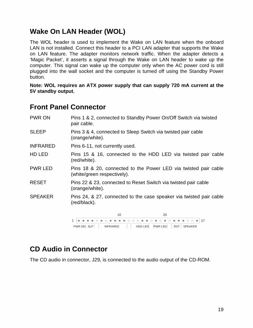
Front Panel ConnectorPWR ON Pins 1 & 2, connected to Standby Power On/Off Switch via twisted
pair cable.
SLEEP Pins 3 & 4, connected to Sleep Switch via twisted pair cable(orange/white).
INFRARED Pins 6-11, not currently used.
HD LED Pins 15 & 16, connected to the HDD LED via twisted pair cable(red/white).
PWR LED Pins 18 & 20, connected to the Power LED via twisted pair cable(white/green respectively).
RESET Pins 22 & 23, connected to Reset Switch via twisted pair cable(orange/white).
SPEAKER Pins 24, & 27, connected to the case speaker via twisted pair cable(red/black).
CD Audio in ConnectorThe CD audio in connector, J29, is connected to the audio output of the CD-ROM.
1 27
PWR ON SLP INFRARED HDD LED PWR LED RST SPEAKER
10 20
20
Fan ConnectorsTwo fan connectors are provided, Fan 1 is recommended for the CPU heat-sink fan,Fans 2 can be used for any other case or heat-sink fan, however fan 2 does not havethe fan speed monitoring capability.
The pin assignment for these connectors are as follows:
Pin 1 – Ground.
Pin 2 - +12V.
Pin 3 – Sensor
Main Power ConnectorWhen used with an ATX-compliant power supply that supports remote power on/off, themotherboard can turn off the system power through software control.
To enable soft-off control in software, advanced power management must be enabledin the Setup program and in the operating system. When the system BIOS receives thecorrect APM command from the operating system, the BIOS turns off power to thecomputer.
With soft-off enabled, if power to the computer is interrupted by a power outage or adisconnected power cord, when power resumes, the computer returns to the powerstate it was in before power was interrupted (on or off).
Management Extension HardwareThe optional Management Extension component (Analog Device AMD9240A) providesthe instrumentation capabilities designed to reduce the total cost of owning a PC whenused with Intel LANDesk Client Manager. Feature include:
• Integrated temperature monitoring.
• Fan speed monitoring.
• Power supply voltage monitoring to detect levels above or below acceptable values.
• Registers for storing POST hardware test results and error codes.
• Chassis Intrusion - This is carried out by the installation of a light sensitive device onthe motherboard (close to the BIOS). This will detect the presence of light if thechassis cover is removed. Alternatively, a header (close to the BIOS) is installed onthe motherboard for the connection of a micro switch to detect chassis intrusion.
When suggested ratings for temperature, fan speed, or voltage are exceeded, aninterrupt is activated to report the status.
21
LS-120 SupportLS-120 MB Diskette technology enables users to store 120 MB of data on a single, 3.5Inch removable diskette. LS-120 technology is backward (both read and write)compatible with 1.44 MB and 720 KB DOS-formatted diskettes and is supported byWindows 95/98 and Windows NT operating systems.
The Gatineau motherboard allows connection of an LS-120 compatible drive and astandard 3.5-inch diskette drive. The LS-120 drive can be configured as a boot device,if selected in the BIOS setup utility.
System SecurityThe BIOS provides Supervisor level and User level passwords that you can enablethrough the Setup program.
Chassis Intrusion Detection is also available as a manufacturing option.
22
2.Installation and Settings
CAUTION
Electrostatic discharge (ESD) can damage components. Perform the proceduresdescribed in this chapter only at an ESD workstation. If such a station is notavailable, you can provide some ESD protection by wearing an anti-static wriststrap and attaching it to a metal part of the computer.
Jumper SettingsThe motherboard contains configuration jumpers that make it possible to change thesystem configuration. Normally, the only time you will ever change a jumper is if youneed to:
• Change the system operating speed
• Clear CMOS
• Clear Password
• Change the Onboard LAN Power Supply voltage source
✏NOTE
A jumper is a small plastic-encased conductor that slips over jumper pins. To change ajumper setting, use a pair of fine needle-nosed pliers to remove the jumper from itscurrent location and slide it onto the new pins to obtain the desired setting.
CAUTION
Do not squeeze the pliers or other tool you use to remove a jumper, or you might bendor break the pins.
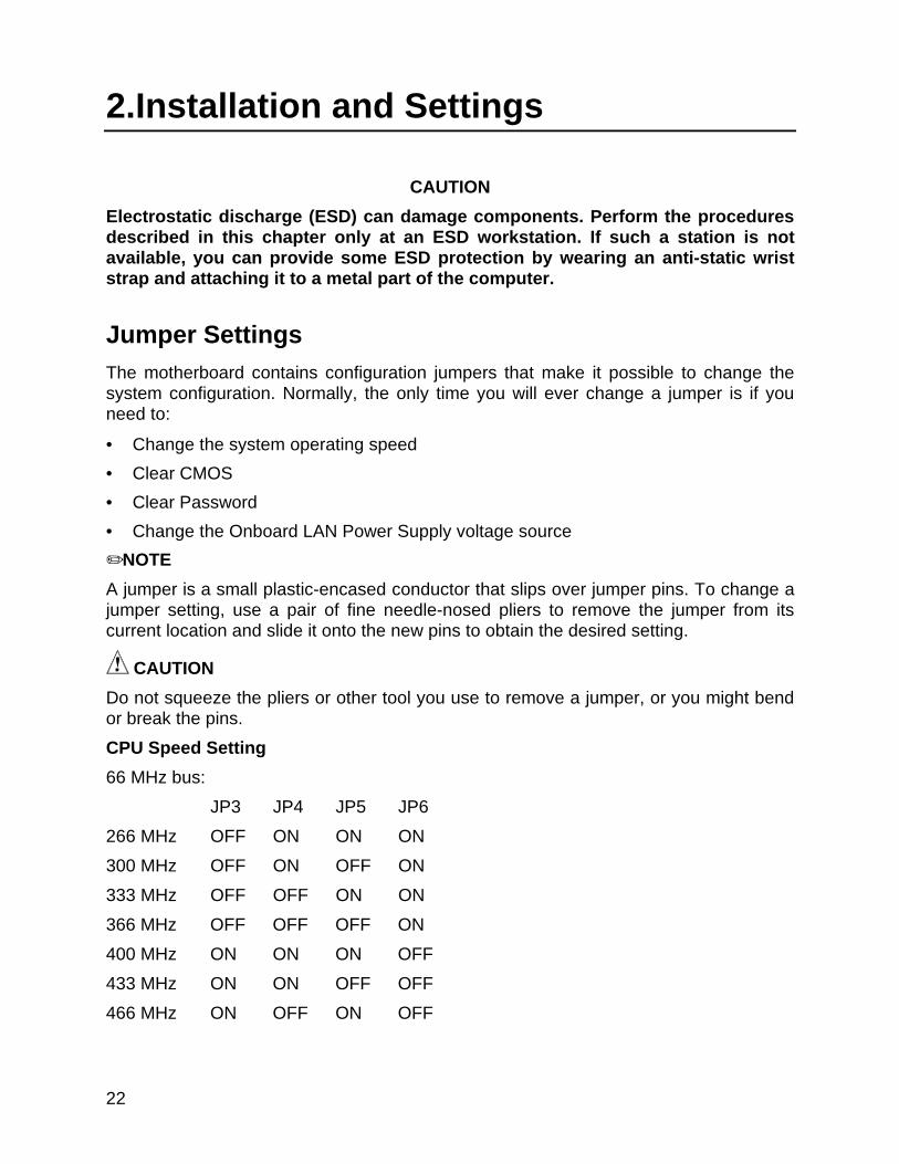
CPU Speed Setting
66 MHz bus:
JP3 JP4 JP5 JP6
266 MHz OFF ON ON ON
300 MHz OFF ON OFF ON
333 MHz OFF OFF ON ON
366 MHz OFF OFF OFF ON
400 MHz ON ON ON OFF
433 MHz ON ON OFF OFF
466 MHz ON OFF ON OFF

23
100 MHz bus:
JP3 JP4 JP5 JP6
350 MHz ON OFF OFF ON
400 MHz OFF ON ON ON
450 MHz OFF ON OFF ON
500 MHz OFF OFF ON ON
550 MHz OFF OFF OFF ON
Onboard LAN Power Supply Voltage Source – JP8:
JP8
3.3V 1-2
Standby 3.3V 2-3*
Clear CMOS – JP9:
JP9
Normal 1-2*
Clear CMOS 2-3
To clear the CMOS do the following:
• Power down the system.
• Remove the system cover to access the motherboard.
• Change the setting of JP9 to 2-3 (see the motherboard layout for it’s location).
• Turn on the system, wait until you see video and turn the system off again.
• Change the setting of JP9 back to 1-2 (the default).
• Replace the system cover.
• Turn on the system and change the BIOS settings according to your preferences.
Clear Password – JP10:
JP10
Normal 1-2*
Clear Password 2-3
24
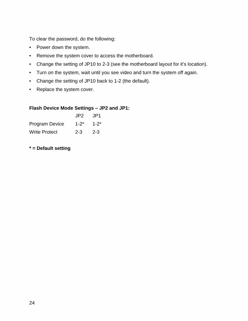
To clear the password, do the following:
• Power down the system.
• Remove the system cover to access the motherboard.
• Change the setting of JP10 to 2-3 (see the motherboard layout for it’s location).
• Turn on the system, wait until you see video and turn the system off again.
• Change the setting of JP10 back to 1-2 (the default).
• Replace the system cover.
Flash Device Mode Settings – JP2 and JP1:
JP2 JP1
Program Device 1-2* 1-2*
Write Protect 2-3 2-3
* = Default setting
25
CPU Installation
Upgrading the CPU
Seanix computers are equipped with Intel® CPUs only. The installation proceduresshown below are for the Intel® Pentium and Intel® Celeron processors.
Intel Pentium II, Pentium III and Celeron processors are of the modular type thatplug into a slot on the motherboard, called slot 1. Refer to the layout diagram for thelocation of slot 1.
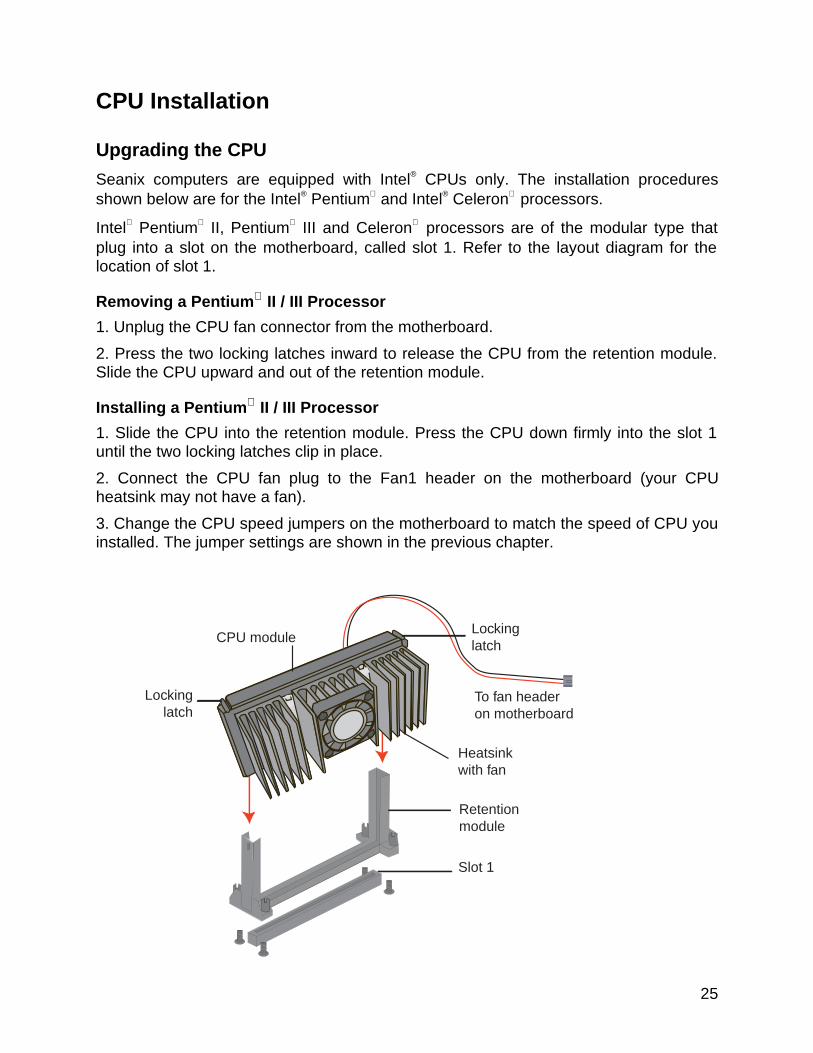
Removing a Pentium II / III Processor
1. Unplug the CPU fan connector from the motherboard.
2. Press the two locking latches inward to release the CPU from the retention module.Slide the CPU upward and out of the retention module.
Installing a Pentium II / III Processor
1. Slide the CPU into the retention module. Press the CPU down firmly into the slot 1until the two locking latches clip in place.
2. Connect the CPU fan plug to the Fan1 header on the motherboard (your CPUheatsink may not have a fan).
3. Change the CPU speed jumpers on the motherboard to match the speed of CPU youinstalled. The jumper settings are shown in the previous chapter.
To fan headeron motherboard
CPU module
Heatsinkwith fan
Retentionmodule
Slot 1
Lockinglatch
Lockinglatch
26
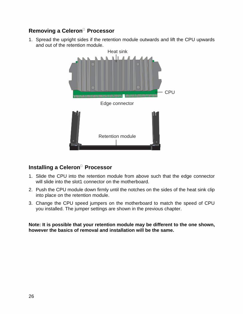
Removing a Celeron Processor
1. Spread the upright sides if the retention module outwards and lift the CPU upwardsand out of the retention module.
Installing a Celeron Processor
1. Slide the CPU into the retention module from above such that the edge connectorwill slide into the slot1 connector on the motherboard.
2. Push the CPU module down firmly until the notches on the sides of the heat sink clipinto place on the retention module.
3. Change the CPU speed jumpers on the motherboard to match the speed of CPUyou installed. The jumper settings are shown in the previous chapter.
Note: It is possible that your retention module may be different to the one shown,however the basics of removal and installation will be the same.
Edge connector
CPU
Heat sink
Retention module
27
System Memory InstallationYou can install from 16 MB to 768 MB of memory in the motherboard DIMM sockets.The board has DIMM sockets arranged as banks 0, I, and 2. The motherboard supportsthe following memory features:
• 168-pin SDRAM DIMMs.
• 100 MHz or 66 MHz unbuffered SDRAM DIMMs.
• Non-ECC (64-bit) or ECC (72-bit) memory.
• 16 MB, 32 MB, 64 MB, 128 and 256 MB modules.
When adding memory, follow these guidelines:
• You can install DIMMs in any of the three banks.
• You can use different size DIMMs in different banks.
• The BIOS detects the size of installed memory.
• For ECC operation to be available, all installed memory must be ECC and you mustenable the ECC Configuration feature in the Setup program (see chapter 3).
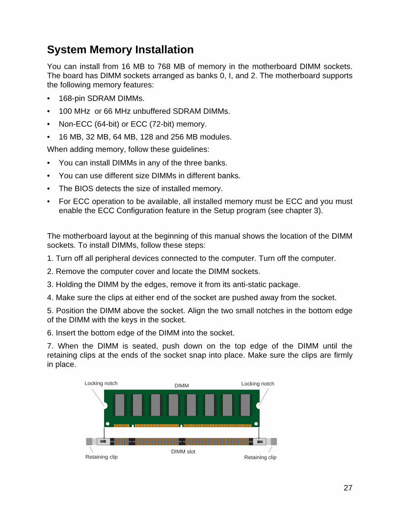
The motherboard layout at the beginning of this manual shows the location of the DIMMsockets. To install DIMMs, follow these steps:
1. Turn off all peripheral devices connected to the computer. Turn off the computer.
2. Remove the computer cover and locate the DIMM sockets.
3. Holding the DIMM by the edges, remove it from its anti-static package.
4. Make sure the clips at either end of the socket are pushed away from the socket.
5. Position the DIMM above the socket. Align the two small notches in the bottom edgeof the DIMM with the keys in the socket.
6. Insert the bottom edge of the DIMM into the socket.
7. When the DIMM is seated, push down on the top edge of the DIMM until theretaining clips at the ends of the socket snap into place. Make sure the clips are firmlyin place.
DIMM Locking notchLocking notch
Retaining clipRetaining clipDIMM slot
28
8. Replace the computer cover.
9. If you installed a DIMM with ECC memory, start the computer and use the ECCConfiguration feature in Setup to enable the use of ECC.
Removing Memory
To remove a DIMM, follow these steps:
1. Gently spread the retaining clips at each end of the socket. The DIMM pops out ofthe socket.
2. Hold the DIMM by the edges, lift it away from the socket, and store it in an anti-staticpackage.
3. Reinstall and reconnect any parts you removed or disconnected to reach the DIMMsockets.
Battery ReplacementWhen your computer is turned off, a lithium battery keeps the time-of-day clock and thevalues in CMOS RAM current.
The battery should last about seven years. When the battery begins to die, it losesvoltage; when the voltage drops below a certain level, the Setup program settingsstored in CMOS RAM (for example, the date and time) might not be accurate. Replacethe battery with an equivalent one.
If your local ordinances permit, you may dispose of individual batteries as normal trash.Do not expose batteries to excessive heat or fire. Keep all batteries away from children.
CAUTION
Danger of explosion if the battery is incorrectly replaced. Replace only with the same orequivalent type recommended by the equipment manufacturer. Discard used batteriesaccording to manufacturer’s instructions.
Expansion Card InstallationThe computer system should be switched off and the power cord removed beforeinstalling any expansion cards into the system. Failure to do so may cause severedamage to both your motherboard and expansion cards.
Before installing an expansion card, read it’s documentation regarding any hardware orsoftware settings that may be required to set up your specific card.
• Set any necessary jumpers on the expansion card.
29
• Remove your computer system’s cover.
• Identify the type of slot where the expansion card will be installed and isolate one ofthe vacant slots for your card.
• Remove the blanking bracket for that slot and retain for possible future use.
• Carefully align the cards edge connector with the motherboard slot and press downfirmly to seat the card in the slot, a rocking motion usually makes this easier.
• Secure the cards’ back-plate with the screw you removed earlier.
• Replace the computer system’s cover.
• Plug in the power cord and proceed to install any drivers or software needed for thatcard.
30
3.Using the BIOS Setup ProgramThis chapter tells how to use the Setup program that is built into the BIOS. The Setupprogram makes it possible to change configuration information (such as the types ofperipherals that are installed) and the boot-up sequence for the system. The Setupinformation is stored in CMOS random access memory (RAM) and is backed up by abattery when power is off.
Record the Setup Configuration
To make sure you have a reference to the Setup values for your system, werecommend you to write down the current settings and keep this record up-to-date.
AWARD BIOS Setup Menu Overview
The AWARD BIOS Setup program is easy to use and can be controlled by thekeyboard. Enter the AWARD BIOS Setup main menu as follows:
1. Turn on or reboot your system.
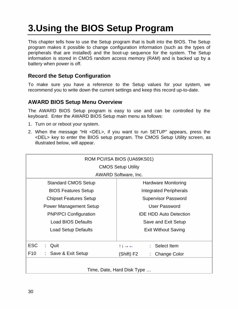
2. When the message “Hit <DEL>, if you want to run SETUP” appears, press the<DEL> key to enter the BIOS setup program. The CMOS Setup Utility screen, asillustrated below, will appear.
ROM PCI/ISA BIOS (UA69KS01)
CMOS Setup Utility
AWARD Software, Inc.
Standard CMOS Setup
BIOS Features Setup
Chipset Features Setup
Power Management Setup
PNP/PCI Configuration
Load BIOS Defaults
Load Setup Defaults
Hardware Monitoring
Integrated Peripherals
Supervisor Password
User Password
IDE HDD Auto Detection
Save and Exit Setup
Exit Without Saving
ESC : Quit
F10 : Save & Exit Setup
↑↓→← : Select Item
(Shift) F2 : Change Color
Time, Date, Hard Disk Type …
31
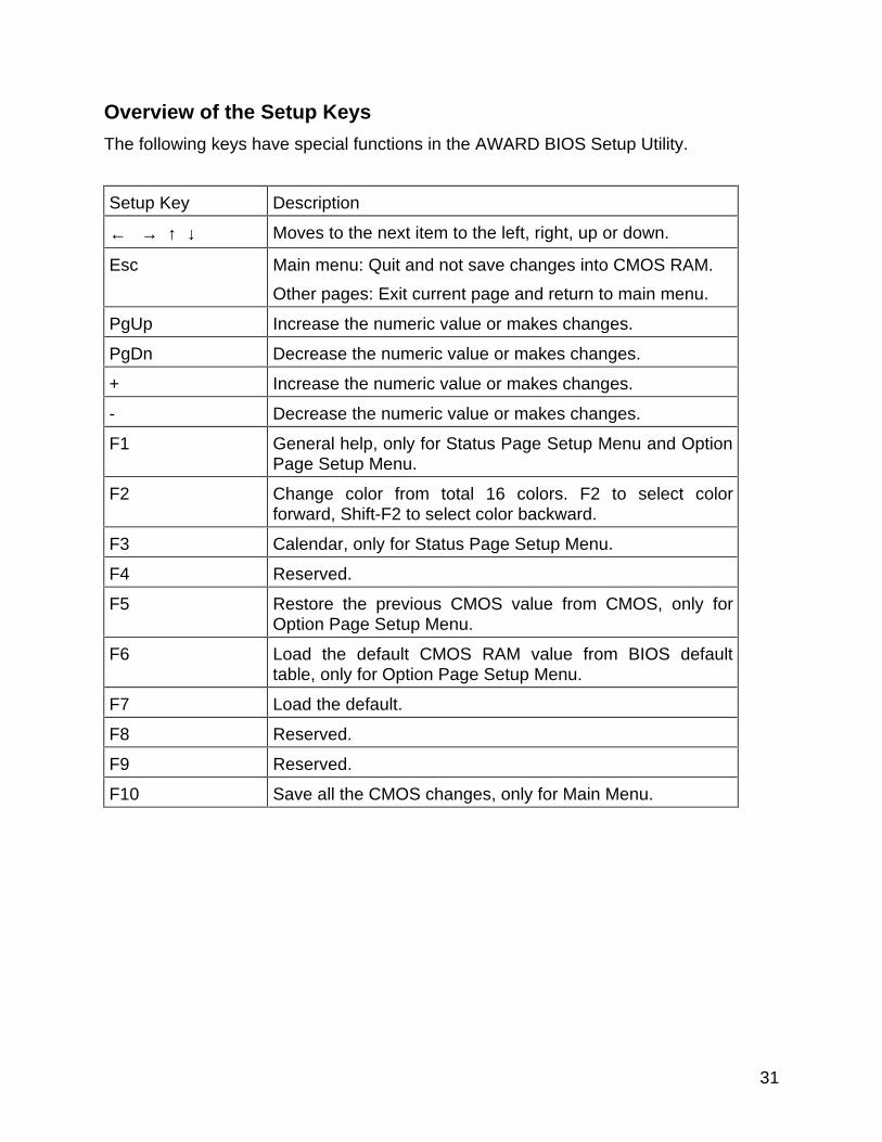
Overview of the Setup Keys
The following keys have special functions in the AWARD BIOS Setup Utility.
Setup Key Description
← → ↑ ↓ Moves to the next item to the left, right, up or down.
Esc Main menu: Quit and not save changes into CMOS RAM.
Other pages: Exit current page and return to main menu.
PgUp Increase the numeric value or makes changes.
PgDn Decrease the numeric value or makes changes.
+ Increase the numeric value or makes changes.
- Decrease the numeric value or makes changes.
F1 General help, only for Status Page Setup Menu and OptionPage Setup Menu.
F2 Change color from total 16 colors. F2 to select colorforward, Shift-F2 to select color backward.
F3 Calendar, only for Status Page Setup Menu.
F4 Reserved.
F5 Restore the previous CMOS value from CMOS, only forOption Page Setup Menu.
F6 Load the default CMOS RAM value from BIOS defaulttable, only for Option Page Setup Menu.
F7 Load the default.
F8 Reserved.
F9 Reserved.
F10 Save all the CMOS changes, only for Main Menu.
32
Standard CMOS Setup
Date (mm : dd : yy) : Wed, Mar 31 1999
Time (hh : mm : ss) : 13 : 1 : 28
HARD DISKS TYPE SIZE CYLS HEAD PRECOMP LANDZ SECTOR MODE
Primary Master : Auto 0 0 0 0 0 0 Auto
Primary Slave : Auto 0 0 0 0 0 0 Auto
Secondary Master : Auto 0 0 0 0 0 0 Auto
Secondary Slave : Auto 0 0 0 0 0 0 Auto
Drive A : 1.44M, 3.5 in.
Drive B : None
Video : EGA/VGA
Halt On : All, But Keyboard
Base Memory : 640K
Extended Memory : 64512K
Other Memory : 384K
Total Memory : 65536K
ESC : Quit ↑↓→← : Select Item PU/PD/+/- : Modify
F1 : Help (Shift) F2:Change Color
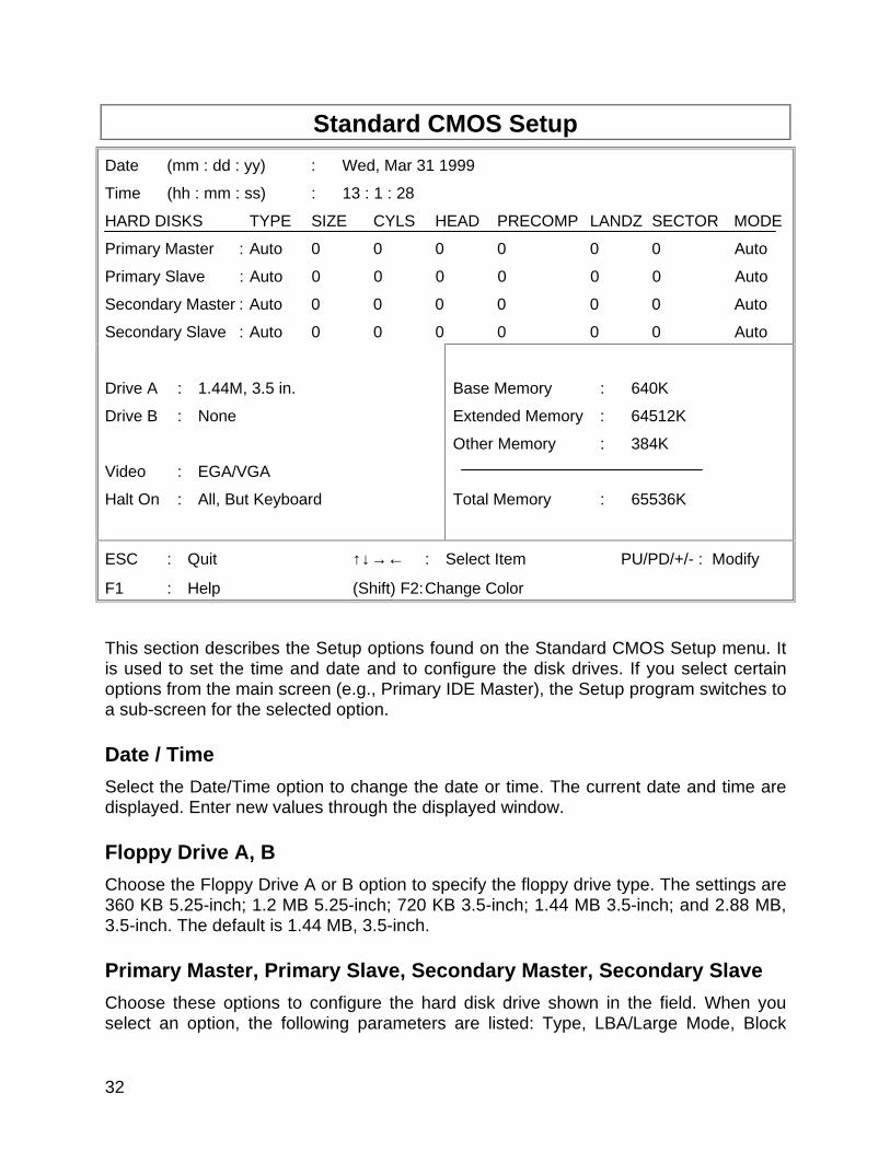
This section describes the Setup options found on the Standard CMOS Setup menu. Itis used to set the time and date and to configure the disk drives. If you select certainoptions from the main screen (e.g., Primary IDE Master), the Setup program switches toa sub-screen for the selected option.
Date / Time
Select the Date/Time option to change the date or time. The current date and time aredisplayed. Enter new values through the displayed window.
Floppy Drive A, B
Choose the Floppy Drive A or B option to specify the floppy drive type. The settings are360 KB 5.25-inch; 1.2 MB 5.25-inch; 720 KB 3.5-inch; 1.44 MB 3.5-inch; and 2.88 MB,3.5-inch. The default is 1.44 MB, 3.5-inch.
Primary Master, Primary Slave, Secondary Master, Secondary Slave
Choose these options to configure the hard disk drive shown in the field. When youselect an option, the following parameters are listed: Type, LBA/Large Mode, Block
33
Mode, 32Bit Mode, and PIO Mode. Use the cursor to highlight “Type” and then choose“Auto” or other options. If you choose “Auto”, the BIOS will automatically detect the typeof HDD before booting the operating system. You can press <enter> again, then theBIOS will show the complete parameters of HDD type.
The BlOS automatically detects the IDE drive parameters (including ATAPI CD-ROMdrives) and displays them. Click on the OK button to accept these parameters Or youcan set the parameters manually if you are absolutely certain that you know the correctIDE drive parameters.
Click on LBA/Large Mode and choose ‘On’ to enable support for IDE drives withcapacities greater than 528 MB.
Click on Block Mode and choose ‘On’ to support IDE drives that use Block Mode.
Click on 32Bit Mode and click on ‘On’ to support IDE drives that permit 32-bit accesses.
Click on PlO Mode to select the IDE Programmed I/O mode. PIO programming alsoworks with ATAPI CD-ROM drives. The settings are Auto, 0, 1, 2, 3, 4, or 5. Click on‘Auto’ to allow the BIOS to automatically find the PIO mode that the IDE drive beingconfigured uses. If you select 0-5 you must make absolutely certain that you areselecting the PIO mode supported by the IDE drive being configured.
Configuring a CD-ROM Drive Select the appropriate drive icon (Pri Master, Pri Slave,Sec Master, or Sec Slave). Choose the Type parameter and select CDROM. You canboot the computer from a CD-ROM drive. You can also choose Auto and let the BIOSautomatically set the correct drive parameters.
34
BIOS Features Setup
Virus Warning : Disabled
CPU Internal Cache : Enabled
External Cache : Enabled
CPU L2 Cache ECC Checking : Enabled
Quick Power On Self Test : Disabled
Boot From LAN First : Disabled
Boot Sequence : A, C, SCSI
Swap Floppy Drive : Disabled
Boot Up Floppy Seek : Enabled
Hard Disk Write Protect : Disabled
Floppy Disk Access Control : R/W
Boot Up Numlock Status : On
Gate A20 Option : Fast
Typematic Rate Setting : Disabled
Typematic Rate (Chars/Sec) : 6
Typematic Delay (Msec) : 250
Video BIOS Shadow : Enabled
C8000-CBFFF Shadow : Disabled
CC000-CFFFF Shadow : Disabled
D0000-D3FFF Shadow : Disabled
D4000-D7FFF Shadow : Disabled
D8000-DBFFF Shadow : Disabled
DC000-DFFFF Shadow : Disabled
Security Option : Setup
PCI/VGA Palette Snoop : Disabled
OS Select For DRAM > 64MB : Non-OS2
HDD SMART capability : Enabled
Report No FDD For Win 95 : Yes
ESC : Quit ↑↓→← : Select Item
F1 : Help PU/PD/+/- : Modify
F5 : Old Values (Shift) F2 : Color
F6 : Load BIOS Defaults
F7 : Load Setup Defaults
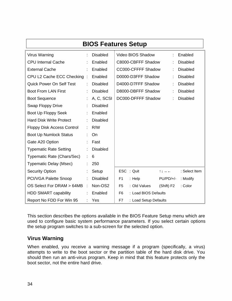
This section describes the options available in the BIOS Feature Setup menu which areused to configure basic system performance parameters. If you select certain optionsthe setup program switches to a sub-screen for the selected option.
Virus Warning
When enabled, you receive a warning message if a program (specifically, a virus)attempts to write to the boot sector or the partition table of the hard disk drive. Youshould then run an anti-virus program. Keep in mind that this feature protects only theboot sector, not the entire hard drive.
35
Note: Many disk diagnostic programs that access the boot sector table cantrigger the virus warning message. If you plan to run such a program, werecommend that you first disable the virus warning.
CPU Internal Cache / External Cache
Cache memory is additional memory that is much faster than conventional DRAM.CPUs from 486-type on up contain internal cache memory, and most, but not all,modern PCs have additional external cache memory. When the CPU requests data, thesystem transfers the requested data from the main DRAM into cache memory, for evenfaster access by the CPU.
CPU L2 Cache ECC Checking
When you select Enabled, memory checking is enable when the external cachecontains ECC SRAMs.
Quick Power On Self Test
Select Enabled to reduce the amount of time required to run the power-on self-test(POST). A quick POST skips certain steps. We recommend that you normally disablequick POST. Better to find a problem during POST than lose data during your work.
Boot From LAN First
When Enabled, the BIOS attempts to boot from a LAN boot image before it attempts toboot from a local storage device.
Boot Sequence
The original IBM PCs loaded the DOS operating system from drive A (floppy disk), soIBM PC-compatible systems are designed to search for an operating system first ondrive A, and then on drive C (hard disk). However, modern computers usually load theoperating system from the hard drive, and may even load it from a CD-ROM drive.
Boot Up Floppy Seek
When Enabled, the BIOS tests (seeks) floppy drives to determine whether they have 40or 80 tracks. Only 360-KB floppy drives have 40 tracks; drives with 720 KB, 1.2 MB,and 1.44 MB capacity all have 80 tracks. Because very few modern PCs have 40-trackfloppy drives, we recommend that you set this field to Disabled to save time.
Boot Up NumLock Status
Toggle between On or Off to control the state of the NumLock key when the systemboots. When toggled On, the numeric keypad generates numbers instead of controllingcursor operations.
36
Swap Floppy Drive
This field is effective only in systems with two floppy drives. Selecting Enabled assignsphysical drive B to logical drive A, and physical drive A to logical drive B.
Gate A20 Option
Gate A20 refers to the way the system addresses memory above 1 MB (extendedmemory). When set to Fast, the system chipset controls Gate A20. When set to Normal,a pin in the keyboard controller controls Gate A20. Setting Gate A20 to Fast improvessystem speed, particularly with OS/2 and Windows.
Typematic Rate Setting
When Disabled, the following two items (Typematic Rate and Typematic Delay) areirrelevant. Keystrokes repeat at a rate determined by the keyboard controller in yoursystem. When Enabled, you can select a typematic rate and typematic delay.
Typematic Rate (Chars/Sec)
When the typematic rate setting is enabled, you can select a typematic rate (the rate atwhich character repeats when you hold down a key) of 6, 8, 10,12, 15, 20, 24 or 30characters per second.
Typematic Delay (Msec)
When the typematic rate setting is enabled, you can select a typematic delay (the delaybefore key strokes begin to repeat) of 250, 500, 750 or 1000 milliseconds.
Security Option
If you have set a password, select whether the password is required every time theSystem boots, or only when you enter Setup.
PCI/VGA Palette Snoop
Leave this field at Disabled.
OS Select for DRAM > 64MB
Select OS2 only if you are running OS/2 operating system with greater than 64 MB ofRAM on your system.
HDD S.M.A.R.T capability
SMART is an acronym for Self Monitoring Analysis and Reporting Technology system.SMART is a hard drive self diagnostic feature available on some IDE hard drives.
37
Report No FDD For WIN 95
Select yes to release IRQ6 when the system contains no floppy drive, for compatibilitywith Windows 95 logo certification. In the integrated peripherals screen, select Disabledfor the Onboard FDC Controller field.
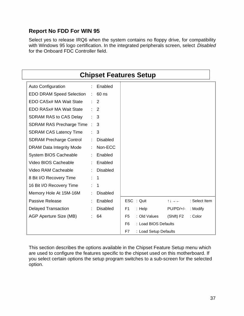
Chipset Features Setup
Auto Configuration : Enabled
EDO DRAM Speed Selection : 60 ns
EDO CASx# MA Wait State : 2
EDO RASx# MA Wait State : 2
SDRAM RAS to CAS Delay : 3
SDRAM RAS Precharge Time : 3
SDRAM CAS Latency Time : 3
SDRAM Precharge Control : Disabled
DRAM Data Integrity Mode : Non-ECC
System BIOS Cacheable : Enabled
Video BIOS Cacheable : Enabled
Video RAM Cacheable : Disabled
8 Bit I/O Recovery Time : 1
16 Bit I/O Recovery Time : 1
Memory Hole At 15M-16M : Disabled
Passive Release : Enabled
Delayed Transaction : Disabled
AGP Aperture Size (MB) : 64
ESC : Quit ↑↓→← : Select Item
F1 : Help PU/PD/+/- : Modify
F5 : Old Values (Shift) F2 : Color
F6 : Load BIOS Defaults
F7 : Load Setup Defaults
This section describes the options available in the Chipset Feature Setup menu whichare used to configure the features specific to the chipset used on this motherboard. Ifyou select certain options the setup program switches to a sub-screen for the selectedoption.
38
Auto Configuration
Auto Configuration selects predetermined optimal values of chipset parameters. WhenDisabled, chipset parameters revert to setup information stored in CMOS. Many fieldsin this screen are not available when Auto Configuration is Enabled.
EDO DRAM Speed Selection
The value in this field must correspond to the speed of the DRAM installed in yoursystem. DO NOT change the default setting of this field, as determined by the systemboard manufacturer for the installed DRAM. This value is access speed, so a lowervalue means a faster system. This field applies only if EDO DRAM is installed in thesystem.
EDO CASx# MA Wait State
The board designer may elect to insert one additional wait state before the assertion ofthe first CASx# for page hit cycles, thus allowing one additional clock of MA setup timeto the CASx# for the leadoff page hit cycle. Do not change from the manufacturer’sdefault unless you are getting memory addressing errors. This field applies only if EDODRAM is installed in the system.
EDO RASx# Wait State
The board designer may elect to insert one additional wait state before RAS# isasserted for row misses, thus allowing one additional MAX[13:0] setup time to RASx#assertion. This field applies only if EDO DRAM is installed in the system.
SDRAM RAS to CAS Delay
This field lets you insert a timing delay between the CAS and RAS strobe signals, usedwhen DRAM is written to, read from, or refreshed. Fast gives faster performance; andSlow gives more stable performance. This field applies only when synchronous DRAMis installed in the system.
SDRAM RAS Precharge Time
If an insufficient number of cycles is allowed for the RAS to accumulate its chargebefore DRAM refresh, the refresh may be incomplete and the DRAM may fail to retaindata. Fast gives faster performance; and Slow gives more stable performance. Thisfield applies only when synchronous DRAM is installed in the system.
SDRAM CAS Latency Time
When synchronous DRAM is installed, the number of clock cycles of CAS latencydepends on the DRAM timing. Do not reset this field from the default value specified bythe system designer.
39
SDRAM Precharge Control
When Enabled, all CPU cycles to SDRAM result in an All Banks Precharge Commandon the SDRAM interface.
DRAM Data Integrity Mode
Select Parity or ECC (error-correcting code), according to the type of installed DRAM.
System BIOS Cacheable
Selecting Enabled allows caching of the system BIOS ROM at F0000h-FFFFFh,resulting in better system performance. However, if any program writes to this memoryarea, a system error may result.
Video BIOS Cacheable
Selecting Enabled allows caching of the video BIOS ROM at C0000h to C7FFFh,resulting in better video performance. However, if any program writes to this memoryarea, a system error may result.
V 8/16 Bit I/O Recovery Time
The I/O recovery mechanism adds bus clock cycles between PCI-originated I/O cyclesto the ISA bus. This delay takes place because the PCI bus is so much faster than theISA bus.
These two fields let you add recovery time (in bus clock cycles) for 16-bit and 8-bit I/O.
Memory Hole at 15M-16M
You can reserve this area of system memory for ISA adapter ROM. When this area isreserved, it cannot be cached. The user information of peripherals that need to use thisarea of system memory usually discusses their memory requirements.
Passive Release
When Enabled, CPU to PCI bus accesses are allowed during passive release.Otherwise, the arbiter only accepts another PCI master access to local DRAM.
Delayed Transaction
The chipset has an embedded 32-bit posted write buffer to support delay transactionscycles. Select Enabled to support compliance with the PCI specification version 2.1.
40
AGP Aperture Size (MB)
Select the size of the Accelerated Graphics Port (AGP) aperture. The aperture is aportion of the PCI memory address range dedicated for graphics memory addressspace. Host cycles that hit the aperture range are forwarded to the AGP without anytranslation. See www.agpforum.org for APG information.
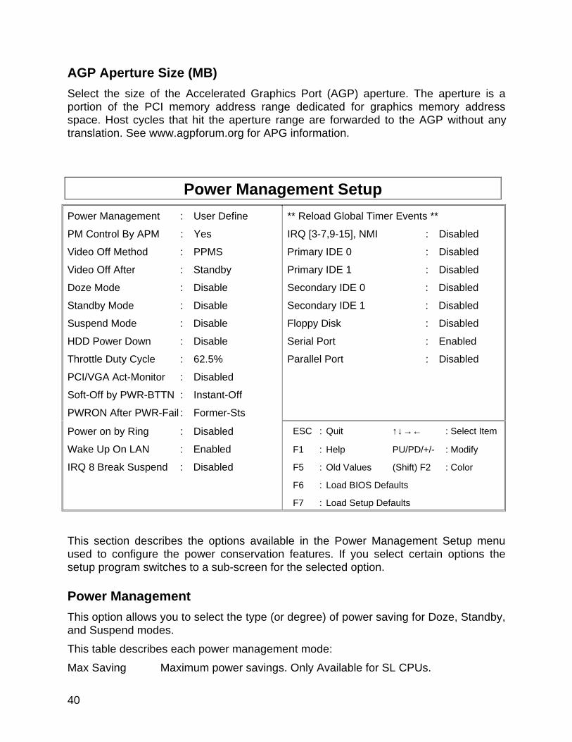
Power Management Setup
Power Management : User Define
PM Control By APM : Yes
Video Off Method : PPMS
Video Off After : Standby
Doze Mode : Disable
Standby Mode : Disable
Suspend Mode : Disable
HDD Power Down : Disable
Throttle Duty Cycle : 62.5%
PCI/VGA Act-Monitor : Disabled
Soft-Off by PWR-BTTN : Instant-Off
PWRON After PWR-Fail : Former-Sts
** Reload Global Timer Events **
IRQ [3-7,9-15], NMI : Disabled
Primary IDE 0 : Disabled
Primary IDE 1 : Disabled
Secondary IDE 0 : Disabled
Secondary IDE 1 : Disabled
Floppy Disk : Disabled
Serial Port : Enabled
Parallel Port : Disabled
Power on by Ring : Disabled
Wake Up On LAN : Enabled
IRQ 8 Break Suspend : Disabled
ESC : Quit ↑↓→← : Select Item
F1 : Help PU/PD/+/- : Modify
F5 : Old Values (Shift) F2 : Color
F6 : Load BIOS Defaults
F7 : Load Setup Defaults
This section describes the options available in the Power Management Setup menuused to configure the power conservation features. If you select certain options thesetup program switches to a sub-screen for the selected option.
Power Management
This option allows you to select the type (or degree) of power saving for Doze, Standby,and Suspend modes.
This table describes each power management mode:
Max Saving Maximum power savings. Only Available for SL CPUs.
41
User Define Set each mode individually.
Min Saving Minimum power savings.
PM Control by APM
If Advanced Power Management (APM) is installed on your system, selecting Yes givesbetter power savings.
Video Off Method
Determines the manner in which the monitor is blanked.
V/H SYNC+Blank System turns off vertical and horizontal synchronization portsand writes blanks to the video buffer.
DPMS Support Select this option if your monitor supports the Display PowerManagement Signaling (DPMS) standard of the VideoElectronics Standards Association (VESA). Use the softwaresupplied for your video subsystem to select video powermanagement values.
Blank Screen System only writes blanks to the video buffer.
Video Off After
As the system moves from lesser to greater power-saving modes, select the mode inwhich you want the monitor to blank.
Doze Mode
After the selected period of system inactivity, the CPU clock runs at slower speed whileall other devices still operate at full speed.
Standby Mode
After the selected period of system inactivity, the CPU clock stops, the hard drive entersan idle state, and the L2 cache enters a power-save mode. All other devices stilloperate at full speed.
Standby Mode
After the selected period of system inactivity, the fixed disk drive and the video shut offwhile all other devices still operate at full speed.
Suspend Mode
After the selected period of system inactivity, all devices except the CPU shut off.

42
HDD Power Down
After the selected period of drive inactivity, the hard disk drive powers down while allother devices remain active.
Throttle Duty Cycle
When the system enters Doze mode, the CPU clock runs only part of the time. You mayselect the percent of time that the clock runs.
PCI/VGA Active Monitor
When Enabled, any video activity restarts the global timer for Standby mode.
Soft-Off by PWR-BTTN
When Enabled, turning the system off with the on/off button places the system in a verylow-power-usage state, with only enough circuitry receiving power to detect powerbutton activity or Resume by Ring activity.
Power on by Ring
An input signal on the serial Ring Indicator (RI) line (in other words, an incoming call onthe modem) awakens the system from a soft off state.
Wake Up On Ring
When enabled, an input signal from a local area network (LAN) awakens the systemfrom a soft off state.
IRQ8 Break Suspend
You can Enable or Disable monitoring of IRQ8 (the Real Time Clock) so it does notawaken the system from Suspend mode.
43
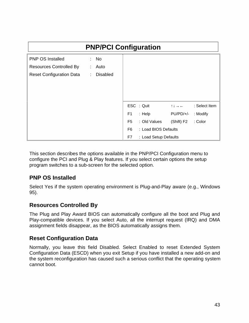
PNP/PCI Configuration
PNP OS Installed : No
Resources Controlled By : Auto
Reset Configuration Data : Disabled
ESC : Quit ↑↓→← : Select Item
F1 : Help PU/PD/+/- : Modify
F5 : Old Values (Shift) F2 : Color
F6 : Load BIOS Defaults
F7 : Load Setup Defaults
This section describes the options available in the PNP/PCI Configuration menu toconfigure the PCI and Plug & Play features. If you select certain options the setupprogram switches to a sub-screen for the selected option.
PNP OS Installed
Select Yes if the system operating environment is Plug-and-Play aware (e.g., Windows95).
Resources Controlled By
The Plug and Play Award BIOS can automatically configure all the boot and Plug andPlay-compatible devices. If you select Auto, all the interrupt request (IRQ) and DMAassignment fields disappear, as the BIOS automatically assigns them.
Reset Configuration Data
Normally, you leave this field Disabled. Select Enabled to reset Extended SystemConfiguration Data (ESCD) when you exit Setup if you have installed a new add-on andthe system reconfiguration has caused such a serious conflict that the operating systemcannot boot.
44
Integrated Peripherals
IDE HDD Block Mode : Enabled
IDE Primary Master PIO : Auto
IDE Primary Slave PIO : Auto
IDE Secondary Master PIO : Auto
IDE Secondary Slave PIO : Auto
IDE Primary Master UDMA : Auto
IDE Primary Slave UDMA : Auto
IDE Secondary Master UDMA : Auto
IDE Secondary Slave UDMA : Auto
On-Chip Primary PCI IDE : Enabled
On-Chip Secondary PCI IDE : Enabled
USB Keyboard Support : Disabled
Init Display First : AGP
Onboard Serial Port 1 : 3F8/IR4
Onboard Serial Port 2 : 2F8/IR3
UR2 Mode : Standard
Onboard Parallel Port : 378/IRQ7
Parallel Port Mode : SPP
Onboard Sound Chip : Enabled
Onboard LAN Chip : Enabled
PS/2 Mouse Control : Enabled
Onboard FDC Controller : Enabled ESC : Quit ↑↓→← : Select Item
F1 : Help PU/PD/+/- : Modify
F5 : Old Values (Shift) F2 : Color
F6 : Load BIOS Defaults
F7 : Load Setup Defaults
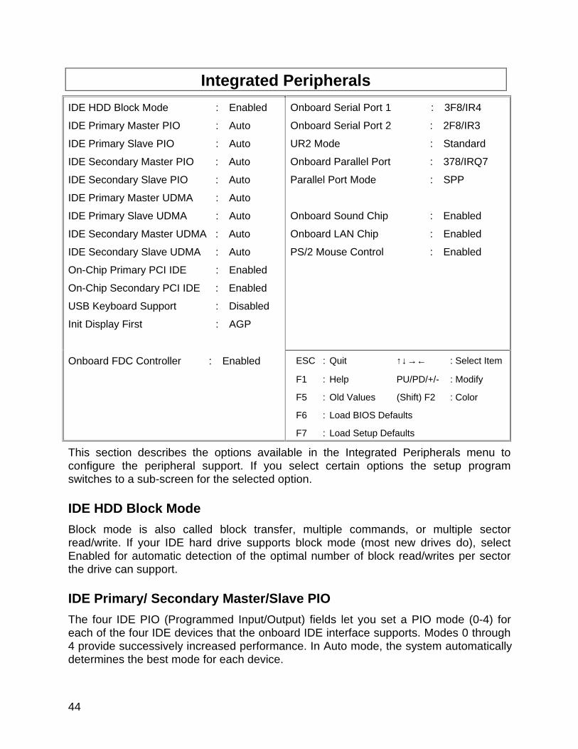
This section describes the options available in the Integrated Peripherals menu toconfigure the peripheral support. If you select certain options the setup programswitches to a sub-screen for the selected option.
IDE HDD Block Mode
Block mode is also called block transfer, multiple commands, or multiple sectorread/write. If your IDE hard drive supports block mode (most new drives do), selectEnabled for automatic detection of the optimal number of block read/writes per sectorthe drive can support.
IDE Primary/ Secondary Master/Slave PIO
The four IDE PIO (Programmed Input/Output) fields let you set a PIO mode (0-4) foreach of the four IDE devices that the onboard IDE interface supports. Modes 0 through4 provide successively increased performance. In Auto mode, the system automaticallydetermines the best mode for each device.
45
IDE Primary/ Secondary Master/Slave UDMA
UDMA (Ultra DMA) is a DMA data transfer protocol that utilizes ATA commands and theATA bus to allow DMA commands to transfer data at a maximum burst rate of 33 MB/s.When you select Auto in the four IDE UDMA fields (for each of up to four IDE devicesthat the internal PCI IDE interface supports), the system automatically determines theoptimal data transfer rate for each IDE device.
On-Chip Primary/ Secondary PCI IDE
The integrated peripheral controller contains an IDE interface with support for two IDEchannels. Select Enabled to activate each channel separately.
USB Keyboard Support
Select Enabled if your system contains a Universal Serial Bus (USB) controller and youhave a USB keyboard.
Init Display First
Initialize the AGP video display before initializing any other display device on thesystem. Thus the AGP display becomes the primary display.
Onboard FDC Controller
Select Enabled if your system has a floppy disk controller (FDC) installed on the systemboard and you wish to use it. If you install an add-in FDC or the system has no floppydrive, select Disabled in this field.
Onboard Serial Ports (1/2, A/B)
Select a logical COM port name and matching address for the first and second serialports. Select an address and corresponding interrupt for the first and second serialports.
46
Load BIOS Defaults
BIOS defaults are factory settings for the most stable, minimal performance systemoperations.
Load Setup Defaults
Setup defaults are factory settings for optimal performance system operations.
Auto-Detect Hard Disks
This “Auto-Detect Hard Disks” option detects the parameters of IDE hard disk drives,and automatically enters them into the standard CMOS setup screen.
Supervisor Password and User Password settings
Change, set, or disable a password. In BIOS versions that allow separate user andsupervisor passwords, only the supervisor password permits access to Setup. The userpassword generally allows only power-on access.
IDE HDD Auto Detection
Automatically detect and configure IDE hard disk parameters.
Save and Exit Setup
Save settings in non-volatile CMOS RAM and exit Setup.
Exit Without Saving
Abandon all changes and exit Setup.
47
Upgrading the BIOSThe system BIOS resides on a flash component. You can upgrade a flash BIOSthrough software, without taking the system apart or replacing the flash component.This appendix tells how to upgrade your system BIOS from a diskette particular for yourmotherboard. Your service representative can provide you with the latest BIOS upgradefor your system.
WARNING
Upgrading with a BIOS other than the one provided by Seanix will automaticallyvoid the product warranty. Upgrading with the incorrect BIOS might causepermanent unrecoverable damage to the motherboard.
Flashing the BIOS1. Insert the BIOS diskette into your floppy drive. At A:\, type
“awdflash <BIOS filename>” and hit <enter>
2. A Flash EPROM Programming Utility screen pops up. Press “Y” to continue.
WARNING
System must NOT be turned off during the programming operation. The systemwill re-boot if programming is successfully completed.
3. Please wait for the programming operation to complete. Once completed, take theBIOS diskette out from the floppy drive and press any key to restart the computer.
4. Once the system has re-booted, go into the CMOS Setup main. Select “Load SetupDefaults”. You can change this CMOS setting at a later time if you want tocustomize your settings.
5. Save and exit the BIOS Setup Program.
48
4.Error and Information Messages
During the power-on self test (POST), the BIOS either sounds a beep code or displaysa message when it detects a correctable error.
Following is a list of POST messages for the ISA BIOS kernel. Specific chipset portsand BIOS extensions may include additional messages. An error message may befollowed by a prompt to press F1 to continue or press DEL to enter Setup.
BeepCurrently the only beep code indicates that a video error has occurred and the BIOScannot initialize the video screen to display any additional information. This beep codeconsists of a single long beep followed by two short beeps. Any other beeps areprobably a RAM problem.
BIOS ROM checksum error - System haltedThe checksum of the BIOS code in the BIOS chip is incorrect, indicating the BIOS codemay have become corrupt. Contact your system dealer to replace the BIOS.
CMOS battery failedCMOS battery is no longer functional. Contact your system dealer for a replacementbattery.
CMOS checksum error - Defaults loadedChecksum of CMOS is incorrect, so the system loads the default equipmentconfiguration. A checksum error may indicate that CMOS has become corrupt. Thiserror may have been caused by a weak battery. Check the battery and replace ifnecessary.
CPU at nnnnDisplays the running speed of the CPU.
Display switch is set incorrectly.The display switch on the motherboard can be set to either monochrome or color. Thismessage indicates the switch is set to a different setting than indicated in Setup.Determine which setting is correct, and then either turn off the system and change thejumper, or enter Setup and change the VIDEO selection.
Press ESC to skip memory testThe user may press Esc to skip the full memory test.

49
Floppy disk(s) failCannot find or initialize the floppy drive controller or the drive. Make sure the controlleris installed correctly. If no floppy drives are installed, be sure the Diskette Driveselection in Setup is set to NONE or AUTO.
Hard Disk initializing, Please wait a moment...Some hard drives require extra time to initialize.
Hard Disk Install FailureCannot find or initialize the hard drive controller or the drive. Make sure the controlleris installed correctly. If no hard drives are installed, be sure the Hard Drive selection inSetup is set to NONE.
Hard disk(s) diagnosis failThe system may run specific disk diagnostic routines. This message appears if one ormore hard disks return an error when the diagnostics run.
Keyboard error or no keyboard presentCannot initialize the keyboard. Make sure the keyboard is attached correctly and nokeys are pressed during POST. To purposely configure the system without akeyboard, set the error halt condition in Setup to HALT ON ALL, BUT KEYBOARD.The BIOS then ignores the missing keyboard during POST.
Keyboard is locked out - Unlock the keyThis message usually indicates that one or more keys have been pressed during thekeyboard tests. Be sure no objects are resting on the keyboard.
Memory Test:This message displays during a full memory test, counting doom the memory areasbeing tested.
Memory test failIf POST detects an error during memory testing, additional information appears givingspecifics about the type and location of the memory error.
Override enabled - Defaults loadedIf the system cannot boot using the current CMOS configuration, the BIOS canoverride the current configuration with a set of BIOS defaults designed for the moststable, minimal-performance system operations.
Press TAB to show POST screenSystem OEMs may replace the Phoenix Technologies Award BIOS POST display withtheir own proprietary display. Including this message in the OEM display permits theoperator to switch between the OEM display and the default POST display.

50
Primary master hard disk failPOST detects an error in the primary master IDE hard drive.
Primary slave hard disk failPOST detects an error in the secondary master IDE hard drive.
Resuming from disk, Press TAB to show POST screenPhoenix Technologies offers a save-to-disk feature for notebook computers. Thismessage may appear when the operator re-starts the system after a save-to-diskshutdown. See the Press TAB ... message above for a description of this feature.
Secondary master hard disk failPOST detects an error in the primary slave IDE hard drive.
Secondary slave hard disk failPOST detects an error in the secondary slave IDE hard drive.
51
5.GlossaryADDRESS:
A specific location in the memory of the computer where information about programs,data and software drivers is stored. Peripheral devices such as mouse, modems, etc.require a specific I/0 port address and interrupt in order to function properly.
BIOS: (BASIC INPUT OUTPUT SYSTEM)
That part of a ROM that is the interface between the system hardware and theoperating system. The ROM BIOS is a group of low level programs responsible forinterfacing the computer to peripheral devices, such as disk drives, serial and parallelports, keyboard, and video display. Low-level BIOS routines are common to alloperating systems and are generally resident in ROM. High-level BIOS routines arespecific to the particular operating system in use and are therefore generally stored ondisk, and loaded only when the operating system is booted.
BIT:
A binary digit that is the most reducible element of computer information. Eight bitsmake one byte.
BOOT or BOOTSTRAP:
A small ROM-based program which is automatically loaded when the system is firstpowered up (or "booted), in order to load and execute an operating system or otherlarge program from disk. Also, the process of starting the computer, either by turning onthe power, pressing the Reset switch or by pressing the CTRL + ALT + DEL keyssimultaneously. The latter is known as a "warm boot".
BYTE:
Smallest unit of storage required to hold a character of information in memory or on adisk.
BUS CLOCK:
The speed at which data is transferred between the microprocessor and the I/Ochannel.
CMOS:
Acronym for Complementary Metal Oxide Semiconductor. CMOS integrated circuitryuses very little electrical power. Hence CMOS RAM is ideal for storing systemconfiguration information that cannot be stored permanently in ROM.
COM PORT:
Communication port where devices such as a mouse or an external modem areattached.
52
CONFIG.SYS:
A file usually located in the root directory of the boot disk that contains informationrequired to load installable device drivers and other system configuration parameters.
CONVENTIONAL MEMORY:
System main memory from 0 to 640KB. Many programs run in this area.
COPROCESSOR:
An auxiliary processor that reduces microprocessor overhead and increases systemspeed by executing certain math related functions. System with a Pentium processor,the math coprocessor is built into the microprocessor.
CPU: (CENTRAL PROCESSING UNIT)
Also called the microprocessor. The “brain" of the computer, where programinstructions and arithmetic operations are executed.
CPU CLOCK:
The speed at which the microprocessor executes its instructions.
DOS: (DISK OPERATING SYSTEM)
Software that controls the activities performed by the computer. DOS sets up anenvironment under which application software can load and function. It is an interfacebetween the system and application software.
DRAM: (DYNAMIC RANDOM ACCESS MEMORY)
A type of RAM that requires a refresh cycle to keep information valid. Main systemmemory uses DRAM.
EXPANSION SLOT:
A connector on the system board into which an adapter card can be inserted.
EXTENDED MEMORY:
Memory beyond the 1 MBYTES limit that is accessed by programs such as Windows.
HERTZ:
A unit of frequency which is equivalent to one cycle per second.
INTERFACE:
The connection between the system board and a peripheral.
INTERLEAVING:
A technique for improving system performance by speeding up memory access.Successive memory locations are assigned to different memory banks. Then, when thesystem requires the information, it accesses both banks simultaneously rather thanhaving to access a single bank sequentially.
53
INTERRUPT:
Special operation used by hardware peripheral devices to allow them to communicatewith the Central Processing Unit. Each peripheral device is allocated a unique interruptnumber which the CPU recognizes when talking to the device.
ISA:
Industry Standard Architecture.
JUMPER:
A patch cable, wire or other such device used to establish a circuit.
MEMORY:
RAM and ROM are devices used to hold information and programs while they arebeing accessed by the system.
MICROPROCESSOR:
Also known as the CPU. The "brain" of the system, which contains the circuitry usedfor calculation and communication with the rest of the system.
PAGE MODE:
Special function in DRAM that saves cycle time by not re-loading the “Row Addressstrobe bits”.
PARALLEL PORT:
Also called "printer port", or LPT 1:, the parallel port is used to attach a printer or otherperipheral using a Centronics† parallel cable.
PARITY BIT:
An additional non-informational bit appended to a group of 8 bits to make the numberof ones in the group of bits either even or odd. This is an elementary error correctionmechanism. Example: During a subsequent read from a memory location, and usingodd parity, the system will check the sum of ones. If the sum of ones is NOT still oddthen the system knows that the information at that location has been corrupted.
SERIAL PORT:
Communication port used by the computer to communicate with the outside world. AnIBM PC compatible normally recognizes four standard serial ports: COM1, COM2,COM3 and COM4 which are used to attach a mouse, modems, serial printers, plottersand other serial devices
SHADOW RAM:
Refers to the technique of copying BIOS routines from slower ROM chips to fasterRAM, thereby increasing system performance
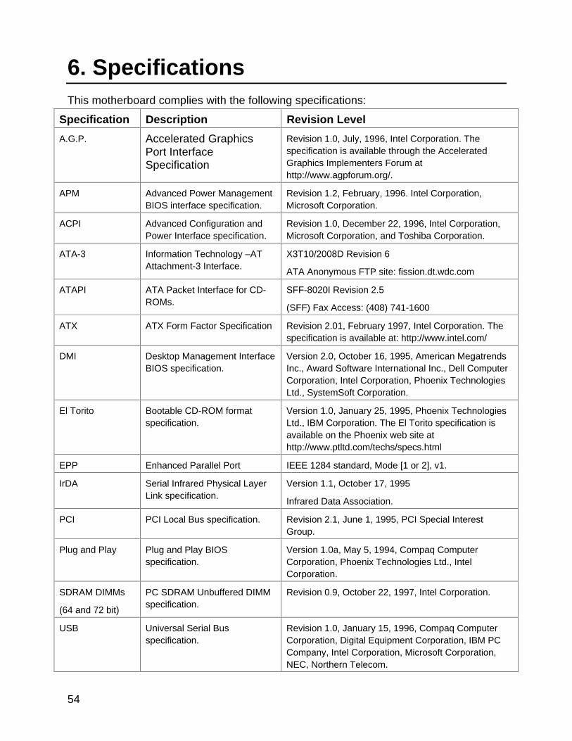
54
6. SpecificationsThis motherboard complies with the following specifications:
Specification Description Revision Level
A.G.P. Accelerated GraphicsPort InterfaceSpecification
Revision 1.0, July, 1996, Intel Corporation. Thespecification is available through the AcceleratedGraphics Implementers Forum athttp://www.agpforum.org/.
APM Advanced Power ManagementBIOS interface specification.
Revision 1.2, February, 1996. Intel Corporation,Microsoft Corporation.
ACPI Advanced Configuration andPower Interface specification.
Revision 1.0, December 22, 1996, Intel Corporation,Microsoft Corporation, and Toshiba Corporation.
ATA-3 Information Technology –ATAttachment-3 Interface.
X3T10/2008D Revision 6
ATA Anonymous FTP site: fission.dt.wdc.com
ATAPI ATA Packet Interface for CD-ROMs.
SFF-8020I Revision 2.5
(SFF) Fax Access: (408) 741-1600
ATX ATX Form Factor Specification Revision 2.01, February 1997, Intel Corporation. Thespecification is available at: http://www.intel.com/
DMI Desktop Management InterfaceBIOS specification.
Version 2.0, October 16, 1995, American MegatrendsInc., Award Software International Inc., Dell ComputerCorporation, Intel Corporation, Phoenix TechnologiesLtd., SystemSoft Corporation.
El Torito Bootable CD-ROM formatspecification.
Version 1.0, January 25, 1995, Phoenix TechnologiesLtd., IBM Corporation. The El Torito specification isavailable on the Phoenix web site athttp://www.ptltd.com/techs/specs.html
EPP Enhanced Parallel Port IEEE 1284 standard, Mode [1 or 2], v1.
IrDA Serial Infrared Physical LayerLink specification.
Version 1.1, October 17, 1995
Infrared Data Association.
PCI PCI Local Bus specification. Revision 2.1, June 1, 1995, PCI Special InterestGroup.
Plug and Play Plug and Play BIOSspecification.
Version 1.0a, May 5, 1994, Compaq ComputerCorporation, Phoenix Technologies Ltd., IntelCorporation.
SDRAM DIMMs
(64 and 72 bit)
PC SDRAM Unbuffered DIMMspecification.
Revision 0.9, October 22, 1997, Intel Corporation.
USB Universal Serial Busspecification.
Revision 1.0, January 15, 1996, Compaq ComputerCorporation, Digital Equipment Corporation, IBM PCCompany, Intel Corporation, Microsoft Corporation,NEC, Northern Telecom.