Embed Size (px)
Citation preview
WS-415-55 / 11.10.97
GAS STOVEGAS STOVEGAS STOVEGAS STOVEGAS STOVEINSTINSTINSTINSTINSTALLAALLAALLAALLAALLATION AND OPERATION AND OPERATION AND OPERATION AND OPERATION AND OPERATION INSTRUCTIONS FORTION INSTRUCTIONS FORTION INSTRUCTIONS FORTION INSTRUCTIONS FORTION INSTRUCTIONS FOR
GAS-FIRED STOVEGAS-FIRED STOVEGAS-FIRED STOVEGAS-FIRED STOVEGAS-FIRED STOVE
NATURAL GAS MODEL GS3500 - NGS3500 - NGS3500 - NGS3500 - NGS3500 - NPROPANE GAS MODEL GS3500 - PGS3500 - PGS3500 - PGS3500 - PGS3500 - P
CERTIFIED FOR CANADA AND UNITED STATES USING ANSI / AGA / CGA METHODS
INSTINSTINSTINSTINSTALLER: THESE INSTRUCTIONS MUST BE CONVEYED TO AND REMAIN WITH THE HOMEOWNER.ALLER: THESE INSTRUCTIONS MUST BE CONVEYED TO AND REMAIN WITH THE HOMEOWNER.ALLER: THESE INSTRUCTIONS MUST BE CONVEYED TO AND REMAIN WITH THE HOMEOWNER.ALLER: THESE INSTRUCTIONS MUST BE CONVEYED TO AND REMAIN WITH THE HOMEOWNER.ALLER: THESE INSTRUCTIONS MUST BE CONVEYED TO AND REMAIN WITH THE HOMEOWNER.CERTIFIED UNDER CANADIAN AND AMERICAN NATIONAL STANDARDS,
CAN 1-2.1-M86, AND ANSI Z21.50-1996 RESPECTIVELY FOR GAS-FIRED VENTED ROOM HEATER AND VENTED DECORATIVE GAS APPLIANCE
WWWWWARNING:ARNING:ARNING:ARNING:ARNING: Improper installation, adjustment, alteration, service or maintenance cancause injury or property damage. Refer to this manual. For assistance or additionalinformation consult a qualified installer, service agency or the gas supplier.
FOR YOUR SAFETYFOR YOUR SAFETYFOR YOUR SAFETYFOR YOUR SAFETYFOR YOUR SAFETYDo not store or use gasoline or other flammable vapours and liquids in the vicinity of
this or any other appliance.
WHAWHAWHAWHAWHATTTTT T T T T TO DO IF YOU SMELLO DO IF YOU SMELLO DO IF YOU SMELLO DO IF YOU SMELLO DO IF YOU SMELL GAS: GAS: GAS: GAS: GAS:• Turn off main gas supply.• Open windows.• Do not try to light any appliance.• Do not touch any electrical switch; Do not use
any phone in your building.
• Extinguish any open flame.• Immediately call your gas supplier from a
neighbour's phone. Follow the gas supplier'sinstructions.
• If you cannot reach your gas supplier, call thefire department.
Fax: (705)722-6031 Email: [email protected]: WWW.NAPOLEON.ON.CA
Wolf Steel Ltd., RR#1, 9 NAPOLEON RD.,Barrie, ON., Canada L4M 4Y8 (705)721-1212
R-2000WORLD RECOGNITION FOR QUALITY
ISO 9002 CERTIFIED
Registered QualitySystem RRRR

2
WS-415-55 / 11.10.97
PLEASE RETAIN THIS MANUAL FOR FUTURE REFERENCE
TTTTTABLE ABLE ABLE ABLE ABLE ofofofofof CONTENTS CONTENTS CONTENTS CONTENTS CONTENTS
PGPGPGPGPG 2-42-42-42-42-4 INTRODUCTIONINTRODUCTIONINTRODUCTIONINTRODUCTIONINTRODUCTIONWarrantyGeneral InstructionsGeneral InformationCare of Glass, Enamelled & Plated Parts
5-65-65-65-65-6 VENTINGVENTINGVENTINGVENTINGVENTINGLocationChimney InstallationInstalling "B" VentAdding Vent SectionsFlashing & Storm Collar InstallationCombustion Air
66666 GAS INSTGAS INSTGAS INSTGAS INSTGAS INSTALLAALLAALLAALLAALLATIONTIONTIONTIONTION77777 OPTIONAL BLOWER INSTOPTIONAL BLOWER INSTOPTIONAL BLOWER INSTOPTIONAL BLOWER INSTOPTIONAL BLOWER INSTALLAALLAALLAALLAALLATIONTIONTIONTIONTION
PGPGPGPGPG 88888 FINISHINGFINISHINGFINISHINGFINISHINGFINISHINGOrnamental TrivetLog Placement / Charcoal Embers
9-109-109-109-109-10 OPERAOPERAOPERAOPERAOPERATION / MAINTENANCETION / MAINTENANCETION / MAINTENANCETION / MAINTENANCETION / MAINTENANCESpill SwitchVenting Action CheckOperating InstructionsMaintenance
1111111111 ADJUSTMENTSADJUSTMENTSADJUSTMENTSADJUSTMENTSADJUSTMENTSPilot Burner AdjustmentVenturi Adjustment
11-1211-1211-1211-1211-12 REPLACEMENTSREPLACEMENTSREPLACEMENTSREPLACEMENTSREPLACEMENTSOrdering Replacement PartsReplacement PartsAccessories
13-1413-1413-1413-1413-14 TROUBLE SHOOTING GUIDETROUBLE SHOOTING GUIDETROUBLE SHOOTING GUIDETROUBLE SHOOTING GUIDETROUBLE SHOOTING GUIDE
WARNINGWARNINGWARNINGWARNINGWARNING• Do not burn wood or other materials in this stove.• Adults and especially children should be alerted to the hazards of high surface temperatures and should stay away to
avoid burns or clothing ignition. Supervise young children when they are in the same room as the stove.• Due to high temperatures, the stove should be located out of traffic and away from furniture and draperies.• Clothing or other flammable material should not be placed on or near the stove.• Any safety screen or guard removed for servicing must be replaced prior to operating the stove.• It is imperative that the control compartments, burners and circulating blower and its passageway in the stove and venting
system are kept clean. The stove and its venting system should be inspected before use and at least annually by a qualifiedservice person. More frequent cleaning may be required due to excessive lint from carpeting, bedding material, etc. Thestove area must be kept clear and free from combustible materials, gasoline and other flammable vapours and liquids.
• Under no circumstances should this stove be modified.• This stove must not be connected to a chimney flue pipe serving a separate solid fuel burning appliance.• Do not use this stove if any part has been under water. Immediately call a qualified service technician to inspect the stove
and to replace any part of the control system and any gas control which has been under water.• Do not operate the stove with the glass door removed, cracked or broken. Replacement of the glass should be done by a
licensed or qualified service person.• Do not strike or slam shut the stove glass door.
PURGE ALL GAS LINES WITH THE GLASS DOOR OF THE STOVE REMOVED. ASSURE THAPURGE ALL GAS LINES WITH THE GLASS DOOR OF THE STOVE REMOVED. ASSURE THAPURGE ALL GAS LINES WITH THE GLASS DOOR OF THE STOVE REMOVED. ASSURE THAPURGE ALL GAS LINES WITH THE GLASS DOOR OF THE STOVE REMOVED. ASSURE THAPURGE ALL GAS LINES WITH THE GLASS DOOR OF THE STOVE REMOVED. ASSURE THAT A CONTINUOUS GAS FLOW IS AT A CONTINUOUS GAS FLOW IS AT A CONTINUOUS GAS FLOW IS AT A CONTINUOUS GAS FLOW IS AT A CONTINUOUS GAS FLOW IS ATTTTTTHE BURNER BEFORE INSTTHE BURNER BEFORE INSTTHE BURNER BEFORE INSTTHE BURNER BEFORE INSTTHE BURNER BEFORE INSTALLING THE DOOR.ALLING THE DOOR.ALLING THE DOOR.ALLING THE DOOR.ALLING THE DOOR.
UNDER EXTREME VENT CONFIGURAUNDER EXTREME VENT CONFIGURAUNDER EXTREME VENT CONFIGURAUNDER EXTREME VENT CONFIGURAUNDER EXTREME VENT CONFIGURATIONS, ALLOW SEVERAL MINUTES (5-15) FOR THE FLAME TO STTIONS, ALLOW SEVERAL MINUTES (5-15) FOR THE FLAME TO STTIONS, ALLOW SEVERAL MINUTES (5-15) FOR THE FLAME TO STTIONS, ALLOW SEVERAL MINUTES (5-15) FOR THE FLAME TO STTIONS, ALLOW SEVERAL MINUTES (5-15) FOR THE FLAME TO STABILIZE AFTER IGNITION.ABILIZE AFTER IGNITION.ABILIZE AFTER IGNITION.ABILIZE AFTER IGNITION.ABILIZE AFTER IGNITION.

3
WS-415-55 / 11.10.97
NAPOLEON gas fireplaces are manufactured under the strict Standard of the world recognizedISO9002 Quality Assurance Certificate.
NAPOLEON products are designed with superior components and materials, assembled by trained craftsmen whotake great pride in their work. The burner and valve assembly are leak and test-fired at a quality test station. Thecomplete fireplace is thoroughly inspected by a qualified technician before packaging to ensure that you, the cus-tomer, receives the quality product that you expect from NAPOLEON.
NAPOLEON GAS FIREPLACE PRESIDENT'S LIFETIME LIMITED WARRANTYNAPOLEON GAS FIREPLACE PRESIDENT'S LIFETIME LIMITED WARRANTYNAPOLEON GAS FIREPLACE PRESIDENT'S LIFETIME LIMITED WARRANTYNAPOLEON GAS FIREPLACE PRESIDENT'S LIFETIME LIMITED WARRANTYNAPOLEON GAS FIREPLACE PRESIDENT'S LIFETIME LIMITED WARRANTY
The following materials and workmanship in your new The following materials and workmanship in your new The following materials and workmanship in your new The following materials and workmanship in your new The following materials and workmanship in your new NAPOLEONNAPOLEONNAPOLEONNAPOLEONNAPOLEON gas fireplace are war- gas fireplace are war- gas fireplace are war- gas fireplace are war- gas fireplace are war-ranted against defects for as long as you own the fireplace. This covers: combustion chamber,ranted against defects for as long as you own the fireplace. This covers: combustion chamber,ranted against defects for as long as you own the fireplace. This covers: combustion chamber,ranted against defects for as long as you own the fireplace. This covers: combustion chamber,ranted against defects for as long as you own the fireplace. This covers: combustion chamber,heat exchanger, stainless steel burner, phazer™ logs and embers, ceramic glass (thermal break-heat exchanger, stainless steel burner, phazer™ logs and embers, ceramic glass (thermal break-heat exchanger, stainless steel burner, phazer™ logs and embers, ceramic glass (thermal break-heat exchanger, stainless steel burner, phazer™ logs and embers, ceramic glass (thermal break-heat exchanger, stainless steel burner, phazer™ logs and embers, ceramic glass (thermal break-age only), gold plated parts against tarnishing, porcelainized enamelled components and alumi-age only), gold plated parts against tarnishing, porcelainized enamelled components and alumi-age only), gold plated parts against tarnishing, porcelainized enamelled components and alumi-age only), gold plated parts against tarnishing, porcelainized enamelled components and alumi-age only), gold plated parts against tarnishing, porcelainized enamelled components and alumi-num extrusion trims.num extrusion trims.num extrusion trims.num extrusion trims.num extrusion trims.
Electrical (110V and millivolt) components and wearable parts such as blowers, gas valves,Electrical (110V and millivolt) components and wearable parts such as blowers, gas valves,Electrical (110V and millivolt) components and wearable parts such as blowers, gas valves,Electrical (110V and millivolt) components and wearable parts such as blowers, gas valves,Electrical (110V and millivolt) components and wearable parts such as blowers, gas valves,thermal switch, switches, wiring, remote controls, ignitor, gasketing, and pilot assembly arethermal switch, switches, wiring, remote controls, ignitor, gasketing, and pilot assembly arethermal switch, switches, wiring, remote controls, ignitor, gasketing, and pilot assembly arethermal switch, switches, wiring, remote controls, ignitor, gasketing, and pilot assembly arethermal switch, switches, wiring, remote controls, ignitor, gasketing, and pilot assembly arecovered and covered and covered and covered and covered and NAPOLEONNAPOLEONNAPOLEONNAPOLEONNAPOLEON will provide replacement parts free of charge during the first yearwill provide replacement parts free of charge during the first yearwill provide replacement parts free of charge during the first yearwill provide replacement parts free of charge during the first yearwill provide replacement parts free of charge during the first yearof the limited warranty.of the limited warranty.of the limited warranty.of the limited warranty.of the limited warranty.
Labour related to warranty repair is covered free of charge during the first year. RepairLabour related to warranty repair is covered free of charge during the first year. RepairLabour related to warranty repair is covered free of charge during the first year. RepairLabour related to warranty repair is covered free of charge during the first year. RepairLabour related to warranty repair is covered free of charge during the first year. Repairwork, however, requires the prior approval of an authorized company official. Labour costs towork, however, requires the prior approval of an authorized company official. Labour costs towork, however, requires the prior approval of an authorized company official. Labour costs towork, however, requires the prior approval of an authorized company official. Labour costs towork, however, requires the prior approval of an authorized company official. Labour costs tothe account of the account of the account of the account of the account of NAPOLEONNAPOLEONNAPOLEONNAPOLEONNAPOLEON are based on a predetermined rate schedule and any repair work are based on a predetermined rate schedule and any repair work are based on a predetermined rate schedule and any repair work are based on a predetermined rate schedule and any repair work are based on a predetermined rate schedule and any repair workmust be done through an authorized must be done through an authorized must be done through an authorized must be done through an authorized must be done through an authorized NAPOLEONNAPOLEONNAPOLEONNAPOLEONNAPOLEON dealer. dealer. dealer. dealer. dealer.
CONDITIONS AND LIMITCONDITIONS AND LIMITCONDITIONS AND LIMITCONDITIONS AND LIMITCONDITIONS AND LIMITAAAAATIONSTIONSTIONSTIONSTIONSNAPOLEON warrants its products against manufacturing defects to the original purchaser only -- i.e., the individual or legal entity (registered customer) whose name appears on the
warranty registration card filed with NAPOLEON -- provided that the purchase was made through an authorized NAPOLEON dealer and is subject to the following conditions andlimitations:
This factory warranty is nontransferable and may not be extended whatsoever by any of our representatives.The gas fireplace must be installed by a licenced, authorized service technician or contractor. Installation must be done in accordance with the installation instructions included with
the product and all local and national building and fire codes.This limited warranty does not cover damages caused by misuse, lack of maintenance, accident, alterations, abuse or neglect and parts installed from other manufacturers will nullify
this warranty.This limited warranty further does not cover any scratches, dents, corrosion or discolouring caused by excessive heat, abrasive and chemical cleaners nor chipping on porcelain enamel
parts, mechanical breakage of PHAZER™ logs and embers, nor any venting components used in the installation of the fireplace.NAPOLEON warrants its stainless steel burners against defects in workmanship and material for life, subject to the following conditions: During the first 10 years NAPOLEON will
replace or repair the defective parts at our option free of charge. From 10 years to life, NAPOLEON will provide replacement burners at 50% of the current retail price.In the first year only, this warranty extends to the repair or replacement of warranted parts which are defective in material or workmanship provided that the product has been operated
in accordance with the operation instructions and under normal conditions.After the first year, with respect to this President's Limited Lifetime Warranty, NAPOLEON may, at its discretion, fully discharge all obligations with respect to this warranty by refunding
to the original warranted purchaser the wholesale price of any warranted but defective part(s).After the first year, NAPOLEON will not be responsible for installation, labour or any other costs or expenses related to the reinstallation of a warranted part, and such expenses are
not covered by this warranty.Notwithstanding any provisions contained in this President's Limited Lifetime Warranty, NAPOLEON’S responsibility under this warranty is defined as above and it shall not in any
event extend to any incidental, consequential or indirect damages.This warranty defines the obligations and liability of NAPOLEON with respect to the NAPOLEON gas fireplace and any other warranties expressed or implied with respect to this
product, its components or accessories are excluded.NAPOLEON neither assumes, nor authorizes any third party to assume, on its behalf, any other liabilities with respect to the sale of this product. NAPOLEON will not be responsible
for: over-firing, downdrafts, spillage caused by environmental conditions such as rooftops, buildings, nearby trees, hills, mountains, inadequate vents or ventilation, excessive ventingconfigurations, insufficient makeup air, or negative air pressures which may or may not be caused by mechanical systems such as exhaust fans, furnaces, clothes dryers, etc.
Any damages to fireplace, combustion chamber, heat exchanger, brass trim or other component due to water, weather damage, long periods of dampness, condensation, damagingchemicals or cleaners will not be the responsibility of NAPOLEON.
The bill of sale or copy will be required together with a serial number and a model number when making any warranty claims from your authorized dealer. The warranty registrationcard must be returned within fourteen days to register the warranty.
NAPOLEON reserves the right to have its representative inspect any product or part thereof prior to honouring any warranty claim.
All specifications and designs are subject to change without prior notice due to on-going product improvements. Napoleon® is a registered trademark of wolf steel ltd. Patentsu.s. 5.303.693.801 - can. 2.073.411, 2.082.915. © wolf steel ltd.
4
WS-415-55 / 11.10.97
GENERAL INSTRUCTIONSGENERAL INSTRUCTIONSGENERAL INSTRUCTIONSGENERAL INSTRUCTIONSGENERAL INSTRUCTIONSTHIS GAS STOVE SHOULD BE INSTALLED AND SERVICED BY A QUALIFIED INSTALLER to conform with local codes.In absence of local codes, install to the current CAN1-B149 Installation Code in Canada or to the National Fuel Gas Code, ANSIZ223.1-1988, and NFPA 54-1988 in the United States.The stove and its individual shutoff valve must be disconnected from the gas supply piping system during any pressure testingof that system at test pressures in excess of 1/2 psig (3.5 kPa). The stove must be isolated from the gas supply piping systemby closing its individual manual shutoff valve during any pressure testing of the gas supply piping system at test pressuresequal to or less than 1/2 psig (3.5 kPa).A 1/8 inch NPT plug, accessible for test gauge connection, must be installed immediately upstream of the gas supply connec-tion to the stove.This stove must be connected to either a 4" 'B' vent system or any accepted lined chimney system using a liner and ventconnector listed to ULC-S635M (in Canada) or UL-1777 (in USA). The venting connection must be in compliance with the ventmanufacturers installation instructions.The stove, when installed with a blower, must be electrically connected and grounded in accordance with local codes. In theabsence of local codes, use the current CSA C22.1 CANADIAN ELECTRICAL CODE in Canada or the ANSI/NFPA 70-1990NATIONAL ELECTRICAL CODE in the United States. The blower power cord must be connected into a properly groundedreceptacle. The grounding prong must not be removed from the cord plug.Provide adequate ventilation and combustion air. Provide adequate accessibility clearance for servicing and operating thestove. Never obstruct the front opening of the stove.
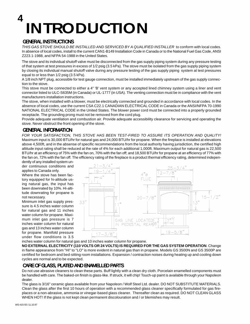
GENERAL INFORMAGENERAL INFORMAGENERAL INFORMAGENERAL INFORMAGENERAL INFORMATIONTIONTIONTIONTIONFOR YOUR SATISFACTION, THIS STOVE HAS BEEN TEST-FIRED TO ASSURE ITS OPERATION AND QUALITY!Maximum input is 30,000 BTU/hr for natural gas and 24,000 BTU/hr for propane. When the fireplace is installed at elevationsabove 4,500ft, and in the absense of specific recommendations from the local authority having jurisdiction, the certified highaltitude input rating shall be reduced at the rate of 4% for each additional 1,000ft. Maximum output for natural gas is 22,500BTU/hr at an efficiency of 75% with the fan on, 70% with the fan off; and 18,500 BTU/hr for propane at an efficiency of 77% withthe fan on, 72% with the fan off. The efficiency rating of the fireplace is a product thermal efficiency rating, determined indepen-dently of any installed system un-der continuous conditions andapplies to Canada only.Where the stove has been fac-tory equipped for hi-altitude us-ing natural gas, the input hasbeen downrated by 10%. Hi-alti-tude downrating for propane isnot necessary.Minimum inlet gas supply pres-sure is 4.5 inches water columnfor natural gas and 11 incheswater column for propane. Maxi-mum inlet gas pressure is 7inches water column for naturalgas and 13 inches water columnfor propane. Manifold pressureunder flow conditions is 3.5inches water column for natural gas and 10 inches water column for propane.NO EXTERNAL ELECTRICITY (110 VOLTS OR 24 VOLTS) IS REQUIRED FOR THE GAS SYSTEM OPERATION. Changein flame appearance from "HI" to "LO" is more evident in natural gas than in propane. Models GS 3500N and GS 3500P arecertified for bedroom and bed-sitting room installations. Expansion / contraction noises during heating up and cooling downcycles are normal and to be expected.
CARE OF GLASS, PLACARE OF GLASS, PLACARE OF GLASS, PLACARE OF GLASS, PLACARE OF GLASS, PLATED AND ENAMELLED PTED AND ENAMELLED PTED AND ENAMELLED PTED AND ENAMELLED PTED AND ENAMELLED PARARARARARTSTSTSTSTSDo not use abrasive cleaners to clean these parts. Buff lightly with a clean dry cloth. Porcelain enamelled components mustbe handled with care. The baked-on finish is glass-like. If struck, it will chip! Touch-up paint is available through your Napoleondealer.The glass is 3/16" ceramic glass available from your Napoleon / Wolf Steel Ltd. dealer. DO NOT SUBSTITUTE MATERIALS.Clean the glass after the first 10 hours of operation with a recommended glass cleaner specifically formulated for gas fire-places or a non-abrasive, ammonia or vinegar-based glass cleaner. Thereafter clean as required. DO NOT CLEAN GLASSWHEN HOT! If the glass is not kept clean permanent discolouration and / or blemishes may result.
INTRODUCTION

5
WS-415-55 / 11.10.97
CHIMNEY INSTCHIMNEY INSTCHIMNEY INSTCHIMNEY INSTCHIMNEY INSTALLAALLAALLAALLAALLATION TION TION TION TION THREE TYPES OF CHIMNEY SYSTEMS MAY BE USED WITH THIS STOVE:
INSTALLING 'B' VENT:1.Move the stove into position. Try to center the exhaust of the stove,
midway between two joist to prevent having to cut them. Use a plumbbob to line up the center.
2. Cut and frame an opening in the roof to provide a 1"clearance between the outside of the 'B' vent andany combustible material. DO NOT FILL THISSPACE WITH ANY TYPE OF MATERIAL. Nail head-ers between the joist for extra support. Firestop spac-ers must be placed on the bottom of each framedopening in any floor or on top of any framed openingin any attic that the 'B' vent passes through. FIG-URE 2.
3. Hold a plumb bob from the underside of the roof todetermine where the opening in the roof should be.Cut and frame the roof opening to maintain proper 1"clearances. FIGURE 3
For aesthetics, a 6" telescoping stove pipe may beinstalled over the 4" vent connection or 'B' vent. Either use a Napoleon stove pipe adapter available from your Napoleon dealeror cut approximately 2" from the crimped end of the 6" diameter chimney section to be inserted into the 6-1/4" canopy opening.
minimum 18" from stove top to ceiling
NO ADDITIONAL FLOOR PROTECTION IS REQUIRED.NO ADDITIONAL FLOOR PROTECTION IS REQUIRED.NO ADDITIONAL FLOOR PROTECTION IS REQUIRED.NO ADDITIONAL FLOOR PROTECTION IS REQUIRED.NO ADDITIONAL FLOOR PROTECTION IS REQUIRED.
A. 8"B. 5"C. 1"D. 1" 'B' vent or 6" singlewall vent connectorE. 7"F. 11"
VENTINGLOCALOCALOCALOCALOCATIONTIONTIONTIONTIONThe most desirable and benefical location for a Napoleon Stove is in the centre of a building, thereby allowing the most efficientuse of the heat created. The location of windows, doors and the traffic flow in the room where the stove is to be located shouldbe considered. If possible, you should choose a location where the chimney will pass through the house without cutting a flooror roof joist.MAINTAIN THESE MINIMUM CLEARANCES TO COMBUSTIBLES:
A CHIMNEY VENTING THIS STOVE SHALL NOT VENT ANY SOLID FUEL BURNING APPLIANCE.
ALL HORIZONTALL HORIZONTALL HORIZONTALL HORIZONTALL HORIZONTAL RUNS MUST HAAL RUNS MUST HAAL RUNS MUST HAAL RUNS MUST HAAL RUNS MUST HAVE A 1/4 INCH RISE PER FOOTVE A 1/4 INCH RISE PER FOOTVE A 1/4 INCH RISE PER FOOTVE A 1/4 INCH RISE PER FOOTVE A 1/4 INCH RISE PER FOOT.....
FIGURE 1
FIGURE 2
FIGURE 3

6
WS-415-55 / 11.10.97
GAS INSTALLATIONBring the gas line to the stove through either a hole in the pedestal back or in thefloor area directly beneath the pedestal base. Install rigid black pipe, a flex connec-tor if local codes permit, or 1/2" type L copper tubing with a 3/8" to 1/2" adapter anda shut-off valve to the stove. FIGURE 7. Seal and tighten securely. The adapter willbe required between the gas valve and the copper tubing or flex connector.
DO NOT KINK CONNECTOR. Check for gas leaks by brushing on a soap and water solution. DO NOT USE OPENFLAME.Alternate locations for the on-off switch are shown in FIGURE 8. For ease of accessibility, an optional remote wall switch ormillivolt thermostat may be installed in a convenient location. Route single strand millivolt wire through the electrical holelocated at the left rear side of the pedestal. The recommended maximum lead length depends on the wire size:
WIRE SIZE MAX. LENGTH14gauge 100 feet16gauge 60 feet18gauge 40 feet
Attach the two leads to terminals 1 and 3 located on the gas valve
OT PIL
LO
IHT P
I
L
O
N O
FF O
FIGURE 7
DO NOT CONNECT EITHER THE WDO NOT CONNECT EITHER THE WDO NOT CONNECT EITHER THE WDO NOT CONNECT EITHER THE WDO NOT CONNECT EITHER THE WALL SWITCH, THER-ALL SWITCH, THER-ALL SWITCH, THER-ALL SWITCH, THER-ALL SWITCH, THER-MOSTMOSTMOSTMOSTMOSTAAAAAT OR GAS VT OR GAS VT OR GAS VT OR GAS VT OR GAS VALALALALALVE TO ELECTRICITY (110 VOLVE TO ELECTRICITY (110 VOLVE TO ELECTRICITY (110 VOLVE TO ELECTRICITY (110 VOLVE TO ELECTRICITY (110 VOLTS)TS)TS)TS)TS)
FIGURE 8
ADDING VENT SECTIONS:Add vent sections, twist locking (clockwise) securely, to the required height. The vent should extend, at least, 3 feet above itspoint of contact with the roof and, at least, 2 feet higher than any wall, roof or building within 10 feet. FIGURE 4. (This is a guide
line only; local venting codes should be followed which may differ in height and clearancerequirements.)
INSTINSTINSTINSTINSTALLING FLASHING AND STORM COLLARALLING FLASHING AND STORM COLLARALLING FLASHING AND STORM COLLARALLING FLASHING AND STORM COLLARALLING FLASHING AND STORM COLLARRemove nails from the shingles above and to the sides of the chimney. Place the flashing
over the vent pipe and slide it underneath the sidesand upper edge of the shingles. Ensure that the ventpipe is properly centered within the flashing, giving a3/4" margin all around. Fasten to the roof on the topand sides. DO NOT NAIL through the lower portionof the flashing. Make weather-tight by sealing withcaulking. Where possible, cover the sides and topedges of the flashing with roofing material.Apply waterproof caulking around the vent, 1" abovethe top of the flashing and push the storm collar downinto the caulking. FIGURE 5. Attach a rain cap to thetop of the last vent section.
COMBUSTION AIR COMBUSTION AIR COMBUSTION AIR COMBUSTION AIR COMBUSTION AIRANY STOVE NEEDS AIR FOR SAFE OPERATION AND MUST BE INSTALLED INSUCH A WAY THAT ADEQUATE COMBUSTION AIR IS AVAILABLE. THIS UNIT ISDESIGNED TO FUNCTION USING EITHER OUTSIDE OR INSIDE (ROOM) AIR.If using outside air, connections can be made either through a hole in the wall to line up with the holein the pedestal back or through a hole in the floor to line up with the hole in the pedestal base. Usea fresh air kit available through your Napoleon Firplace dealer or Wolf Steel Ltd. Secure the 4"diameter aluminium liner in either the back or base of the pedestal. If the air intake is through thefloor, the hole in the pedestal back should be covered. Avoid cutting away floor joist, electrical wiringor plumbing. Seal around the outside pipe with insulation to prevent drafts. FIGURE 6.
FIGURE 5FIGURE 4
FIGURE 6

7
WS-415-55 / 11.10.97
OPTIONAL BLOWER SYSTEMINSTALLATION TO BE DONE BY A QUALIFIED INSTALLER and must be electrically connected and grounded in accor-dance with local codes. In the absence of local codes, use the current CSA C22.1 CANADIAN ELECTRICAL CODE in Canada orthe ANSI/NFPA 70-1990 NATIONAL ELECTRICAL CODE in the United States.
1. Turn off the gas supply to the fireplace, ifnecessary. Mount the variable speed switch: in-sert the rheostat stem through the 3/8" diameterhole in the pedestal and from the front securewith the pal nut. Add the knob.
2. Reaching in from the back of the unit, locatethe bracket holding the heat sensor as shown tothe weld stud and secure using one of the #6nuts.
3. Attach the bare end of wire (A) to the blackwire of the speed switch using a nut connector.Attach the flag connector at the other end to oneof the prongs of the heat sensor.
4. Insert the universal bushing into the 7/8" di-ameter hole in the back of the pedestal.
5. Thread the leads of the power cord throughthe slot located at the bottom left of the stoveback panel. Attach the terminal of the ground wire(green) to the threaded weld stud and securewith a nut.
6. Connect one bare lead of wire (B) to the white wire of the speed switchusing a nut connector. Connect the other end to the bare lead wire of the blowercord using a nut connector.
7. Attach the other terminal ofthe wire (already attached to theblower) to the heat sensor. Oneend must be pushed through thebushing in order to connect to theblower prong.
8. Mount the cord terminal tothe other blower prong.
9. Using the holes shown, at-tach the blower to the back stove panel.
10. Bring out any slack in the blower cord. Place the cord into the splitstrain relief bushing, just at the point where the cord enters the slot. Clamp the two pieces together and insert the bushingsecurely into the slot.
Leak test using a soap and water solution, if the gas supply was disconnected at the valve. Because the blower is thermallyactivated, when turned on, it will automatically start approximately 15-30 minutes after lighting the fireplace and will run forapproximately 30-45 minutes after the fireplace has been turned off. Use of the fan increases the output of heat.
FIGURE 9
FIGURE 10
white
grou
ndbla
ck
FIGURE 11

8
WS-415-55 / 11.10.97
FINISHING
ORNAMENTORNAMENTORNAMENTORNAMENTORNAMENTAL TRIVETAL TRIVETAL TRIVETAL TRIVETAL TRIVETInsert the trivet into the space on the stove top. FIGURE 12
LOG PLACEMENT INSTRUCTIONS / CHARCOAL EMBERSLOG PLACEMENT INSTRUCTIONS / CHARCOAL EMBERSLOG PLACEMENT INSTRUCTIONS / CHARCOAL EMBERSLOG PLACEMENT INSTRUCTIONS / CHARCOAL EMBERSLOG PLACEMENT INSTRUCTIONS / CHARCOAL EMBERSPHAZERTM logs and charcoal embers, exclusive to Napoleon Fireplaces, provide a unique and realistic glowing effect that isdifferent in every installation. Take the time to carefully position the charcoal embers for a maximum glowing effect.
1. Place the front log onto the main burner, placing it 1/4" - 3/8" away from the burner ports to avoid blocking/covering them.The left and right spacing between the log ends and the burner ports should be equal. Press down onto the skewering screws.YOU MAY FIND IT EASIER TO PLACE SOME CHARCOAL EMBERS BENEATH THE FRONT LOG NOW.
2. Place the back log onto the log support brackets located on the rear wall of the combustion chamber. The notch situatedat the lower left of the back log should be centered evenly above the pilot assembly. FIGURE 13.
3. While supporting the back log, to prevent it from falling forward, set the three smaller logs into the pockets and groovesof the front and back logs, respectively.Log colours may vary. During the initial use of the fireplace, the colours will become more uniform as colour pigments burn induring the heat activated curing process.
CHARCOAL EMBERS: Randomly place the embers beneath the front log,covering all of the burner area beneath the hollowed out section of thelog. FIGURE 14. Place the remaining embers along the front. Keepember dust away from burner ports to avoid plugging them.Fine dust found in bottom of bag not to be used. PHAZERTM logsand charcoal embers glow when exposed to direct flame. Use onlycertified PHAZERTM logs and charcoal embers available from yourNapoleon / Wolf Steel Ltd. dealer.
FIGURE 12
BACK LOG
CENTERLOG
CHARCOAL EMBERS
LEFTLOG
FRONT LOG
LOGRIGHT
SCREWSKEWERING
POSITIONING THELOGS IMPROP-
ERLY WILL CAUSEFLAME IMPINGE-
MENT ANDCARBONING.
FIGURE 13
FIGURE 14
9
WS-415-55 / 11.10.97
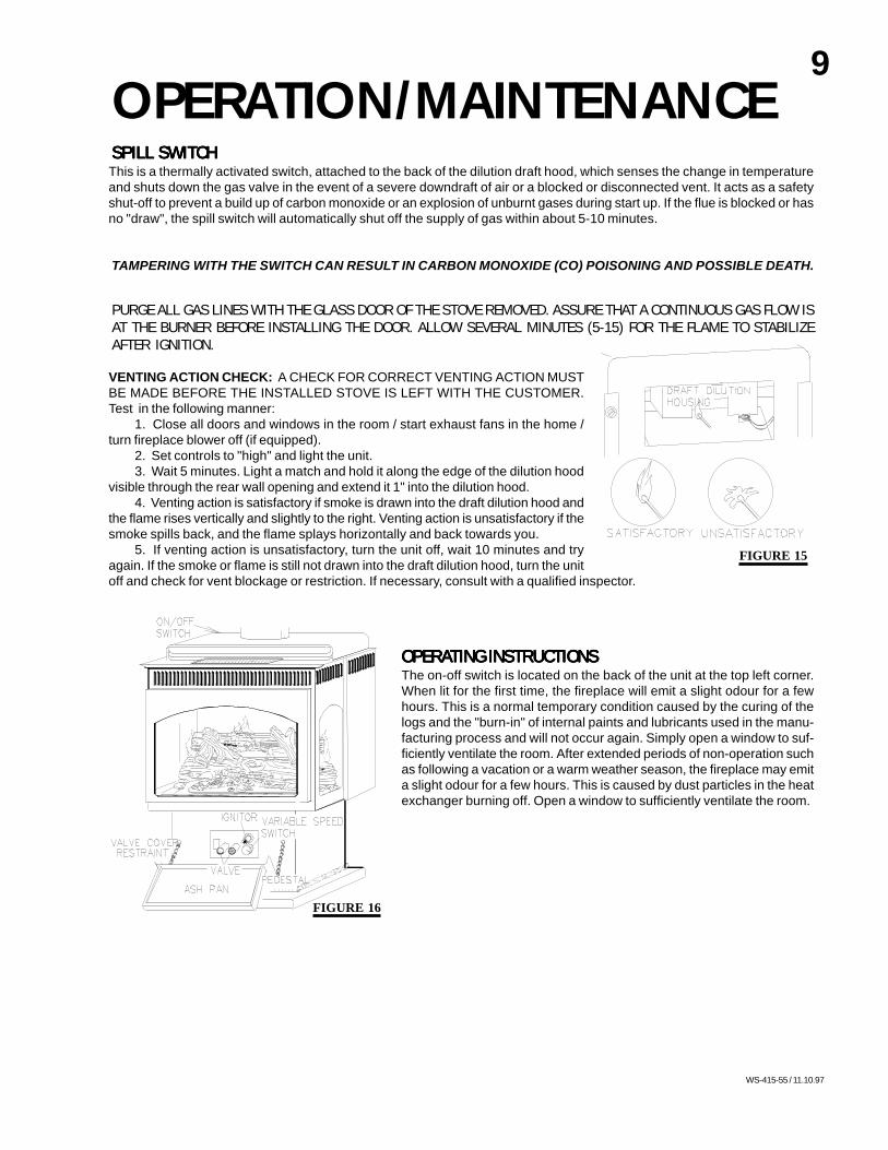
OPERATION/MAINTENANCESPILL SWITCHSPILL SWITCHSPILL SWITCHSPILL SWITCHSPILL SWITCHThis is a thermally activated switch, attached to the back of the dilution draft hood, which senses the change in temperatureand shuts down the gas valve in the event of a severe downdraft of air or a blocked or disconnected vent. It acts as a safetyshut-off to prevent a build up of carbon monoxide or an explosion of unburnt gases during start up. If the flue is blocked or hasno "draw", the spill switch will automatically shut off the supply of gas within about 5-10 minutes.
TAMPERING WITH THE SWITCH CAN RESULT IN CARBON MONOXIDE (CO) POISONING AND POSSIBLE DEATH.
PURGE ALL GAS LINES WITH THE GLASS DOOR OF THE STOVE REMOVED. ASSURE THAT A CONTINUOUS GAS FLOW ISAT THE BURNER BEFORE INSTALLING THE DOOR. ALLOW SEVERAL MINUTES (5-15) FOR THE FLAME TO STABILIZEAFTER IGNITION.
VENTING ACTION CHECK: A CHECK FOR CORRECT VENTING ACTION MUSTBE MADE BEFORE THE INSTALLED STOVE IS LEFT WITH THE CUSTOMER.Test in the following manner:
1. Close all doors and windows in the room / start exhaust fans in the home /turn fireplace blower off (if equipped).
2. Set controls to "high" and light the unit.3. Wait 5 minutes. Light a match and hold it along the edge of the dilution hood
visible through the rear wall opening and extend it 1" into the dilution hood.4. Venting action is satisfactory if smoke is drawn into the draft dilution hood and
the flame rises vertically and slightly to the right. Venting action is unsatisfactory if thesmoke spills back, and the flame splays horizontally and back towards you.
5. If venting action is unsatisfactory, turn the unit off, wait 10 minutes and tryagain. If the smoke or flame is still not drawn into the draft dilution hood, turn the unitoff and check for vent blockage or restriction. If necessary, consult with a qualified inspector.
OPERAOPERAOPERAOPERAOPERATING INSTRUCTIONSTING INSTRUCTIONSTING INSTRUCTIONSTING INSTRUCTIONSTING INSTRUCTIONSThe on-off switch is located on the back of the unit at the top left corner.When lit for the first time, the fireplace will emit a slight odour for a fewhours. This is a normal temporary condition caused by the curing of thelogs and the "burn-in" of internal paints and lubricants used in the manu-facturing process and will not occur again. Simply open a window to suf-ficiently ventilate the room. After extended periods of non-operation suchas following a vacation or a warm weather season, the fireplace may emita slight odour for a few hours. This is caused by dust particles in the heatexchanger burning off. Open a window to sufficiently ventilate the room.
IH
LO
L
F
T
IO
O
P
O
F
N
FIGURE 16
FIGURE 15
10
WS-415-55 / 11.10.97
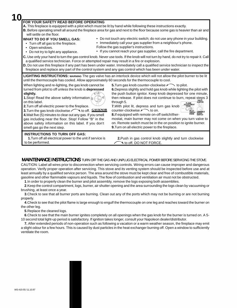
A. This fireplace is equipped with a pilot which must be lit by hand while following these instructions exactly.B. Before operating smell all around the fireplace area for gas and next to the floor because some gas is heavier than air and
will settle on the floor.WHAT TO DO IF YOU SMELL GAS:
• Turn off all gas to the fireplace.• Open windows.• Do not try to light any appliance.
C. Use only your hand to turn the gas control knob. Never use tools. If the knob will not turn by hand, do not try to repair it. Calla qualified service technician. Force or attempted repair may result in a fire or explosion.
D. Do not use this fireplace if any part has been under water. Immediately call a qualified service technician to inspect thefireplace and replace any part of the control system and any gas control which has been under water.
• Do not touch any electric switch; do not use any phone in your building.• Immediately call your gas supplier from a neighbour's phone.Follow the gas supplier's instructions.• If you cannot reach your gas supplier, call the fire department.
LIGHTING INSTRUCTIONS: WARNING The gas valve has an interlock device which will not allow the pilot burner to be lituntil the thermocouple has cooled. Allow approximately 60 seconds for the thermocouple to cool.When lighting and re-lighting, the gas knob cannot beturned from pilot to off unless the knob is depressedslightly.1.Stop! Read the above safety informationon this label.2.Turn off all electric power to the fireplace.3.Turn the gas knob clockwise to off.4.Wait five (5) minutes to clear out any gas. If you smellgas including near the floor. Stop! Follow "B" in theabove safety information on this label. If you don'tsmell gas go the next step.
GAS KNOB
FOR YOUR SAFETY READ BEFORE OPERATING
P
I
NO
L
O
TFFO
5.Turn gas knob counter-clockwise to pilot.6.Depress slightly and hold gas knob while lighting the pilot withthe push button ignitor. Keep knob depressed for one minute,then release. If pilot does not continue to burn, repeat steps 3through 5.7.With pilot lit, depress and turn gas knobcounter-clockwise to on.8.If equipped with remote on-off switch/ther-mostat, main burner may not come on when you turn valve toon. Remote switch must be in the on position to ignite burner.9.Turn on all electric power to the fireplace.
LO
FLAMEKNOB
ADJUSTMENTI H
VARIABLESPEEDSWITCH
LP
O F F N
T
I O
O
PILOTKNOBON/OFF
IGNITORPIEZO
INSTRUCTIONS TO TURN OFF GAS:1.Turn off all electrical power to the unit if service is
to be performed.2.Push in gas control knob slightly and turn clockwise
to off. DO NOT FORCE.
MAINTENANCE INSTRUCTIONS MAINTENANCE INSTRUCTIONS MAINTENANCE INSTRUCTIONS MAINTENANCE INSTRUCTIONS MAINTENANCE INSTRUCTIONS TURN OFF THE GAS AND UNPLUG ELECTRICAL POWER BEFORE SERVICING THE STOVE.CAUTION: Label all wires prior to disconnection when servicing controls. Wiring errors can cause improper and dangerousoperation. Verify proper operation after servicing. This stove and its venting system should be inspected before use and atleast annually by a qualified service person. The area around the stove must be kept clear and free of combustible materials,gasoline and other flammable vapours and liquids. The flow of combustion and ventilation air must not be obstructed.
1.In order to properly clean the burner and pilot assembly, remove the logs exposing both assemblies.2.Keep the control compartment, logs, burner, air shutter opening and the area surrounding the logs clean by vacuuming or
brushing, at least once a year.3.Check to see that all burner ports are burning. Clean out any of the ports which may not be burning or are not burning
properly.4.Check to see that the pilot flame is large enough to engulf the thermocouple on one leg and reaches toward the burner on
the other leg.5.Replace the cleaned logs.6.Check to see that the main burner ignites completely on all openings when the gas knob for the burner is turned on. A 5-
10 second total light-up period is satisfactory. If ignition takes longer, consult your Napoleon dealer/distributor.7. After extended periods of non-operation such as following a vacation or a warm weather season, the fireplace may emit
a slight odour for a few hours. This is caused by dust particles in the heat exchanger burning off. Open a window to sufficientlyventilate the room.
11
WS-415-55 / 11.10.97
REPLACEMENT PREPLACEMENT PREPLACEMENT PREPLACEMENT PREPLACEMENT PARARARARARTS, GS 3500TS, GS 3500TS, GS 3500TS, GS 3500TS, GS 3500PPPPPARARARARART #T #T #T #T #
GA-GI-135.07GA-GI-135.17GA-GI-135.06GA-GI-135.15GA-GI-135.09GA-GI-135.16GL-611GL-610WS-385-33WS-300-22WS-300-21GA-GDS-562.014GA-GDS-562.015GA-GS-010.441GA-GS-010.442GA-GDS-280.20GA-GDS-280.21GS-325PBEP-230KGA-GI-550.01EP-715.73
DESCRIPTIONDESCRIPTIONDESCRIPTIONDESCRIPTIONDESCRIPTIONBURNER ASSEMBLYS.I.T. VALVE - NGS.I.T. VALVE - LPPIEZO IGNITORPILOT ASSEMBLY - NGPILOT ASSEMBLY - LP#51 PILOT ORIFICE - NG#30 PILOT ORIFICE - LPBURNER ORIFICE - #36 NGBURNER ORIFICE - #54 LPBURNER ORIFICE - #37 HI ALT NGBURNER ORIFICE - #55 HI ALT LPSPILL SWITCH - NGSPILL SWITCH - LPTHERMOCOUPLETHERMOPILEFLAME ADJUSTMENT KNOB EXTENSIONPILOT ON/OFF KNOB EXTENSIONBURNER ON/OFF SWITCHCANOPY LOUVRE SET - POLISHED BRASS
PPPPPARARARARART #T #T #T #T #GA-GS-010.399WS-725-25WS-725-26WS-357-01WS-100-38WS-100-39WS-455-23WS-455-24WS-455-04WS-455-03WS-455-13WS-455-02WS-660-07WS-660-06WS-680-05WS-680-04WS-380-006WS-380-007WS-660-09CL29PB
DESCRIPTIONDESCRIPTIONDESCRIPTIONDESCRIPTIONDESCRIPTIONBACK LOGFRONT LOG (PROPANE GAS ONLY)FRONT LOG (NATURAL GAS ONLY)RIGHT LOGCENTER LOGLEFT LOGLOG SET ASSEMBLYc/w CHARCOAL EMBERSPROPANE GAS ONLY
LOG SET ASSEMBLYc/wCHARCOAL EMBERSNATURAL GAS ONLY
NAPOLEON LOGOFRONT DOOR GLASSSIDE WINDOW GLASSFRONT GLASS GASKETSIDE GLASS GASKETFRONT GLASS & GASKETSIDE GLASS & GASKETFRONT DOOR FRAMESIDE GLASS FRAMEPOLISHED BRASS FACIABLACK TRIVETCHARCOAL EMBERSASH FENDER TRIM C/W CORNER BRACKET
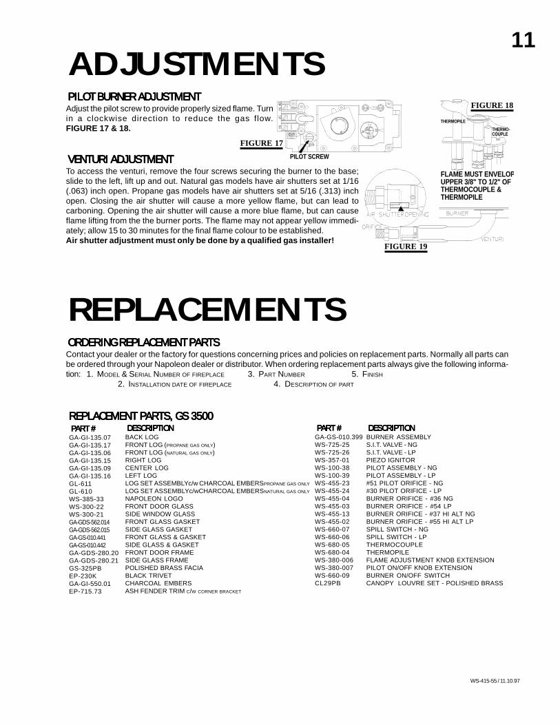
ADJUSTMENTSPILOT BURNER ADJUSTMENTPILOT BURNER ADJUSTMENTPILOT BURNER ADJUSTMENTPILOT BURNER ADJUSTMENTPILOT BURNER ADJUSTMENTAdjust the pilot screw to provide properly sized flame. Turnin a clockwise direction to reduce the gas flow.FIGURE 17 & 18.
VENTURI ADJUSTMENTVENTURI ADJUSTMENTVENTURI ADJUSTMENTVENTURI ADJUSTMENTVENTURI ADJUSTMENTTo access the venturi, remove the four screws securing the burner to the base;slide to the left, lift up and out. Natural gas models have air shutters set at 1/16(.063) inch open. Propane gas models have air shutters set at 5/16 (.313) inchopen. Closing the air shutter will cause a more yellow flame, but can lead tocarboning. Opening the air shutter will cause a more blue flame, but can causeflame lifting from the the burner ports. The flame may not appear yellow immedi-ately; allow 15 to 30 minutes for the final flame colour to be established.Air shutter adjustment must only be done by a qualified gas installer!
REPLACEMENTSORDERING REPLACEMENT PORDERING REPLACEMENT PORDERING REPLACEMENT PORDERING REPLACEMENT PORDERING REPLACEMENT PARARARARARTSTSTSTSTSContact your dealer or the factory for questions concerning prices and policies on replacement parts. Normally all parts canbe ordered through your Napoleon dealer or distributor. When ordering replacement parts always give the following informa-tion: 1. MODEL & SERIAL NUMBER OF FIREPLACE 3. PART NUMBER 5. FINISH
2. INSTALLATION DATE OF FIREPLACE 4. DESCRIPTION OF PART
P
I
PI
PILOT SCREW
LOT
N O
L
O
T
HI
LO
FF O
FLAME MUST ENVELOPUPPER 3/8" TO 1/2" OFTHERMOCOUPLE & THERMOPILE
THERMO-COUPLE
THERMOPILE
FIGURE 17
FIGURE 18
FIGURE 19
12
WS-415-55 / 11.10.97
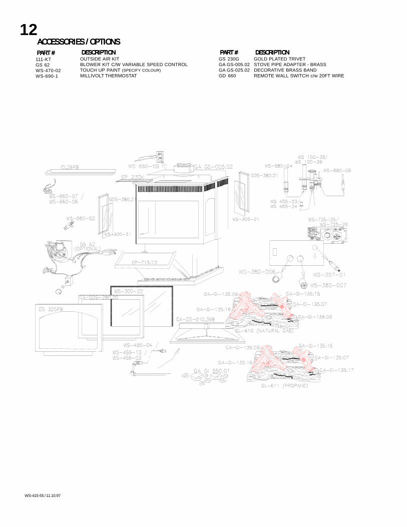
ACCESSORIES / OPTIONSACCESSORIES / OPTIONSACCESSORIES / OPTIONSACCESSORIES / OPTIONSACCESSORIES / OPTIONSPPPPPARARARARART #T #T #T #T #
111-KTGS 62WS-470-02WS-690-1
DESCRIPTIONDESCRIPTIONDESCRIPTIONDESCRIPTIONDESCRIPTIONGOLD PLATED TRIVETSTOVE PIPE ADAPTER - BRASSDECORATIVE BRASS BANDREMOTE WALL SWITCH c/w 20FT WIRE
DESCRIPTIONDESCRIPTIONDESCRIPTIONDESCRIPTIONDESCRIPTIONOUTSIDE AIR KITBLOWER KIT C/W VARIABLE SPEED CONTROLTOUCH UP PAINT (SPECIFY COLOUR)MILLIVOLT THERMOSTAT
PPPPPARARARARART #T #T #T #T #GS 230GGA GS-005.02GA GS-025.02GD 660
I HLO
L
FF
N
T
IO
O
P
O

13
WS-415-55 / 11.10.97
TROUBLE SHOOTING GUIDE
White / grey film forms. Sulphur from fuel is beingdeposited on glass, logs orcombustion chamber sur-faces.
- clean the glass with a recommended gas glass cleaner or anon-abrasive ammonia or vinegar based glass cleaner. DO NOTCLEAN GLASS WHEN HOT. If deposits are not cleaned off regu-larly, the glass may become permanently marked.
SYMPTOMSYMPTOMSYMPTOMSYMPTOMSYMPTOM PROBLEMPROBLEMPROBLEMPROBLEMPROBLEM TEST SOLUTIONTEST SOLUTIONTEST SOLUTIONTEST SOLUTIONTEST SOLUTION
BEFORE ATTEMPTING TO TROUBLESHOOT, PURGE YOUR UNIT AND INITIALLY LIGHT THE PILOT AND THE MAIN BURNER WITH THE GLASS DOOR REMOVED.
Exhaust fumes smelledin room, headaches.
Fireplace is spilling. - check all seals. Check venting action. Consult with a qualifiedinspector.
Pilot will not light.
Out of propane gas - fill the tank.
- check if pilot can be lit by a match- check that the wire is connected to the push button ignitor.- check if the push button ignitor needs tightening.- replace the wire if the wire insulation is broken or frayed.- replace the electrode if the ceramic insulator is cracked or bro-ken.- replace the push button ignitor.
No spark at pilot burner
Spark gap is incorrect - spark gap should be 0.150" to 0.175" (5/32" to 11/64" approx.)from the electrode tip and the pilot burner. To ensure proper elec-trode location, tighten securing nut (finger tight plus 1/4 turn).
- check that the manual valve is turned on.- check the pilot orifice for blockage.- replace the valve.- call the gas distributor.
No gas at the pilot burner
PILOTTHERMOPILEBURNER
ELECTRODE
THERMO-COUPLE
Pilot goes out when thegas knob is released.
System is not correctlypurged.Out of propane gas.Pilot flame is not largeenoughThe gas valve has an
interlock device whichwill not allow the pilotburner to be lit until thethermocouple hascooled. Allow approxi-mately 60 seconds forthe thermocouple tocool.
- turn up the pilot flame.Pilot flame is not engulfing thethermocouple.
- loosen and tighten thermocouple.- clean thermocouple and valve connection.- replace thermocouple.- replace valve.
Thermocouple shorting.
Faultly thermocouple.
Faulty valve. - replace.
- fill the tank.
- purge the gas line.
- turn up the pilot flame.
- replace.
Carbon is being depos-ited on glass, logs orcombustion chambersurfaces. Flame is impinging on the
logs or combustion cham-ber.
- check that the logs are correctly positioned.- open air shutter to increase the primary air.- check the input rate: check the manifold pressure and orificesize as specified by the rating plate values.- check that the door gasketing is not broken or missing and thatthe seal is tight.- check that both 4" and 7" vent liners are free of holes and wellsealed at all joints.- check that minimum rise per foor has been adhered to for anyhorizontal venting.
Air shutter has becomeblocked
- ensure air shutter opening is free of lint or other obstructions.
14
WS-415-55 / 11.10.97
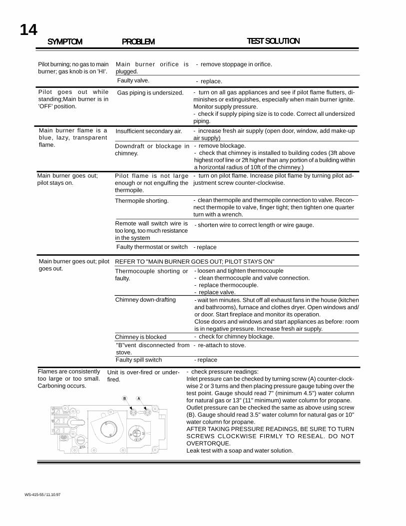
TEST SOLUTIONTEST SOLUTIONTEST SOLUTIONTEST SOLUTIONTEST SOLUTIONPROBLEMPROBLEMPROBLEMPROBLEMPROBLEMSYMPTOMSYMPTOMSYMPTOMSYMPTOMSYMPTOM
Pilot burning; no gas to mainburner; gas knob is on 'HI'.
Pilot goes out whilestanding;Main burner is in'OFF' position.
- turn on all gas appliances and see if pilot flame flutters, di-minishes or extinguishes, especially when main burner ignite.Monitor supply pressure.- check if supply piping size is to code. Correct all undersizedpiping.
Main burner flame is ablue, lazy, transparentflame.
Insufficient secondary air. - increase fresh air supply (open door, window, add make-upair supply)
Downdraft or blockage inchimney.
- remove blockage.- check that chimney is installed to building codes (3ft abovehighest roof line or 2ft higher than any portion of a building withina horizontal radius of 10ft of the chimney.)
- clean thermopile and thermopile connection to valve. Recon-nect thermopile to valve, finger tight; then tighten one quarterturn with a wrench.
Pilot flame is not largeenough or not engulfing thethermopile.
Main burner goes out;pilot stays on.
- turn on pilot flame. Increase pilot flame by turning pilot ad-justment screw counter-clockwise.
Gas piping is undersized.
Main burner orifice isplugged.
- remove stoppage in orifice.
Faulty valve. - replace.
Main burner goes out; pilotgoes out.
REFER TO "MAIN BURNER GOES OUT; PILOT STAYS ON"
Thermopile shorting.
Remote wall switch wire istoo long, too much resistancein the systemFaulty thermostat or switch
- shorten wire to correct length or wire gauge.
- replace
Thermocouple shorting orfaulty.
- loosen and tighten thermocouple- clean thermocouple and valve connection.- replace thermocouple.- replace valve.
Chimney down-drafting - wait ten minutes. Shut off all exhaust fans in the house (kitchenand bathrooms), furnace and clothes dryer. Open windows and/or door. Start fireplace and monitor its operation.Close doors and windows and start appliances as before: roomis in negative pressure. Increase fresh air supply.
Chimney is blocked - check for chimney blockage.- re-attach to stove."B"vent disconnected from
stove.Faulty spill switch - replace
Flames are consistentlytoo large or too small.Carboning occurs.
Unit is over-fired or under-fired.
- check pressure readings:Inlet pressure can be checked by turning screw (A) counter-clock-wise 2 or 3 turns and then placing pressure gauge tubing over thetest point. Gauge should read 7" (minimum 4.5") water columnfor natural gas or 13" (11" minimum) water column for propane.Outlet pressure can be checked the same as above using screw(B). Gauge should read 3.5" water column for natural gas or 10"water column for propane.AFTER TAKING PRESSURE READINGS, BE SURE TO TURNSCREWS CLOCKWISE FIRMLY TO RESEAL. DO NOTOVERTORQUE.Leak test with a soap and water solution.
P
I
AB
PILOT
N O
L
O
T
HI
LO
FF O