Embed Size (px)
Citation preview

Freestanding Gas Stove
Owners &Installation
Man
ual
LISTINGS AND CODE APPROVALS
These gas appliances have beentested in accordance with AG 103,NZS 5262 and have been certified bythe Australian Gas Association forinstallation and operation asdescribed in these Installation andOperating Instructions.
Your unit should be servicedannually by an authorised serviceperson.
918-363
Models: FG37-NGFG37-LPG
PLEASE KEEP THESE INSTRUCTIONSFOR FUTURE REFERENCE
Head Office - New Zealand1-37 Mt Wellington Hwy.Panmure,P.O. Box 14349Auckland 6.
AustraliaP.O. Box 533Braeside, Victoria, 3195
WARNING:Improper installation, adjustment,alteration, service or maintenance cancause injury or property damage. Refer tothis manual. For assistance or additionalinformation consult an authorised installer,service agency or the gas supplier.
FOR YOUR SAFETYDo not store or use gasoline or otherflammable vapours and liquids in the vicinityof this or any other appliance.
Installation and service must be performedby an authorised installer, service agency orthe gas supplier.
FOR YOUR SAFETYWhat to do if you smell gas:
Do not try to light any appli-anceDo not touch any electricalswitch: do not use anyphone in your building.Immediately call your gassupplier from a neighbour'sphone. Follow the gas sup-plier's instructions.If you cannot reach yourgas supplier, call the firedepartment.
01/06/05

2 FG37 Masport Rear Flued Room Sealed Freestanding Gas Heater
To the New Owner:
Congratulations! You are the owner of a state-of-the-art Masport Rear Flued Room Sealed Freestanding Gas Stove by FPI
Fireplace Products International. The Masport Gas Series of hand crafted appliances has been designed to provide you with
all the warmth and charm of a woodstove, at the flick of a switch. The models FG37-NG, and F37-LPG of this series has
been approved by Warnock Hersey for both safety and efficiency. As it also bears our own mark, it promises to provide you
with economy, comfort and security for many trouble free years to follow. Please take a moment now to acquaint yourself
with these instructions and the many features of your Masport Rear Flued Room Sealed Freestanding Gas Stove.

FG37 Masport Rear Flued Room Sealed Freestanding Gas Heater 3
TABLE OF CONTENTS
Page Page
Operating Instructions
Operating Instructions ............................................... 19Lighting Procedure .................................................... 19Resetting the Unit ..................................................... 19Shutdown Procedure ................................................. 19First Fire ................................................................... 19Fan Operation ........................................................... 19Adjusting Flame Heights ........................................... 19Normal Operating Sounds of Gas Appliances ............ 20Summary of Controls ................................................ 20Pilot Adjustment ....................................................... 20Copy of Lighting Plate Instructions ............................ 21
Maintenance
Maintenance Instructions .......................................... 22Gold Plated Doors ..................................................... 22Latch Adjustment ...................................................... 23Log Replacement ...................................................... 23Glass Replacement ................................................... 23Fan Maintenance ...................................................... 24Removing Valve ......................................................... 25
Parts List
Replacement Parts List ............................................. 26
Warranty
Warranty ................................................................... 31
Specifications diagram ................................................ 2Data Plate ................................................................... 4
Installation
Specifications ............................................................. 5Before You Start ......................................................... 5General Safety Information .......................................... 5Installation Checklist ................................................... 6Clearances to Combustibles ....................................... 6Locating Your MASPORT Gas Stove .......................... 6Combustion and Ventilation Air ................................... 6Exterior Flue Terminal Locations ................................. 7Fluing Installation Precautions..................................... 8Safety Precautions for the Installer .............................. 8Planning Your Fluing Installation ................................. 8Fluing Arrangements - Vertical Terminations ............... 9Flue Restrictor Position ............................................... 9Fluing: Residential and Manufactured
Homes/Mobile Homes Installation ....................... 10Horizontal Installations .............................................. 10Vertical Termination with Co-linear Flex System ....... 12Gas Connection ........................................................ 12System Data Chart - FG37 ........................................ 12Conversion from NG to LPG ...................................... 13Aeration Adjustment .................................................. 15Log Installation .......................................................... 15Door Installation ........................................................ 16Gas Pipe Pressure Testing ....................................... 17Valve Description ...................................................... 17Louvre Installation...................................................... 17Optional Remote Control Installation ......................... 18Final Check ............................................................... 18Wiring Diagram ......................................................... 18

4 FG37 Masport Rear Flued Room Sealed Freestanding Gas Heater
This is a copy of the label that accompanieseach MASPORT Rear Flued Room Sealed Free-standing Gas Stove. We have printed a copy of
DATA PLATE
the contents here for your review. The dataplate is located on the inside of the drop downpedestal door.
NOTE: Masport units are constantly being im-proved. Check the label on the unit and if thereis a difference, the label on the unit is the correctone.
(Australia Only)
Gas Type NG LPG
Model
Gas Consumption 31.7 . 31 .
Manifold Pressure 0.89
Injector Size 1x 1x 52
FG37-NG FG37-LPG
mj mj
kPa kPa
# #
2.55
37
Electrical: 240VAC 50Hz 1.0 amp max. SerialNumber
918-364
Model
N2134
Masport Gas Fireplace
2.64mm 1.61mmAGA Approval number to
Code AG103 6240 6240
281
To be installed by anauthorised person in
accordance withinstallation instructions
provided with the appliance
Masport Ltd.1-37 Mt. Wellington H/Way
Auckland 6New Zealand
Masport Pty. Ltd.PO Box 533
Braeside, Victoria. 3195
Distributed by:

FG37 Masport Rear Flued Room Sealed Freestanding Gas Heater 5
INSTALLATION AND REPAIRSSHOULD BE DONE BY AN AUTHOR-IZED SERVICE PERSON. THIS AP-PLIANCE SHOULD BE INSTALLED,REPAIRED, INSPECTED BEFOREUSE AND AT LEAST ANNUALLY BYAN AUTHORIZED SERVICE PER-SON. MORE FREQUENT CLEAN-ING MAY BE REQUIRED DUE TOEXCESSIVE LINT FROM CARPET-ING, ETC. IT IS IMPERATIVE THATTHE CONTROL COMPARTMENT,BURNERS AND CIRCULATING AIRPASSAGEWAYS OF THE APPLI-ANCE BE KEPT CLEAN.
IMPORTANT:SAVE THESE
INSTRUCTIONS
The MASPORT Rear Flued Room Sealed Free-standing Gas Stove must be installed in accord-ance AG601 and NZS 5261 and with theseinstructions. Carefully read all the instructionsin this manual first. Consult the building authorityhaving jurisdiction to determine the need for apermit prior to starting the installation.
Note: Failure to follow the instructionscould cause a malfunction of theheater which could result in death,serious bodily injury, and/or prop-erty damage. Failure to follow theseinstructions may also void yourfire insurance and/or warranty.
SPECIFICATIONS
Fuels: FG37-NG is approved for use withNG.FG37-LPG is approved for use withliquefied petroleum gases (LPG).
Electrical: 240 V A.C. system.
Circulation Fan: Two Speed
Log Sets: Ceramic fibre, 7 per set.
Flue System:Axial (6-5/8" (168mm) outer / 4"(102mm) inner liner) rigid flue andRiser Vent Terminal.
BEFORE YOU START
Safe installation and operation of this appliancerequires common sense, however, please beaware of the following:
INSTALLATION
4) We recommend that you plan your installa-tion on paper using exact measurementsfor clearances and floor protection beforeactually installing this appliance. Have anauthorized building inspector review yourplans before installation.
GENERAL SAFETYINFORMATION
1) The appliance shall be installed in accord-ance with the manufacturer's installationinstructions, local gas fitting regulations,municipal building codes, water supply reg-ulations, electrical wiring regulations, withAG 601 (AGA gas installation code) NZS5261 (New Zealand)
2) Installation and repair should be doneONLY by an authorised person.
3) DO NOT CONNECT TO MASONARY FLUE.
4) This appliance must be connected tothe specified flue and termination capto the outside of the building enve-lope. Never flue to another room orinside a building. Make sure that theflue is fitted as per Flueing instruc-tions.
5) Inspect the flueing system annually forblockage and any signs of deterioration.
6) Flueing terminals shall not be recessed intoa wall or siding.
7) Any safety glass removed for servicingmust be replaced prior to operating theappliance.
8) To prevent injury, do not allow anyone whois unfamiliar with the operation to use thefireplace.
9) Wear gloves and safety glasses for pro-tection while doing required maintenance.
10) Be aware of electrical wiring locations inwalls and ceilings when cutting holes fortermination.
11) Under no circumstances should this appli-ance be modified. Parts that have to beremoved for servicing should be replacedprior to operating this appliance.
12) Installation and any repairs to this applianceshould be done by an authorised serviceperson. An authorised service personshould be called to inspect this applianceannually. Make it a practice to have all ofyour gas appliances checked annually.
13) Do not slam shut or strike the glass door.
DUE TO HIGH TEMPERATURES,THE APPLIANCE SHOULD BE LO-CATED OUT OF TRAFFIC ANDAWAY FROM FURNITURE ANDDRAPERIES.
WARNING: FAILURE TO INSTALLTHIS APPLIANCE CORRECTLYWILL VOID YOUR WARRANTY ANDMAY CAUSE A SERIOUS HOUSEFIRE.
CHILDREN AND ADULTS SHOULDBE ALERTED TO THE HAZARDS OFHIGH SURFACE TEMPERATURES,ESPECIALLY THE FIREPLACEGLASS, AND SHOULD STAY AWAYTO AVOID BURNS OR CLOTHINGIGNITION.
YOUNG CHILDREN SHOULD BECAREFULLY SUPERVISED WHENTHEY ARE IN THE SAME ROOM ASTHE APPLIANCE.
CLOTHING OR OTHER FLAMMA-BLE MATERIAL SHOULD NOT BEPLACED ON OR NEAR THE APPLI-ANCE.
1) Provide adequate clearances for servic-ing, proper operation and around the airopenings into the combustion chamber.
2) The appliance must be installed on a flat,solid, continuous surface (e.g. wood, met-al, concrete). This may be the floor, or it canbe raised up on a platform to enhance itsvisual impact. The appliance may be in-stalled on carpeting, tile, wood flooring orother combustible material, because theappliance's metal pedestal base extendsthe full width and depth of the appliance.The MASPORT Rear Flued Room SealedFreestanding Gas Stove can be installed ina wide variety of ways and will fit nearlyany room layout. It may be installed in arecessed position, framed out into the room,or across a corner.
3) The MASPORT Rear Flued Room SealedFreestanding Gas Stove is approved formanufactured home installations, see pag-es 6 to 9 for the required flue arrangements.If installed into a manufactured home theunit must be bolted down to the floor.

6 FG37 Masport Rear Flued Room Sealed Freestanding Gas Heater
14) Under no circumstances should any solidfuels (wood, paper, cardboard, coal, etc.)be used in this appliance.
15) The appliance area must be kept clear andfree of combustible materials, (gases andother flammable vapours and liquids).
INSTALLATIONCHECKLIST
1) Check Clearances to Combustibles (page6), location of unit (page 6) and fluingrequirements (pages 6-9).
2) Install fluing: Check all fluing requirements,pages 8-12.
3) Make gas connections, page 12. Test thepilot. Must be as per diagram, pages 15 &22.
4) If necessary, convert from NG to LPG (page13).
5) Install log set, page 15.
6) Install Front Door Front, page 16.
7) Test Gas Pressure, page 17.
8) Install Louvres, page 17.
9) Install optional Remote Control, page 18.
10) Final check, page 18.
Before leaving this unit with the customer, theinstaller must ensure that the appliance is firingcorrectly and operation fully explained tocustomer.
This includes:1) Clocking the appliance to ensure the cor-
rect firing rate (rate noted on label) afterburning appliance for 15 minutes.
2) If required, adjusting the primary air toensure that the flame does not carbon. Firstallow the unit to burn for 15-20 min. tostabilize.
CAUTION: Any alteration to the productthat causes sooting or carboning thatresults in damage is not the responsibil-ity of the manufacturer.
LOCATING YOURMASPORT GAS STOVE
When selecting a location for your stove, en-sure that the clearances listed above are met aswell as ensuring that there is adequate acces-sibility for servicing and proper operation.For Flu Termination requirements, see page 7.
This appliance is Listed for bedroom installa-tions when used with a Listed Millivolt Thermo-stat. Some areas may have further require-ments, check local codes before installation.
This appliance is Listed for Alcove installations,maintain minimum Alcove clearances as fol-lows, minimum ceiling height of 1.7m, minimumwidth of 1.0m and a maximum depth of 0.9m.
INSTALLATION
Use the minimum clearances shown in thediagrams below:
FG37-NG & FG37-LPG Clearances
A Side Wall to Unit 190 mm
B Back Wall to Unit 76 mm
E Side Wall to Unit 114 mm
FG37-NG & FG37-LPGReference Dimensions
C Floor to Flue Centerline 635 mm
D Side Wall to Flue Centerline 521 mm
A) Cross CornerB) Flush with Wall/AlcoveC) Flat on Wall CornerD) Flat on Wall
CLEARANCES TOCOMBUSTIBLES
The clearances listed are MINIMUM distances.Measure the clearance to both the applianceand the chimney connector. The farthestdistance is correct if the two clearancesdo not coincide. For example, if the applianceis set as indicated in one of the diagrams but theconnector is too close, move the stove until thecorrect clearance to the connector is obtained.
This appliance may be installed only with theclearances as shown in the situations pictured.Do not combine clearances from one typeof installation with another in order toachieve closer clearances.
This unit can be installed on a solid combustiblesurface like a wood floor. This unit can also beinstalled directly on carpeting or vinyl when thebottom pedestal cover plate (provided with unit) is installed.
COMBUSTION ANDVENTILATION AIR
The combustion air from this appliance is drawnfrom outside the building through the outer flue.Extra provision for combustion air insidethe room is not required.
Minimum ceiling heightis 914 mm from top ofunit.

FG37 Masport Rear Flued Room Sealed Freestanding Gas Heater 7
INSTALLATION
EXTERIOR FLUE TERMINATION LOCATIONS
Minimum clearances required for balanced flue terminals orthe flue terminals of outdoor appliances
according to AG 601 (AGA gas installation code) or NZS 5261 (New Zealand)
MinimumClearance (mm)
a Below eaves, balconies or other projections:- Appliances up to 50 MJ/h input 300- Appliances over 50 MJ/h input 500
b From the ground or above a balcony 300c From a return wall or external corner 500d From a gas meter (M) 1000e From an electricity meter or fuse box (P) 500f From a drain or soil pipe 150g Horizontal from any building structure (unless appliance is approved
for closer installation) or obstruction facing a terminal 500h From any other flue terminal, cowl or combustion air intake 500j Horizontally from an openable window, door, or non-mechanical air inlet, or
any other opening into a building, with the exception of sub-floor ventilation(see also Note (I)):- Appliances up to 150 MJ/h input 500- Appliances over 150 MJ/h input 1500
k Vertically below an openable window, door, or non-mechanical air inlet,or any other opening into a building, with the exception of sub-floor ventilation(see also Note (I)): see table below
Clearance 'k' in mm
Space Heaters All Other AppliancesUp to 50 MJ/h Up to 50 MJ/h input Over 50 MJ/h input Over 150 MJ/h input input to 150 MJ/h input
150 500 1000 1500
NOTES:(I) For mechanical air inlets, including spa blowers, the clearance 'j' and 'k' shall be 1500 mm in all cases.(II) All distances shall be measured vertically or horizontally along the wall to a point in line with the nearest
par to of the terminal.(III) Prohibited area below electricity meter or fuse box extends to ground level.(IV)A flue terminal of this type shall not be located under a roofed area unless the roofed area is fully open on
at least two sides and a free flow of air at the appliance is achieved.

8 FG37 Masport Rear Flued Room Sealed Freestanding Gas Heater
PLANNING YOUR FLUING INSTALLATION
INSTALLATION
FLUING
The Masport Room Sealed System (HorizontalTermination Kit (946-110) and the Vertical Ter-mination with the Co-linear Flex System incombination with the MASPORT Room Sealed-Rear Freestanding Gas Stoves (FG37-NG andFG37-LPG) have been approved and listed asRoom Sealed heater systems by AustralianGas Association.
The Horiz. Termination Kit (946-110) includeseverything required for a straight through thewall installation, or add a 45o elbow for a cornerinstallation.
IMPORTANT
Read all instructions carefully before startingthe installation. Failure to follow these instruc-tions may create a fire or other safety hazard,and will void the warranty. Be sure to check thefluing and clearance to combustible require-ments on pages 6 to 9. Consult your localbuilding codes before beginning installation.
The location of the termination cap must con-form to the requirements in the Exterior FlueTerminal Locations diagram on page 7.
FLUINGINSTALLATIONPRECAUTIONS
The Masport Room Sealed System and theVertical Termination with the Co-linear FlexSystem are engineered products that havebeen designed and tested for use with theFG37-NG, and FG37-LPG. The Masport war-ranty will be voided and serious fire, health orother safety hazards may result from any of thefollowing actions:
1) Installation of any damaged Room Sealedcomponent
2) Unauthorized modification of the RoomSealed System
3) Installation of any component part not man-ufactured or approved by Masport Indus-tries Ltd.
4) Installation other than as instructed byMasport Industries Ltd.
Warning: Always maintain requiredclearances (air spaces) to nearbycombustibles to prevent a fire haz-ard. Do not fill air spaces with insu-lation.
The minimum clearance requirements betweenthe outer wall of the flue pipe and nearbycombustible surfaces is 30mm. Be sure tocheck the flue termination clearance require-ments from decks, windows, soffits, gas reg-ulators, air supply inlets and public walkwaysas specified on page 7 and in your local buildingcodes.
The gas appliance and flue systemmust be flued directly to the outsideof the building, and never be at-tached to a chimney serving a sep-arate solid fuel or gas-burning ap-pliance.
Each Room Sealed gas appliance must use itsown separate flue system. Common flue sys-tems are prohibited.
SAFETYPRECAUTIONS FOR
THE INSTALLER
1) Wear gloves and safety glasses for pro-tection.
2) Exercise extreme caution when using lad-ders or on roof tops.
3) Be aware of electrical wiring locations inwalls and ceilings.
See page 7 for Exterior Flue Terminationrequirements.
When planning your installation, it will be nec-essary to select the proper length of flue pipefor your particular requirements. Determine theminimum clearance to combustibles from therear of the unit to the wall. It is also important tonote the wall thickness. Before cutting the fluehole through the wall ensure that ALL flue andtermination clearances (see page 7) will be met.
*If this is an outside corner, the minimum distance between the flue and the outside corneris 12" (30cm). See "F" on the diagram on page 7.
NOTE: Ensure compliance with the outsideflue terminal location before cutting hole asboth dimensions must be met.
For corner installation, Restrictor mustbe set at 1-1/4" (32mm) open.
For straight rear installation, Restric-tor must be set at 1-1/8" (29mm) open.

FG37 Masport Rear Flued Room Sealed Freestanding Gas Heater 9
INSTALLATION
FLUING ARRANGEMENTS - VERTICAL TERMINATIONSFOR BOTH RESIDENTIAL & MANUFACTURED HOMES/MOBILE HOMES
Offset to Vertical Terminations
If connecting to a Dura-Vent sys-tem, the Adapter to Dura-Vent #640-994 is required.
Vertical Terminationswith Co-linear Flex System
The shaded area in the diagram shows the allowable verticalterminations installed in a masonry chimney. All vertical flueinstallations require the Flue Restrictor to be set to 32mm open. AllVertical Flue Terminals must be Simpson Dura Vent (Abey Australia)DV 980 MAS (Australian Modified.)
Vertical Terminationsusing Dura-Vent Fluing System
The shaded areas in the two diagrams below show all allowablecombinations of straight vertical and offset to vertical runs withvertical terminations. Maximum one 90o elbow. All vertical andoffset to vertical flue installations require Flue Restrictor to be set to 32mmopen. If the flue is ENCLOSED in a chase (min. size 229mm x 229mm)maintain a 32mm clearance to combustibles. All Vertical Flue Terminalsmust be Simpson Dura Vent (Abey Australia) DV 980 MAS (AustralianModified.)
Straight Vertical Terminations
Flue Restrictor Position
Vent RestrictorVent
RestrictorPlate
Vent Restrictor(fully open)Vent
RestrictorPlate
44.5mm 44.5mm 32mm 32mmTo set the Flue restrictionas indicated in the diagram,simply loosen the screwsand push the flue restrictorplate to the correct position.Tighten the screws.
21
6m
m
9.1
mM
ax.
3.2
mM
in.
11
1
2
4
5
6
7
8
21
3
9
Horizontal Distance (meters)
Ve
rtic
alH
eig
ht
(me
ters
)

10 FG37 Masport Rear Flued Room Sealed Freestanding Gas Heater
Pipe Length (max. 457mm)Part #946-201 (168mm Dia)
#946-207 (102mm Dia.)
DecorativeWall Trim
Part #640-545
Astro Riser VentTerminalPart# 946-584
Wall Thimble
Part # 946-202
(required intimber walls)
o
INSTALLATION
Diagram 2
HORIZONTAL INSTALLATIONS
Diagram 1
*Dia 2: Local codes or regulations may requiredifferent clearances.
RESIDENTIAL AND MANUFACTURED HOMES/MOBILE HOMES INSTALLATIONS
You will require the following components with your new Masport Rear Flued Room Sealed Freestanding Gas Stove. Please review your productto make sure you have everything you need. In the event that you are missing any part, contact your dealer.
Note: These are the minimum pieces required.Other parts may be required for your particular installation.
Minimum components for a Horizontal Installation:946-110 Horizontal Termination Kit which includes:
1 946-201 6-5/8" dia. x 18" (168mm dia. x 457mm) Black Pipe1 946-207 4" dia. x 18" (102mm dia. x 457mm) Aluminum Flue1 946-584 Astro Riser Vent Terminal1 946-202 Wall Penetration Heat Shield for Heat Sensitive walls
(Wall Thimble) (2 pcs)1 640-545 Decorative Wall Trim (Black)1 948-128 Tube Mill-Pac
Screws
Optional Components:946-204 45o Elbow - 6-5/8" (168mm) Black pipe
and 4" (102mm) Aluminum Flue946-205 Vinyl Siding Shield for Riser Vent
Terminal946-208/P Flue Guard940 Square Wall Thimble Cover*942 Wall Penetration
Heat Shield*
* Simpson Dura-Vent components
1) Set the unit in its desired location. Check todetermine if wall studs are in the way whenthe fluing system is attached. If this is thecase, you may want to adjust the locationof the unit.
2) Assemble the desired combination of pipeand elbow to the appliance adapter withpipe seams oriented down. Offset the pipeseams as double seams in one place willcause the outer pipe to take an oval shape.Kit comes complete with 18" (457mm) ofstraight flue - 6-5/8" (168mm) dia. blackouter pipe and 4" (102mm) dia. inner flue.
3) With the pipe attached to the stove, slide thestove into its correct location, and mark thewall for a 9-1/2" (241mm) (inside dimen-sions) round hole. The center of the roundhole should line up with the centerline of thehorizontal pipe, as shown in diagram 1. Cutand frame the 9-1/2 (241mm) round hole inthe exterior wall where the flue will beterminated. If the wall being penetrated isconstructed of non-combustible material,i.e. masonry block or concrete, a 7" (178mm)diameter hole is acceptable.
Note:a) The horizontal run of flue should have
a 1/4 inch (6mm) rise for every 1 foot(305mm) of run towards the termina-tion. Never allow the flue to run down-ward. This could cause high tempera-tures and may present the possibility ofa fire.
b) The location of the horizontal flue termi-nation on an exterior wall must meet alllocal and national building codes, andmust not be blocked or obstructed. ForExternal Flue Terminal Locations, seediagram on page 7.
c) Snorkel Terminations:For installations requiring a vertical riseon the exterior of the building, AstroRiser Vent Terminations as shown inDia. 2 is available. Follow the sameinstallation procedures as used forstandard Horizontal Termination.
NEVER install the Astro Riser vent up-side down.

FG37 Masport Rear Flued Room Sealed Freestanding Gas Heater 11
Diagram 5
Diagram 4
Below Grade Snorkel InstallationIf the Snorkel Termination must be installedbelow grade, i.e. basement application,proper drainage must be provided to pre-vent water from entering the Snorkel Ter-mination. Refer to Dura-Vent Installationinstructions for details.. Do not attempt toenclose the Snorkel within the wall, or anyother type of enclosure.
4) Install wall penetration heat shield in the centerof the 9-1/2" (241mm) round hole and attachwith wood screws. The four wood screwsprovided should be replaced with appropriatefasteners for stucco, brick, concrete, or othertypes of sidings. Dia. 3.
NOTE: For Snorkel terminations in ABOVEgrade installations, follow national orlocal code requirements.
Diagram 3
5) If installing termination on a siding coveredwall, a vinyl siding standoff or furring stripsmust be used to ensure that the termination isnot recessed into the siding. Dia. 3.
6) Take the Riser Vent terminal and separate theBacking Plate from the Riser Vent Front byremoving 8 screws as shown in diagram 4.
7) Install the Backing Plate into the wallpenetration heat shield and attach us-ing 4 screws. Dia. 4.
8) Connect all pipe sections to unit andinstall into wall:
a) Measure pipe length required andcut to length. Hint: use the cut endof the 6-5/8" (168mm) dia. outerpipe at the flue terminal end.
b) Push the pipe sections completelytogether, the minimum pipe overlapis 1-1/4" (32mm). Secure all outerpipe joints by using at least twoscrews. Locate the screws at thebottom of the pipe so that the screwheads are hidden on the final instal-lation. Apply sealant "Mill-Pac" toinner pipe and high temp siliconesealant or "Mill-Pac" to outer pipe onevery joint.
Hint: Apply sealant to female end.
c) Before connecting the flue pipe tothe flue termination, slide the blackdecorative wall thimble cover overthe flue pipe, then slide the WallPenetration Heat Shield (Part # 946-202) over the flue pipe. Dia. 3.
d) Slide the appliance and flue assem-bly towards the wall carefully in-serting the flue pipe into the riservent terminal assembly. It is impor-tant that the flue pipe extends intothe Riser Vent Backing Plate a suf-ficient distance so as to result in aminimum pipe overlap of1-1/4 inches (32mm). Secure theconnection between the flue pipeand the flue cap by attaching thetwo sheet metal strips extendingfrom the Riser Vent Backing Plateinto the outer wall of the flue pipe.Use two aluminum screws provid-ed to connect the strips to the pipesection. Bend any remaining por-tion of the sheet metal strip backtowards the flue cap and cut offany excess, it will be concealed bythe decorative wall thimble cover.See diagram 5.
8) Slide the decorative wall thimble up to thewall surface being careful not to scratchthe paint. See diagram 5.
9) Back outside: Apply sealant to the 4"(102mm)inner flue and slide the Riser VentFront into the Backing Plate and fasten with8 screws.
IMPORTANT:When connecting the pipe to the RiserVent, apply Mill-Pac to the inner pipeon the Riser Vent Terminal, aroundthe bead. Ensure that the flue pipe is
INSTALLATION
pushed past the bead for a secure fit.
10) Seal around the outer edge of the RiserVent Backing Plate.

12 FG37 Masport Rear Flued Room Sealed Freestanding Gas Heater
System Data - FG37
Burner Inlet Orifice Sizes: NG #37
LPG #52
Max. Input Rating 31.7 mj
Min. Input Rating 16 mj
Supply PressureNG min. 1.13 kPaLPG min. 2.75 kPa
Manifold PressureNG .89 kPaLPG 2.55 kPa
GAS CONNECTION
The gas connection is a 1/2" (13mm) NPT MaleThread. Copper can be used or other con-nections approved by AG 604.
When using copper or flex connectors useonly approved fittings. Always provide a unionso that gas lines can be easily disconnected forburner and/or valve servicing. Flare nuts forcopper lines are usually considered to meetthis requirement.
Important: Always check for gas leakswith a soap and water solution or gasleak detector. Do not use open flame forleak testing.
Note: Prior to any pressure testing ofthe gas supply piping system thatexceeds test pressures of 3.45kPa, this appliance must be dis-connected from the piping sys-tem. If test pressures equal to orless than 3.45 kPa are used thenthis appliance must be isolatedfrom the piping system by clos-ing its individual manual shut-offvalve during the testing.
VERTICAL TERMINATION WITHCO-LINEAR FLEX SYSTEM
THE APPLIANCE MUST NOT BE CONNECTED TO A CHIMNEY FLUE SERVINGA SEPARATE SOLID FUEL BURNING APPLIANCE.
This appliance is designed to be attached to two 3" (76mm) co-linear aluminium flex running thefull length of the chimney. See the Fluing Arrangements chart on page 9 for minimum and maximumflue lengths. See chart below for minimum distances from roof. Periodically check that the flueis unrestricted.
Masonry chimneys may take various contours which the flexible liner will accommodate.However, keep the flexible liner as straight as possible, avoid unnecessary bending.
The Air Intake pipe must be attached to the inlet air collar of the termination cap.
Required Parts:
Part # Description946-529 Co-linear DV Vertical Termination Cap948-305 3" Flex - 35 ft.640-994 FG37 Dura-Vent Adapter946-563 Co-Axial to Co-Linear Adapter Kit
which contains the following:Co-linear Flex Adapter (270-585)Outer Pipe (946-257)Inner Pipe Adapter (946-219)
Approved Caps980 Vertical Termination Cap923GK 3" (76mm) Co-linear Adapter
with flashing923GK 3" (76mm) Co-linear Adapter
with flashing
INSTALLATION

FG37 Masport Rear Flued Room Sealed Freestanding Gas Heater 13
INSTALLATION
Conversion Kit for NG to LPG Model #516-969THIS CONVERSION MUST BE DONE BY A QUALIFIED GAS FITTER IF IN DOUBT DO NOT DO THIS CONVERSION !!
Burner Orifice
Conversion Kit 516-969 Contains:
Qty. Part # Description1 904-390 Burner Orifice #521 908-528 Red "LPG" label2 908-255 Label "Converted to LPG"1 918-334 Instruction Sheet1 910-920 Pilot Orifice
1) Shut off the gas supply and unplug thepower cord.
2) Open the front door and carefully removethe logs and lava rock.
3) Remove burner.
4) Remove burner orifice with a 1/2" (13mm)wrench and discard. Use a wrench to holdon to the elbow behind the orifice.
5) Reinstall new burner orifice LPG stamped#52 and tighten.
18) Stick the conversion label "This unit hasbeen converted to LPG" on the control boxcover.
19) Reverse steps 16, 15 & 12.
Jumper Location
Jumper
8) Remove the NG orifice and replace it withthe LPG orifice.
9) Install the pilot tube to the pilot assembly.
10) Place the pilot assembly over the pilot extru-sion tube and secure it with 2 screws.
11) Adjust the burner areation setting to fullyopen and install the burner.
12) Remove the pedestal back cover by remov-ing the 4 Philips screws.
Pilot Tube
7) Lift the pilot assembly and remove the pilottube using an 11mm wrench.
6) Remove the 2 screws which hold the pilot.
PilotOrifice
PilotAssembly
PilotExtrusion
Tube
13) Stick the conversion label "This unit hasbeen converted to LPG" over top of theserial number decal.
14) Replace the yellow "NG" label with the red"LPG" label.
15) Carefully pull out the control box.
Note: The control box is held in place byvelcro.
16) Remove the control box cover by undoingthe 3 screws. Maneuver through antenna.
Control BoxCover
Antenna
17) Remove the jumper using a plier.
20) Open the bottom door and remove the frontpanel by undoing the 6 screws.

14 FG37 Masport Rear Flued Room Sealed Freestanding Gas Heater
Installer Notice:These instructions must be left withthe appliance.Minimum pressure: Remove one of the
cables connected to the electric modulator.Keeping the nut (B) blocked, screw in thescrew (C) to increase the pressure andscrew it out to decrease it. Use a screw-driver 6 x 1 blade.
NOTE: The outlet pressure must be set tominimum 0.74 kPa.
After carrying out all adjustments, blockthe setting screws with paint, taking carenot to obstruct the breather orifice of thepressure.
Put back the modulator plastic cap.
WARNING: To ensure the correct opera-tion of the modulator it is necessary that theplastic cap (A) is returned to its originallocation.
23) At the end of all setting and adjustmentoperations, check electrical insulation andgas leaks.
24) Reverse step 20.
25) Check operation of fan and flame control.
26) Check for proper flame appearance andglow on logs.
Cable
ElectricModulator
22) Adjusting the Outlet Pressure All the adjustments must be carried out in the following order:
Remove the modulator plastic cap (A) usingneedle nose pliers.
Maximum pressure: Turn the unit ON to itshighest input rating. Screw in the nut (B) toincrease the outlet pressure and screw itout to decrease it. Use a 10 mm wrench.
NOTE: The outlet pressure must be set tomaximum 2.65 kPa.
21) Turn on the gas supply and plug in thepower cord.
CBA
INSTALLATION

FG37 Masport Rear Flued Room Sealed Freestanding Gas Heater 15
INSTALLATION
C)02-44
AERATIONADJUSTMENT
The burner aeration is factory set but may needadjusting due to either the local gas supply, airsupply or altitude.
NG: 10mm openLPG: 10mm open
The aeration adjustment gears are located onthe right side of the burner box and can beaccessed from the side or from the front whenthe louvres are removed.
To adjust the aeration: use the allen key to turnthe turning gear which will adjust the air shut-ter. Open the air shutter for a blue flame or closeit for a yellower flame. This adjustment isperformed by an authorized installer. The fac-tory setting should be sufficient for most instal-lations.
Clockwise to open,counter-clockwise to close.
Caution: Carbon will be produced if the airshutter is closed too much.
Note: Any damage due to carboning re-sulting from improperly settingthe aeration controls is NOT cov-ered under warranty.
LOG SETINSTALLATION
Read the instructions below carefullyand refer to the diagrams. If logs arebroken do not use the unit until they arereplaced. Broken logs can interfere withthe pilot operation.
The gas log kit contains the following:
a) 02-65 Rear Logb) 02-56 Middle Left Logc) 02-44 Front Left Logd) 02-46 Left Top Loge ) 02-45 Front Right Logf) 02-47 Center Logg) 02-48 Middle Right Logh) Embersi) Lava
Note: Install Optional Brick Panels priorto installing logs.
Embers Embers
The "02" refer numbers (i.e. 02-65) aremolded into the rear of each log.
1) Carefully remove the logs from the box andunwrap them. The logs are fragile, handlewith care - do not force into position.
2) Sprinkle the embers on the left and rightsides of the firebox base.
Pins on Rear Log Support
A)02-65
B)02-56
3) Place Rear Log A)02-65 on the two pins onthe rear log support.
4) Place the Middle Left Log B)02-56 on thetwo pins as shown.
5) Sprinkle some lava rock just in front of B)02-56 on the burner holes.
lava rock
B)02-56
6) Place Front Left Log C)02-44 onto the 2front pins as shown.

16 FG37 Masport Rear Flued Room Sealed Freestanding Gas Heater
Diagram 2
Diagram 3
4) The latches should already be at theproper setting. If they are too hard or tooeasy to close, you may want to adjustthem by loosening the locking nut andturning the latch catch. See diagram 3.
5) Remove the blue plastic protective coat-ing from the glass.
6) Test the seal around the door by placinga piece of paper between the unit and thedoor, close the door and try to pull thepaper out. If it slips out easily, then thedoor is not properly sealed. Tighten orloosen the latch by turning the latch catchinward or outward. See diagram 3.
Note: The door latch may require ad-justment as the door gasket ma-terial compresses after a fewfires and after glass replace-ment. Turn the latch catch in-ward or outward.
Diagram 1
DOOR INSTALLATION(Packaged Separately)
1) Open the two side panels.
2) Slide the dooronto the twohinge pins mak-ing sure thetwo pieces areflush together.See diagram
CutoutPin Notch
D)02-46
B)02-56
A)02-65
E)02-45
Bracket
A)02-65
The bottom right edge of Log G)02-48 mustsit snugly against the bracket
Side View
G)02-48
E)02-45
F)0
2-47
1.
3) Close the door. Thelatch plate must becentered around thealignment pin. See dia-gram 2. If the latch plateinterferes with the cor-ner of the stove you maywant to angle the plateslightly so the door clos-es easier.
7) Place the Left Top Log D)02-46 on the pinon Log B)02-56 and on top of the cutout onLog A)02-65.
E)02-45
C)02-44
8) Place Front Right Log E)02-45 on the twopins as shown.
9) Place the lava rock in the area between theleft and right logs, leaving a space in themiddle for log (F) 02-47.
CutoutNotch
F)02-47
E)02-45
10) Place the notch in Center Log F)02-47 overLog E)02-45 and across the cutout on LogA)02-65.
11) Position notch in Front Right Log G)02-48 onLog F)02-47 and push the bottom right edgeagainst the bracket on the burner tray.
G)02-48
12) Test fire to ensure proper light off (make sureflame flows smoothly from one end of burnerto the other. If there is any flame hesitation,check that area for any blockage of the burnerport.
F)02
-47
E)02-45
A)02-65G)02-48
D)02-
46
B)02-56C)02-44
INSTALLATION
FG37 Masport Rear Flued Room Sealed Freestanding Gas Heater 17
INSTALLATION
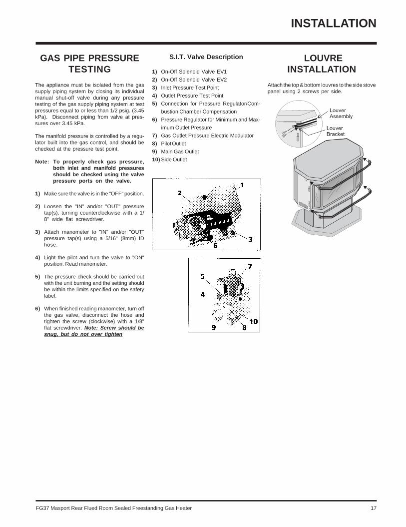
LOUVREINSTALLATION
Attach the top & bottom louvres to the side stovepanel using 2 screws per side.
GAS PIPE PRESSURETESTING
The appliance must be isolated from the gassupply piping system by closing its individualmanual shut-off valve during any pressuretesting of the gas supply piping system at testpressures equal to or less than 1/2 psig. (3.45kPa). Disconnect piping from valve at pres-sures over 3.45 kPa.
The manifold pressure is controlled by a regu-lator built into the gas control, and should bechecked at the pressure test point.
Note: To properly check gas pressure,both inlet and manifold pressuresshould be checked using the valvepressure ports on the valve.
1) Make sure the valve is in the "OFF" position.
2) Loosen the "IN" and/or "OUT" pressuretap(s), turning counterclockwise with a 1/8" wide flat screwdriver.
3) Attach manometer to "IN" and/or "OUT"pressure tap(s) using a 5/16" (8mm) IDhose.
4) Light the pilot and turn the valve to "ON"position. Read manometer.
5) The pressure check should be carried outwith the unit burning and the setting shouldbe within the limits specified on the safetylabel.
6) When finished reading manometer, turn offthe gas valve, disconnect the hose andtighten the screw (clockwise) with a 1/8"flat screwdriver. Note: Screw should besnug, but do not over tighten
S.I.T. Valve Description
1) On-Off Solenoid Valve EV1
2) On-Off Solenoid Valve EV2
3) Inlet Pressure Test Point
4) Outlet Pressure Test Point
5) Connection for Pressure Regulator/Com-
bustion Chamber Compensation
6) Pressure Regulator for Minimum and Max-
imum Outlet Pressure
7) Gas Outlet Pressure Electric Modulator
8) Pilot Outlet
9) Main Gas Outlet
10) Side Outlet

18 FG37 Masport Rear Flued Room Sealed Freestanding Gas Heater
FINAL CHECK
Before leaving this unit with the customer, theinstaller must ensure that the appliance is firingcorrectly. This includes:
1) Clocking the appliance to ensure the cor-rect firing rate (rate noted on label) at 15minutes.
2) If required, adjusting the primary air toensure that the flame does not carbon. Firstallow the unit to burn for 15 min. to stabilize.
CAUTIONAny alteration to the product that causessooting or carboning that results in dam-age to the exterior facia is not the respon-sibility of the manufacturer.
INSTALLATION
WIRINGCAUTION: Label all wires prior todisconnection when servicing con-trols. Wiring errors can cause im-proper and dangerous operation.
WARNING: Electrical Grounding InstructionsThis appliance is equipped with a three pronged (grounding) plug for your protection against shock hazard and should beplugged directly into a properly grounded three-prong receptacle. Do not cut or remove the grounding prong from this plug.
This heater does not require a 240V A.C. supplyfor the gas control to operate. A 240V A.C.power supply is needed for the fan/bloweroperation.
Caution: Ensure that the wires donot touch any hot surfaces and areaway from sharp edges.
OPTIONALREMOTE CONTROL
Use the Masport Remote Control Kit approved forthis unit. Use of other systems may void yourwarranty.
The remote control kit comes with a hand heldtransmitter and a wall mounting plate.
1) Choose a convenient location to mount thehand held transmitter, protection from extremeheat is very important.
The remote can also be used as a wall thermostat.
PILOT
FLAME SENSORSPARK IGNITOR
TO SIT 845 VALVE
BLUE (NEUTRAL)
BROWN (ACTIVE)
GREEN
BLUE
BLACK
RED
WHITEFAN
VIOLET
LOW SPEED
HIGH SPEED
BROWN
VIOLET
VIOLET
YELLOW
2
JUMPER
RESET SWITCH (NC)YELLOW
1 1112 10 89 7 56 4
BLACKBLACK
23 1
ORANGE
ORANGE
ORANGE
ORANGE
MODULE - GROUND
MODULE - FLAME
MODULE - SPARK
GREEN
RED
RED
IGNITION MODULE: S.I.T. #0.537.201
VALVE:- S.I.T. SIGMA 845
ON/OFF
FAN
FLAME
+ -
+ -
BLU
EC
OVER
MANUAL CONTROL
MED FAN
NEUTRALNEUTRAL
Ele
ctro
nic
Co
ntro
l Mo
dule
ACTIVE
LOW
THERM
HIGH
TH2
TH1
MOD1MOD2
GND
GND
GND
GND

FG37 Masport Rear Flued Room Sealed Freestanding Gas Heater 19
OPERATING INSTRUCTIONS
FIRST FIRE
The FIRST FIRE in your heater is part of the paintcuring process. To ensure that the paint isproperly cured, it is recommended that youburn your fireplace for at least four (4) hoursthe first time you use it with the fan on.
When first operated, the unit will release anodour caused by the curing of the paint and theburning off of any oils remaining from manufac-turing. Smoke detectors in the house may go offat this time. Open a few windows to ventilatethe room for a couple of hours. The glass mayrequire cleaning.
NOTE: The main burner will always start on"HIGH" and resume it's last setting after20 seconds of operation.
NOTE: When the glass is cold and the appli-ance is lit, it may cause condensationand fog the glass. This condensation isnormal and will disappear in a fewminutes as the glass heats up.
DO NOT ATTEMPT TO CLEAN THE GLASSWHILE IT IS STILL HOT!
DO NOT BURN THE APPLIANCE WITH-OUT THE GLASS FRONT IN PLACE.
OPERATINGINSTRUCTIONS
Before operating this appliance, proceedthrough the following check list.
1) Read and understand these Instructionsbefore operating this appliance.
2) Check to see that all wiring is correct andenclosed to prevent possible shock.
3) Check to ensure there are no gas leaks.
4) Make sure the three pieces of door glassare properly positioned. Never operate theappliance with any of the glass removed orwith the door open.
5) Verify that all flueing and the cap is unob-structed.
6) Verify log placement.
LIGHTINGINSTRUCTIONS
1) Plug the power cord into a power outlet.
2) Press and release the ON/OFF button onceto start the unit.
3) After approximately 3 seconds the sparkignition system will spark for 40 seconds tolight the main burner.
4) If the main burner does not light, reset theunit.
RESETTINGTHE UNIT
1) Open the pedestal door on the unit.
2) Press the reset button for approximately 3seconds and release. The reset button islocated on the unit's control panel.
3) Wait for approximately 3 seconds and thepilot sparks can be heard and seen. It wouldtake 2 to 3 seconds for the flame to be lit.
SHUTDOWNINSTRUCTIONS
1) Press the ON/OFF button once.
2) Turn off all electric power to the applianceif service is to be performed.
FAN OPERATION
Set the fan speed on the control panel locatedin behind the pedestal door to adjust fan to thedesired speed.
ADJUSTING FLAMEHEIGHT
There are six flame settings that can be adjust-ed by pressing and releasing the plus (+) andminus (-) FLAME button.
The FLAME setting button is located on thecontrol panel in behind the pedestal door.
Pressing and releasing the plus (+) FAN buttonwill change the fan speed as follows:
OFF -> LOW -> MEDIUM -> HIGH -> OFF, etc.
Pressing and releasing the minus (-) FAN buttonwill be the reverse of the above.
Control Panel

20 FG37 Masport Rear Flued Room Sealed Freestanding Gas Heater
NORMAL OPERATINGSOUNDS OF
GAS APPLIANCES
It is possible that you will hear some soundsfrom your gas appliance. This is perfectly nor-mal due to the fact that there are various gaugesand types of steel used within your appliance.Listed below are some examples. All are nor-mal operating sounds and should not beconsidered as defects in your appliance.
Blower:Masport gas appliances use high tech blowersto push heated air farther into the room. It is notunusual for the fan to make a "whirring" soundwhen ON. This sound will increase or decreasein volume depending on the speed setting ofyour fan speed control.
Burner Tray:The burner tray is positioned directly under theburner tube(s) and logs and is made of adifferent gauge material from the rest of thefirebox and body. Therefore, the varying thick-nesses of steel will expand and contract atslightly different rates which can cause "tick-ing" and "cracking" sounds. You should also beaware that as there are temperature changeswithin the unit these sounds will likely re-occur.Again, this is normal for steel fireboxes.
Gas Control Valve:As the gas control valve turns ON and OFF, adull clicking sound may be audible, this is normaloperation of a gas regulator or valve.
Unit Body/Firebox:Different types and thicknesses of steel willexpand and contract at different rates resultingin some "cracking" and "ticking" sounds will beheard throughout the cycling process.
SUMMARY OFCONTROLS
On/Off Button:If the unit is switched off, pressing and releas-ing this button once will switch the unit on. Theunit will resume its last settings.
If the unit is switched on, pressing and releas-ing this button once will switch the unit off.
Flame:Increase - If the unit is switched on, pressingand releasing the flame plus (+) button once willincrease the flame height to the next availablehigh setting.
Decrease - If the unit is switched on, pressingand releasing the flame minus (-) button oncewill decrease the flame height to the nextavailable low setting.
Fan:Increase - If the unit is switched on, pressingand releasing the fan plus (+) button once willincrease the fan speed to the next availablehigh setting.
Decrease - If the unit is switched on, pressingand releasing the fan minus (-) button once willdecrease the fan speed to the next availablelow setting.
PILOT ADJUSTMENT
Periodically check the pilot flames. The correctflame pattern has 3 strong blue flames.
One flowing around the thermocouple, the sec-ond flowing across the rear of the burner (itdoes not have to be touching the burner) andthe third flame flowing tangent to the sparkignitor.
NOTE: If you have an incorrect flamepattern, contact your Masport dealer forfurther instructions.
Rear of Burner
Front of Burner
An incorrect flame pattern will have small,probably yellow flames, not coming intoproper contact with the rear of the burner orthermopile.
Rear of Burner
Front of Burner
OPERATING INSTRUCTIONS

FG37 Masport Rear Flued Room Sealed Freestanding Gas Heater 21
COPY OF THE LIGHTING PLATE INSTRUCTIONS
OPERATING INSTRUCTIONS
WARNING:DO NOT SPRAY AEROSOLS IN THE VICINITY OF
THIS APPLIANCE WHILE IN OPERATION.
FOR YOUR SAFETY READ BEFORE LIGHTING
A) BEFORE LIGHTING smell all around the appliancearea for gas. Be sure to smell next to the floorbecause some gas is heavier than air and willsettle on the floor.
WHAT TO DO IF YOU SMELL GAS- Do not try to light any appliance- Do not touch any electric switch, do not use anyphone in your building- Immediately call your gas supplier from aneighbors phone. Follow the gas supplier’s in-structions.- If you cannot reach your gas supplier, call thefire department.
918-332
WARNING: If you do not follow these instructions exactly, a fire or explosion may resultcausing property damage, personal injury or loss of life. Improper installation, adjustment,alteration, service or maintenance can cause injury or property damage. Refer to theowner’s information manual provided with this appliance. For assistance or additionalinformation consult a qualified installer, service agency or gas supplier.
B) Do not use this appliance if any part has beenunder water. Immediately call a qualified servicetechnician to inspect the appliance and to replaceany part of the control system and any gas controlwhich has been under water.
This appliance needs fresh air for safe operationand must be installed so there are provisions foradequate combustion and ventilation air.
LIGHTING INSTRUCTIONS
TO TURN OFF GAS APPLIANCE
This appliance must be installed in accordance with local codes, if any; if not,follow the current CAN1-B149/ANSI Z 223.1 (Australia: AG601, New Zealand: NZS 5261)
DO NOT REMOVE THIS INSTRUCTION PLATE
1) Press the ON/OFF button once.
CAUTION: Hot while in operation. Do not touch. Severe Burns may result. Due to high surfacetemperatures keep children, clothing and furniture, gasoline and other liquids havingfammable vapors away. Keep burner and control compartment clean. See installation andoperating instructions accompanying appliance.
STOP! Read the safety information above on this label.
1) Plug the power cord into a power outlet.
2) Press and release the ON/OFF button once tostart the unit.
3) After approximately 3 seconds the sparkignition system will spark for 40 seconds tolight the main burner.
4) If the main burner does not light, check thegas and reset the unit.
2) Turn off all electric power to the unit ifservice is to be performed.

22 FG37 Masport Rear Flued Room Sealed Freestanding Gas Heater
MAINTENANCE
CAUTION: ANY SAFETY SCREENOR GUARD REMOVED FOR SERV-ICING AN APPLIANCE MUST BEREPLACED PRIOR TO OPERAT-ING THE APPLIANCE.
CLOTHING OR OTHER FLAMMA-BLE MATERIAL SHOULD NOT BEPLACED ON OR NEAR THE APPLI-ANCE.
DO NOT USE THIS APPLIANCE IFANY PART HAS BEEN UNDERWATER. IMMEDIATELY CALL ANAUTHORIZED SERVICE TECHNICIAN TO INSPECT THE APPLI-ANCE AND TO REPLACE ANY PARTOF CONTROL SYSTEM AND ANYGAS CONTROL WHICH HAS BEENUNDER WATER.
WARNING: CHILDREN ANDADULTS SHOULD BE ALERTED TOTHE HAZARDS OF HIGH SURFACETEMPERATURE AND SHOULDSTAY AWAY TO AVOID BURNS ORCLOTHING IGNITION. YOUNGCHILDREN SHOULD BE CAREFUL-LY SUPERVISED WHEN THEY AREIN THE SAME ROOM AS THE AP-PLIANCE.
MAINTENANCEINSTRUCTIONS
Any maintenance required accessing theglass door of the unit must be performed byan authorized service person.
1) Always unplug the power cord beforecleaning. For relighting, refer to lightinginstructions. Keep the burner and controlcompartment clean by brushing and vac-uuming at least once a year. When cleaningthe logs, use a soft clean brush as the logsare fragile and easily damaged.
2) Clean glass (never when unit is hot), ap-pliance, louvres, and door with a dampcloth. Never use an abrasive cleaner. Thegold louvres (and optional gold door) maybe scratched if abrasives are used toclean them.
The heater is finished in a heat resistantpaint and should only be refinished withheat resistant paint (not with wall paint).Masport uses StoveBright Paint - MetallicBlack #6309.
3) Make a periodic check of burner for properposition and condition. Visually check theflame of the burner periodically, makingsure the flames are steady; not lifting orfloating. If there is a problem, call an author-ized service person.
4) The appliance and flueing system must beinspected before use, and at least annual-ly, by an authorized field service person,to ensure that the flow of combustion andventilation air is not obstructed.
During the annual service call, the burnersshould be removed from the burner trayand cleaned. Replace the embers - do notblock the pilot or burner ports.
5) Keep the area near the appliance clear andfree from combustible materials, gasolineand other flammable vapours and liquids.
6) Verify proper operation after servicing.
GOLD-PLATED DOORS
The 24 carat gold plated finish on the doorrequires little maintenance, and need only becleaned with a damp cloth. DO NOT useabrasive materials or chemical cleaners, asthey may harm the finish and will void thewarranty. Clean any fingerprints off beforeturning the unit on.

FG37 Masport Rear Flued Room Sealed Freestanding Gas Heater 23
LATCH ADJUSTMENT
The door latch may require adjustment as thedoor gasket material compresses after a fewfires and after glass replacement. Turn thehandle on the adjustable catch to tighten orloosen the latch.
Installing Glass
1) Install both center and side glass ontoextrusions as per diagram.
2) Place glass assembly into door frame.
3) Install retainers by placing 1 drop of gluewhere previously glued and put in place.
4) Install side retainers.
5) Install door catch plate.
6) Install the 24 nuts loosely, do not tightenyet.
7) Tighten side panels nuts using the follow-ing procedure:
a. tighten top & bottom outside cornernuts (2)
b. tighten inside nuts (3)c. tighten top & bottom inside corners (2)
PANEL DOOR
1) Remove the door from the unit and place ona soft surface to prevent scratching.
2) Pull out the door gasket.
3) Remove the nuts holding the glass retain-ers in place.
4) Remove the glass retainers (sides, top andbottom) and the door catch plate.
5) Replace the glass. The glass must havegasketing around it.
6) Reverse the previous steps, replace theretainers and fasten with the nuts but donot overtighten, as this can break theglass. Note: the door catch plate fits on topof the left side retainer.
7) Put gasket glue on the retainers, but do notput glue on the screws. Replace the doorgasket, the two ends butt tight together onthe bottom edge of the door.
8) Replace door on the stove and check theseal.
8) Tighten the 10 nuts on center glass retain-er.
9) Repeat step 7 for other side panel.
10) Replace new gasket by gluing it in place.
11) Install door onto stove and check the seal.
MAINTENANCE
LOG REPLACEMENT
The unit should never be used with broken logs.Turn off the gas valve and allow the unit to coolbefore opening door to carefully remove thelogs. The pilot light generates enough heat toburn someone. If for any reason a log shouldneed replacement, you must use the properreplacement log. The position of these logsmust be as shown in the diagram under LogInstallation.
Note: Improper positioning of logs maycreate carbon build-up and will al-ter the unit’s performance whichis not covered under warranty.
GLASS REPLACEMENT
Your Masport stove is supplied with high tem-perature, 5 mm Neoceram ceramic glass thatwill withstand the highest heat that your unit willproduce. In the event that you break your glass,purchase your replacement from an authorizedMasport dealer only, and follow the step-by-step instructions for replacement.
Never operate your unit with bro-ken glass.
WARNING: Do not operate appli-ance with the glass front removed,cracked or broken. Replacement ofthe glass should be done by a li-censed or qualified service person.
MITRED DOOR
Removing Glass:
Note: Wearing gloves will protect yourhands while handling glass.
1) Remove the door from the unit and place ona soft surface to prevent scratching.
2) Pull out the door gasket.
3) Remove the 24 nuts holding the glass retain-ers in place. Do not remove the nuts under-neath the retainers.
4) Remove the door catch plate.
5) Remove glass retainers on sides first (3each side) then remove two center retain-ers.
Note: Center glass retainers are gluedto center glass.
6) Remove glass from extrusions. When re-moving center glass, leave white insulationin place.

24 FG37 Masport Rear Flued Room Sealed Freestanding Gas Heater
MAINTENANCE
FAN MAINTENANCE
If your fan requires maintenance or replace-ment it must be performed by an authorisedperson. Access to the fan is through the plateon the rear wall of the firebox. NOTE: the unitMUST NOT be operated without the fanaccess panel securely in place and cor-rectly sealed.
IMPORTANT: These fans collect alot of dust from within your home.Ensure you maintain these fan mo-tors on a regular basis by vacuum-ing out the fan squirrel cages, aroundthe motor, and around the grills onthe back of the stove.
TO REMOVE FAN
1) Unplug or disconnect power source tostove.
2) Remove the rear access panel on the backof the stove. The fan can only be accessedfrom the back of the stove.
IMPORTANTDisconnect power supply
before servicing.
WARNING:Electrical Grounding InstructionsThis appliance is equipped witha three pronged (grounding) plugfor your protection against shockhazard and should be pluggeddirectly into a properly groundedthree-prong receptacle. Do notcut or remove the groundingprong from this plug.
3) Unclip the wires from the fan motor.
4) Lift fan off of the 2 pins, tip back and pullthrough the opening. Disconnect the greenground wire from the right side of the fanas soon as you can reach it.
REPLACING FAN
Reverse the above steps (1 - 4). Make sure thefan wires and the ground wire are reattached.
Hint for pushing fan down onto pins - rub a bitof dish soap on the grommet so it will slidemore easily onto the pin. Check to make surethe fan is seated properly on the pins - try tomove the fan back and forth, there should beno noise, if there is check that the grommetshaven't come loose.

FG37 Masport Rear Flued Room Sealed Freestanding Gas Heater 25
MAINTENANCE
4) Remove the two outside frame pieces byremoving two screws per side. See dia-gram below.
REMOVING VALVE TRAY
If your valve requires maintenance or replace-ment, follow these instructions:
NOTE: Always shut off the gas and dis-connect the power supply beforeremoving the valve.
1) Open the front door and carefully removethe logs and lava rock.
2) Remove the burner by removing the two1/4" hex head screws. See diagram below.
3) Open the front pedestal door and unhookchain. You may want to put a soft cloth onthe base of the unit so that when thepedestal door is open it doesn't scratch thepaint. See diagram below.
5) Remove the front plate by undoing the 6screws.
6) Disconnect the manual switch cable andreset cables.
7) Disconnect the gas pipe line at the valve.
8) Remove the pedestal back cover by remov-ing the 4 Philips screws.
9) Disconnect the 5 pin molex connector.
10) Disconnect the ground wires.
11) Remove the 20 x 1/4" hex head screwsholding the burner tray assembly in place.
12) Carefully lift the burner tray assembly out.
13) To replace the burner tray assembly,reverse these instructions.
Reset Cables
GroundWire
5 PinMolex Connector
Manual SwitchCable

26 FG37 Masport Rear Flued Room Sealed Freestanding Gas Heater
PARTS LIST
1) 560-920 Louvre Assy (Set) - Gold560-922 Louvre Assy (Set) - Black
4) 730-038 Door Screen (Australia Only)8) 730-560 Relief Door Assembly10) 640-034 Mounting Plate Gasket
560-519/P Fan Assembly (240 V)11) 910-169/P Fan Motor (240 V)12) 910-714 Power Cord (240 V)
Pedestal Assembly16) 730-039 Pedestal Door17) 904-257 Pedestal Door Magnet18) 560-025 Pedestal Back
19) 730-530 Side Panel Door Assy(Right Side)
20) 730-525 Side Panel Door Assy(Left Side)
21) 560-031 Side Panel Door Hinge23) 904-258 Side Panel Door Magnet24) 948-255 Door Latch - c/w J-Hook
FG37 MAIN ASSEMBLY Part # Description Part # Description Part # Description
25) * Flex Pipe (3" ID)26) * Clamp for Flex Pipe27) 910-233 Fan Auto On/Off
Thermodisc28) * Mounting Brckt-Thermodisc29) * Air Deflector30) 680-030 Rear Panel31) 630-021 Fan Access Panel32) 730-565 Firebox Baffle/RestrictorAssembly33) 640-520 False Top Assembly35) 630-011 Air Passage Gasket38) 820-058 Pedestal Base Cover40) 730-042 Thermodisc Cover41) 904-185 Cable Tie - High Temperature42) 904-186 Cable Tie Mounting Button
910-033 Heat Resistant Sleeve45) 750-031 Rear Control Panel50) 910-140 Fan Hi/Off/Low Switch51) 910-246 Burner On/Off Switch
680-969 Conversion Kit - To LPG948-216 Logo Plate918-089 Decal-Top Rear Control Panel918-318 Manual
*Not available as a replacement part.

FG37 Masport Rear Flued Room Sealed Freestanding Gas Heater 27
FG37 BURNER & LOG ASSEMBLY
52) 910-190 Piezo Ignitor & Nut54) 910-373 Knob - Pilot Valve Extension55) 910-372 Flame Adjusting Knob56) 918-088 Decal - Control Panel57) 591-041 Switch Plate
680-574/P Valve Assembly - NG680-576/P Valve Assembly - LPG
60) 910-378 Valve - S.I.T. - NG904-240 #37 Orifice - NG936-170 Orifice Gasket
67) * Pilot Holder68) W840470 Pilot Assembly Gasket71) 730-528 Log Stand
904-390 Pilot Orifice #52 - NG75) 730-935 Log Set78) 730-550 Burner Assy - NG/LP
Part # Description Part # Description
PARTS LIST
82) 630-009 Gasket - Burner Tray / Air Passage83) 630-008 Gasket - Burner Tray / Firebox
90) 910-386 Thermocouple91) 910-341 Thermopile
69) 730-935 Log Set92) Rear Log93) Left Top Log94) Center Log95) Middle Right Log96) Middle Left Log97) Front Right Log98) Front Left Log
*Not available as a replacement part.

28 FG37 Masport Rear Flued Room Sealed Freestanding Gas Heater
FG37 DOOR ASSEMBLIES
Part # Description
PARTS LIST
730-924 Gold Mitred Door - Complete730-926 Black Mitred Door - Complete730-932 Gold Wrap Door - Complete730-928 Gold Panel Door - Complete
101) 650-920 Door Gasket Kit105) * Ceramic Paper106) 940-323/P Side Glass107) 936-243 Glass Gasket108) 940-322/P Centre Glass111) * Door Frame Fibre Paper112) 750-015 Door Glass Extrusion208) 940-325/P Wrap Glass
*Not available as a replacement part.

FG37 Masport Rear Flued Room Sealed Freestanding Gas Heater 29
_____________________________________________________________________________________
____________________________________________________________
__________________________________________________________
____________________________________________________________
_______________________________________________________
_____________________________________________________
__________________________________________________________
_________________________________________________________
_________________________________________________________
______________________________________________________
______________________________________________________
_______________________________________________________________
___________________________________________________________
__________________________________________________________
____________________________________________________________
____________________________________________________________
____________________________________________________________
_____________________________________________________________
__________________________________________________________
__________________________________________________________
_____________________________________________________
________________________________________________________
_________________________________________________________
_________________________________________________________
NOTES

30 FG37 Masport Rear Flued Room Sealed Freestanding Gas Heater
_____________________________________________________________________________________
____________________________________________________________
__________________________________________________________
____________________________________________________________
_______________________________________________________
_____________________________________________________
__________________________________________________________
_________________________________________________________
_________________________________________________________
______________________________________________________
______________________________________________________
_______________________________________________________________
___________________________________________________________
__________________________________________________________
____________________________________________________________
____________________________________________________________
____________________________________________________________
_____________________________________________________________
__________________________________________________________
__________________________________________________________
_____________________________________________________
________________________________________________________
_________________________________________________________
_________________________________________________________
NOTES

FG37 Masport Rear Flued Room Sealed Freestanding Gas Heater 31
WARRANTY
THE MASPORT EXPRESS WARRANTY
All new Masport Gas appliances are warranted, subject to thefollowing conditions, to be free from defects in material orworkmanship under normal use. The Express Warranty on allparts, including firebox components but excluding fans, fluesand flue accessories is two years from date of originalpurchase as well as labour costs involved in the repair orreplacement. The Express Warranty on fans, flues and acces-sories is for a period of twelve months from date of originalpurchase and includes labour costs involved in the repair orreplacement.
This Express Warranty applies only with respect to defects inmaterial and workmanship under normal and proper use ofthe NEW UNIT in its unmodified condition. Masport's obliga-tion under this Express Warranty is limited to the repair orreplacement, at its option, by an approved Masport GasService Agent (Retailer) of any part found to be defective inmaterial or workmanship.
Labour costs involved in the repair or replacement are alsocovered under this Express Warranty as per the time conditionoutlined.
If an approved Masport Gas Service Agent is requested toattend on a service call that is not covered under this ExpressWarranty, a call out charge may be applicable, regardless ofwhether a repair is carried out or not.
Masport can accept no obligation whatsoever for any inciden-tal, consequential or special damages or expenses resultingfrom any product defect. This Express Warranty applies fromthe date of original purchase, applies to the original purchas-er, and is not transferable. The decision to repair or replacedefective components will be made by Masport or its agentand actioned by an approved Masport Service Agent.
This Express Warranty Does Not Cover:1. Defects, malfunctions or failures caused by incorrect installa-
tion, normal wear and tear, misuse, neglect, accidental dam-age or failure to follow the fuel selection, product operating andmaintenance instructions, or resulting from installations, re-pairs or modifications to the equipment carried out by unau-thorised persons.
2. Defects, malfunctions or failures caused by an act or omissionof other persons after the product has left Masport's control.
3. The costs of collection and delivery of the equipment.
4. The cost of labour or materials as a consequence of faultyinstallation of gas supply line, flue, burner or log settings, ornon-compliance with local codes.
The Express Warranty is not intended to exclude any rights thepurchaser may have under the laws of the place, state, orcountry of purchase. Nothing in this Express Warranty limits orrestricts any other statutory right or remedy available to thepurchaser.
How You Obtain Warranty Service:Provide proof of the date of purchase. Should the need for awarranty claim arise reasonable proof of the purchase date isrequired therefore you should retain your sales receipt. Whereflueless appliances are not permanently installed, they should bereturned to a Service Agent for evaluation.
Make the faulty part(s) available for inspection by Masport and/orits agents so that the validity of the claim can be established bythem.
Australia Distributor:
Masport Pty LimitedP.O. Box 533Braeside Victoria 3195
For your own records, please complete the following:
Model: ________________________________________ Serial Number: ____________________________
New Zealand:
Masport LimitedP.O. Box 14-349PanmureAuckland 6
Retailer: ________________________________________________________________________________
______________________________________________________________________________________
Purchase Date: _______________________________

Printed in Canada© Copyright 2004, FPI Fireplace Products International Ltd. All rights reserved.