Embed Size (px)
Citation preview

Gas permeability: A simple and efficient method for testing membranematerial/solvent compatibility for membrane contactors applications
Phuc Tien Nguyen�, Denis Roizard, Dominique Thomas, Eric FavreaLSGC (CNRS UPR 6811) Nancy Universite, 1 rue Grandville, 54001 Nancy, France. Tel. þ(33) 383 17 53 90; Fax þ(33) 383 32 29 75;email: [email protected]
Received 24 June 2009; accepted 5 November 2009
A B S T R A C T
The selection of the most efficient hydrophobic microporous material is a key issue for membranecontactors applications. This holds especially for intensified gas–liquid absorption operations forwhich stable membrane performances such as non wetting conditions or effective gas permeabil-ity are demanded on a long time basis. In this study, the membrane material challenges of postcombustion carbon dioxide capture performed in a membrane contactor are developed with a30% aqueous MEA solution as chemical solvent. A simple, sensitive, non destructive and relevantexperimental technique based on gas permeability measurement is proposed in order to estimatemembrane / solvent compatibility. The interest of the technique is presented on ten differentmembrane materials; the materials screening step and the possibility to point out differences inmaterials ageing issues are shown.
Keywords: Membrane contactors; Polymers; Ageing; Carbon dioxide; Capture; Permeability
1. Introduction
The essential element in a membrane contactor isobviously the membrane material, which has to ensuremaximal interface area, minimal mass transfer resis-tance and stability in performances. Porous hydropho-bic membranes are preferred for this purpose becauseof their low-cost and wide availability. The key conceptof the process is based on the fact that the liquid absor-bent cannot penetrate the membrane because its poresare sufficiently small and the membrane materialrepels the liquid. In practical operation a gas streamis fed along one side of the membrane. The use of amembrane absorber leads to the following advantages:
• Gas and liquid flow are independent, resulting inavoidance of problems encountered in packed/tray
columns such as flooding, foaming, channelling andentrainment,
• Equipment will be compact through the use of a hol-low fibre membrane leading to specific surface areasin excess of 1,000 m2/m3 compared to 100–200 m2/m3.
The operational stability relates to the capability ofthe membrane contactor system to keep the interfacefor mass exchange intact and its performance stablefor a relevant operational period under the normaloperational conditions. One important item is thatpermeation of the solvent through the membraneshould not happen throughout the life-time becausethis will result in the loss of the operational benefitsof membrane contactors. Penetration of the membranepores by the solvent will indeed affect the performancesof the membrane contactor, because diffusion in gasfilled pores is much faster than in liquid filled pores.
�Corresponding author
Desalination and Water Treatment 14 (2010) 1–10Februarywww.deswater.com
1944-3994/1944-3986 # 2010 Desalination Publications. All rights reserveddoi: 10.5004/dwt.2010.1006
Presented at the Fourth Membrane Science and Technology Conference of Visegrad Countries (PERMEA 2009), Prague, 7-11June, 2009.

This study will more specifically address the mem-brane stability issues over long time operation, whichare determined by:
1. Critical entry pressureThe critical entry pressure is the excess liquid side
pressure at which the solvent will penetrate the mem-brane pores. For porous membranes with uniformcylindrical pores, this is governed by the so-calledLaplace equation:
�P ¼ �2 g=rð Þ cos � ð1Þ
in which �P: Transmembrane pressure, [N/m2]
g: Surface tension of liquid, [N/m]r: Pore radius, [m]�: Contact angle, [�]
The contact angle results from the physical affinitybetween the solvent and the membrane material. Ahigh value indicates a low affinity between the solventand the membrane material. Eq. (1) shows that themembrane pores will not be wetted if the contact-angle is greater than 90�. At contact angles in excessof 90�, Eq. (1) gives the break-through pressure as afunction of solvent surface tension and pore size. Con-sequently, suitable membrane materials for aqueousabsorption liquids are non-polar polymers, such as,poly-propylene (PP), poly-ethylene (PE) and poly-tetrafluorethylene (PTFE). It is important to stress thatthe critical entry pressure is determined by the largestpores. The knowledge of the pore size distribution (andnot only the average pore size) is thus of major impor-tance in that context.
2. Chemical interaction between membrane materialand solventSome solvents will react with the membrane mate-
rial over a prolonged period of exposure. It is clear thatsuch membrane-solvent combinations are not practi-cal. For instance, polypropylene materials have beenoccasionally reported to slowly react with DEA [1],which suggests that this membrane material / solventcombination is not feasible.
3. TemperatureA higher temperature will lead to a lower surface
tension of the solvents and, therefore, a lower criticalentry pressure. The chemical stability will also be influ-enced by temperature. Furthermore, it is known thatoxygen induced membrane degradation and at highertemperature, this phenomena is faster.
Apart from the stability issues which have beendiscussed above, the ideal material for membrane
contactor applications should also offer the smallestmass transfer resistance (i.e. the largest mass transfercoefficient). Different methods have been investigatedin order to determine the mass transfer coefficient kmand three of them are described hereafter.
Generally speaking, the membrane mass transfercoefficient for a specific type of porous membranedepends on the porosity, thickness and tortuosity [2]:
km ¼ Dg;e � "=t:z ð2Þ
where Dg,e: Effective diffusion coefficient in gas filledpores, [m2/s]
z: Membrane thickness, [m]": Membrane porosity, [–]t: Membrane tortuosity, [–]
The effective diffusion coefficient is determinedthrough a combination of bulk diffusion and Knudsendiffusion. Bulk (or molecular) diffusion describes theinteraction between the gas molecules; Knudsen diffu-sion describes the interaction between the gas mole-cules with the pore walls.
1=Dg;e ¼ 1=Dg;b þ 1=Dk ð3Þ
where Dg,b: Bulk diffusion coefficient, [m2/s]Dk: Knudsen diffusion coefficient, [m2/s]
which can be written as
Dk ¼ 1=3 � dpð8RT=pMÞ0:5 ð4Þ
with dp: Pore diameter, [m]
R: Gas constant, [J/kmol.K]T: Temperature, [K]M: Molecular mass, [kg/kmol]
The membrane mass transfer coefficient is deter-mined by the choice of membrane through the porosityand tortuosity. In general, the porosity should be highand tortuosity should be low, but the membraneshould still have sufficient mechanical strength. Thepore diameter can also have impact through the Knud-sen diffusion coefficient. However, porosity, tortuosityand pore diameter are often unknown because of thedifficulty to determine them precisely and of the largepore size distribution.
Given the difficulty to predict the membrane masstransfer coefficient, experimental methods have beendeveloped. A first approach, developed by Qi andCussler [3] is an indirect method based on permeationof pure gas in a liquid so that the mass transfer resis-tance in the gas phase 1/kg can be neglected. The
2 P.T. Nguyen et al. / Desalination and Water Treatment 14 (2010) 1–10
mass transfer coefficient in the liquid phase kl is thencalculated by a selected correlation and km can finallybe deduced from the overall mass transfer coefficient K(which is experimentally determined). The resulting km
value combines the imprecision due to the experimentsand also the uncertainty of the mass transfer correla-tions which can induce a large range of km.
Another approach is based on a direct experimentalmethod, only studied for transmembrane distillationoperation by Guijt et al. [4]. It considers the permeationof a pure gas in short hollow fibers in order to suppressthe influence of the mass transfer resistance in the gasphase, see Fig. 1.
The contribution of both Knudsen diffusion and vis-cous flow are taken into account in the calculation ofthe total gas flux through the pores:
N ¼ � 1=RTð Þ K0�M þ B0 P=mð Þ½ �rP ð5Þ
with N: Molar gas flux, [mol/m2.s]
K0: Knudsen diffusion morphology parameter, [m]B0: Viscous flow morphology parameter, [m2]P: Pressure, [Pa]
m: Viscosity, [Pa.s]rP: Derivative from P in all directions, [Pa/m]�M: Mean Knudsen molecular velocity, [m/s]with:
�M ¼ ð8RT=pMÞ1=2 ð6Þ
From a practical point of view, a short review of theliterature shows a wide range of km data. Indeed,Kumar et al. [5] estimated a value of 4.62�10�2 m/s,Qi and Cussler [3] measured a value of 5.1�10�3 m/sand Lin et al. [6] calculated values from 4.37�10�4 to1.14�10�3 m/s for a PP membrane. Yeon and al. [7]reported a value of 5�10�4 m/s for PTFE and 10�3 m/s for PVDF and Lin et al. [6] estimated values from10�4 to 7�10�4 m/s for the latter material. These resultsillustrate the diversity of material used for membranecontactors applications and the large uncertainty of themembrane mass transfer coefficient measurements. Ina first step, we will address the measurement of mem-brane mass transfer coefficient of 10 different materialsthrough a simple gas permeability method. The stabi-lity of this parameter when the membrane is put intocontact with a solvent solution for a long time will beexposed and discussed in a second part.
2. Materials & methods
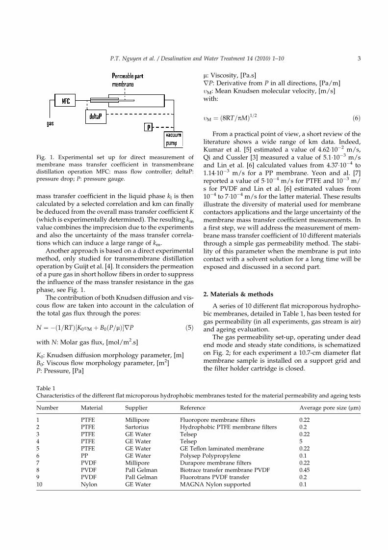
A series of 10 different flat microporous hydropho-bic membranes, detailed in Table 1, has been tested forgas permeability (in all experiments, gas stream is air)and ageing evaluation.
The gas permeability set-up, operating under deadend mode and steady state conditions, is schematizedon Fig. 2; for each experiment a 10.7-cm diameter flatmembrane sample is installed on a support grid andthe filter holder cartridge is closed.
Fig. 1. Experimental set up for direct measurement ofmembrane mass transfer coefficient in transmembranedistillation operation MFC: mass flow controller; deltaP:pressure drop; P: pressure gauge.
Table 1Characteristics of the different flat microporous hydrophobic membranes tested for the material permeability and ageing tests
Number Material Supplier Reference Average pore size (mm)
1 PTFE Millipore Fluoropore membrane filters 0.222 PTFE Sartorius Hydrophobic PTFE membrane filters 0.23 PTFE GE Water Telsep 0.224 PTFE GE Water Telsep 55 PTFE GE Water GE Teflon laminated membrane 0.226 PP GE Water Polysep Polypropylene 0.17 PVDF Millipore Durapore membrane filters 0.228 PVDF Pall Gelman Biotrace transfer membrane PVDF 0.459 PVDF Pall Gelman Fluorotrans PVDF transfer 0.210 Nylon GE Water MAGNA Nylon supported 0.1
P.T. Nguyen et al. / Desalination and Water Treatment 14 (2010) 1–10 3
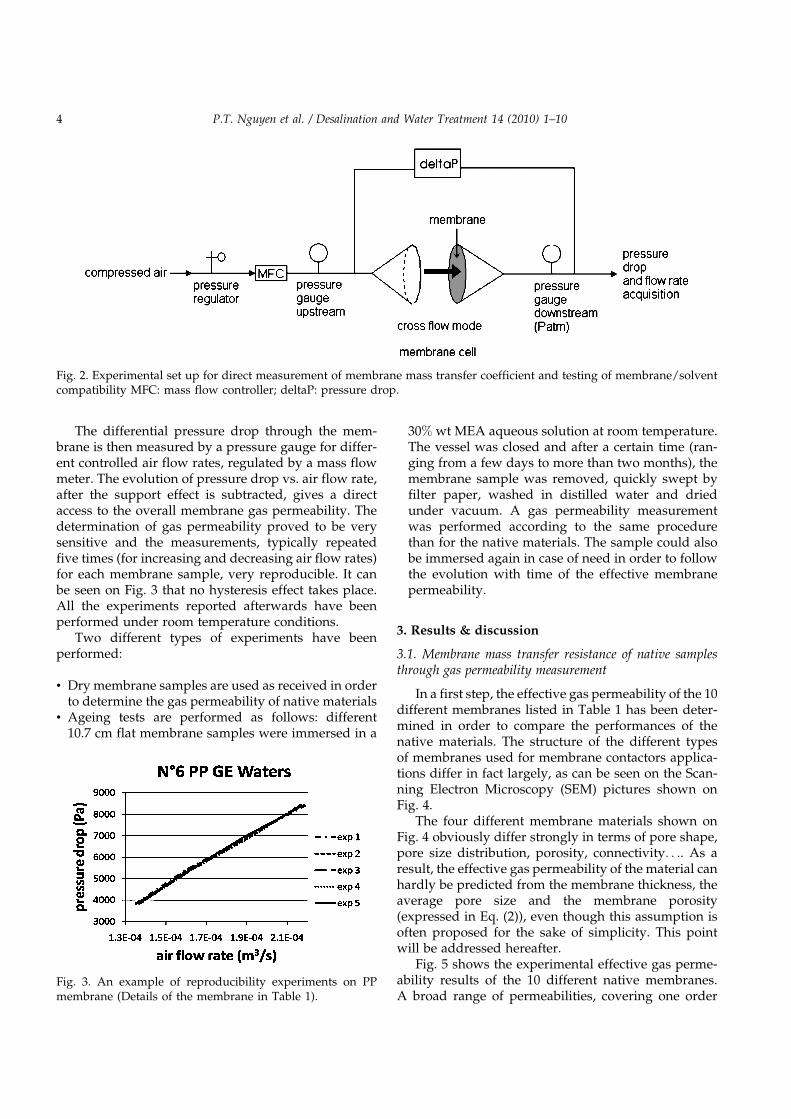
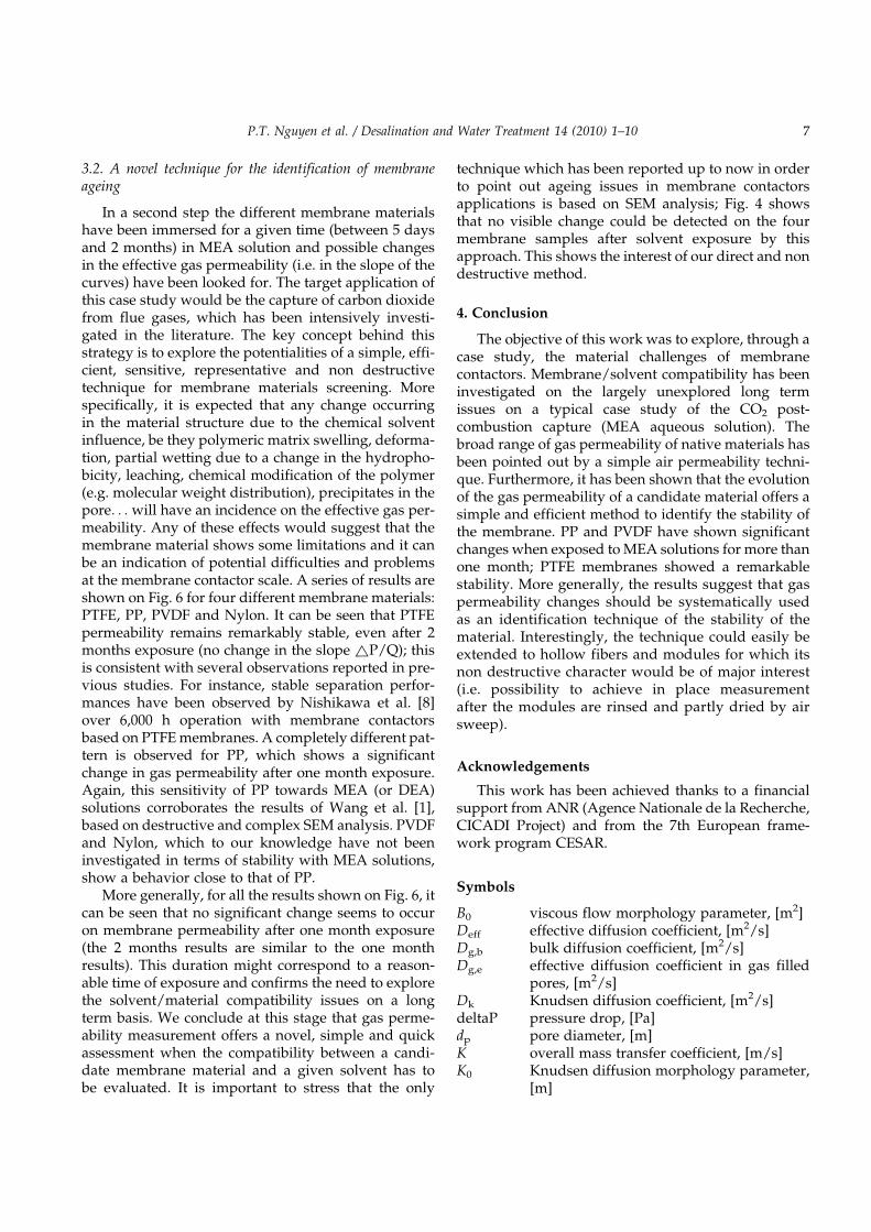
The differential pressure drop through the mem-brane is then measured by a pressure gauge for differ-ent controlled air flow rates, regulated by a mass flowmeter. The evolution of pressure drop vs. air flow rate,after the support effect is subtracted, gives a directaccess to the overall membrane gas permeability. Thedetermination of gas permeability proved to be verysensitive and the measurements, typically repeatedfive times (for increasing and decreasing air flow rates)for each membrane sample, very reproducible. It canbe seen on Fig. 3 that no hysteresis effect takes place.All the experiments reported afterwards have beenperformed under room temperature conditions.
Two different types of experiments have beenperformed:
• Dry membrane samples are used as received in orderto determine the gas permeability of native materials
• Ageing tests are performed as follows: different10.7 cm flat membrane samples were immersed in a
30% wt MEA aqueous solution at room temperature.The vessel was closed and after a certain time (ran-ging from a few days to more than two months), themembrane sample was removed, quickly swept byfilter paper, washed in distilled water and driedunder vacuum. A gas permeability measurementwas performed according to the same procedurethan for the native materials. The sample could alsobe immersed again in case of need in order to followthe evolution with time of the effective membranepermeability.
3. Results & discussion
3.1. Membrane mass transfer resistance of native samplesthrough gas permeability measurement
In a first step, the effective gas permeability of the 10different membranes listed in Table 1 has been deter-mined in order to compare the performances of thenative materials. The structure of the different typesof membranes used for membrane contactors applica-tions differ in fact largely, as can be seen on the Scan-ning Electron Microscopy (SEM) pictures shown onFig. 4.
The four different membrane materials shown onFig. 4 obviously differ strongly in terms of pore shape,pore size distribution, porosity, connectivity. . .. As aresult, the effective gas permeability of the material canhardly be predicted from the membrane thickness, theaverage pore size and the membrane porosity(expressed in Eq. (2)), even though this assumption isoften proposed for the sake of simplicity. This pointwill be addressed hereafter.
Fig. 5 shows the experimental effective gas perme-ability results of the 10 different native membranes.A broad range of permeabilities, covering one order
Fig. 2. Experimental set up for direct measurement of membrane mass transfer coefficient and testing of membrane/solventcompatibility MFC: mass flow controller; deltaP: pressure drop.
Fig. 3. An example of reproducibility experiments on PPmembrane (Details of the membrane in Table 1).
4 P.T. Nguyen et al. / Desalination and Water Treatment 14 (2010) 1–10

of magnitude and reflected by the different slopes isobtained. This first set of results has been used as thereference material permeability in what follows.
From these experiments, permeability and masstransfer coefficient in the membrane can be tentativelycalculated.
The starting point is the effective gas permeabilityof the membrane material, which can be obtained fromthe experimental results and is defined as:
P0 ¼ Qz=ð�PSÞ ð7Þ
with P’: Permeability, [m3.m/(m2.s.Pa)]
Q: Air flow rate, [m3/s]z: Membrane thickness, [m]~P: Transmembrane pressure, [Pa]
S: Surface, [m2]
It is obvious that the permeability calculated by thisway depends on the nature of the gas because of differ-ence of viscosity.
The membrane mass transfer coefficient km is oftenexpressed as:
km ¼ Deff=z ð8Þ
with Deff: Effective diffusion coefficient, [m2/s]Deff is calculated by equaling these two expressions:
N ¼ Deff�c=z ð9Þ
N ¼ P0 ��P= Vm � zð Þ ð10Þ
with ~c: Concentration difference, [mol/m3]
Vm: Molar volume, [m3/mol]
Based on this approach, the membrane mass trans-fer coefficient for a strict convection mass transfer,expressed in m/s, can be calculated (results are givenin Table 2).
It is of interest at this stage to explore how the diffu-sional mass transfer coefficient of the membrane,which is expected to hold for classical membranecontactors applications (no convection flux), could beestimated. Two sets of porosity/tortuosity data havebeen taken to calculate km in pure diffusion mode(Eq. (2)) and compare with the data obtained underpure convection mode.
The latter can be estimated based on the permeabil-ity of a set of monodispersed capillaries of porosity "and tortuosity ":
P0 ¼ " � dp2=32m � t ð11Þ
As the porosity is not provided by the supplier, 30%and 85% (which is a very high value) have been used.Additionally, tortuosity cannot be directly determinedand it can range between 1 (for straight pore geometry)and 10 in some cases. The pure convection valuesobtained through this calculation range from4.4�10�4 m/s to 0.21 m/s. The agreement of the highestvalue is rather fair with most of experimental data(Table 2).
Finally, the mass transfer coefficient data for purediffusion range, which are necessary for real mem-brane contactors applications, have been calculatedthrough Eq. (2) with a bulk diffusion coefficient of10�5 m2.s�1. The so obtained values range from0.002 m/s to 0.13 m/s and logically show larger valuesthan the experimental data reported in the literature,
Fig. 4. SEM pictures of four different membrane materials.Left: native samples. Right: Samples after 2 months exposurein MEA aqueous solutions Indications correspond to the listgiven in Table 1.
P.T. Nguyen et al. / Desalination and Water Treatment 14 (2010) 1–10 5

namely 5�10�4 to 5�10�2 m/s. The overestimation canbe expected to result from the diffusion coefficientsince Knudsen contribution has not been taken intoaccount. Unfortunately, similarly to other studies inthis field, pore size distribution is required for morerigorous and representative calculation to be per-formed. We conclude at this stage that direct gaspermeability measurement provides a fast and simple
method for a comparison between different materialsfor membrane contactors application. The predictionof a relevant mass transfer coefficient for diffusion con-ditions remains however difficult. In the next section,we describe the interest of the gas permeability methodfor a completely different purpose: the identification ofageing phenomena in membrane contactors applica-tions on a long time basis.
Fig. 5. Gas permeability results for the 10 different membrane materials (Membranes are detailed in Table 1).
Table 2Permeability and mass transfer measurements for the 10 different native membranes. The range of km values have beenobtained based on convective conditions (Eqs. 7–9)
Membrane number Average porediameter (mm)
Thickness (mm) Permeability(m3.m.m�2.s�1.Pa�1)
Permeability (barrer) km (m/s)
1 0.22 150 1.51E-09 2.02Eþ08 1.022 0.2 65 4.38E-10 5.84Eþ07 0.686 0.1 100 2.21E-10 2.94Eþ07 0.227 0.22 120 3.68E-10 4.90Eþ07 0.318 0.45 147 8.51E-10 1.13Eþ08 0.599 0.2 127 3.71E-10 4.95Eþ07 0.30
10 0.1 120 3.52E-10 4.69Eþ07 0.30
6 P.T. Nguyen et al. / Desalination and Water Treatment 14 (2010) 1–10
3.2. A novel technique for the identification of membraneageing
In a second step the different membrane materialshave been immersed for a given time (between 5 daysand 2 months) in MEA solution and possible changesin the effective gas permeability (i.e. in the slope of thecurves) have been looked for. The target application ofthis case study would be the capture of carbon dioxidefrom flue gases, which has been intensively investi-gated in the literature. The key concept behind thisstrategy is to explore the potentialities of a simple, effi-cient, sensitive, representative and non destructivetechnique for membrane materials screening. Morespecifically, it is expected that any change occurringin the material structure due to the chemical solventinfluence, be they polymeric matrix swelling, deforma-tion, partial wetting due to a change in the hydropho-bicity, leaching, chemical modification of the polymer(e.g. molecular weight distribution), precipitates in thepore. . . will have an incidence on the effective gas per-meability. Any of these effects would suggest that themembrane material shows some limitations and it canbe an indication of potential difficulties and problemsat the membrane contactor scale. A series of results areshown on Fig. 6 for four different membrane materials:PTFE, PP, PVDF and Nylon. It can be seen that PTFEpermeability remains remarkably stable, even after 2months exposure (no change in the slope ~P/Q); thisis consistent with several observations reported in pre-vious studies. For instance, stable separation perfor-mances have been observed by Nishikawa et al. [8]over 6,000 h operation with membrane contactorsbased on PTFE membranes. A completely different pat-tern is observed for PP, which shows a significantchange in gas permeability after one month exposure.Again, this sensitivity of PP towards MEA (or DEA)solutions corroborates the results of Wang et al. [1],based on destructive and complex SEM analysis. PVDFand Nylon, which to our knowledge have not beeninvestigated in terms of stability with MEA solutions,show a behavior close to that of PP.
More generally, for all the results shown on Fig. 6, itcan be seen that no significant change seems to occuron membrane permeability after one month exposure(the 2 months results are similar to the one monthresults). This duration might correspond to a reason-able time of exposure and confirms the need to explorethe solvent/material compatibility issues on a longterm basis. We conclude at this stage that gas perme-ability measurement offers a novel, simple and quickassessment when the compatibility between a candi-date membrane material and a given solvent has tobe evaluated. It is important to stress that the only
technique which has been reported up to now in orderto point out ageing issues in membrane contactorsapplications is based on SEM analysis; Fig. 4 showsthat no visible change could be detected on the fourmembrane samples after solvent exposure by thisapproach. This shows the interest of our direct and nondestructive method.
4. Conclusion
The objective of this work was to explore, through acase study, the material challenges of membranecontactors. Membrane/solvent compatibility has beeninvestigated on the largely unexplored long termissues on a typical case study of the CO2 post-combustion capture (MEA aqueous solution). Thebroad range of gas permeability of native materials hasbeen pointed out by a simple air permeability techni-que. Furthermore, it has been shown that the evolutionof the gas permeability of a candidate material offers asimple and efficient method to identify the stability ofthe membrane. PP and PVDF have shown significantchanges when exposed to MEA solutions for more thanone month; PTFE membranes showed a remarkablestability. More generally, the results suggest that gaspermeability changes should be systematically usedas an identification technique of the stability of thematerial. Interestingly, the technique could easily beextended to hollow fibers and modules for which itsnon destructive character would be of major interest(i.e. possibility to achieve in place measurementafter the modules are rinsed and partly dried by airsweep).
Acknowledgements
This work has been achieved thanks to a financialsupport from ANR (Agence Nationale de la Recherche,CICADI Project) and from the 7th European frame-work program CESAR.
Symbols
B0 viscous flow morphology parameter, [m2]Deff effective diffusion coefficient, [m2/s]Dg,b bulk diffusion coefficient, [m2/s]Dg,e effective diffusion coefficient in gas filled
pores, [m2/s]Dk Knudsen diffusion coefficient, [m2/s]deltaP pressure drop, [Pa]dp pore diameter, [m]K overall mass transfer coefficient, [m/s]K0 Knudsen diffusion morphology parameter,
[m]
P.T. Nguyen et al. / Desalination and Water Treatment 14 (2010) 1–10 7

kg mass transfer coefficient in the gas phase,[m/s]
kl mass transfer coefficient in the liquidphase, [m/s]
km mass transfer coefficient in the membrane,[m/s]
M molecular mass, [kg/kmol]N molar gas flux, [mol/m2.s]
Fig. 6. Characterization of ageing for different membranes after one and two months by gas permeation measurement (slope~P/Q of native and after ageing membranes are indicated).
8 P.T. Nguyen et al. / Desalination and Water Treatment 14 (2010) 1–10

P pressure, [Pa]P’ permeability, [m3.m/(m2.s.Pa)]Q air flow rate, [m3/s]R gas constant, [J/kmol.K]r pore radius, [m]S surface, [m2]T temperature, [K]Vm molar volume, [m3/mol]z membrane thickness, [m]
Greek letters
~P transmembrane pressure, [N/m2]~c concentration difference, [mol/m3]g surface tension of liquid, [N/m]� contact angle, [�]
" membrane porosity, [–]t membrane tortuosity, [–]m viscosity, [Pa.s]rP derivative from P in all directions, [m/s]�m mean Knudsen molecular velocity, [m/s]
References
[1] R. Wang, D.F. Li, C. Zhou, M. Liu and D.T. Liang, Impact of DEAsolutions with and without CO2 loading on porous polypropy-lene membranes intended for use as contactors, J. Membr. Sci.,229 (2004) 147–157.
[2] J.L. Li and B.H. Chen, Review of CO2 absorption using chemicalsolvents in hollow fiber membrane contactors, Separ. Purif.Tech., 41 (2005) 109–122.
[3] Z. Qi and E.L. Cussler, Microporous hollow fibers for gas absorp-tion II. Mass transfer across the membrane, J. Membr. Sci., 23(1985) 333–345.
[4] C.M. Guijt et al., Determination of membrane properties for usein the modelling of a membrane distillation module, Desalina-tion, 132 (2000) 255–261.
P.T. Nguyen et al. / Desalination and Water Treatment 14 (2010) 1–10 9

[5] P.S. Kumar et al., Approximate solution to predict the enhance-ment factor for the reactive absorption of a gas in a liquid flowingthrough a microporous membrane hollow fiber, J. Membr. Sci.,213 (2003) 231–245.
[6] S-H. Yeon et al., Determination of mass transfer rates in PVDFand PTFE hollow fiber membranes for CO2 absorption, Separ.Sci. Technol., 38(2) (2003) 271–293.
[7] N. Nishikawa et al., CO2 removal by hollow-fiber gas-liquid con-tactor, Energ. Convers. Manag., 36(6–9) (1995) 415–418.
[8] S.-H. Lin et al., Determination of mass transfer resistance duringabsorption of carbon dioxide by mixed absorbents in PVDF andPP membrane contactor, Desalination, (2009), doi:10.1016/j.desal.2008.08.019.
10 P.T. Nguyen et al. / Desalination and Water Treatment 14 (2010) 1–10