Embed Size (px)
Citation preview

Sensors & Transducers, Vol. 194, Issue 11, November 2015, pp. 42-53
42
Sensors & Transducers© 2015 by IFSA Publishing, S. L.
http://www.sensorsportal.com
Gas Identification Using Passive UHF RFID Sensor Platform
1, * Muhammad Ali AKBAR, 2 Mohamed ZGAREN, 1 Amine AIT SI ALI,
1 Abbes AMIRA, 1 Mohieddine BENAMMAR, 1 Faycal BENSAALI, 2 Mohamad SAWAN and 3 Amine BERMAK
1 College of Engineering, Qatar University, Doha, Qatar 2 Dept. of Electrical Engineering, Polytechnique Montreal, Montreal, Quebec, Canada
3 School of Engineering, Hong Kong Uni. of Sci. and Tech., Clear Water Bay, Hong Kong * E-mail: [email protected]
Received: 31 August 2015 /Accepted: 15 October 2015 /Published: 30 November 2015 Abstract: The concept of passive Radio Frequency Identification (RFID) sensor tag is introduced to remove the dependency of current RFID platforms on battery life. In this paper, a gas identification system is presented using passive RFID sensor tag along with the processing unit. The RFID system is compliant to Electronics Product Code Generation 2 (EPC-Gen2) protocol in 902-928 MHz ISM band. Whereas the processing unit is implemented and analyzed in software and hardware platforms. The software platform uses MATLAB, whereas a High Level Synthesis (HLS) tool is used to implement the processing unit on a Zynq platform. Moreover, two sets of different gases are used along with Principal Component Analysis (PCA) and Linear Discriminant Analysis (LDA) based feature reduction approaches to analyze in detail the best feature reduction approach for efficient classification of gas data. It is found that for the first set of gases, 90 % gases are identified using first three principal components, which is 7 % more efficient than LDA. However in terms of hardware overhead, LDA requires 50 % less hardware resources than PCA. The classification results for the second set of gases reveal that 91 % of gas classification is obtained using LDA and first four PCA, while LDA requires 52 % less hardware resources than PCA. The RFID tag used for transmission is implemented in 0.13 µm CMOS process, with simulated average power consumption of 2.6 µW from 1.2 V supply. ThingMagic M6e embedded reader is used for RFID platform implementation. It shows an output power of 31.5 dBm which allows a read range up to 9 meters. Copyright © 2015 IFSA Publishing, S. L. Keywords: Sensor tag, Pattern recognition, Gas identification, UHF RFID Reader, EPC Gen2, ISM Band. 1. Introduction
Gas identification is one of the most critical challenges in the current gas industry because a single leakage of an explosive gas can cause a complete disaster for the whole company. The explosion of a gas container or the leakage of a hazardous gas will also be disastrous for the environment [1]. Therefore,
human olfactory based Electronic Nose (EN) systems are introduced, with a wide range of applications like milk industry [2] and patient monitoring system [3].
In gas applications, the presence of complex compounds like water vapor with the gases of interest creates one of the challenging issues for the gas identification using EN [4]. The presence of battery further limits the life and durability of the sensor tag.
www.sensorsportal.com/HTML/DIGEST/P_2756.htm

Sensors & Transducers, Vol. 194, Issue 11, November 2015, pp. 42-53
43
Moreover, the drift and non-selectivity of sensor raise the problem of classification for EN [5]. The possible approaches to deal with the problem of drift and non-selectivity is to increase the number of sensors as adopted by Guo, et al. [6] Guo to introduce the temperature modulation such that a single sensor provides the different responses for the same gas due to temperature variations [7]. The purpose of these approaches is to get more signatures for the same gas, whereas both approaches of multiple-sensors and single sensor-modulation increase the dimensionality of feature vectors, thereby increasing the computational complexity. The problem becomes more severe if the gas identification system is implemented on any hardware platform because of resource utilization and power consumption which increases with the computational complexity. Therefore, to feature reduction approaches like Principal Component Analysis (PCA) or Linear Discriminant Analysis (LDA) is required to reduce the data size and increase the processing efficiency. On the other hand, Radio Frequency Identification (RFID) sensing design has been widely explored as a low-cost candidate toward lightweight, reliable and energy-efficient devices for gas detection [8]. There has been a permanent evolution toward combining the capabilities of gas sensing and wireless technology in order to collect, process, and transmit time-varying data. This approach leads to RFID-enabled Wireless Sensor Network (WSN) infrastructure. Most of the WSN includes a battery [9], which increases their cost and limits their autonomy. The power autonomy can be encountered by using a fully passive (battery-less) UHF RFID design. A typical RFID system is mainly composed of a reader and antenna (also named interrogator), one to several tags (also named electronic labels) and an information systems back-end.
Furthermore, a reconfigurable hardware is required to improve the processing time for run-time classification because a dedicated hardware is faster than the software application. However, gas recognition process requires a complicated training phase and frequent calibration, which is even harder to implement on a dedicated hardware. As a consequence, most EN solutions nowadays are software-based platforms and the integration of a real-time in-site training and portable EN microsystem is yet to be demonstrated. Therefore, a hardware-based processing unit is demonstrated which can be applied in any multi-sensing gas identification platform. The presence of a processor along with programmable logic blocks based on field programmable gate array (FPGA) has made the heterogeneous Zynq platform suitable for our research. A hybrid system can easily be implemented on Zynq using High Level Synthesis (HLS) tool. The other reason for using Zynq board is because the circuit implemented and tested on it can be reproduced to application-specific integrated circuit (ASIC).
Therefore, in this paper the reader of a passive Ultra-High Frequency (UHF) RFID sensor platform is
presented with a centralized hardware processing unit to perform feature reduction and classification. The data from multiple sensor tags will be collected using M6e embedded reader at the central processing unit with respect to the Electronic Product Code Generation 2 (EPC-Gen2) protocol in the 902-928 MHz ISM frequency band. Each sensor tag has a 4×4 array gas sensor proposed by Guo, et al. [6] and a low power, temperature sensor [10]. Moreover, a unique code is associated with all sensor tags individually, which helps the processing unit to identify the tag and process the collected data accordingly. The central processing unit is tested on a heterogeneous reconfigurable Zynq platform using High-Level Synthesis (HLS) tools while the tag sensors are implemented in CMOS process to reduce the power dissipation and enhance the full system integration. The presented work is part of an ongoing project in which a low-power multi-sensing gas identification platform is needed to be developed for gas identification based on an array of tin-oxide gas sensors.
The remaining parts of this paper are organized as follows. Section 2 and 3 cover the RFID sensor tag along with the experimental setup for data acquisition. The UHF RFID tags is described in Section 4. Section 5 is concerned with the processing unit. Simulation results are shown and discussed in Section 6. Section 7 concludes the paper. 2. RFID Sensor Platform and Data
Extraction
The UHF RFID based sensor platform includes a 4×4 array gas sensor [6] and a low power temperature sensor [10]. The main challenge of the RFID sensor design is the power hungry, building blocks for which an external power source is required. Whereas, the presence of battery in the sensor tag limits the lifetime of the tag-based sensors. Tags will not be able to communicate with the embedded reader if battery power level goes below a fixed threshold. Therefore, a fully passive UHF RFID approach is adopted such that, the communication link between tags based sensor and the reader is guaranteed for longer time. The full tags based sensor system are powered by a remote power through the RF energy received from the reader in order to create autonomous gas measurement microsystems.
The main challenge with the passive RFID tag is the limited range of communication; therefore, hybrid design could be used by adding a battery as power bank in addition to harvesting the power circuit. The power bank will allow to reach higher communication ranges when needed.
In order to test the sensor tag, data is extracted for two different sets of gases. The first set of gases (GS1) included Carbon-mono-oxide, ethanol and hydrogen in which 10 concentrations of each gas are used in a fixed laboratory environment, i.e. 20, 40, 60, 80, 100,

Sensors & Transducers, Vol. 194, Issue 11, November 2015, pp. 42-53
44
120,140, 160, 180 and 200 ppm in air. However, since a tin-oxide base gas sensor is used which is dependent on the operating temperature, therefore the data acquired for a second set of gases (GS2) with 4 concentrations of each C6H6, CH2O, CO, NO2 and SO2, on three operating temperatures i.e. 200, 300 and 400oC. The sensor values obtained at three different temperatures are then merged to define the training and testing data for the second set.
The extraction process of gas data is carried out in an identical way in both cases that the dry air is flushed for 750 s before exposing the sensor to any new
concentration of gas. The sensor is then exposed to the gas in a closed glass chamber for 250 s and 750 s respectively, for GS1 and GS2. This is due to the fact that the sensor reaches steady state after 250 s for GS1 and it takes 750 s to obtain steady state for GS2. The experiment is repeated again after obtaining the data for given concentrations of each gas such that the obtained data is divided into two parts. The first one is used for training purpose known as learning data (Dl) and the second one for testing purpose known as test data (Dt). The overall model of sensor tag is shown in Fig. 1.
Air
Data FusionModulator
Demodulator
Energy Recovery &
Power Distribution
DigitalBase Band
One Time Programmable
(OTP)Memory
Antenna
N/A
B
P
H
AuPbPtN/A
Temperature Sensor
16- Sensor Array
Sensor Tag
Mass Flow Control for
Gas/air Injection
GasCylinder
Temp and Gas Sensor Passive RFID module
Fig. 1. Block Diagram of RFID Sensor tag with data acquisition setup.
3. UHF RFID Reader Performance
A typical RFID system consists of tags, readers and computer application systems, as shown in Fig. 2. With several excellent characteristics, such as portable, high capacity, long life, security access, and movable recognition, RFID are used more and more widely in logistics, production management, and monitoring and tracking applications [11]. The EPC Gen2 protocol was designed based on the minimal features available on an EPC Gen2 RFID tag specifically a 32-bit secret access password, a 16-bit pseudo-random number generator, and limited memory that can store at least two 16-bit random numbers while the tag is powered. An improved authentication scheme is adopted with this standard [12].
The communication range performance of a RFID system depends mainly on the choice of frequency, transmitted power from the reader, sensitivity of tag, tag’s modulation efficiency, data rate, reader receiver sensitivity, and location of the tag [13]. Based on the frequency, the RFID system can be considered as Low Frequency (LF), High-Frequency (HF), UHF and Microwave (WF) RFID. Nowadays, the UHF RFID is the most used technology because of its far reading distance (up to 10 meters), passive (battery less) tags,
high security, and strong penetrating force features [14].
As shown in Fig. 2, the controller activates the RFID reader to send RF signals. Tags receive, process and send back the requested data through the tag’s antenna. The tag responds with an identification code using backscattering of modulated received signal. There is no battery as a source of energy in the passive tag system, and thereby it gets all the energy needed for running from the electromagnetic wave transmitted by the reader. The reader decodes the received signal through its antenna to be processed by the controller.
In most cases, the reader’s antenna is placed in an external module as presented in Fig. 2 to achieve long read/write ranges also when a circularly polarized reader antenna is used to eliminate tag orientation sensitivity. According to different configurations and parameters, UHF RFID readers can be designed as fixed or handheld readers.
Handheld readers are used in a large number of applications for its portable, and easy to use in shift data collection. A handheld UHF RFID reader includes embedded computer middleware and application, microwave and antenna designs, radio frequency electronic circuits, wireless communications and signal processing, low-power control and many other technical fields. In this

Sensors & Transducers, Vol. 194, Issue 11, November 2015, pp. 42-53
45
research, embedded RFID reader is taken into consideration to reduce the overall system cost and complexity.
Trans-receivers
Dimensionality Reduction & Classification
Zynq-7000FPGA Board
Receiver Side
Main Server
Sensor Tag
Passive RFID
Sensor
Fig. 2. RFID system architecture diagram.
3.1. Antenna Design
Among the important performance characteristics is the maximum range at which RFID reader can detect the backscattered signal from the tag. Because reader sensitivity is typically high in comparison with a tag, the reading range is defined by the tag response threshold. Communication range is also sensitive to the tag orientation, the material the tag is placed on, and to the propagation environment. The reader antenna should be a circularly polarized antenna, in order to avoid the polarization loss when the orientation of the identified object is changed. The read range r can be calculated using Friis free-space formula as [add a reference]:
4 , (1)
where λ is the wavelength, Pt is the power transmitted by the reader, Gt is the gain of the transmitting antenna, Gr is the gain of the receiving tag antenna, Pth is the minimum threshold power necessary to provide enough power to the RFID tag chip, and τ is the power transmission coefficient.
3.2. Link Budget
In UHF RFID systems, the forward link depends on the tag sensitivity (Ptag), while the return link depends on the reader sensitivity (Preader). The reader can process the tag response data when the tag signal power (Pr), received at the reader, is larger than the reader sensitivity. The reader sensitivity is the minimum power of the received tag signal necessary for successful data processing and is mainly defined by the level of self-jammer [15]. One important characteristic is the needed reader sensitivity to detect
an arbitrary tag at the maximum possible distance. From [15], the needed reader sensitivity must be better or equal to:
∗, (2)
where K is the tag backscatter gain and Pt is the reader output power. The given equation is valid for any propagation environment. Fig. 3 shows the reader sensitivity requested by the tags to read command at their maximum possible range [15]. The backscatter gain is assumed to be -10 dB. The study illustrated in Fig. 3 uses four readers with four levels of output power 30 dBm, 20 dBm, 10 dBm and 0 dBm.
Fig. 3. Reader sensitivity comparison at -10 dB backscatter gain.
3.3. ThingMagic M6e Embedded RFID Reader
To further verify the performance of the proposed
UHF tag [16] for both near- and far-field operations, the ThingMagic M6e embedded RFID reader module [17] is studied to be used with a circularly polarized antenna in the free space. This RFID reader module supports the ability to transmit up to 31.5 dBm for the UHF RFID band of 902-928 MHz and can read more than 750 tags/sec. This performance makes M6e the recommended RFID reader for challenging applications such as gas identification and temperature monitoring. The M6e has both serial and USB interfaces to support both board-to-board and board-to-host connectivities.
The maximum tags read range can reach up to 9 meters for an operating temperature from -40 °C to 60 °C.
4. UHF RFID Tags
Fig. 4 shows a simplified block diagram of the RFID tag. It is composed of three main blocks, namely, the analog front-end, the digital baseband core including memory, and the interface to sensors. The energy recovery and power distribution unit rectifies the received RF signals to provide multiple supply voltages for all the other building blocks. A storage

Sensors & Transducers, Vol. 194, Issue 11, November 2015, pp. 42-53
46
capacitor serves to store energy and supply power to the complete system. Voltage reference and regulator provide stable DC voltages. The power-on-reset (POR) block resets the digital core when the supply voltage reaches a reliable regulated level. A demodulator is implemented to retrieve the baseband data from the carrier frequency. The digital core digitizes the acquired baseband symbols to identify the instructions received from the reader, which consist of reading data from or writing to the implemented one time programmable (OTP) memory. Later, the sensing data stored in the tag’s memory can be read out for further processing as necessary. For data transmission the modulator transforms the input impedance of the RFID tags, and thus modulates the backscattered electromagnetic waves, which are further detected and treated by the RFID reader.
Fig. 4. Block diagram of the proposed UHF passive RFID tag.
4.1 Tags Analog Front-end
The Energy Recovery and Power Distribution Unit (ERPDU) of the RFID tag provides various supply voltages for all building blocks to save the power of the whole system shown in Fig. 4. In addition, the ERPDU generates the bias voltages for the analog modules and a POR signal for the digital core. The rectifier provides the supply for the Band-Gap Reference (BGR), and performs the RF to DC conversion and then the DC output is covered by a limiter which protects the regulator and voltage reference generator from breakdown.
We essentially focus on the power conversion efficiency when designing a rectifier. In this work, we implement diode connected MOS transistor with very low threshold voltage and Metal-Insulator-Metal (MIM) capacitors to improve the conversion efficiency, as Fig. 5 shows. N is the total number of transistor stages. Larger N allows a higher output voltage. Thus, we must select the suitable N to accomplish the optimal value of both the efficiency and output voltage.
Further, the voltage limiter is proposed to avoid the negative impact of high-voltage signals in various blocks. The design is based on a voltage regulator structure using clamping voltage topologies as described in [16]. Voltage regulation employs Low-Drop-Out regulator (LDO) as shown in Fig. 6.
Fig. 5. N-stage rectifier.
Fig. 6. Low-dropout regulator.

Sensors & Transducers, Vol. 194, Issue 11, November 2015, pp. 42-53
47
To guarantee LDO stability, we integrated embedded current buffer which is compensated with a feed-forward stage. High voltages used for programming the OTP memory are generated by the charge pump. A storage capacitor is employed to provide both the load current and the reverse leakage current that flow back to the rectifier. When the rectifier charges up the storage capacitors and, through diode-connected transistors, the BGR, regulator, and demodulator. The BGR generates the reference signals for the oscillator as shown in Fig. 4 and the reference voltage for the regulator. Fig. 7 illustrates the implemented bandgap reference optimized for the passive tags.
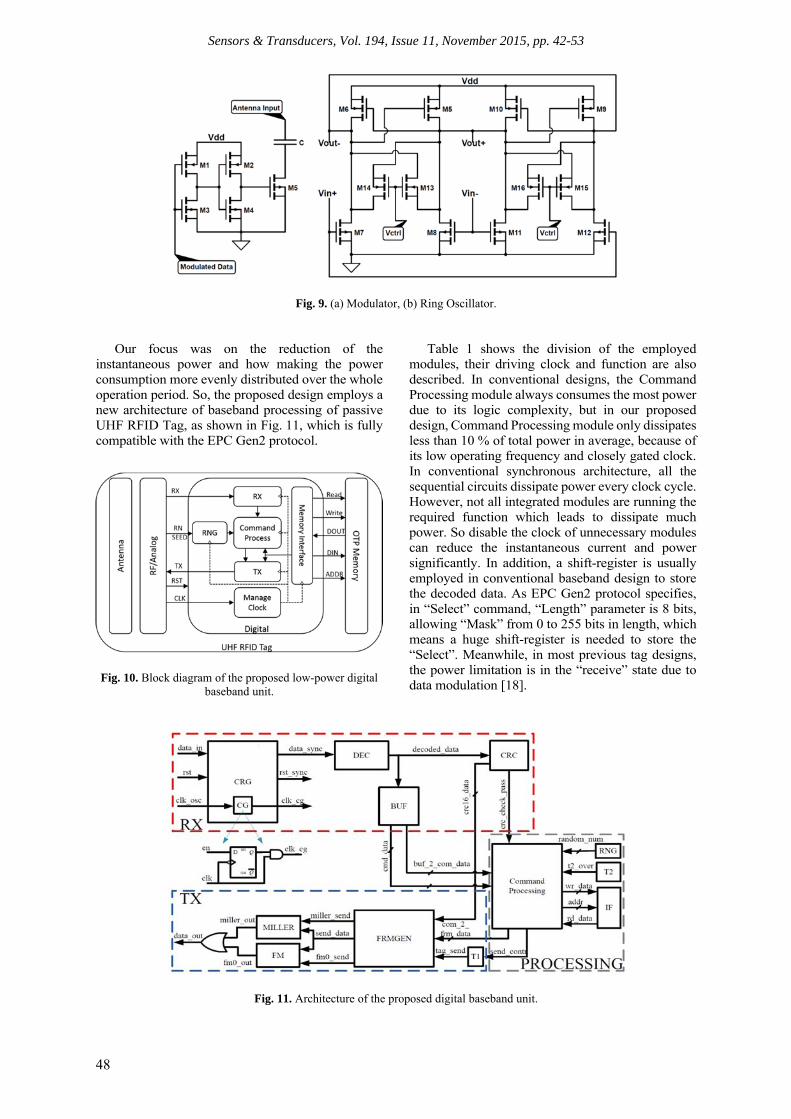
The demodulator converts the Amplitude Shift Keying (ASK) modulated input signal into digital values. A novel sub-1V demodulator is employed, where its architecture consists of one stage Voltage Multiplier (VM), Low-Pass Filter (LPF), and hysteresis comparator. As shown in Fig. 8, the VM identify the envelope of the modulated signal. After the signal pass through the VM, the envelope of incoming data flows to the comparator with hysteresis. On the other hand, the modulator presented in Fig. 9 (a) is realized by a MOS transistor M5 which acts as switch with buffer (M1-M4). By switching on and off this MOS transistor the transponder’s input impedance can be modulated. The modulated signal is called backscatter continues wave. A low-power Voltage Controlled Ring Oscillator (VCRO) is implemented
as a clock generator to avoid the use of a power-hungry one. The generated system clock frequency can vary from 2 to 6 MHz, while theoretically, the minimum clock frequency for robust data decoding is 1.92 MHz in the EPC Gen-2 standard [12]. A low power VCRO capable of functioning as a local oscillator for the tag circuits is achieved by biasing the delay cells to operate in weak inversion region. The design is based on two stage VCRO as shown in Fig. 9(b). The oscillation frequency is fixed by tuning the resistance of transistors M13-M16.
4.2. Digital Baseband Unit
As compared to other non-EPC RFID systems with simple data coding and state management schemes, EPC Gen2 standard features a more robust communication flow with more advanced data encoding, error detection, and anti-collision schemes. To address this challenge, low-power design techniques are employed for the proposed Digital Baseband Unit (DBU) including asynchronous design, clock-gating, low operating frequency, and reuse of registers. Digital section is the baseband processor of the Tag, it performs decoding, CRC checking and calculation, command process, accessing memory, and encoding message back to Reader. Fig. 10 shows the architecture of the digital section inside the passive UHF RFID tag.
Fig. 7. Bandgap reference design.
Fig. 8. Demodulator.
Sensors & Transducers, Vol. 194, Issue 11, November 2015, pp. 42-53
48
Fig. 9. (a) Modulator, (b) Ring Oscillator.
Our focus was on the reduction of the instantaneous power and how making the power consumption more evenly distributed over the whole operation period. So, the proposed design employs a new architecture of baseband processing of passive UHF RFID Tag, as shown in Fig. 11, which is fully compatible with the EPC Gen2 protocol.
Fig. 10. Block diagram of the proposed low-power digital baseband unit.
Table 1 shows the division of the employed modules, their driving clock and function are also described. In conventional designs, the Command Processing module always consumes the most power due to its logic complexity, but in our proposed design, Command Processing module only dissipates less than 10 % of total power in average, because of its low operating frequency and closely gated clock. In conventional synchronous architecture, all the sequential circuits dissipate power every clock cycle. However, not all integrated modules are running the required function which leads to dissipate much power. So disable the clock of unnecessary modules can reduce the instantaneous current and power significantly. In addition, a shift-register is usually employed in conventional baseband design to store the decoded data. As EPC Gen2 protocol specifies, in “Select” command, “Length” parameter is 8 bits, allowing “Mask” from 0 to 255 bits in length, which means a huge shift-register is needed to store the “Select”. Meanwhile, in most previous tag designs, the power limitation is in the “receive” state due to data modulation [18].
Fig. 11. Architecture of the proposed digital baseband unit.

Sensors & Transducers, Vol. 194, Issue 11, November 2015, pp. 42-53
49
Thus, the conventional design scheme will lead to high power requirement and large chip size. In our asynchronous design technique, latch bank is used to replace the shift register. From the study in [19], we can consider that latch dissipates much less power (50 % reduced) and smaller area (40 % reduced) than register and is especially suitable for designing a low-cost low-power passive Tag. The Latch is suitable for storing data which have little change once it was loaded.
Table 1. DBU modules, driving clock, and functions.
Module Clock Function
CRG CLK_OSC Clock/reset generator
DEC CLK_OSC_DEC PIE decoder
CRC CLK_BIT/BLF_CRC CRC check/calculation
BUF CLK_BIT_BUF Command buffer MD-PROCESS
CLK_BLF_CMD Command processing
FRMGEN CLK_BLF_FRMGEN Reply frame generator
IF CLK_BLF_IF Memory interface
RNG CLK_BLF_RNG Random number generator
MILLER CLK_BLF_MILLER Miller encoder FM CLK_BLF_FM FM0 encoder T1 CLK_BLF_T1 T1 time control T2 CLK_BLF_T2 T2 time control
5. Processing Unit
The data received by the RFID receiver is fed to the processing unit for analysis. The possibility of parallel computation in dedicated hardware makes it much faster than the software at run-time. Therefore the processing unit is implemented on heterogeneous reconfigurable Zynq platforms which is having an ARM processor and FPGA chip based on Xilinx 7-series [20]. The reason of selecting the Zynq platform is due to its suitability for hardware/software co-design approach. It is worth noting that the purpose of hardware platform is to process the Dt, whereas the training part is done offline using MATLAB. This is to reduce the hardware overhead caused by the complexity of the feature reduction and classification algorithms. Also, the Dl is used one time for training purpose, so it is more feasible and efficient to do the training offline. Thus, the hardware processing unit is used to perform real-time feature reduction and classification on test data of gases.
5.1. Feature Reduction
The two most common techniques for feature reduction is PCA and LDA both of them have been analyzed in the designed prototype for gas identification so that the best approach can be adopted for final implementation. The aim of feature reduction
is to reduce the feature size without losing useful information. PCA and LDA-based feature reduction algorithms are summarized in Fig. 12.
MeanNormalization
(D1-Mean)Covariance
Matrix
Eigen values and Eigen
Vector Projection
Training Data (D1)
Normalization(D1-Mean)
Testing Data (D2)
Projection
Training
Testing
PCA Based Feature Reduction
(a)
MeanNormalization(TGi-Mean)
Within & Between
Class vVariance
Eigen values and Eigen
Vector Projection
Gas Class(TGi)
Testing Data (D2)
Projection
Training
Testing
LDA Based Feature Reduction
Training Data (D1)
(b)
Fig. 12. Feature reduction algorithm based
on (a) PCA and (b) LDA.
In case of PCA the Eigenvectors (Ev) and mean values will be computed for training data Dl and then the projection of Dl in the new space is obtained by multiplication of normalized data with the Ev using MATLAB. Whereas, since the testing part requires only Eigen vectors and mean values, as shown in Fig. 12 (a) [21], therefore in case of PCA the computed mean and Ev for Dl is pre-stored in the flash memory of the board and at run-time the hardware will take those values to perform normalization and projection of Dt with lower complexity and faster speed.
In contrast to PCA, LDA is not performed directly on Dl because the goal of LDA is to reduce the inter-class differences and simultaneously increase the differences between classes. Therefore, LDA deals with class boundaries which cannot be identified in Dl. Therefore, Dl is split into classes such that data for each gas is considered as a single class. The training-data obtained at different concentrations of gas are stored as a train-class (Tc), where sub-script c is representing the type of gas. After computing normalization as well as between and within class-differences, the Ev will be computed. The Ev is then forwarded to the projection block which projects the Dl on reducing feature space. It is worth noticing that LDA testing part requires only Eigen vectors as shown in Fig. 12 (b) to project Dt on reducing feature space.

Sensors & Transducers, Vol. 194, Issue 11, November 2015, pp. 42-53
50
5.2. Classification
A Binary Decision Tree (BDT) classifier is used to identify the gases with and without the feature reduction. The reason of selecting BDT for classification is because of the simplicity and good performance. The tree formation is carried out on Dl using MATLAB library function, whereas the decision nodes will be implemented in hardware using successive if-else conditions to classify the gases at run-time from the obtained Dt.
6. Implementation Results
The implementation results for processing unit and RFID module presented in this section. Two different sets of gases have been explored, therefore the implementation result for each set is presented in the following sections.
6.1. Gas Set 1 and Set 2 (GS1 and GS2)
The classification of GS1 has been carried out
using BDT and the results has been presented in [22]. The software simulation is carried out using MATLAB whereas the hardware implementation is achieved using Vivado HLS tools [23]. It has been observed that for classification BDT with three principal components can classify 90 % of gases [21] and is therefore 7 % better than using LDA based feature reduction, as shown in Table 2.
However, for hardware implementation LDA based feature reduction requires 50 % less LUTs and 57 % less Flip-Flops (FF) than PCA. Moreover, LDA requires 37.5 % less latency time than PCA, where latency time is the period required to produce the final output, as shown in Table 3.
Table 2. Percent-accuracy results for gas-classification obtained from software simulations.
Gas Set Properties
LDA (%) PCA (%)
2-PCA (%) 3-PCA (%) 4-PCA (%) GS1 83 80 90 90 GS2 Steady State (SS) 91 77 87 91
Table 3. Hardware implementation results for gas-classification.
Gas Set Properties LDA PCA (%)
2-PCA 3-PCA 4-PCA
GS1
FF 893 1656 2089 2089 LUT 1937 3024 3925 3925
Clock Cycles (CC) (Nanoseconds) ns
8.20 8.20 8.20 8.20
Latency Period (CC) 163 263 261 261 Input Interval (CC) 164 264 262 262
GS2
FF 1641 1912 2521 2843 LUT 3406 3968 4882 5227
Clock Cycles (CC) (Nanoseconds) ns
8.20 8.20 8.20 8.22
Latency Period (CC) 165 261 261 266 Input Interval (CC) 166 262 262 267
Furthermore, the BDT obtained with LDA based feature reduction algorithm exhibits only 2 decision nodes along with unity depth, while in case of PCA the BDT have 4-decision nodes with three steps in depth. Therefore, LDA offers simplified decision tree which requires less time for searching and classification of gas than PCA, as shown in Fig. 13.
For GS2, the BDT is shown in Fig. 14, it is observed that for the given data, classification obtained after LDA is equal to the classification obtained using the first four principal components (4-PCA) and is equal to 91 % as shown in Table 2. However, in terms of the hardware overhead LDA requires 73 % less FF than 4-PCA, whereas the required LUT for LDA is also 53 % less than 4-PCA as shown in Table 2.
Similar to GS1, the BDT after LDA based feature
reduction, with only 5 decision nodes, requires less complexity than 4-PCA. Moreover, only 5 tree leaves is required after LDA based feature reduction, whereas 9 tree leaves are required after PCA based feature reduction.
6.2. RFID Module
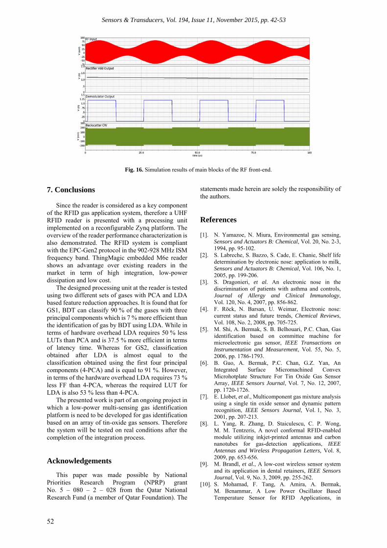
Fig. 15 shows the details of the adopted low-
power clock strategy when Tag receives a Read command. From these figures, we can conclude that the CRG module is dominant in the power dissipation, while the Command Processing module is negligible compared to the total power consumption of the tag since its running time only lasts several clock cycles.

Sensors & Transducers, Vol. 194, Issue 11, November 2015, pp. 42-53
51
The proposed UHF RFID tag is implemented and simulated in 0.13 μm CMOS process. The circuit is powered up in 60 μs which satisfies the specification of the EPC Gen-2 standard. The design supports carrier frequency within the 902-928 MHz ISM band with forward and return link data rate up to 200 kbps. The frequency of clock is 2.47 MHz at the control voltage of 1.2 V.
Fig. 16 is the post layout results of the ASK demodulation, rectifier and modulation waveforms the minimum input RF signal that can be demodulated is -17 dBm with an input data rate of 40 kb/s. The modulation index of the RF signal is 90%. The modulated signal from the tag is carried on the continuous wave reader signal.
COC2H6OCO
COH2
3 PCAs
x3 < 0.135 x3 ≥ 0.135
x1 < 4.314 x1 ≥ 4.314x2 < 0.177 x2 ≥ 0.177
x1 < 3.634 x1 ≥ 3.634
(a)
(b)
Fig. 13. BDT for GS1: (a) 3-PCA, and (b) LDA.
SO2NO2CO
C6H6
LDA
x2 < 0.229 x2 ≥ 0.229
x1 < -4.441 x1 ≥ -4.441x1 < -2.829 x1 ≥ -2.829
x2 < 0.1667 x2 ≥ 0.1667
C6H6CH2O
x1 < -4.45 x1 ≥ -4.45
(a)
SO2
NO2
CO
C6H6
4-PCA
x2 < 0.144 x2 ≥ 0.144
x4 < 0.004 x4 ≥ 0.004x1 < -0.8128 x1 ≥ -0.8128
x3 < -0.269 x3 ≥ -0.269
C6H6 CH2O
x4 < -0.324 x4 ≥ -0.324
NO2
SO2
x3 < 0.5802 x3 ≥ 0.5802
x1 < 0.603 x1 ≥ 0.603
(b)
Fig. 14. BDT for GS2: (a) 4-PCA and (b) LDA.
Fig. 15. Low-power clock strategy.
Sensors & Transducers, Vol. 194, Issue 11, November 2015, pp. 42-53
52
Fig. 16. Simulation results of main blocks of the RF front-end.
7. Conclusions Since the reader is considered as a key component
of the RFID gas application system, therefore a UHF RFID reader is presented with a processing unit implemented on a reconfigurable Zynq platform. The overview of the reader performance characterization is also demonstrated. The RFID system is compliant with the EPC-Gen2 protocol in the 902-928 MHz ISM frequency band. ThingMagic embedded M6e reader shows an advantage over existing readers in the market in term of high integration, low-power dissipation and low cost.
The designed processing unit at the reader is tested using two different sets of gases with PCA and LDA based feature reduction approaches. It is found that for GS1, BDT can classify 90 % of the gases with three principal components which is 7 % more efficient than the identification of gas by BDT using LDA. While in terms of hardware overhead LDA requires 50 % less LUTs than PCA and is 37.5 % more efficient in terms of latency time. Whereas for GS2, classification obtained after LDA is almost equal to the classification obtained using the first four principal components (4-PCA) and is equal to 91 %. However, in terms of the hardware overhead LDA requires 73 % less FF than 4-PCA, whereas the required LUT for LDA is also 53 % less than 4-PCA.
The presented work is part of an ongoing project in which a low-power multi-sensing gas identification platform is need to be developed for gas identification based on an array of tin-oxide gas sensors. Therefore the system will be tested on real conditions after the completion of the integration process.
Acknowledgements
This paper was made possible by National Priorities Research Program (NPRP) grant No. 5 – 080 – 2 – 028 from the Qatar National Research Fund (a member of Qatar Foundation). The
statements made herein are solely the responsibility of the authors.
References [1]. N. Yamazoe, N. Miura, Environmental gas sensing,
Sensors and Actuators B: Chemical, Vol. 20, No. 2-3, 1994, pp. 95-102.
[2]. S. Labreche, S. Bazzo, S. Cade, E. Chanie, Shelf life determination by electronic nose: application to milk, Sensors and Actuators B: Chemical, Vol. 106, No. 1, 2005, pp. 199-206.
[3]. S. Dragonieri, et al. An electronic nose in the discrimination of patients with asthma and controls, Journal of Allergy and Clinical Immunology, Vol. 120, No. 4, 2007, pp. 856-862.
[4]. F. Röck, N. Barsan, U. Weimar, Electronic nose: current status and future trends, Chemical Reviews, Vol. 108, No. 2, 2008, pp. 705-725.
[5]. M. Shi, A. Bermak, S. B. Belhouari, P.C. Chan, Gas identification based on committee machine for microelectronic gas sensor, IEEE Transactions on Instrumentation and Measurement, Vol. 55, No. 5, 2006, pp. 1786-1793.
[6]. B. Guo, A. Bermak, P.C. Chan, G.Z. Yan, An Integrated Surface Micromachined Convex Microhotplate Structure For Tin Oxide Gas Sensor Array, IEEE Sensors Journal, Vol. 7, No. 12, 2007, pp. 1720-1726.
[7]. E. Llobet, et al., Multicomponent gas mixture analysis using a single tin oxide sensor and dynamic pattern recognition, IEEE Sensors Journal, Vol. 1, No. 3, 2001, pp. 207-213.
[8]. L. Yang, R. Zhang, D. Staiculescu, C. P. Wong, M. M. Tentzeris, A novel conformal RFID-enabled module utilizing inkjet-printed antennas and carbon nanotubes for gas-detection applications, IEEE Antennas and Wireless Propagation Letters, Vol. 8, 2009, pp. 653-656.
[9]. M. Brandl, et al., A low-cost wireless sensor system and its application in dental retainers, IEEE Sensors Journal, Vol. 9, No. 3, 2009, pp. 255-262.
[10]. S. Mohamad, F. Tang, A. Amira, A. Bermak, M. Benammar, A Low Power Oscillator Based Temperature Sensor for RFID Applications, in

Sensors & Transducers, Vol. 194, Issue 11, November 2015, pp. 42-53
53
Proceedings of the 5th Asia Symposium on Quality Electronic Design (ASQED), 2013, pp. 50-54.
[11]. R. Weinstein, RFID: A Technical Overview and it’s Application to the Enterprise, IT Professional, Vol. 7, No. 3, 2005, pp. 27-33.
[12]. EPCglobal Inc., EPC Radio-Frequency Identity Protocols Class-1 Generation-2 UHF RFID Protocol for Communications at 860 MHz-960 MHz Version 1.0.9, EPC Global Standards, 2005.
[13]. K. Finkenzeller, RFID Handbook, John Wiley & Sons, New York, 2003.
[14]. A. S. Ahson, M. Ilyas, RFID Handbook: Applications, Technology, Security and Privacy, CRC Press, 2008.
[15]. P. Nikitin, K. V. S. Rao, S. Lam, UHF RFID tag characterization: overview and state-of-the-art, in Proceedings of the 34th Annual Meeting and Symposium on Antenna Measurement Techniques Association Symposium (AMTA), 2012, pp. 289-294.
[16]. M. Zgaren, M. Sawan, A Front end-EPC Gen-2 Passive UHF RFID Transponder for Embedded Gas Sensor, in Proceedings of the 4th International Gas Processing Symposium, 2014, pp. 223-231.
[17]. ‘M6e High-Performance 4-Port UHF RFID Module’, http://www.dpie.com/manuals/rfid/M6eHardwareGuide_Sept13.pdf, v 1.13.1, accessed May 12, 2015.
[18]. Y. Ling, et al., System Level Power Optimizations For EPC RFID Tags to Improve Sensitivity Using Load Power Shaping and Operation Scheduling, in Proceedings of the IEEE International Symposium on Circuits and Systems (ISCAS), 2010, pp. 3012-3015.
[19]. D. Wei, C. Zhang, Y. Cui, H. Chen, Z. Wang, Design of a low-cost low-power baseband-processor for UHF RFID tag with asynchronous design technique, in Proceedings of the IEEE ISCAS, May 2012, pp. 2789-2792.
[20]. Inc Xilinx. Zynq-7000 All Prog. SoC: Tech. Reference Manual, http://www.xilinx.com/support/documentati on/user_guides/ug585-Zynq-7000-TRM.pdf, UG585, v1.8.1, accessed Feb. 20, 2015.
[21]. A. Ait Si Ali, A. Amira, F. Bensaali, M. Benammar, Hardware PCA for Gas Identification Systems Using High Level Synthesis on the Zynq SoC, in Proceedings of the IEEE 20th International Conference on Electronics, Circuits, and Systems (ICECS), 2013, pp. 707-710.
[22]. M. A. Akbar, A. Ait Si Ali, A. Amira, F. Bensaali, M. Benammar, M. Zgaren, M. Sawan, A. Bermak, Receiver Design of Passive UHF RFID Sensor Platform for Gas Identification, in Proceedings of the 6th International Conference on Sensor Device and Technologies (SENSORDEVICES’ 2015), Venice, Italy, 23-28 August 2015, pp. 164-169.
[23]. ‘Inc Xilinx Vivado Design Suite User Guide: Embedded Processor H/W Design’, http://www.xilinx.com/support/documentation/sw_manuals/xilinx2013_3/ug898-vivado-embedded-design.pdf, UG898, v2014.3, accessed March 9, 2015
.
___________________
2015 Copyright ©, International Frequency Sensor Association (IFSA) Publishing, S. L. All rights reserved. (http://www.sensorsportal.com)


![Reading of UHF band passive RFID tags using a reflectorap-s.ei.tuat.ac.jp/isapx/2011/pdf/[FrD4-5] A14_1005.pdfReading of UHF band passive RFID tags using a reflector #Yuki Oowashi](https://img.dokumen.tips/doc/110x75/5fe5f65925c7f35d9b27fe6b/reading-of-uhf-band-passive-rfid-tags-using-a-reflectorap-seituatacjpisapx2011pdffrd4-5.jpg)