Embed Size (px)
Citation preview

Galiuro Drilling Project Plan of Operations
Kennecott Exploration Company
Water, Soil and Air Resources Report
Prepared by: Gregory S. Olsen Hydrogeologist
Coronado and Tonto National Forests
for: Safford Ranger District
Coronado National Forest
Revised December 8, 2017

2
In accordance with Federal civil rights law and U.S. Department of Agriculture (USDA) civil rights regulations and policies, the USDA, its Agencies, offices, and employees, and institutions participating in or administering USDA programs are prohibited from discriminating based on race, color, national origin, religion, sex, gender identity (including gender expression), sexual orientation, disability, age, marital status, family/parental status, income derived from a public assistance program, political beliefs, or reprisal or retaliation for prior civil rights activity, in any program or activity conducted or funded by USDA (not all bases apply to all programs). Remedies and complaint filing deadlines vary by program or incident.
Persons with disabilities who require alternative means of communication for program information (e.g., Braille, large print, audiotape, American Sign Language, etc.) should contact the responsible Agency or USDA’s TARGET Center at (202) 720-2600 (voice and TTY) or contact USDA through the Federal Relay Service at (800) 877-8339. Additionally, program information may be made available in languages other than English.
To file a program discrimination complaint, complete the USDA Program Discrimination Complaint Form, AD-3027, found online at http://www.ascr.usda.gov/complaint_filing_cust.html and at any USDA office or write a letter addressed to USDA and provide in the letter all of the information requested in the form. To request a copy of the complaint form, call (866) 632-9992. Submit your completed form or letter to USDA by: (1) mail: U.S. Department of Agriculture, Office of the Assistant Secretary for Civil Rights, 1400 Independence Avenue, SW, Washington, D.C. 20250-9410; (2) fax: (202) 690-7442; or (3) email: [email protected] .

3
Contents Figures ........................................................................................................................................................... 5
List of Acronyms ............................................................................................................................................ 6
1 Introduction ........................................................................................................................................ 10
2 Relevant Laws, Regulations, and Policy .............................................................................................. 10
2.1 Regulatory Framework – Water Resources ................................................................................ 11
2.2 Regulatory Framework – Air Resources ...................................................................................... 12
3 Forest Service Management Direction ............................................................................................... 12
3.1 Water Resources – Forest Service Policy and Guidance ............................................................. 12
3.2 Air Resources – Forest Service Policy and Guidance .................................................................. 13
3.3 Land and Resource Management Plan ....................................................................................... 14
4 Issues Addressed in this Environmental Analysis ............................................................................... 15
4.1 Issues Scoping ............................................................................................................................. 15
4.2 Concise List of Causes and Effects to Analyze ............................................................................. 16
5 Environmental Analysis Methodologies ............................................................................................. 17
5.1 Information Sources .................................................................................................................... 18
5.2 Incomplete and Unavailable Information ................................................................................... 18
5.3 Assumptions ................................................................................................................................ 19
5.4 Spatial and Temporal Context for Effects Analysis ..................................................................... 19
6 Proposed Action .................................................................................................................................. 20
6.1 Project Location .......................................................................................................................... 20
6.2 Boring Locations and Depths ...................................................................................................... 20
6.3 Site Access ................................................................................................................................... 21
6.4 Drilling Methods.......................................................................................................................... 21
6.4.1 Equipment ........................................................................................................................... 22
6.4.2 Sumps and Cuttings............................................................................................................. 23
6.4.3 Supplies and Materials ........................................................................................................ 24
6.4.4 Water Supply ....................................................................................................................... 24
6.4.5 Borehole Testing and Data Collection ................................................................................. 25
6.4.6 Artesian Conditions ............................................................................................................. 25
6.4.7 Borehole Abandonment ...................................................................................................... 26
6.5 Site Reclamation ......................................................................................................................... 26

4
6.6 Timeframe and Work Schedule .................................................................................................. 27
7 Alternatives Development .................................................................................................................. 27
7.1 Mitigation Measure WR-1 – Borehole Abandonment Methods and Specifications .................. 28
7.2 Mitigation Measure WR/SR-2 – Control of Artesian Flows ........................................................ 29
7.3 Mitigation Measure WR/SR-3 – Drilling Fluid Gain - Permits under the CWA De Minimis General Permit (DMGP) .......................................................................................................................... 30
7.4 Mitigation Measure WR-4 – Disinfection of Drilling Water Supply ............................................ 31
7.5 Mitigation Measure WR-5 – Prevention of Backflow to Private Property (Well) ....................... 33
7.6 Mitigation Measure WR/SR-6 – Disposal of drill cuttings, liquid and solid wastes .................... 35
7.7 Mitigation Measure WR-7 - Monitoring, Reporting and Agreement on Hydrogeologic Data Sharing .................................................................................................................................................... 37
7.8 Mitigation Measure WR/SR-8 – Permits under the CWA Construction General Permit (CGP) or Multi Sector General Permit (MSGP) ...................................................................................................... 38
7.9 Mitigation Measure AR-9 – Dust Abatement ............................................................................. 40
7.10 Mitigation Measure AR-10 – Engine Emissions .......................................................................... 41
7.11 Mitigation Measure SR/WR-11 – Water Supply Pipeline Leakage Detection ............................. 42
8 Affected Environment ......................................................................................................................... 43
8.1 Climate ........................................................................................................................................ 43
8.2 Physiographic Setting .................................................................................................................. 45
8.3 General Area Topography ........................................................................................................... 45
8.4 Geologic Setting .......................................................................................................................... 48
8.5 Hydrologic Setting ....................................................................................................................... 49
8.5.1 Conceptual Hydrologic Model............................................................................................. 49
8.5.2 Groundwater ....................................................................................................................... 51
8.5.3 Surface Water ..................................................................................................................... 54
8.5.4 Municipal Watersheds ........................................................................................................ 56
8.5.5 Streams - Flow Regimes, Designated Use, and Unique Waters .......................................... 56
8.5.6 Springs ................................................................................................................................. 56
8.5.7 Surface Water Quality ......................................................................................................... 57
8.5.8 Wetlands ............................................................................................................................. 62
8.5.9 Riparian Habitat .................................................................................................................. 62
8.5.10 Floodplains .......................................................................................................................... 63
8.6 Soil ............................................................................................................................................... 66
8.7 Air ................................................................................................................................................ 67

5
9 Environmental Consequences ............................................................................................................ 71
9.1 Alternative 1 - No Action ............................................................................................................. 71
9.1.1 Effects of the No Action Alternative - Water, Soil and Air Resources ................................ 71
9.2 Alternative 2 - Proposed Action .................................................................................................. 71
9.2.1 Effects of the Proposed Action - Water Resources ............................................................. 71
9.2.2 Cumulative Effects to Water Resources ............................................................................. 75
9.2.3 Effects of the Proposed Action - Soil Resources ................................................................. 76
9.2.4 Cumulative Effects to Soil Resources .................................................................................. 77
9.2.5 Effects of the Proposed Action - Air Resources .................................................................. 77
9.2.6 Cumulative Effects to Air Resources ................................................................................... 79
10 References ...................................................................................................................................... 80
11 Glossary ........................................................................................................................................... 84
Appendix A
Appendix B
Appendix C
Figures Figure 1- Annual Average Wind Rose Plot for Safford Municipal Airport................................................... 45 Figure 2- Area Topography, Watersheds and Proposed Drill Sites ............................................................. 47 Figure 3 - Geology - USGS (Drewes, H., 1996) ............................................................................................ 49 Figure 4 - Cursory Fracture Trace and Lineament Analysis of the Norton Springs / Drill Site Gal01P area 53 Figure 5 - Area Watersheds based on Hydrologic Unit Code (HUC 6th code). KEC Proposed drill sites are shown. ......................................................................................................................................................... 55 Figure 6 - Spring Box at Norton Spring (8/17/16) ....................................................................................... 57 Figure 7 - ADEQ Sample Sites and Impaired Streams in the Project Vicinity (ADEQ, 2016) Note Impaired reach of Copper Canyon depicted in red, and ADEQ samples sites, all located downstream of NFS Lands. .................................................................................................................................................................... 58 Figure 8 - Norton Spring (approx. 50 feet below the spring box, in streambed of Scanlon Wash 8/17/16) .................................................................................................................................................................... 59 Figure 9 - Trilinear diagram of general water quality parameters - Norton Spring sampled 8/17/16 ....... 61 Figure 10 - Scanlon Wash below Norton Spring (8/17/16) ......................................................................... 62 Figure 11- Project Area Streams, 300 Foot Stream Buffers, Drill Site Locations, and Forest Boundary. Location of the August 17, 2016 site visit to Norton Spring is also shown. This map is not a floodplain map. This map was used to determine what of the 12 proposed drill sites are within 300’ of an NHD stream. ........................................................................................................................................................ 65

6
Figure 12- Drill pad Gal01P (Photo from KEC PoO). Note that the area shown here is located on a high terrace above Scanlon wash. No visible indicators of modern flooding were observed on this terrace. Norton Spring and Scanlon Wash are approximately 100 feet from this foreground location. ................. 66 Figure 13- Map of Air Quality Non-Attainment Areas (ADEQ). The Galiuro Wilderness is a Federal Class I airshed. ....................................................................................................................................................... 68 Figure 14– USFS Wilderness Visibility Monitoring Station and View Direction - Galiuro Wilderness – The monitoring station was active from approximately 1985 – 1992 https://www.fsvisimages.com/gallery/GALI/html/project/SPECmap_only.PDF ....................................... 69 Figure 15– Historic Visibility Monitoring - Galiuro Wilderness - 10/15/91 @ 1500 Hours - Winter Pristine Conditions (https://www.fsvisimages.com/gallery/GALI/Html/IMG0024.htm) ........................................ 70 Figure 16– Historic Visibility Monitoring - Galiuro Wilderness - 6/4/90 @ 1500 hours - Haze Event (https://www.fsvisimages.com/gallery/GALI/Html/IMG0040.htm) .......................................................... 70
List of Acronyms µg/l - micrograms/liter
A&Wc - Aquatic & Wildlife coldwater
A&Ww - Aquatic & Wildlife warmwater
ABA - Acid Base Accounting
AAC - Arizona Administrative Code
ac-ft - acre-feet
ADEQ - Arizona Department of Environmental Quality
ADWR - Arizona Department of Water Resources
AgL - Agricultural Livestock
AMA - Active Management Areas
APP - Aquifer Protection Permit
AR - Air Resources
ARD - Acid Rock Drainage
ARS - Arizona Revised Statutes
Au - Gold
AWQS - Aquifer Water Quality Standards
AZPDES - Arizona Pollutant Discharge Elimination System
BLM - Bureau of Land Management

7
BMP - Best Management Practices
CAA - Clean Air Act
CERCLA - Comprehensive Environmental Response, Compensation, and Liability Act
CGP - Construction General Permit
CH4 - Methane
CNF - Coronado National Forest
CO - Carbon Monoxide
Cu - Copper
CWA - Clean Water Act
DF - Design Features
DMGP - De Minimis General Permit
DWS - Drinking Water Standards
EA - Environmental Assessment
EPA - United States Environmental Protection Agency
FBC - Full Body Contact
FC - Fish Consumption
FEMA - Federal Emergency Management Agency
FP - Forest Plan
FSH - Forest Service Handbook
FSM - Forest Service Manual
FWPCA - Federal Water Pollution Control Act
Gal - Gallons
GIS - Geographic Information System
GTES - General Terrestrial Ecosystem Survey
GTES - General Terrestrial Ecosystem Survey
HAP - Hazardous Air Pollutants
HP - Horsepower
HUC - Hydrologic Unit Code
IDT - Inter-Disciplinary Team

8
KEC - Kennecott Exploration Company
LRMP - Land and Resource Management Plan
LZ – Landing Zones (helicopter)
MCL - Maximum Contaminant Level
mg/l - milligrams/liter
MM - Mitigation Measures
MM - Mitigation Measures
Mo - Molybdenum
MSGP - Multi-Sector General Permit
NAAQS - National Ambient Air Quality Standards
NEPA - National Environmental Policy Act
NESHAP - National Emission Standards for Hazardous Air Pollutants
NFS - National Forest System
NHD - National Hydrology Database
NOAA - National Oceanic and Atmospheric Administration
NOI - Notice of Intent
NOx - nitrogen oxides
NPDES - National Pollutant Discharge Elimination System
NPS - Non Point Source
O&M - Operations and Maintenance
O3 – Ozone
PA - Proposed Action
Pb - Lead
PM10 - Particulate Matter 10 µm
PM2.5 - Particulate Matter 2.5 µm
PoO - Plan of Operations
PPEPM - Proponent Proposed Environmental Protection Measures
PSD - Prevention of Significant Deterioration
RCRA - Resource Conservation and Recovery Act

9
RD - Ranger District
RMap – Riparian Map (USFS Region 3 Riparian Geospatial Data Set)
RPM - Revolutions per Minute
SDS - Safety Data Sheets
SDWA - Safe Drinking Water Act
SO2 - Sulfur Dioxide
SOP – Standard Operating Procedures
SPLP - Synthetic Precipitation Leach Procedure
SR - Soil Resources
SRP - Spill Response Plan
SWPPP - Storm Water Pollutant Prevention Plan
SWQS - Surface Water Quality Standards
TCLP - Toxicity Characteristic Leach Procedure
TEUI - Terrestrial Ecosystem Unit Inventory
U.S.C. - United States Code
ULSD - Ultra-Low Sulfur Diesel
USC - University of Southern California (Foundation for Cross-Connection Control and Hydraulic Research)
USDA - United States Department of Agriculture
USDOI - United States Department of the Interior
USFS - United States Forest Service
USFWS - United States Fish and Wildlife Service
USGS - United States Geological Survey
UV - Ultra Violet
VOC - Volatile Organic Compounds
WR - Water Resources
WRCC - Western Regional Climate Center

10
1 Introduction The emphasis of this specialist report is an environmental analysis of the proposed actions identified within the Galiuro Drilling Project, Plan of Operations (PoO) submitted by the Kennecott Exploration Company (KEC), revised 2/26/2016, (KEC, 2016a; KEC 2016b) and the predicted and/or potential effects associated with Water, Soils and Air resources. The official version of the Purpose and Need as well as the Proposed Action (PA) can be found in the Environmental Assessment (EA) document for this project.
Briefly, the project is a mineral exploration drilling program called the Galiuro Drilling Project, The PoO calls for up to 12 diamond core borings to depths of up to 5000 feet, or more. The primary purpose of the Galiuro project is to conduct early stage Copper-Gold-Molybdenum and associated base and precious metals mineral exploration, (KEC, 2016a). Access across NFS lands to the drill sites, is proposed to be predominantly by helicopter. The project is to be completed in a five-year timeframe.
2 Relevant Laws, Regulations, and Policy Federal, State and Local laws and their implementing regulation that may apply to the proposed action include, but are not limited to, the following:
Federal
• National Environmental Policy Act (NEPA) of 1969, as amended • National Forest Management Act • 1872 Mining Law, as amended • 36 CFR 228, Surface Management Regulations • Federal Water Pollution Control Act, as amended by the Clean Water Act (CWA) of 1977 • Safe Drinking Water Act (SDWA), as amended • Clean Air Act (CAA) • Resource Conservation and Recovery Act (RCRA) of 1986 • Comprehensive Environmental Response, Compensation, and Liability Act (CERCLA) of 1980, as
amended • Executive Order 11988 (Floodplain Management) • Executive Order 11990 (Protection of Wetlands)
State
• Arizona Revised Statutes (ARS) • Arizona Administrative Code (AAC) • Arizona Department of Environmental Quality (ADEQ) • Arizona Department of Water Resources (ADWR)
County
• Graham County Ordinances

11
2.1 Regulatory Framework – Water Resources Federal - Clean Water Act
The regulatory framework for surface water resources is established by the Clean Water Act (CWA) and ARS Title 49. The CWA (33 United States Code [U.S.C.] Section 1250 et seq.) is the foundation for surface water quality protection. The objective of the CWA is to restore and maintain the chemical, physical, and biological integrity of domestic waters (i.e., waters of the U.S.). The CWA provides that states may receive delegated authority for controlling point and non-point source water pollution, designating uses for surface water bodies within state boundaries, and adopting water quality standards to protect those designated uses. Section 402 of the CWA established the National Pollutant Discharge Elimination System (NPDES) program, which prohibits point source discharge of pollutants to waters of the U.S. unless authorized by an NPDES permit. Effective December 2002, the U.S. Environmental Protection Agency (EPA) delegated implementation of the Federal NPDES program to the state of Arizona and is referred to as the Arizona Pollutant Discharge Elimination System (AZPDES).
The ADEQ administers both individual and general AZPDES in accordance with ARS Title 49-255. The general permit known as the Arizona Construction General Permit (CGP) authorizes storm water discharges for multiple types of facilities without requiring site-specific applications for individual AZPDES permits. In general, land disturbances totaling one acre or more (including equipment and material staging areas) will require a CGP. In order to obtain coverage under the CGP, an operator must submit a Notice of Intent and prepare a site-specific Storm Water Pollutant Prevention Plan (SWPPP).
Federal – Executive Orders
There are two Executive Orders related to water resources and this project: Executive Order
11988 (Floodplain Management), and Executive Order 11990 (Protection of Wetlands).
State of Arizona – Groundwater Regulations
Groundwater quality is regulated by the state of Arizona thru the ADEQ. ADEQ regulates and manages groundwater quality, primarily through the Aquifer Protection Permit (APP) program, and also establishes Aquifer Water Quality Standards (AWQS) for the States ground waters.
Groundwater quantity and uses are regulated by the state of Arizona thru the Arizona Department of Water Resources (ADWR). The ADWR regulates and manages groundwater quantity to ensure a long-term, sufficient, and secure water supply. Under ARS Title 45, portions of the state have been designated “Active Management Areas” (AMA) for groundwater. The project area is not located in a located in an AMA, thus no further discussion of AMAs will occur in this report.
The state of Arizona ADWR also regulates well construction under AAC Title 12, Chapter 15, Article 8. These regulations outline minimum construction standards for wells/borings and specify methods for abandonment.

12
2.2 Regulatory Framework – Air Resources Federal - Clean Air Act
The basic framework for controlling air pollutants in the United States is mandated by the 1970 Clean Air Act (CAA), as amended in 1977 and 1990. The CAA was designed to “protect and enhance” air quality. Section 160 of the CAA requires measures “to preserve, protect, and enhance the air quality in national parks, national wilderness areas, national monuments, national seashores, and other areas of special national or regional natural, recreation, scenic, or historic value.” Stringent requirements are therefore established for areas designated as “Class I” areas. Class I areas include Forest Service and Fish and Wildlife Service wilderness areas over 5,000 acres that were in existence before August 1977 and National Parks in excess of 6,000 acres as of August 1977. Designation as a Class I area allows only very small increments of new pollution above already existing air pollution levels. http://www.fs.fed.us/air/documents/Smoke%20NEPA_2005_Nov.pdf
State of Arizona - Air Quality
Air quality regulations implemented by ADEQ include provisions applicable to construction projects which are considered “temporary sources.” A temporary source is defined in the AAC, Title 18, Chapter 2, Article 1, Section 101 (R18-2-101), as a source that is portable and does not qualify as an affected source under the acid deposition rules of the Clean Air Act. It should be noted that items of equipment (specifically generators and equipment engines) used during construction activities are not subject to State permitting.
3 Forest Service Management Direction 3.1 Water Resources – Forest Service Policy and Guidance Forest Service Manual [FSM] 2500 - WATERSHED AND AIR MANAGEMENT - SOUTHWESTERN REGION (REGION 3)
CHAPTER 2530 – WATER RESOURCE MANAGEMENT
Supplement No.: 2500-92-1
2532 - WATER QUALITY MANAGEMENT
The Federal Water Pollution Control Act of 1948 was the first major U.S. law to address water pollution. In 1972, the Federal Water Pollution Control Act (FWPCA) Amendments became law. The Clean Water Act (CWA) of 1977 amended the original document with further modifications occurring in the Reauthorization Act of 1987. Together, these documents provide the authority to manage water quality on National Forest Service (NFS) lands.
Section 319 of the amended CWA provides authority for each state to prepare a nonpoint source (NPS) water quality management program that includes cooperation with Federal agencies. As part of that cooperation the states have recognized the Forest Service as a designated management agency for NPS water quality management. They have recognized USFS Integrated Resource Management process for developing Best Management Practices (BMPs) to control NPS water pollution on NFS lands.

13
12.1 2532.02 - Objective.
To control NPS water pollution through the application of BMPs.
12.2 2532.03 - Policy.
BMPs will be developed within the guidelines and procedures set forth in R-3 Forest Service Handbook [FSH] 2509.22, "Soil and Water Conservation Practices Handbook."
Floodplain Management Directives
FSM 2527.03
• Avoid adverse impacts that may be associated with the occupancy and modification of floodplains and with the destruction, loss, or degradation of wetlands. Avoid filling of land within floodplains and wetlands wherever practicable.
• Do not permit floodplain development and new construction in wetlands wherever there is a practicable alternative.
3.2 Air Resources – Forest Service Policy and Guidance FSM 2500 – WATERSHED AND AIR MANAGEMENT - SOUTHWESTERN REGION (REGION 3)
CHAPTER 2580 – AIR RESOURCE MANAGEMENT
Supplement No.: 2500-2005-1
12.1 2580.1- Authority
12.2
The Environmental Protection Agency (EPA) is directed to implement the Clean Air Act (CAA), Public Law 101-549 as amended, through EPA-approved State Implementation Plans (SIPs) or through Federal Implementation Plans (FIPs) in the absence of an approved SIP… In Arizona, the Air Quality Rules are adopted and implemented through the Department of Environmental Quality… State and local air quality regulations that affect certain management activities in the Southwestern Region include: Arizona Air Pollution Rules (ARS 49.501; Title 18, Environmental Quality, Chapter 2, Air Pollution Control)
12.3 2580.3 - Policy
Air is a basic National Forest System resource to be protected. In the management of this resource the Region shall cooperate with other Federal, state and local regulatory agencies, as well as the public and private land managers to:
1. Minimize the impact of the Region's management activities on air quality and comply with requirements of Federal, state and local air regulatory authorities.

14
2. Affirmatively protect Air Quality Related Values (AQRV) within the Region's Class I wilderness areas (2580.5 - Exhibit 01).
3. Protect Resource Values Affected by Air Pollution (RVAAP) on all National Forest System Lands.
4. Maintain or improve air quality within Class I airsheds (2580.5 - Exhibit 02.)
The Galiuro Wilderness is identified as a Class I Airshed in 2580.5 - Exhibit 01.
3.3 Land and Resource Management Plan The Coronado National Forest (CNF) - Land and Resource Management Plan (LRMP) provides standards and guidelines for water, soil and air resources. (USDA USFS CNF, 1986, as amended). The project area is predominantly within CNF Management Area 1, with exception of drilling site Gal02P which is in Management Area 4.
Water Resources
The Forest Plan (FP) establishes practices and guidelines for the long-term management of National Forest System lands. Protection of groundwater and surface water resources for this project would be achieved by following the Forest Plan guidance including the USFS BMPs. Several Forest-Wide Management Prescriptions have been established for water resources, including guidelines to minimize effects on water resources from drilling exploration projects, ground-disturbing activities, improve watershed conditions, and avoid disturbance of stream channels to minimize effects on riparian vegetation (USDA USFS CNF, 1986, as amended).
• Monitor designated projects according to an approved water quality monitoring plan. (USDA USFS CNF, 1986, FP p38)
• Manage riparian areas in accordance with legal requirements regarding flood plains, wetlands, wild and scenic rivers, and cultural and other resources. Recognize the importance and distinct values of riparian areas in Forest Plans. (USDA USFS CNF, 1986, FP p39)
• Manage riparian areas to protect the productivity and diversity of riparian-dependent resources by requiring actions within or affecting riparian areas to protect and, where applicable, improve dependent resources (FSM 2526). Emphasize protection of soil, water, vegetation, and wildlife and fish resources prior to implementing projects (FSM 2526). (USDA USFS CNF, 1986, FP p39)
• Give preferential consideration to resources dependent on riparian areas over other resources. Other resource uses and activities may occur to the extent that they support or do not adversely affect riparian-dependent resources. (USDA USFS CNF, 1986, FP p39)
• Manage all programs to eliminate or minimize onsite and downstream water pollution. (CNF, 1986, FP p65).
Soil Resources
Soil and watershed resources would be managed using Forest Plan standards for soils and erosion including the following Forest-Wide Management Prescriptions that are applicable to the project:

15
• Management of forest resources to protect or enhance watershed condition from both a hydrologic function and soil productivity standpoint.
• Mitigate any adverse effects of planned activities on soil and water resources through the use of Applicant-proposed BMPs and Forest BMPs and Mitigation Measures
• Through management services, provide information to minimize disturbance and improve already disturbed areas. Best management practices will be used to minimize the time of recovery to a satisfactory erosion level, minimize soil productivity loss, improve water quality and minimize channel damage. (USDA USFS CNF, 1986, p38)
• Restrict equipment use to terrain and climatic conditions where soil damage will be minimal. (USDA USFS CNF, 1986, FP p39)
• Manage riparian areas in accordance with legal requirements regarding flood plains, wetlands, wild and scenic rivers, and cultural and other resources. Recognize the importance and distinct values of riparian areas in Forest Plans. (USDA USFS CNF, 1986, FP p39)
• Manage riparian areas to protect the productivity and diversity of riparian-dependent resources by requiring actions within or affecting riparian areas to protect and, where applicable, improve dependent resources (FSM 2526). Emphasize protection of soil, water, vegetation, and wildlife and fish resources prior to implementing projects (FSM 2526). (USDA USFS CNF, 1986, FP p39)
• Give preferential consideration to resources dependent on riparian areas over other resources. Other resource uses and activities may occur to the extent that they support or do not adversely affect riparian-dependent resources. (USDA USFS CNF, 1986, FP p39)
Air Resources
The Forest Plan requires that air resources in the Forest be maintained over time in a manner that meets or exceeds local, state, and Federal air quality standards.
• All management practices will be planned so that air quality will meet local, State and Federal standards (USDA USFS CNF, 1986, FP p45)
4 Issues Addressed in this Environmental Analysis 4.1 Issues Scoping The emphasis of this specialist report is an environmental analysis of the proposed actions identified within the Galiuro Drilling Project, Plan of Operations (PoO) submitted by the Kennecott Exploration Company (revised 2/26/2016), and the predicted and/or potential effects associated with water, soils and air resources (KEC, 2016a; KEC 2016b). In particular, hydrology resources were identified as a key issue to analyze during both public and internal Inter-Disciplinary Team (IDT) NEPA scoping processes.
A public scoping letter was sent out for the purpose of gathering comments from the interested public, non-governmental organizations and other governmental agencies. Below is an abridged and informal summary combining public comments received and internal IDT scoping issues regarding water, soil, and air resources:

16
• The project may have to obtain permit coverage under the Arizona Pollutant Discharge Elimination System (AZPDES) in the form of a Multi-Sector General Permit (MSGP). Preparation of a Storm Water Pollution Prevention Plan (SWPPP) may be required for the Arizona Department of Environmental Quality (ADEQ, 2016a)
• Any non-stormwater discharges from the drilling sumps may require an ADEQ Notice of Intent (NOI) to discharge, and require a permit
• Copper Creek is already impacted due to historic mining • Water quality issues exist in Copper Creek and lower San Pedro River • Drilling near springs and potential impact on springs and streams • Drilling materials and fluids, spill response, BMPs • Minimize and mitigate impacts to water quantity, water quality, in-stream flow, flow regimes,
springs, wetlands, riparian habitat, and discharge of hazardous materials • Increase of soil erosion, and sediment delivery to streams tributary of the San Pedro River • Impact of drilling to implemented conservation projects in the watershed • Implement BMPs to reduce soil erosion and contain pollutants • Assess the effectiveness of proposed mitigation measures • Assess effects to water quality and aquatic wildlife habitat • Assess effects on headwater springs and cumulative effects • Loss of riparian vegetation • Loss of stream bank stability • Effects on perched or confined aquifers • Mixing of groundwater of different quality or chemistry
4.2 Concise List of Causes and Effects to Analyze The proposed actions to be analyzed herein are those which have the potential to affect; water, soil or air. These proposed actions (causes) and resource linkages (effects) can be summarized and grouped as follows:
Table 1 - Cause and Effects Linkages
Actions (Causes) Potential Resource Linkages (Effects) Water Resources
Drilling of Boreholes Conduit thru aquifers -> depressurization -> change to groundwater flow patterns and surface water flows -> sustaining riparian habitat
Drilling of Boreholes Conduit thru aquifers -> depressurization -> change to groundwater quality and surface water quality -> sustaining riparian habitat
Drilling of Boreholes Conduit thru aquifers -> artesian flow -> soil erosion -> surface water quality -> stream sediment load -> stream morphology -> sustaining riparian habitat
Drilling Supply Water Pollutants in supply water -> release to groundwater -> groundwater quality -> surface water quality
Drilling Fluids Release of aqueous pollutants -> soil contamination -> surface and/or groundwater contamination

17
Drilling Solids Release of solid pollutants -> soil contamination -> surface and/or groundwater contamination
Groundwater Pumping (private water supply well)
Lowering of the water table near the private well -> reduced surface water flow - sustaining riparian habitat
Drilling Supply Water Pollutants from drill site backflow into supply water line -> release to private well -> potable water source contamination -> human health
Water Related Soil Cause-Effects See soils below for successive effects to water resources Soil Resources
Drill Pad Construction Soil erosion and loss -> surface water quality -> sedimentation -> stream morphology -> sustaining riparian habitat
Engine Fueling and Equipment Maintenance
Storage and handling of fuels, oils, coolants -> spillage -> soil contamination -> surface and/or groundwater contamination
Drilling Materials Storage and handling of drilling supplies -> spillage -> soil contamination -> surface and/or groundwater contamination
Solid Wastes Misc. trash -> land dispersal -> disease vectors -> waterway distribution
Sanitary Wastes Release of pollutants -> soil contamination -> surface and/or groundwater contamination -> human health
Air Resources
Drill Rig and Auxiliary Equipment Engine Use
Engine Emissions -> Air Quality -> Visibility Reduction -> Wilderness Class 1 Airshed
Jet Engine Use (helicopter) Engine Emissions -> Air Quality -> Visibility Reduction -> Wilderness Class 1 Airshed
Helicopter - Take-offs and Landings Fugitive Dust -> Air Quality -> Visibility Reduction -> Wilderness Class 1 Airshed
Vehicle Travel on Unpaved Roads Fugitive Dust -> Air Quality -> Visibility Reduction -> Wilderness Class 1 Airshed
Drill Pad Construction Fugitive Dust -> Air Quality -> Visibility Reduction -> Wilderness Class 1 Airshed
Note: “->” means “links to”
5 Environmental Analysis Methodologies Analysis methods included identification and inventory of existing resource locations and conditions. This consisted of acquiring data from various agencies for climate, geology, water quantity, water quality, and air quality information. Field data was collected and included; observations of soils, geology, floodplain and riparian conditions. Stream channel geometry was surveyed and a water quality sample was collected. Various mapping products and aerial photography were reviewed, laboratory water analysis were interpreted, and hydraulic stream and floodplain modeling was conducted. Information was also obtained from the PoO and various PoO supplemental documents.
From the assembled information, preliminary cause-effects relationships were identified, alternatives were developed and these mitigations evaluated for environmental effectiveness. The environment

18
effects analysis for the No Action and Proposed Action are then projected based on the adopted mitigations to the Proposed Action. These final effects analyses are then evaluated in regard to compliance with environmental regulations, primarily the CWA and the CAA.
5.1 Information Sources Site-specific and general area information for this analysis was largely gathered from the sources below. A complete list of all information sources used is contained within the References Section.
Internal U.S. Forest Service (USFS) Resources:
• Geographic Information System (GIS) Mapping [e.g., soils (GTES), riparian (RMap)] • Aerial Photography • Resource Policy and Guidance documents (e.g., Groundwater Management guidance,
Exploratory Drilling guidance, Forest Plan direction and FSM directives, FSH, and BMP guidance), • Field Collected Data (range/riparian monitoring, site-specific channel survey and floodplain
analysis, sampling and analysis of ambient spring water quality)
External Resources:
• U.S. Geological Survey (USGS) – Geology, Watershed, Hydrography • U.S. Fish and Wildlife Service (USFWS) – Wetlands • Arizona Department of Water Resources (ADWR) – Major watershed basin and groundwater
data and statistics, well data • Arizona Department of Environmental Quality (ADEQ) – Water quality data, designated uses,
impaired waters, air quality data • National Oceanic and Atmospheric Administration (NOAA) and affiliates - Climate data • U.S. Environmental Protection Agency (EPA) – Air and water quality data and standards • Federal Emergency Management Agency (FEMA) – Floodplain mapping • Kennecott Exploration Company (KEC) – Galiuro PoO, proposed drill pad locations (GIS)
5.2 Incomplete and Unavailable Information The following desirable information was identified as incomplete or unavailable:
• Finer resolution soils and terrestrial ecosystem mapping (e. g., TEUI) • Information on the aquifers actually present in the analysis area and their hydraulic,
geochemical and water quality characteristics • Site-specific run-on/runoff stormwater controls, soil erosion and sedimentation controls • Finer resolution site specific topographic information • Detailed floodplain mapping, and historic streamflow gaging records • Comprehensive surface water and groundwater quality data • Site-specific existing air quality • Ambient air quality data [i.e., nitrogen oxides (NOx); sulfur dioxide (SO2); carbon monoxide
(CO); particulate matter (PM10 and PM2.5), and volatile organic compounds (VOCs)].

19
5.3 Assumptions To address some of the above incomplete/unavailable information, the effects analysis herein are based on the following assumptions:
• Water used for drilling would be obtained from a shallow alluvial supply well located on private lands near a drainage with sensitive riparian habitat in the area.
• Water used for drilling exceeds one or more State Aquifer Water Quality Standards (AWQS) • The drilled boreholes would cross multiple aquifers • Open boreholes would convey waters between aquifers. • Artesian pressures could be encountered in the boreholes, resulting in water discharge at the
wellhead • Aquifers penetrated by the boreholes have a direct connection to local springs. • The aquifers penetrated would include sulfide bearing geologic units with subsequent
“mineralized” and/or “polluted” waters as defined by ADWR • Stream reaches, as shown on the National Hydrology Database (NHD) within the NFS lands have
intermittent flow with the presence of local perennial springs. • NHD stream reaches support riparian vegetation corridors, aquatic, wildlife, recreation and
grazing uses. • NHD stream reaches and springs currently meet State Surface Water Quality Standards (SWQS)
and all designated uses, with the exception of Copper Canyon which is anticipated to be CWA 303(d) listed as impaired in ADEQ’s 2016 assessment report (ADEQ, 2016b; ADEQ, 2016c).
• Surface water divides (watersheds) and groundwater divides (basins) are coincident. • The empirical peak stormflow and floodplain modeling estimates employed herein, are
sufficient analytical tools for this project. • Any discharge of drilling fluids to drainages and NHD streams would cause an exceedance of
State SWQS and be a violation of the CWA. • Drill cuttings brought to the surface would be sulfide bearing and include trace or priority
pollutant metals, as defined by EPA. These waste materials would be assumed to be acid generating and capable of releasing metals.
• Soils are erodible and sensitive to disturbance. • Existing data is sufficient in the categories of air quality and soils characteristics.
5.4 Spatial and Temporal Context for Effects Analysis The affected spatial area for direct effects to water, soil, and air resources is bounded by the NFS administrative lands boundary and those sub-watersheds (6th code Hydrologic Unit Code [HUC]) within NFS lands where direct effects may occur from the proposed activities.
The spatial analysis area for indirect and cumulative effects to water and soil, resources are bounded by the above sub-watersheds on NFS Lands and continuing downstream to and including the Lower San Pedro River valley.

20
The spatial analysis area for indirect and cumulative effects to air resources are bounded by the contiguous NFS Lands in the Galiuro Mountains including the Galiuro Wilderness, which are within Graham County, AZ. (FSH.1909.15, 15.2a)
The temporal boundaries for effects (direct, indirect and cumulative) analysis of water, soil, and air resources from the proposed activities are both short-term and long-term. In most cases, the effects to these resources are short-term, defined as the period from commencement of the proposed action through completion of reclamation (approximately 5 years [KEC, 2016a]).
Long-term effects, are defined here as the period from the time of completion of site reclamation and beyond. Long-term effects are assessed and concentrated on the potential effects of permanent hydraulic alterations if boreholes are not properly abandoned. These long-term effects are primarily to surface and groundwater quality and quantity, but extend to other resources dependent on these water resources. (FSH 1909.15, 15.2b)
6 Proposed Action The information in remaining sub-sections of the proposed action (Section 6) below are substantially excerpted directly from documents provided by KEC (KEC, 2016a; KEC 2016b). Additional technical information has been recently provided to the USFS, and for convenience, these refinements are incorporated, as cited, in the information below. Because the text below is not an exact copy, one is cautioned to refer back to the original documents in the project record for the official proposed action.
6.1 Project Location The Galiuro project is located approximately 12 miles ENE of Mammoth, Arizona with drilling activity in Graham County and access through Pinal County, Arizona. Drilling at the Galiuro project will be on surface lands managed by the CNF where unpatented mining claims have been located by Michael Schaefer with whom Kennecott has an agreement for the mineral rights. The Galiuro project will include twelve mineral exploration drill sites.
6.2 Boring Locations and Depths The PoO will cover a total of twelve proposed drill sites. Borings may be drilled vertically or angled. Many of the holes will most likely exceed 4000’ in depth, and could be drilled to 5000’ or greater.
• Twelve (12) remote, helicopter-supported drill sites. Each of the 12 helicopter accessed sites will require a 50’ x 50’ site footprint together with helicopter Landing-Zones (LZs). Drilling equipment will include a flyable drill rig, drill deck, centrifuge, water tanks, fuel storage, parts storage, and flyable portable toilets.

21
• Helicopter Landing Zones: Twelve (12) helicopter landing zones will be permitted which will not exceed a 30’ x 30’ disturbance footprint in case helicopter platforms (similar in construction to those proposed for remote drill decks) are necessary on the steep slopes. All helicopter landing zones will be within 350’ of the proposed drill sites.
6.3 Site Access Access to the project area (CNF boundary) will include crossing lands managed by the BLM, the State of Arizona, or private landowner(s). USFS access for inspections will be provided by Kennecott. The remote, helicopter-accessed drill sites will require people and equipment to be moved with an A-Star B2 helicopter or equivalent to various temporary drill sites and landing zones.
6.4 Drilling Methods Diamond drilling is the planned method of exploration due to the remoteness of the Galiuro project. This will be completed with a Boart-Longyear LFTM 90 (LF-90) drill rig, or equivalent, which requires a much smaller area of disturbance than a typical road accessed drill site and can easily be flown by helicopter. All drilling will be completed by an experienced and bonded drilling contractor who can pass the rigorous Health, Safety, and Environment requirements mandated by Kennecott.
Diamond drilling is chosen so the geologist (core logger) can obtain “solid” core to perform analyses on the lithology, alteration, structure, geotechnical, and mineral characteristics of the sample in addition to obtaining a representative geochemical assay. Once the drill sites are cleared and the drill can be safely secured to the drill deck or Earth’s surface, the drill is set-up for a vertical or directionally angled borehole. Since many of the holes will most likely exceed 4000’ in depth, it is expected the boreholes will begin with “PQ” core (3.15”) and surface casing (6” tri-cone cleaning) to a depth of about 50’. PQ core may be obtained from approximately 0-1000’ in order to stabilize the hole in case faults or weathered rocks affect the drilling. If the holes are determined to be stable from surface and/or from 1000’ to 4000’, “HQ” (2.5”) will be drilled. “NQ” (1.87”) will be utilized if drill conditions or greater depths require it.
Diamond drilling operates on a wire-line and core barrel system. Drill pipe is added in 10’ sections as the drill advances via rotary action and with the help of a diamond-impregnated bit in a soft matrix (the diamonds are constantly exposed during the drilling process). Water is an important part of diamond drilling as it cools and lubricates the bit and also allows the drill cuttings (small rock chips cut around the drill bit) to be returned to sumps on surface to avoid plugging the hole. The diamond drill uses water coupled with high speed to progressively extract core in 10’ intervals into a core barrel. Once the driller knows the core barrel is full, a core barrel extraction assembly (overshot) is sent down the hole on a wire- line to pull the core barrel (inner tube) with the associated drill core out of the hole. The drill core is then oriented, cleaned, boxed, and taken to an off-site location for geological logging. The driller has assistants who will place another core barrel down the hole and manage any extracted core to maintain efficiency.

22
6.4.1 Equipment Engine powered equipment (Note: the information in this section was provided in a letter from KEC dated August 25, 2016)(KEC,2016b):
Drill Rig - Atlas Copco CS4002, LF90, CT20
a. Horsepower – 175-300HP (main engine), 15-25HP (mud pump) – these numbers are when rigs are at max power (~2400RPM)
b. Hours operated per day - 24 hrs per day but it is mostly less due to down times during shift change, maintenance, etc.
c. Type of fuel - diesel
d. Hourly fuel consumption –~140gals/day (this varies by the HP of the rig, depth of the hole, formation, age of the rig, etc.)
e. Manufacture emission data – Tier III engine.
Light Tower – these are average numbers for standard light plants they use at our drill sites. Please note, some numbers will vary by make and model.
a. Horsepower – 15-30HP
b. Hours operated per day - 8-12 hrs per (depends on the time of the year)
c. Type of fuel - diesel
d. Hourly fuel consumption –~0.2gal/hour
e. Manufacture emission data – Tier IV engine.
Solids Removal Unit (Centrifuge)
a. Horsepower – 0.5-1HP (generator), 5-10HP (pump) – when they are at max power.
b. Hours operated per day - 10-12 hrs per day but it is mostly less.
c. Type of fuel - diesel
d. Hourly fuel consumption –~5-10gals/day
e. Manufacture emission data – Tier IV engine.
Generator/welder
a. Horsepower – 10-25 HP.
b. Hours operated per day - 24 hrs per day but it is mostly less.
c. Type of fuel - diesel
d. Hourly fuel consumption –~25-50 gals/day
e. Manufacture emission data – Tier IV engine.

23
Pump
a. Horsepower – 6-10 HP.
b. Hours operated per day - 20-22 hrs per day but it is mostly less.
c. Type of fuel - gasoline
d. Hourly fuel consumption –~5-10 gals/day
e. Manufacture emission data – Tier IV engine.
Mini Excavator
a. Horsepower – 15-25 HP.
b. Hours operated per day - 8-10 hrs per day (not every day mostly during drill pad/road construction, maintenance, etc.)
c. Type of fuel - diesel
d. Hourly fuel consumption –~10-15 gals/day
e. Manufacture emission data – Tier IV engine.
Helicopter – A-start (B2, B3), Bell 212
a. Horsepower – 750-2650 HP.
b. Hours operated per day - 3-5 hours
c. Type of fuel – Jet A aviation fuel
d. Hourly fuel consumption –~50-100 gals/day
e. Manufacture emission data –varies by helicopter.
KEC provided additional air emissions information in a technical memorandum from KEC’s consultant SWCA dated 2/17/2017. In that document air emissions sources were identified, calculated and tabulated (SWCA 2017a).
6.4.2 Sumps and Cuttings In the PoO KEC (KEC, 2016b) described the sumps and cuttings management as follows:
“Every attempt will be made to use a centrifuge to separate benign drill muds and water from drill cuttings to allow for less water and mud consumption. If leakage through the soil appears likely, Kennecott may determine that it is appropriate to line the sump with a plastic barrier together with sediment control measures placed to prevent erosion. If acceptable to the CNF, drill cuttings will be buried in the sumps on each site. Each sump will then be “lined” and have the liner folded over before being buried by the previously excavated dirt. In the alternative, if the CNF is agreeable, excess cuttings and benign drill muds may be mixed with smooth grout/cement and reinserted down any drill hole during abandonment, or packaged and shipped

24
to a designated location in town, thus removing all drilling- related fluids from the CNF lands. Acid Rock Drainage “ARD” potential is currently unknown as this is highly variable and geology-specific. Therefore, testing for ARD potential may be required before reaching a decision on disposal method. The final disposal method will be determined in conjunction with the CNF.”
As per letter from KEC dated August 25, 2016, only water is planned for reverse pumping. No reverse pumping of cuttings or benign muds is anticipated (KEC, 2016b).
In KEC’s letter of 2/10/2017, the sump and cuttings management proposal was refined, stating:
“After consultation with the Coronado National Forest, Kennecott is planning on burying the cuttings on site, in the sump. Every attempt will be made to use a centrifuge to separate benign drill muds and water from drill cuttings to allow for less water and mud consumption. These drill cuttings will be placed in a sump lined with a plastic barrier (20 mil environmental liner or equivalent) together with sediment control measures to prevent erosion (i.e. silt fencing, straw waddles). If needed, lime will periodically be added to the drill cuttings to mitigate potential acid generation. Once drilling is complete, the plastic liner will be folded over before being buried by the previously excavated substrata, topsoil, and CNF-approved seed mixture.”(KEC, 2017a)
6.4.3 Supplies and Materials Mud products and hydrocarbons (not including diesel for the drill rig) transported and properly stored at drill sites will be enough to safely drill for approximately one week at a time (most likely 3-5 pallets).
Though benign, mud product waste external to any sump will be considered general waste and will be taken to the appropriate landfill for disposal. An example of mud products on each individual drill site (2 drill sites at a time) will include 100 50# bags of Max Gel, 20 50# bags of Platinum Pac, 20 50# bags of Soda Ash, 15 50# bags of Smooth Grout 20, 2 5-gallon cans of Platinum Lube, 2 5-gallon cans of Tube Lube, 10 50# bags of Kwik-Plug, and 5 5-gallon cans of Poly-Plus/2000 in addition to 150 gallons of diesel storage, 4 quarts of motor oil, 4 quarts of hydraulic oil, and 10 gallons of unleaded gasoline.
6.4.4 Water Supply As per letter from KEC dated August 25, 2016, Kennecott has not fully secured a water source for drilling. Kennecott is planning on utilizing a private well on property proximal to the Coronado National Forest boundary. The well is currently used for domestic and livestock purposes. In the event that this water is not available, Kennecott is planning on using potable water from the Town of Mammoth, AZ and trucking it into the staging area.
6.4.4.1 Source Definitive information on the water source(s) to support planned drilling operations was not provided in the PoO (as revised 2/26/16). KEC provided additional water source information in a technical memorandum from KEC’s consultant SWCA dated 10/26/2016, (revised 2/22/2017). In that document the sources identified for water quality testing were 1) the Town of Mammoth, AZ, municipal water system, or 2) a well located on the “Old Mercer Ranch” located on private lands westerly of the NFS administrative boundary (SWCA, 2017b). In a letter from KEC dated 2/10/2017, KEC referred to the two sources as “possible water sources for drilling” (KEC, 2017a)

25
6.4.4.2 Transmission Water will piped through a series of temporary hoses (ranging from 1”-2.5” in size) which will be laid across the CNF from the private water storage area to the drill sites. Some of the sites may require up to two miles of water hose (depending on final private water storage location). If a water pump located at the water storage can provide enough power for the change in elevation, no additional pumps/storage will be necessary.
However, if the elevation change prevents direct pumping from the water storage, storage tanks and additional pumps will be placed at locations throughout the CNF. These locations will correlate with permitted drill sites and/or locations pre-approved by the CNF.
6.4.4.3 Rate and Volume The volume of water will vary depending on drilling conditions, depth, and any issues encountered such as “geological voids”. It is anticipated that daily consumption will be approximately 1 gallon/minute (~1500 gallons/day) for each drill rig. The use of a centrifuge will aid in minimizing water consumption. Water will be hauled from a private source, in a 3000-gallon road-acceptable drill support vehicle where it will then be stored at the water storage area in 4-6 water tanks ranging in size from 1000-3000 gallons.
Water lines (approximately 1”-2.5” in diameter) will be placed from the water storage area to the respective drill sites. Generator-powered water pumps will deliver the water to the drill sites. Water will be stored in 2-3 portable tanks at the drill sites. Increased water efficiency will be obtained by recirculating water through the sumps and separating the water from the drill cuttings with a centrifuge. Water lines will be installed in such a way to minimize environmental disturbance (i.e. no vegetation clearing, avoiding damage to trees, no digging outside of permitted disturbance area) and will be manually installed with the aid of a helicopter. All water lines will be removed at the completion of each drill season.
6.4.4.4 Water Quality Information on water quality for sources to be used for drilling operations was not provided in the PoO. KEC provided additional water quality information on two possible sources in a technical memorandum from KEC’s consultant SWCA (revised 2/22/2017). (SWCA, 2017b). In KEC’s letter of 2/10/2017, KEC indicated its willingness to address a positive result for Escherichia coli (E. coli) by disinfecting the supply water in accordance with ADEQ procedures (KEC, 2017a).
6.4.5 Borehole Testing and Data Collection The borings are drilled, logged, and rock sample cores are retrieved. The drill core is then oriented, cleaned, boxed, and taken to an off-site location for geological logging. Additional downhole geophysical testing will be performed, if required. This would be completed downhole, with a survey tool and will not result in further surface disturbance.
6.4.6 Artesian Conditions If an artesian aquifer is intercepted, the hole will be properly plugged (to AZ DWR requirements) to prevent mixing of aquifers and/or effluent escaping from the hole prior to moving the rig.

26
6.4.7 Borehole Abandonment Once the hole is completed, all rods are removed from the hole and it is abandoned with smooth grout and capped with 20’ of cement and 2’ of dirt cover, in compliance with AZ DWR standards. (Arizona Administrative Code Title 12 - Natural Resources, Chapter 15 - Department Of Water Resources, Article 8. R12-15-800’s). A bentonite-grouting composition containing high-swelling sodium montmorillonite clay and is designed for use in water wells and monitoring wells, for sealing the annular space around a well casing, and for plugging drilled holes and abandoned wells. It does not contain any organic additives or polymers. It is possible cuttings may be placed back down the hole (mixed with smooth grout or cement) instead of burying them in sumps or removing via helicopter. All drilling equipment will be removed from the drill site and moved to either another site or back to the staging area on private lands, depending on seasonal timing.
In KEC’s letter of 2/10/2017, KEC’s proposed borehole abandonment procedures were refined, stating:
“Kennecott Exploration Company (“Kennecott”) is planning on using for drill plug, Baroid product “EZ-Seal”. The sheet for EZ-Seal is attached at. When using EZSeal, at 23% solids grout, the published permeability (“K”) for EZ-Seal is 10-9 cm/s. This aligns to the mixing table in the handbook for granular high solids type bentonite.
Kennecott’s grouting standard operating procedure was supplied in the 26 February 2016 Plan of Operations Revision (refer to, Guidance Note on Ground Disturbance at Section 5.0 Post-operations water management and site remediation, P. 134) For clarification, Kennecott further indicates that grouting will be accomplished by:
• Via submerged tremie to eliminate voids or bridging
• Use grout pump if necessary in deeper holes
• Dual mixing tanks to ensure batch is on hand and grout doesn’t set in tremmie etc.”(KEC, 2017a)
6.5 Site Reclamation Kennecott will only drill up to two sites at a time and will reclaim within thirty days of drill hole completion. In the event drilling cannot be completed within operating periods specified by CNF, interim reclamation will be performed upon cessation of drilling operations to secure the site during non-operating periods, including removal of all drilling equipment/construction materials, capping the drill hole, and reclaiming sumps. Backfilling of sumps and reclamation will occur within 30 days of hole abandonment. Drilling will be planned so as to allow adequate time for reclamation before seasonal time restrictions take effect (i.e. no sumps will be left open between drilling seasons). All reclamation is expected to be completed within thirty days from the cessation of final exploration activities in this Plan.
Proponent-Proposed Reclamation under this Plan will include:
• All drill holes will be plugged, capped, and abandoned to meet Federal and State requirements. The drill holes will be plugged at the surface with 20 feet of cement/2 feet of natural material and depending upon encountered aquifers, smooth grout to the bottom of the hole.
• Kennecott will only drill up to two sites at a time and will reclaim within thirty days of drill hole completion. In the event drilling cannot be completed within operating periods specified by CNF,

27
interim reclamation will be performed upon cessation of drilling operations to secure the site during non-operating periods, including removal of all drilling equipment/construction materials, capping the drill hole, and reclaiming sumps.
• Sump materials (cuttings, benign muds, water, etc.) will be buried on-site or mixed with grout/cement and reinserted down boreholes, or removed off-site to the appropriate disposal facility (as determined by the CNF). Once materials are removed, sumps will then be backfilled to the pre-disturbance level.
• All drill equipment and supplies will be removed from the respective drill sites. • All disturbed areas will be re-contoured to pre-disturbance levels and re-vegetated with pre-
existing materials (slash, i.e. mesquite trees) on top of any available topsoil. • Disturbed areas will be seeded with a CNF-recommended seed mixture. • “Before” and “after” digital photographs will be collected at each drill site to help re- establish
original settings and to provide a record of completed work. • A weed control and reclamation monitoring plan will be put in place in accordance with CNF
requirements. This will include concurrent reclamation (monitoring/spraying weeds while other sites are being drilled), interim reclamation (monitoring/spraying weeds during seasonal breaks), and a 3-year post reclamation weed monitoring/spraying program.
6.6 Timeframe and Work Schedule It is expected that the outlined exploration program will be completed within five years from the commencement of drilling operations.
• Kennecott would like to operate year-round, but will let the analysis determine the window of timing restrictions to avoid unnecessary harm to potentially sensitive species.
• Drill site preparation would be completed in advance of any drilling and would only operate during daylight hours. Once exploratory drilling from any respective drill site begins, the drill crews will operate 24 hours per day; 7 days a week. Each contract drill crew will work a 24 days on/12 days off or equivalent schedule with a drill crew rotation. Kennecott employees typically work on a similar rotation to the drill crews.
• Flying and supervision activities will be done in daylight hours for safety compliance unless emergency situations require flying at night. Each drill crew will most likely have 3 workers on the drill site at a given time with a variable amount of visitors throughout the day, including logistical and aviation support, to retrieve drill core, for safety supervision, and geological observations. There will be small, daily toolbox meetings with the drill crews and Kennecott in addition to a large weekly group safety meeting with all personnel. Geologists will be working at an off-site core-logging location in a nearby town. Deliveries and services will be periodic and typically will not exceed a few hours per day.
7 Alternatives Development Proposed actions (causes) and resource linkages (effects) were summarized in Section 4.2, Table 1. The PoO incorporated numerous Proponent Proposed Environmental Protection Measures (PPEPMs). Some

28
of the PPEPMs were strengthened or added by the proponent as a result of USFS technical review comments in response to the PoO.
The USFS alternative development process resulted in additional Design Features (DFs), Mitigation Measures (MMs) and Best Management Practices (BMPs). These mitigations for Water Resources (WR) Soil Resources (SR) and Air Resources (AR) are discussed, evaluated, and are recommended to reduce the environment effects of the proposed action. The Effects Analysis in Section 9 is based on adoption of these mitigations into the proposed action.
7.1 Mitigation Measure WR-1 – Borehole Abandonment Methods and Specifications Actions at Issue
Borehole Drilling - Abandonment Methods and Specifications
Effects to Mitigate
Long-term alteration of groundwater flow patterns and groundwater levels, surface water flows and riparian habitat. Long-term degradation of an aquifer’s groundwater quality, surface water quality.
Category of Mitigation
PPEPM, DF, BMP
References PoO, PoO supplemental information, ADWR (Laws, Rules, Guidance Documents), USFS (BMP Min-2, Guidance (Gurrieri, J., Holm, M.R., 2014), ASTM (Standard D5299-99, reapproved 2012)
Discussion Proper borehole abandonment is an important mitigation measure for assurance of protecting Forest groundwater and surface water resources (i.e., streams and springs), and other resources that depend on the maintenance of existing water quantity and quality (e.g, wildlife, riparian habitat, livestock watering, recreation). Improper boring abandonment could risk migration of mineralized or polluted waters (as defined by ADWR) between aquifers, or provide a new groundwater migration route between perched or confined aquifers. The uppermost aquifer below the drilling sites is expected to be fractured igneous andesite. At some substantial but unknown depth, the boreholes are expected to encounter Paleozoic sedimentary rocks with completely unknown hydraulic properties. Hydraulic conductivity values for fractured igneous rocks ranges from 1 x 10⁻² cm/s to 1 x 10⁻⁶ cm/s. Hydraulic conductivity values for unfractured igneous rocks ranges from 1 x 10⁻⁸ cm/s to less than 1 x 10-11 cm/s (Freeze, 1979). The objective of borehole abandonment is to replace the rock removed from the borehole with a material with equivalent or lower hydraulic conductivity. The high-solids bentonite grout selected by the proponent in the information supplement (KEC, 2/10/17) has a specification of 1 x 10⁻⁹ cm/sec. This value of hydraulic conductivity is lower than the range for fractured igneous rock, and extends two orders of magnitude into the range for unfractured igneous rock.
Mitigation All exploratory boreholes shall be fully plugged (abandoned) with the bentonite grout with a permeability specification of 1 x 10⁻⁹ cm/sec. or less. No drill cuttings shall be returned to the borehole. Grout is to be mixed and emplaced following the grout manufactures instructions. Grout shall be emplaced by tremie pipe or thru the drill stem placed near the bottom of the boring until the annular space is filled by displacement. Grout emplacement in the drill hole shall continue to a depth of 2 feet

29
below the ground surface, and then capped with cement. Plugging of all exploratory boreholes shall also be consistent with Arizona Administrative Code R12-15-816, the Arizona Department of Water Resources Well Abandonment Handbook (ADWR, 2008), and the ASTM International Standard Guide for Decommissioning of Groundwater Wells, Vadose Zone Monitoring Devices, Boreholes, and Other Devices for Environmental Activities (ASTM D5299-99) (ASTM, 2012).
Monitoring and Reporting
Monitoring: Should circulation be lost, or otherwise unable to fill the annular space, the operator shall contact and consult with the Forest Hydrogeologist. Initially the zone of lost circulation should be identified and sealed off with packers. Then a continuation of the grout placement from the packer placement depth to the surface. Reporting: The Forest Minerals Administrator shall be notified at least 24 hours prior to plugging of exploratory boreholes to provide for field inspection and monitoring of the plugging activities by a Forest Service minerals administrator and/or hydrogeologist. A report documenting the plugging methods, material types, zones and volumes filled shall be prepared for each borehole and shall be submitted to the Forest Service within 60 days after completion of the abandonment activities.
Effectiveness of Mitigation
This mitigation will very effectively and permanently eliminate the effect of waters (‘clean’, mineralized or polluted) within groundwater aquifers or zones, mixing with and discharging to different zones, aquifers, or other hydrologically connected surfaces waters after completion of the drilling project.
Cost of Mitigation
Nominal. Costs over and above the PPEPM in the PoO are: Changing the grout specified in the PoO to one with a published hydraulic specification of 1 x 10⁻⁹ cm/sec. or less. Costs associated with alternate cuttings disposal (on-site testing, neutralizing and encapsulation, or, off-site transportation and disposal). Reporting costs.
7.2 Mitigation Measure WR/SR-2 – Control of Artesian Flows Actions at Issue
Borehole Drilling - Control of Artesian Flows
Effects to Mitigate
Short-term effects of uncontrolled discharge of groundwater and potentially poor quality or mineralized water to the land surface and receiving surface waters. These effects include soil erosion, sediment delivery to streams, and degradation of surface water quality. These effects could result in violation of State SWQSs and the CWA.
Category of Mitigation
PPEPM, DF
References PoO, ADWR (Laws, Rules, Guidance Documents), USFS (BMP Min-2, Guidance (Gurrieri, J., Holm, M.R., 2014), ASTM (Standard D5299-99, reapproved 2012)
Discussion Rapid response and control is an important mitigation measure for assurance of protecting Forest soils and surface water resources. The PoO briefly mentions addressing artesian flow at borehole closure. The Appendix of the PoO mentions that control should be addressed in an emergency procedures plan, however, no such plan or element was found in the PoO.
Mitigation Materials to control artesian flow shall be staged and immediately available at the active drill sites for the driller to immediately take necessary steps to control and mitigate well discharge should artesian conditions be encountered. Materials must

30
be staged at the active drill sites as delivery of off-site materials is limited by acceptable flight conditions for helicopter operations.
Monitoring and Reporting
KEC shall notify ADWR and ADEQ as required. KEC shall notify the Forest Service Minerals Administrator and/or Hydrogeologist as soon as possible, and within a maximum of 12 hours of becoming aware of artesian flow. A report documenting; the flow event, notifications made, on-site responses, materials used, zones and volumes emplaced, environmental effects, and remedial actions taken, and any continuing monitoring, shall be prepared for each event and shall be submitted to the Forest Service within 30 days of the event occurrence.
Effectiveness of Mitigation
This mitigation will very effectively reduce or eliminate the effects of encountering artesian flow and the risks of mineralized groundwater discharging to surface water bodies.
Cost of Mitigation
Nominal. Costs over and above the PPEPM in the PoO are: procuring and pre-staging artesian flow control materials at the active drilling sites. Event reporting costs.
7.3 Mitigation Measure WR/SR-3 – Drilling Fluid Gain - Permits under the CWA De Minimis General Permit (DMGP)
Actions at Issue
Borehole Drilling - Control of Fluid Gain
Effects to Mitigate
Short-term effects of uncontrolled discharge of groundwater and potentially poor quality or mineralized water to the land surface and receiving surface waters. These effects include soil erosion, sediment delivery to streams, and degradation of surface water quality. These effects could result in violation of State SWQSs and the CWA.
Category of Mitigation
DF, CWA
References PoO, ADEQ (Laws, Rules, Guidance Documents), USFS (BMP Min-2, Guidance (Gurrieri, J., Holm, M.R., 2014), ASTM (Standard D5299-99, reapproved 2012)
Discussion The Galiuro Drilling project includes drilling at up to 12 potential locations. Many of these sites are located in close proximity to National Hydrography Database (NHD) mapped stream courses. As part of the drilling operations, temporary sumps are to be excavated to contain and recirculate drilling water and store drill cuttings brought to the surface. KEC has not provided a clear contingency plan in the event that excess water is made. Excess water from the sumps and drilling fluids may have to be quickly managed and potentially released in order to handle the volume of fluids produced. Without further refined site specific water management designs, NPDES general permit coverage may be needed for this project. Under the CWA, are permitting requirements for “point-source” discharges to waters of the United States. The EPA has delegated administration of this provision to the State (ADEQ). ADEQ has a procedure for processing discharge applications and issuing De Minimis General Permits (ADEQ, 2016a). In the case of multiple locations and/or multiple receiving waters, there is a “Projectwide” Notice of Intent (NOI) application along with a review of a BMP plan. Drill sites Gal10P, Gal12P and Gal13P are all less than 0.25 miles for an impaired water (Copper Creek). In this situation ADEQ may require additional monitoring and reporting requirements. Based on this

31
information, ADEQ will establish any monitoring and reporting requirements for the De Minimis General Permit (DMGP). http://www.ADEQ.gov/environ/water/permits/download/factsheet_dmgp2015.pdf
Mitigation KEC shall obtain and maintain DMGP permit coverage as required by ADEQ for the project. In addition to permit coverage, the following DFs/MMs are also required for the proper operation of the drill sump:
• Install seamless or welded seam sump-liners with sufficient strength to prevent leakage, tearing, or holes.
• Provide adequate lighting of the sump level and retention berms during night operations.
• Monitor sump fluid levels and available freeboard closely, especially if the boring is beginning to make excessive water, or artesian conditions are encountered.
• Monitor and manage sump fluid levels and available freeboard closely during precipitation events.
• Maintain stormwater run-on/runoff and erosion controls around sumps. • Report any release of drilling water outside the authorized drill pad area to
the Forest Mineral Administrator and/or Hydrogeologist, and the ADEQ as required by that agency.
Monitoring and Reporting
Monitoring: KEC shall continuously monitor sump freeboard as described above. Reporting: Should unauthorized discharge occur, KEC shall make notifications to ADEQ as required. KEC shall notify the Forest Service Minerals Administrator and/or Hydrogeologist as soon as possible, and within a maximum of 12 hours of becoming aware of sump overflow. A report documenting; the overflow event, notifications made, on-site responses taken, materials used, environmental effects, and remedial actions taken, and any continuing monitoring, shall be prepared for each event and shall be submitted to the Forest Service within 30 days of the event occurrence. For documentation of the operator’s compliance with 36 CFR 228.8(a) through (h), copies of all documents submitted to and received from ADWR, ADEQ, or other state or Federal agencies certifying or approving compliance with their respective laws and regulations are required for the project record.
Effectiveness of Mitigation
This mitigation will help to reduce the occurrence and effects of sump overflows and the risk of discharging to surface water bodies.
Cost of Mitigation
Cost of obtaining and complying with ADEQ DMGP if required. Cost for effective sump liners. Cost of additional lighting for sump monitoring. Event reporting costs.
7.4 Mitigation Measure WR-4 – Disinfection of Drilling Water Supply Actions at Issue
Borehole Drilling - Disinfection of Drilling Water Supply
Effects to Mitigate
Effects of using poor quality supplemental water for drilling operations, risks discharge of pollutants to the local groundwater system and subsequently any hydraulically connected surface water streams and springs. Degradation of surface water quality could result in violation of State SWQSs and the CWA.
Category of Mitigation
PPEPM, MM

32
References PoO, PoO supplemental information, USFS (BMP Min-2, Guidance (Gurrieri, J., Holm, M.R., 2014) USFS (Water System Operator’s Guide, US Department of Agriculture Forest Service National Technology & Development Program 2300—Recreation Mgmt 0623 1802—SDTDC June 2006) https://www.fs.fed.us/eng/pubs/pdf/waterguide/hi_res/disinfection.pdf ADEQ Engineering Bulletin 8 – Disinfection of Water systems (ADEQ, 1978) http://legacy.azdeq.gov/function/compliance/download/eb8.pdf
Discussion The PoO states that water for drilling will be from either a private well (i.e., Old Mercer Ranch) or potable water from a tap source (i.e., Town of Mammoth). A PoO information supplement provided water quality data in which E. coli was detected in the private well supply. Only potable water or water from a clean surface water source should be introduced into the drill hole while drilling to reduce the potential for inadvertent introduction of potential contaminants into groundwater (Gurrieri, J., Holm, M.R., 2014, Appendix B-2, Drilling Fluids). Once pollutants are introduced to the local ground system any connected surface waters can be negatively affected by the released pollutants. The laboratory analytical results of samples from the two proposed drilling water supply sources, indicate the presence of E. coli bacteria in the local private well source. Potable water quality standards include that no E. coli be present. It is acknowledged that E. coli has a limited ability to migrate substantial distances in most subsurface soils. However, the site conditions observed here indicate that the distance between borings and surface waters are as little as 100’ apart. Bedrock fractures are a likely conduit of groundwater flow to the local surface water resources. Fractures can have much lower ability to renovate particulates from groundwater, compared with the filtering ability of fine-grained soils. Therefore, disinfection of water derived from the dug well source will prevent discharge of E. coil to the aquifers penetrated by the borings, and connected surface waters. ADEQ Engineering Bulletin 8 – Disinfection of Water systems (ADEQ, 1978), provides guidance for proper and effective disinfection. The most commonly used treatment is the addition of chlorine in concentrations of 1 mg/L to 4 mg/L (as free chlorine). The chlorine level must not exceed 4 mg/L to ensure that excessively high chlorine concentrations do not subsequently occur at nearby surface waters. There are other disinfection treatment alternatives to chlorine such as Ultra Violet (UV) treatment. The advantage of UV is not having to manage the complexities of chlorine dosing and monitoring, and the risk of excessive chlorine reporting to surface waters is eliminated. However, if a technology such as UV is selected, periodic (monthly) confirmatory water samples would likely be required to document treatment effectiveness. Another potential mitigation option is to preclude the use of the Old Mercer Ranch dug well for a drilling water supply. However, a consequence of selecting this mitigation option would result in KEC having to truck water from the Town of

33
Mammoth municipal water system. The effect of this is increasing heavy truck traffic on the unpaved roads (at least 10 miles each way), en route between the project support site and the town’s water access point. This traffic increase would have an incremental increase in fugitive dust emissions from the proposed action.
Mitigation KEC shall provide for disinfection of the supply water, if this water is derived from the Old Mercer Ranch dug well. KEC shall disinfect the water in accordance with ADEQ approved methods, procedures and guidelines. If chlorine is the active reagent, the concentration shall be maintained between 1 mg/L and 4 mg/L at all times of water delivery onto NFS lands. If UV is the selected treatment, monthly confirmatory water samples are required to document treatment effectiveness. The USFS does not have authority to require installation of disinfection equipment on private property. Therefore, this water quality MM is only enforceable at the point which the supply water line enters onto NFS Lands. The PoO would have to be modified to provide for a treatment unit on NFS Lands in close proximity to the NFS boundary. Alternatively, the USFS is amenable to water treatment occurring on private lands at KEC’s option, as long as the disinfection criteria is met, and is properly monitored and reported.
Monitoring and Reporting
Monitoring: KEC shall monitor the disinfectant infrastructure at least weekly, and record supply water use (gallons). If chlorine us used, record chlorine levels (mg/L), reagent consumed (volume). If UV is used, sample the supply line for E. coli monthly and record. Reporting: Annually, KEC shall provide a summary of the disinfection program. The report should include: the quantity of supply water delivered to the drill sites (in gallons, weekly), records of chlorine dosing (reagent quantities consumed, weekly) and routine inspections O&M activities, laboratory confirmatory samples, and chlorine levels (in mg/L) tested at least weekly.
Effectiveness of Mitigation
This mitigation will essentially eliminate effects to groundwater and surface water quality, by precluding the introduction of E. coli contaminated supply water into the ambient groundwater system on NFS lands.
Cost of Mitigation
Nominal. Option 1) Costs for chlorine dosing equipment and chlorine level measuring equipment (e.g., pulse pump and colorimeter) (est. $800). Nominal cost for sodium hypochlorite (est. $10/month). Labor for routine O&M, and annual reporting costs. Nominal. Option 2) Cost for UV equipment (est. $600 - $1400), laboratory test (est. $15/month), Labor for routine O&M, and annual reporting costs.
7.5 Mitigation Measure WR-5 – Prevention of Backflow to Private Property (Well) Actions at Issue
Drilling Water Supply - Backflow of drilling generated pollutants to an off-site private well

34
Effects to Mitigate
Pollutants from drill site could potentially backflow into supply water line, and be released to the private well resulting in water contamination of well used for domestic purposes. This could result in effects to human health.
Category of Mitigation
DF (USFS water systems), MM
References ADEQ (Laws, Rules, Guidance Documents), US EPA (Cross-Connection Control Manual, Office of Water (4606M) EPA 816-R-03-002 www.epa.gov/safewater February 2003) USC (University of Southern California - Foundation for Cross-Connection Control and Hydraulic Research, Manual of Cross-Connection Control). USC List of Approved Backflow Prevention Assemblies)
Discussion Pollutants from drill site could potentially backflow into supply water line, and be released to the private well resulting in water contamination of a well which is used for domestic purposes. These pollutants could potentially include; mineralized water exceeding State/EPA DWS for trace metals, engine and drill rig fuels, oils and coolant. These pollutant backflows could result in effects to human health, for anyone subsequently using the domestic well. It is acknowledged that the KEC water distribution system may have one or more in-line check-valves to prevent the transmission line from rapidly backflowing to the pumping station. However, these common check valves do not completely prevent backflow. Most allow some backflow, just much less than no check valve at all. Additionally, these in-line check-valves are not certified to prevent backflow of hazardous contaminants to the supply source. It is also acknowledged that the Standard Operating Procedures (SOPs) of typical drilling project may state that water supply lines maintain an “Air Gap” and not be directly laid in the recirculation sump. However, adherence to any such SOP is difficult to guarantee.
Mitigation The project will require installation, operation and maintenance of an approved backflow preventer on the drilling water supply line. The device shall be installed on or about the boundary of the NFS lands, and in accordance with the University of Southern California (USC)- Foundation for Cross-Connection Control and Hydraulic Research, Manual of Cross-Connection Control. (USC, 2009) The backflow preventer shall be a Reduced Pressure (RP) principle backflow prevention assembly, and a type approved by and listed on the USC List of Approved Backflow Prevention Assemblies http://fccchr.usc.edu/_downloads/List/list.pdf for use in public water systems. The device shall be maintained in proper operating condition, and recertified annually by a certified backflow tester. The USFS does not have the authority to require installation of backflow equipment on private property. Therefore, this water quality MM is only enforceable at the point which the supply water line enters onto NFS Lands. The PoO would have to be modified to provide for a backflow prevention RP unit on NFS Lands in close proximity to the NFS boundary. Alternatively, the USFS is amenable to water backflow prevention installed on private lands at KEC’s option, as long as the backflow criteria is met, and is properly monitored and reported.
Monitoring and Reporting
Monitoring: The device shall be maintained in proper operating condition at all times water is delivered to the piping system upon entering NFS Lands. KEC shall periodically (monthly) inspect the backflow preventer device for any apparent issues

35
(leaks, visible damage). Annually, KEC will have the backflow device recertified by a certified backflow tester. Reporting: Annually KEC will send the certificate of inspection and proper operation to the USFS Minerals Administrator.
Effectiveness of Mitigation
This mitigation will eliminate the effect of supply water that has come into contact with project related materials and drilling fluids, backflowing to the private well, and subsequently contaminating that domestic potable water supply.
Cost of Mitigation
Nominal. Costs over and above the PPEPM in the PoO are: procuring and installing the RP type backflow preventer (est. $200 - $400), Annual recertification testing (est.$75). Annual Reporting.
7.6 Mitigation Measure WR/SR-6 – Disposal of drill cuttings, liquid and solid wastes Actions at Issue
Borehole Drilling - Disposal of drill cuttings, liquid and solid wastes
Effects to Mitigate
Release of, or long-term storage of solid and aqueous drilling wastes could result in soil contamination and/or subsequent impacts to surface and/or groundwater quality.
Category of Mitigation
DF, BMP (Min-2)
References PoO, PoO supplemental information, ADWR (Laws, Rules, Guidance Documents), USFS (BMP Min-2, Guidance (Gurrieri, J., Holm, M.R., 2014), ASTM (Standard D5299-99, reapproved 2012)
Discussion USFS guidance provides the following: “Drill cuttings and sump solids shall not be used for sealing or filling mineral exploration drill holes” (Gurrieri, J., Holm, M.R., 2014).
The ADWR Well Abandonment Handbook (ADWR, 2008) provides the following:
Alternative 4 “In the course of drilling a new well, the well may be abandoned using drill cuttings from the well being drilled if the well does not penetrate an aquifer, and no vadose zone contamination issues exist.” Table 1 - Acceptable Well Abandonment Materials and Mixtures “Well Cuttings - Only permissible for wells that do not penetrate aquifers or wells that only penetrate a single aquifer with no vertical flow components. No vadose zone and no water quality contamination issues may exist.”
ASTM makes no provision for backfilling with cuttings, and even states that drilling mud should be removed and not reused for grout preparation as the entrained cuttings may not have suitable properties (ASTM Standard D5299-99, reapproved 2012). Based on the above information the PoO proposal to incorporate the sump fluids and cuttings as part of borehole abandonment must be prohibited.

36
Since drilling waste disposal in the borehole is not a viable option, the two choices left are removal from NFS lands and proper off-site disposal, or on-site encapsulation. In the case of the Galiuro project the sites are accessed by helicopter. Removal by helicopter is costly and potentially unnecessary if it can be concluded that the waste can be left on-site without posing environmental concerns to the groundwater system. KEC is proposing the following:
“After consultation with the Coronado National Forest, Kennecott is planning on burying the cuttings on site, in the sump. Every attempt will be made to use a centrifuge to separate benign drill muds and water from drill cuttings to allow for less water and mud consumption. These drill cuttings will be placed in a sump lined with a plastic barrier (20 mil environmental liner or equivalent) together with sediment control measures to prevent erosion (i.e. silt fencing, straw waddles). If needed, lime will periodically be added to the drill cuttings to mitigate potential acid generation. Once drilling is complete, the plastic liner will be folded over before being buried by the previously excavated substrata, topsoil, and CNF-approved seed mixture.” (KEC, 2/10/2017)
On-site encapsulation is a common industry practice. KECs adding of lime to increase acid neutralization potential to the waste is above this standard. However, USFS guidance call for “analysis is to be done to ensure that the cuttings don’t contain any potential contaminates, including potential acid-generating minerals. If it is determined that the cuttings could be contaminated, the plan should include how groundwater will be protected (e.g., sump liners) and how the contaminated cuttings will be disposed of.” (Gurrieri, J., Holm, M.R., 2014) It is therefore reasonable and prudent that testing of the waste be conducted to verify that sufficient neutralization potential exists and the on-site encapsulation method is acceptable disposal of the waste.
Mitigation Upon conclusion of drilling at each site, a representative sample of the remaining sump waste will be obtained. A representative sample will be collected by arranging an evenly spaced grid across the sump, and collecting a full-depth aliquot from 20 grid nodes. The 20 aliquots will be placed in an appropriate, clean, laboratory provided container and delivered to the analytical laboratory. The laboratory shall process the sample mixing/ homogenized as recommended by EPA or/or Standard Methods procedures. The homogenized composite sample will then analyzed by a laboratory licensed for the parameters being tested. Waste characterization shall include the parameters listed below:
• Acid Base Accounting (ABA), • Synthetic Precipitation Leach Procedures (SPLP) (Metals), • Toxicity Characteristic Leach Procedures (TCLP) (Metals) and • Total digestion method for the EPA 13 Priority Pollutant metals • Total Sulfur and Total sulfide

37
This information will be provided to the Forest Minerals Administrator within 20 days after cessation of drilling. The USFS will respond with a decision on if the waste can remain on-site or if a removal plan will be required pursuant to 36 CFR 228.8 (g)(3).
Monitoring and Reporting
Monitoring: Upon conclusion of drilling at each site, a representative sample of the remaining sump waste will be obtained. Reporting: KEC will send the results of waste testing to the Forest Minerals Administrator within 20 days after cessation of drilling
Effectiveness of mitigation
This mitigation will greatly reduce long-term risk to soil and water contamination, while reducing costs and other environment effects of helicopter operation to remove wastes unnecessarily.
Cost of Mitigation
Costs over and above the PPEPM in the PoO are: Laboratory testing of one waste sample per drill site (est. cost $600). Reporting.
7.7 Mitigation Measure WR-7 - Monitoring, Reporting and Agreement on Hydrogeologic Data Sharing
Actions at Issue
None
Effects to Mitigate
None
Category of Mitigation
DF
References ADWR (Laws, Rules, Guidance Documents), USFS (Guidance (Gurrieri, J., Holm, M.R., 2014)),
Discussion Hydrogeological information collected during drilling programs is an important data source for the assessment and delineation of water resources and provides some baseline data for evaluation of possible future exploration drilling or mining plans of operation (Gurrieri, J., Holm, M.R., 2014)
Mitigation None Monitoring and Reporting
Reporting: It is recommended that copies of the following non-proprietary data that may be collected during the exploration project, are provided to the Forest Service:
• Basic Geologic Log: depths, core/boring size, percent core recovery, rock type, general mineralogy, texture, grainsize, competence, orientation, faults and fractures.
• Groundwater Data: First water encountered, water making zones, zones of circulation loss, periodic standing water levels, any color or odor comments, artesian conditions. Results of any water quality testing.
• Geophysical Logging: any logs that would be pertinent for determining hydrologic characteristics. State if logging will include use of any nuclear source tools.
• Borehole Abandonment Reports For documentation of the operator’s compliance with 36 CFR 228.8(a) through (h), copies of all documents submitted to and received from ADWR, ADEQ, or other state or Federal agencies certifying or approving compliance with their respective laws and regulations are required for the project record.

38
Effectiveness of Mitigation
This information will assist the Forest collecting baseline geological and water resource information. Such information can better inform future Forest resource inventory, resource management, forest planning and decision making.
Cost of Mitigation
Reporting.
7.8 Mitigation Measure WR/SR-8 – Permits under the CWA Construction General Permit (CGP) or Multi Sector General Permit (MSGP)
Actions at Issue
Accelerated soil erosion from soil disturbance
Effects to Mitigate
Soil productivity and function, sediment loads delivered to streams, surface water quality standards, riparian habitat.
Category of Mitigation
BMPs
References ADEQ (Laws, Rules, Guidance Documents), CWA, USFS (BMPs Min-2, Fac-2), Discussion During construction and operation of facility sites, land may be cleared of existing
vegetation and ground cover, exposing mineral soil that may be more easily eroded by water, wind, and gravity. Changes in land surfaces can temporarily or permanently alter stormwater runoff that, if left uncontrolled, can affect morphology, stability, and quality of nearby streams and other waterbodies. Erosion and stormwater runoff control measures are implemented to retain soil in place and to control delivery of suspended sediment and other pollutants to nearby surface water. This practice is initiated during the planning phase and applied during project implementation and operation. Based on area of disturbance in the PoO, 1.2 acres of land is proposed to be newly disturbed. The total number of acres disturbed include: up to 12 drill pad areas, foot paths and helicopter LZs. Land disturbances exceeding 1.0 acres require a Construction General Permit (CGP) or Multi-Sector General Permit (MSGP) Storm Water Pollution Prevention Plan (SWPPP) from Arizona Department of Environmental Quality (ADEQ, 2013). It should be noted that the calculation of the disturbed area must include equipment and material storage yards, per ADEQ.
Mitigation Erosion control plans should be site specific designs, and implemented around stockpiled topsoil and mineral soil. The SWPPP (if required by ADEQ) should describe run-on/runoff controls and stabilization methods/materials for disturbed areas and stockpiled materials. http://www.ADEQ.gov/environ/water/permits/download/cgp_final_fs-6-3-13.pdf Develop site-specific BMP prescriptions for the following practices, as appropriate or when required, using State BMPs, Forest Service regional guidance, land management plan direction, BMP monitoring information, and professional judgment. Drill pads shall not be located in obvious drainages or swales that could be subject to conveying appreciable stormwater flows, and cause excessive soil erosion in the drill pad area. Upon equipment mobilization to each drill site, the site shall have certified weed-free straw wattles placed on the uphill boundary of the drill pad. The downhill

39
drill pad boundary shall have any combination of weed-free straw wattles or hay bales, and/or properly installed and keyed-in silt fencing. These erosion and sedimentation controls shall be inspected and maintained weekly until reclamation is initiated, and meet USFS BMP performance measures (USFS, 2012). The specifications in a State approved SWPPP that exceed the CNF Mitigation Measures/BMPs described in this section above, shall have precedent. Soils disturbed and stockpiled for preparation of the drill pad and recirculation sump, shall be stored and protected from erosion. The stockpiled soils shall be maintained in good condition for use in the site reclamation. Certified weed-free straw wattles, silt fence, or plastic tarps are appropriate materials for this purpose.
• Obtain Clean Water Act (CWA) 402 stormwater discharge permit coverage from the appropriate State agency or the U.S. Environmental Protection Agency (EPA) when more than 1 acre of land will be disturbed through construction activities. • Establish designated areas for equipment staging, stockpiling materials, and parking to minimize the area of ground disturbance (see BMP Road-9 [Parking Sites and Staging Areas] and BMP Road-10 [Equipment Refueling and Servicing]). • Establish and maintain construction area limits to the minimum area necessary for completing the project and confine disturbance to within this area. • Develop and implement an erosion control and sediment plan that covers all disturbed areas, including borrow, stockpile, fueling, and staging areas used during construction activities. • Maintain the natural drainage pattern of the area wherever practicable. • Control, collect, detain, treat, and disperse stormwater runoff from the site. • Divert surface runoff around bare areas with appropriate energy dissipation and sediment filters. • Stabilize steep excavated slopes. • Develop and implement a post-construction site vegetation plan using suitable species and establishment techniques to revegetate the site in compliance with local direction and requirements per Forest Service Manual (FSM) 2070 and FSM 2080 for vegetation ecology and prevention and control of invasive species. • Install sediment and stormwater controls before initiating surface-disturbing activities to the extent practicable. • Schedule, to the extent practicable, construction activities to avoid direct soil and water disturbance during periods of the year when heavy precipitation and runoff are likely to occur. • Limit the amount of exposed or disturbed soil at any one time to the minimum necessary to complete construction operations. • Limit operation of equipment when ground conditions could result in excessive rutting, soil puddling, or runoff of sediments directly into waterbodies. • Install suitable stormwater and erosion control measures to stabilize

40
disturbed areas and waterways before seasonal shutdown of project operations or when severe or successive storms are expected. • Maintain erosion and stormwater controls as necessary to ensure proper and effective functioning. • Prepare for unexpected failures of erosion control measures. • Implement corrective actions without delay when failures are discovered to prevent pollutant discharge to nearby waterbodies. • Routinely inspect construction sites to verify that erosion and stormwater controls are implemented and functioning as designed and are appropriately maintained. • Use suitable measures in compliance with local direction to prevent and control invasive species.
Monitoring and Reporting
Monitoring: Once the stormwater controls are installed, and site construction disturbance begins, the controls shall be inspected weekly, and again after large storm events (e.g., > 0.75”/24 hours). Any deficiencies in the stormwater control performance shall be corrected. Reporting: KEC shall maintain the inspection records on-site at each drill site for the duration of active drilling and reclamation. Annually, KEC shall summarize the highlights of stormwater control program inspections, O&M activities, effectiveness of the controls, and any adaptive management recommendations.
Effectiveness of Mitigation
Implementation of BMPs for stormwater run-on and runoff is standard practice for site construction activities. Disturbances greater than 1 acre of disturbance require a state approved SWPPP. If properly designed, implemented, monitored and maintained these measures are effective mitigations.
Cost of Mitigation
Plan design, permit processing, erosion and sediment control materials, labor for monitoring and maintenance. Reporting.
7.9 Mitigation Measure AR-9 – Dust Abatement Actions at Issue
Fugitive Dust from Helicopter Operations
Effects to Mitigate
Air Quality, Maintenance of Wilderness visibility criteria in Class I area.
Category of Mitigation
CAA, MM
References ADEQ (Laws, Rules, Guidance Documents), CAA, USFS (National Wildfire Coordinating Group (2016), Interagency Helicopter Operations Guide, PMS 510, June 2016)
Discussion To partially mitigate particulate matter (fugitive dust) generated by helicopter landings and takeoffs at the drill site helicopter Landing Zones (LZs) on NFS lands, and reduce the temporary direct, indirect or cumulative degradation of the Class 1 airshed for the Galiuro Wilderness, dust abatement mitigations should be implemented. There are several mitigation methods including pre-watering soil, or application of lignin sulfonate (National Wildfire Coordinating Group, 2016). Lignin sulfonate is a by-product of the lumber industry, derived from wood pulp in the lumber milling process. Cursory literature research indicates the reapplication schedule is about every 90 days.
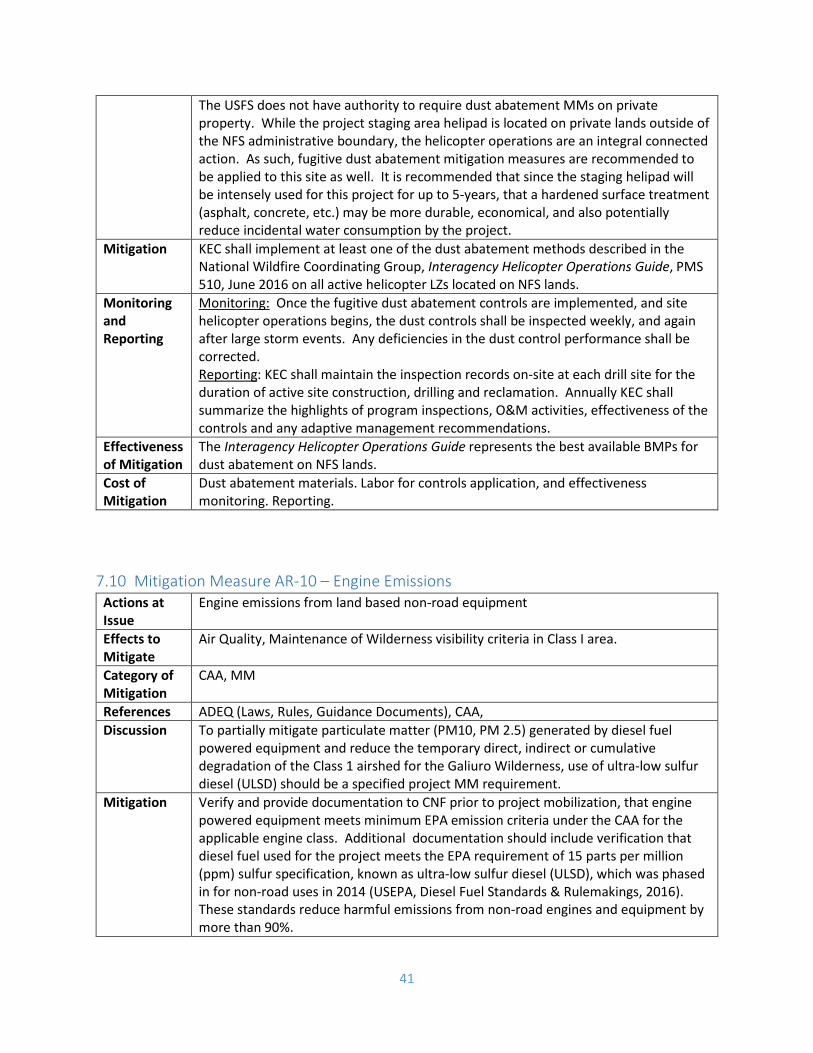
41
The USFS does not have authority to require dust abatement MMs on private property. While the project staging area helipad is located on private lands outside of the NFS administrative boundary, the helicopter operations are an integral connected action. As such, fugitive dust abatement mitigation measures are recommended to be applied to this site as well. It is recommended that since the staging helipad will be intensely used for this project for up to 5-years, that a hardened surface treatment (asphalt, concrete, etc.) may be more durable, economical, and also potentially reduce incidental water consumption by the project.
Mitigation KEC shall implement at least one of the dust abatement methods described in the National Wildfire Coordinating Group, Interagency Helicopter Operations Guide, PMS 510, June 2016 on all active helicopter LZs located on NFS lands.
Monitoring and Reporting
Monitoring: Once the fugitive dust abatement controls are implemented, and site helicopter operations begins, the dust controls shall be inspected weekly, and again after large storm events. Any deficiencies in the dust control performance shall be corrected. Reporting: KEC shall maintain the inspection records on-site at each drill site for the duration of active site construction, drilling and reclamation. Annually KEC shall summarize the highlights of program inspections, O&M activities, effectiveness of the controls and any adaptive management recommendations.
Effectiveness of Mitigation
The Interagency Helicopter Operations Guide represents the best available BMPs for dust abatement on NFS lands.
Cost of Mitigation
Dust abatement materials. Labor for controls application, and effectiveness monitoring. Reporting.
7.10 Mitigation Measure AR-10 – Engine Emissions Actions at Issue
Engine emissions from land based non-road equipment
Effects to Mitigate
Air Quality, Maintenance of Wilderness visibility criteria in Class I area.
Category of Mitigation
CAA, MM
References ADEQ (Laws, Rules, Guidance Documents), CAA, Discussion To partially mitigate particulate matter (PM10, PM 2.5) generated by diesel fuel
powered equipment and reduce the temporary direct, indirect or cumulative degradation of the Class 1 airshed for the Galiuro Wilderness, use of ultra-low sulfur diesel (ULSD) should be a specified project MM requirement.
Mitigation Verify and provide documentation to CNF prior to project mobilization, that engine powered equipment meets minimum EPA emission criteria under the CAA for the applicable engine class. Additional documentation should include verification that diesel fuel used for the project meets the EPA requirement of 15 parts per million (ppm) sulfur specification, known as ultra-low sulfur diesel (ULSD), which was phased in for non-road uses in 2014 (USEPA, Diesel Fuel Standards & Rulemakings, 2016). These standards reduce harmful emissions from non-road engines and equipment by more than 90%.

42
Monitoring and Reporting
Monitoring: Verify that diesel fuel delivered to the project equipment operated on NFS lands is ULSD fuel. Reporting: KEC shall maintain fuel type delivery records either at the project staging site, or on-site at each drill site for the duration of active site construction, drilling and reclamation.
Effectiveness of Mitigation
This Mitigation Measure will help ensure that the project is consistent with CNFs goal of preserving the visibility and other air quality measures (i.e., SO2, NOx, PM10, PM2.5) in the Galiuro Wilderness Federal Class I airshed.
Cost of Mitigation
Cost for use of ultra-low sulfur diesel fuel. Reporting.
7.11 Mitigation Measure SR/WR-11 – Water Supply Pipeline Leakage Detection Actions at Issue
The pipeline that conveys fresh drilling water to the drill pads could develop a leak that could go undetected for a week or more.
Effects to Mitigate
Pipeline leakage could occur at rates and volumes that could cause localized resource damage by eroding soil and transporting sediment to local drainages or streams.
Category of Mitigation
CWA, BMPs (Fac-2. Facility Construction and Stormwater Control), LMRP, MM
References ADEQ (Laws, Rules, Guidance Documents), CWA, USFS (BMPs Fac-2) Discussion There is a potential risk that the water supply pipeline could develop a large leak or
partial failure and subsequently discharge water at rates, volumes, and durations that could cause localized damage to erodible soils and receiving watercourses. The PPEPM on the PoO, is to inspect the pipeline weekly for leaks. However, a substantial amount of erosion and Forest resource damage is possible under some conditions between the proposed inspection frequency. A public comment received suggested that a water metering and monitoring program could be implemented as a pipeline leak detection method. The Forest concurs that an effective leak detection mitigation is reasonable to require. It is believed that the mitigation detailed below would sharply reduce the duration and scale of potential damage to soil and water quality should a detectable pipeline leak develop. This mitigation is also in support of the design elements and goals found in Forest Service BMP ‘FAC-2’ (Appendix C).
Mitigation The intent of this mitigation is for the operator to record and reconcile the transport of water thru the pipeline twice per day. Monitoring, thresholds, corrective actions, and reporting requirements are detailed below. The mitigation will require installation, operation and maintenance of water meters on the water supply pipeline at the point of entry, and points of water usage. The entry point meter may be installed on or about the boundary of the NFS lands (or at the beginning of the pipeline at the project staging area on private lands, see conditions below). One water meter will be required at each intended point of use (presumably at each active drill rig site). The meters shall be maintained in proper operating condition, and repaired or replaced no longer than 5 days after a meter

43
failure. In the event of meter failure the monitoring of the operating meters shall continue. The USFS does not have the authority to require installation of water meter equipment on private property. Therefore, this part of the mitigation is only enforceable at the point which the supply water line enters onto NFS Lands. The ‘entry point’ water meter may be co-located with the backflow preventer (as required in WR-5), and be located on NFS Lands in close proximity to the NFS boundary. Alternatively, the USFS is amenable to water metering installed on private lands at KEC’s option, as long as the metering criteria is met, and is properly monitored and reported.
Monitoring and Reporting
Monitoring: The water metering devices shall be maintained in proper operating condition at all times water is delivered to the water supply piping system upon entering NFS Lands. Water meters shall have a published accuracy of ± 5 %, or better. Readings of all meters shall be taken at approximately same time. The operator shall, at minimum, take twice daily readings, preferably at 12 hour intervals or shift change, at the proponent’s discretion. The operator shall record the meter reading values, totalized water volumes input and discharged thru the pipeline, and the difference in the water balance in percent and gallons. If the recorded water input/discharge volume difference is greater than 15% or 500 gallons in one monitoring interval, or greater than 15% or 1,500 gallons over the past 7-days, will require a complete on-the-ground visual inspection during the next available daylight hours. Reporting: KEC shall report all pipeline leaks that result in more than 1 cubic yard of soil displacement or any visible evidence of sediment actively entering or has entered any NHD mapped stream. These events shall be reported to the Forest Minerals Administrator within 72-hours of discovery. Annually, KEC shall summarize the following: monitoring results (i.e., total water input, total water discharged at points of usage, and total water losses), pipe leakage events and repairs made, and overall effectiveness of the leak detection program.
Effectiveness of Mitigation
This mitigation will sharply reduce the potential for medium to large pipeline water leaks (that could cause considerable soil erosion and water quality impacts), to go undetected for days or weeks.
Cost of Mitigation
Nominal. Costs over and above the PPEPM in the PoO are: procuring and installing the water meters (est. $600 - $1200), daily monitoring, and annual reporting.
8 Affected Environment
8.1 Climate Temperature and Precipitation - The climate of the project area is typical of a moderately high elevation Arizona desert, with warm summers and moderate winter temperatures. The area receives approximately 20 inches of precipitation annually (WRCC, 2016). The area also experiences a bimodal precipitation pattern with short duration, high intensity monsoon thunderstorms in the summer months

44
(July to Mid-September), and more prolonged storms that are associated with the passage of low pressure systems off the Pacific Ocean in the winter months (December – March). Fall and especially spring seasons are frequently very droughty. However, precipitation is infrequently but substantially increased from hurricane remnants in the months of September – November.
The El Niño-Southern Oscillation (ENSO), which is also known as El Niño and La Niña, are the warm and cool fluctuations of recurring climate patterns across the Pacific Ocean. The pattern alternates irregularly every two to seven years. Each period triggers predictable disruptions of temperature, precipitation, and winds (NOAA website accessed 8/29/16 https://www.climate.gov/enso ). In Arizona, El Niño will often result in increased winter precipitation, and decreased monsoon precipitation. La Niña can result in opposite effects to normal seasonal precipitation.
Table 2 below, shows PRISIM 30-year climate statistics for temperature and precipitation in the project area.
Table 2 - 1981-2010 Monthly Climate Summary, Location: Lat: 32.7296 Lon: -110.4437 Elev: 4629ft
Jan
Feb
Mar
Apr
May
Jun
Jul
Aug
Sep
Oct
Nov
Dec
Annu
al
Avg. Max. Temp. (F) 55.1 58.3 64.1 72.8 82.9 91.7 92.3 89.9 86.6 77.0 64.7 55.2 74.2 Avg. Min. Temp. (F) 32.4 33.8 37.4 42.0 51.0 60.1 64.9 63.1 58.4 48.5 38.8 31.8 46.8 Avg. Precipitation (in) 2.25 2.05 1.97 0.69 0.35 0.21 2.91 2.95 1.71 1.38 1.41 2.17 20.04
Source: Western Regional Climate Center and PRISIM, accessed 8/11/16
Winds - The closest meteorological station with available wind data compiled for annual average wind rose plots is the Safford municipal airport Automatic Surface Observation System (ASOS) station. Given the similarities of the basin and range topography orientation in both the project area and the Safford station location, it is judged that the Safford data should be reasonably comparable to wind conditions at the project area.
Meteorological parameters such as stability class, mixing height and inversion layers were not researched or acquired for this analysis. As the total project emissions are anticipated to be below ADEQ/EPA permitting thresholds, dispersion modeling is judged to not be necessary for this project.
The data indicates that prevailing winds average 8.0 miles per hour. The data also exhibit a bimodal pattern with the most frequent and strongest winds from the WNW, with a secondary and lighter ESE prevailing wind. http://mesonet.agron.iastate.edu/sites/windrose.phtml?station=SAD&network=AZ_ASOS

45
Figure 1- Annual Average Wind Rose Plot for Safford Municipal Airport
8.2 Physiographic Setting The project is situated in the Basin and Range physiographic province, which is characterized by northerly trending parallel alternating broad intermountain valleys and high mountain ranges. The ranges are generally block faulted on the west and tilted easterly (Hunt, C.B., 1974). Down-faulted valleys are filled in with alluvial fans, pediments and floodplains. The provinces located northerly of the Basin and Range are the Transition Zone in central Arizona, followed by the Colorado Plateau in Northern Arizona.
8.3 General Area Topography Topography - The project is located in the northwesterly corner of the Galiuro Mountain range (Figure 2), in the Safford RD, and approximately 12 miles easterly of the Town of Mammoth, AZ. From the peaks of Cake Mtn. (elevation 6522 MSL) and Biscuit Peak (approx. 6600 MSL), the land steeply declines off the western flank in deep ravines to the boundary of the NFS lands (approx. 4600-5600 MSL, variable). Beyond the NFS lands the topography descends more gradually on the western mountain-front piedmont to the San Pedro River (approx. 3600 MSL). The San Pedro flows in a wide alluvial channel northwesterly towards the Gila River (approx. 1800 MSL).

46
Watersheds - The general project area is within the Copper Creek (6th HUC 150502030805) and Clark Wash (6th HUC 150502030801) sub-watersheds (Figure 2). Both are tributary to the San Pedro River. Pipeline Canyon and Marics Canyon are tributary to Copper Creek.

47
Figure 2- Area Topography, Watersheds and Proposed Drill Sites

48
8.4 Geologic Setting The project is located in the northwesterly portion of the Galiuro Mountains. The Galiuros are rugged block faulted mountains within the Basin and Range physiographic province. The surficial geology of the project area and all drill sites is described as Tertiary andesitic rocks (symbol Ta in Figure 3) and are composed of andesite, lava flows, breccia deposits, and interbedded sedimentary rocks (Drewes, H., 1996). There are no mapped major or minor faults, or other notable structures mapped in the project area. The prominent fault in the range is the NNW trending Central Galiuro Fault (a.k.a. Rattlesnake Fault), which is not shown to extend into the project area. Also part of the site surficial geology (but are not depicted on the USGS maps), are stringers of shallow Quaternary alluvium present along the stream channels. These are somewhat discontinuous, but can be of sufficient width and depth to support important riparian habitat and vegetation.
The project area is noted in the literature to have a high potential for hosting a porphyry copper-molybdenum (Cu-Mo) deposit at depth (Bultman, M. W., Drews, H., 1996). Rock units below the Tertiary andesite, at a depth of less than 1 km, are believed to be Paleozoic sedimentary rocks of the Martin Formation and Escabrosa Limestone, and these are the units with the potential to host Cu-Mo ore deposits.

49
Figure 3 - Geology - USGS (Drewes, H., 1996)
8.5 Hydrologic Setting
8.5.1 Conceptual Hydrologic Model In the context of the regional hydrology of the San Pedro river valley, the project site is located in the fractured hardrock uplands, where orographic lift generates higher precipitation amounts, and runoff rates and ratios are high. Runoff generation is high due to the presence of fairly shallow soils, relatively lower permeability bedrock, and steep topography. The uppermost lithologic unit in the project area is an approximately 1 km thick, Tertiary andesitic unit. Groundwater in the andesite unit would most likely behave as an unconfined fractured bedrock aquifer. Underlying the andesite unit are well consolidated Paleozoic sedimentary rocks. These units would be expected to be groundwater saturated and fractured to some degree, there is some potential for karst, pseudo-karst or confined aquifer conditions to exist. The highlands would be a groundwater recharge area, but its effectiveness is limited by the relatively low permeability of the surficial rocks, and the limited time runoff is available for deep infiltration as storm-flows pass through the steep gradient upland portion of the basins. Groundwater depths can be highly variable, but the perennial springs indicate the depth to groundwater is quite shallow, at least in the mountain ravines. Well yields in this area would be anticipated to range from
Project Area

50
very low to rarely, moderately high where multiple sets of transmissive fractures intersect. Surface water channels in the project area are believed to be generally intermittent in nature.
Just outside of the NFS lands the terrain becomes largely piedmont, with generally more permeable rocks with higher primary and secondary porosity and appreciable deposits of unconsolidated basin-fill alluvial sediment. This is sometimes referred to as the mountain-front recharge zone. Groundwater depths can be substantial in this zone (100’s of feet), but the aquifers encountered at depth can be very productive. Surface waters in this area are expected to transition from intermittent to predominantly ephemeral thru basin-fill units. Still, interrupted/intermittent reaches are possible where they traverse across consolidated, intrusive or metamorphic units.
The groundwater discharge zone for the project basin would be at or near the San Pedro River, approximately 10 miles westerly of the project area. Groundwater depths are expected to be shallow in this zone. Aquifers are typically composed of unconsolidated alluvium and are generally very productive. Zones of clays and slits in the subsurface can result in perched or semi-confined aquifer conditions. Surface waters in the discharge zone may be expected to be perennial to intermittent.
General Watershed Information, Water Availability and Uses in the lower San Pedro Watershed (ADWR, 2016, on-line Water Atlas accessed 9/1/16).
Water Resources – Lower San Pedro:
• Lower San Pedro Basin Area: 1,624 mi2 • Major Aquifer(s): Basin Fill and Recent Stream Alluvium • Mean annual flow of the San Pedro River at Winkelman: 37,803 acre-feet/year (ac-ft/yr) • Natural recharge estimates range from 24,000 acre-feet per year to 29,000 ac-ft/yr. • Estimated Water Currently in Aquifer Storage, in acre-feet (ac-ft): 12,000,000 - 25,600,000 ac-ft
Cultural Water Demands – Lower San Pedro:
• Total groundwater demand has decreased from 1971 to 2005, with an average of 25,700 ac-ft of Groundwater pumped per year in the period from 2001-2005.
• Surface water diversions have also decreased from 1971 to 2005 with approximately 1,300 ac-ft diverted per year in the period from 1991 – 2005 for agricultural and municipal uses.
• The largest single demand for groundwater is industrial with an average of 15,900 ac-ft per year pumped in the period from 2001-2005.
• There are numerous mines in the basin; the active Ray Mine north of Kearny, a small Inactive mine in the vicinity of Hayden and numerous inactive mines including the Mammoth Mine and San Manuel Mine in the vicinity of Mammoth.
• Groundwater Pumping Average (2001-2005) • 2300 ac-ft/yr - Municipal • 15900 ac-ft/yr - Industrial (Note, industrial pumping was 26,300 ac-ft/yr from 1996-2001
before the San Manuel mine shutdown began 1999) • 7500 ac-ft/yr – Agriculture
TOTAL 25,700 ac-ft/yr • Surface Water Diversions
• 300 ac-ft/yr - Municipal

51
• <1000 ac-ft/yr - Agricultural TOTAL 1,300 ac-ft/yr
• Cultural Effluent Generation - 708 ac-ft/yr (Source: ADWR, 2016, Water Atlas for lower San Pedro watershed, accessed 8/1/16)
8.5.2 Groundwater 8.5.2.1 Aquifers and Groundwater Flow System Geology, to a large degree, determines hydrogeology. Understanding of the site geology will influence the accuracy of the interpretation of the site hydrogeology and determination of risks associated with the proposed activity.
There are four broad types of aquifers: unconfined, confined, karst, and multi-layered. Aquifers can consist of unconsolidated sediments, consolidated sediments, or crystalline bedrock (igneous or metamorphic). Both unconsolidated and consolidated sediments can potentially behave as either porous media or fractured material, depending on specific conditions in the area under consideration. Aquifers composed of crystalline rock generally behave as fractured material. (Gurrieri, J., Holm, M.R., 2014)
“Unconfined aquifers are also referred to as water table or phreatic aquifers. Their primary characteristic is that the groundwater body typically has free exchange of pressure and moisture with the unsaturated zone and, indirectly, the atmosphere. Where they intersect the land surface, they may form springs, and frequently provide a significant fraction of the water in streams.
Confined or artesian aquifers contain groundwater under pressure. When penetrated, the water level in the drill hole will rise above the top of the aquifer and may reach the ground surface. The level the water rises to is called the potentiometric surface of the aquifer. This level can even be above the groundwater level of overlying aquifers. Confined, or artesian, aquifers usually occur in deeper layered or stratified sediments in large sedimentary basins and in fractured rock aquifers with defined preferential flow paths (e.g., faults) in areas of high relief. The most significant characteristic of these aquifers is that major changes in the water level may be encountered as a result of aquifer penetration by a drill hole to the extent that significant water flow may occur at the surface. These aquifers, because of large pressure differentials, are highly susceptible to cross-aquifer contamination such as saline water invading a lower pressure, freshwater aquifer.
Semi-confined aquifer conditions are sometimes encountered within fractured rock aquifers. These aquifers are susceptible to cross-structure contamination where the geochemistry of one intercepted geologic structure is very different than the geochemistry of another intercepted geologic structure. Drilling in these aquifer systems requires detailed planning and special drilling techniques and abandonment procedures. The structure (jointing, fracturing, and faulting) may create areas that confine or restrict the flow of groundwater. When faults, other significant structures acting as aquitards (layers of low permeability), or isolated water-filled fracture networks at depth are penetrated by drilling, increased artesian pressures may occur in the hole. Generally, these pressures subside rapidly due to the low storativity (ability of the host rock to

52
store water) of these aquifers or fracture networks. However, if these types of aquifers are encountered in an exploration drill hole, they can flow under considerable pressure for several days, weeks, or even years, producing large volumes of water. The water may contain elevated concentration of dissolved minerals, such as salts. Conversely, drilling through a major confining structure may cause a sudden loss of circulation as drill fluids flow into a lower pressure or unsaturated zone.
Many exploration projects are conducted in fractured crystalline rock types. In those settings, near-surface groundwater is generally unconfined to semi-confined depending on the local nature of the rock. These rocks are widely characterized as low producers of groundwater. However, where they are sufficiently fractured, they may produce enough groundwater locally for various water supply needs” (Gurrieri, J., Holm, M.R., 2014)
Information on the surficial bedrock geology of the site was presented in Section 8.4 (Bultman, M. W., Drews, H., 1996; and Drews, H., 1996). However, there is very limited information on the bedrock at depth, aquifer(s) present, and the groundwater flow system in the project area. There are no known well logs within or near the project area that would normally provide very useful information. Existing wells and well data are scattered about in areas downgradient and outside of NFS lands. Unfortunately, the geologic mapping indicates that most of these off-site wells are in different rock and aquifer types, and flow regimes, so the information is not particularly germane to the subject site. Some hydrologic factors are known or can be reasonably assumed to characterize the site:
• Several springs are known to exist in the project area, and potentially help to establish the water table as relatively shallow, at least in the vicinity of these features.
• The topographic relief in the area is substantial and the water table gradient will generally, but more subtly, reflect the topography. This information helps define the groundwater basin and general flow directions.
• Surface water divides (topographic watersheds) and groundwater divides (basins) are likely coincidently located.
• Geologic mapping at the surface indicates andesitic crystalline bedrock with interlayered sedimentary units. There is no information indicating structural features that could vastly alter groundwater flow patterns.
• While geologic mapping does not depict any major faults in the area, observation of fracture traces and lineaments on aerial photography indicate the presence of a moderate number of near vertical joints or faults with some preferential directions in fracture orientation. Prominent directions inferred are approximately N 25⁰ W, N 34⁰ W, and N 65⁰ E. These features exist in the vicinity of Norton Spring, and are expected to be present throughout the project area (Figure 4).
• Groundwater movement in fractured bedrock is largely thru the secondary porosity and highly permeable fracture zones.
• Some alluvial sediment occurs along stream courses in the project area, and supports shallow unconfined groundwater aquifers, and ecologically important riparian vegetation and habitat.
Given this information, it is anticipated that an unconfined fractured bedrock aquifer would be present and encountered while drilling within the project area. It is also very possible that some degree of semi-confined aquifer conditions would be encountered as the boreholes advance in depth. However, there

53
is a high degree of uncertainty associated with these expectations of groundwater condition and behavior.
An unconfined alluvial aquifer is anticipated to be present along the major stream courses. The areal extent of this aquifer is highly constrained and limited to the unconsolidated streambed and floodplain deposits, largely contained within bedrock canyons. These limited aquifers may be perched systems and may function somewhat independently of the bedrock aquifer. Regardless of degree of connection to the areal bedrock aquifer, these channel-based aquifers support riparian habitat in the project area.
Figure 4 - Cursory Fracture Trace and Lineament Analysis of the Norton Springs / Drill Site Gal01P area

54
8.5.2.2 Groundwater Quality There is little known information on groundwater quality in the project area, particularly concerning the bedrock aquifers. Available water quality data of single grab samples from Norton Spring by the USFS, and the Old Mercer Ranch dug well by KEC, are reasonably indicative of shallow aquifer water quality in the immediate vicinity of Scanlon Wash. At these shallow aquifer depths, the data do not indicate any substantial acidic or priority pollutant metals water quality problems in this area.
To make some approximation of potential groundwater quality at depth in the bedrock aquifer(s), the following factors are reasonably known:
• The drilling project is intended to determine if an economic copper ore deposit is present below the surface of the project area. Known economic copper ore deposits in the area (i.e., Oracle Ridge, San Manuel) have been predominantly sulfide deposits.
• USGS Geological information indicates the potential for a sulfide Cu-Au-Mo deposit in the Paleozoic units approximately 1 km below the surface of the project area.
Important factors that are unknown:
• Actual geologic units present through the potential 5000’ (or more) boring depths. • Actual aquifer presence, absence, productivity, hydraulic gradients and water quality
throughout the project area down to the potential drilling depths.
Given the apparent target of the mineral exploration project, and the USGS informed assessment, predicting a sulfide Cu-Au-Mo deposit at depth, it is reasonably probable that groundwater encountered in the boreholes at some point would likely be “mineralized waters” as defined by ADWR.
8.5.3 Surface Water 8.5.3.1 Project Watersheds The project area is located within two 6th code Hydrologic Unit Code (HUC) sub-watersheds of the greater San Pedro river valley (see Figure 5). Table 3 lists the proposed drill sites that are located in each sub-watershed.
Table 3 - Project Area Streams, Watersheds and Drill Sites
Stream Name HUC 6th Code Watersheds
Proposed Drill Sites
Copper Creek 150502030805 (Copper Creek)
Gal10P, Gal12P, Gal13P
Pipeline Canyon 150502030805 (Copper Creek)
Gal09P, Gal14P
Marics Canyon 15150502030805 (Copper Creek)
Gal 03P, Gal06P, Gal07P
Scanlon Wash 150502030801 (Clark Wash)
Gal01P, Gal02P, Gal04P, Gal05P