Embed Size (px)
Citation preview
©Copyright Task Force Tips LLC 2014-2021 1 LIA-208 May 19, 2021 Rev05
TASK FORCE TIPS LLCMADE IN USA · tft.com
3701 Innovation Way, Valparaiso, IN 46383-9327 USA800-348-2686 · 219-462-6161 · Fax 219-464-7155
G-Force
INSTRUCTION FOR INSTALLATION, OPERATION, AND MAINTENANCE
JUMBO LOW PROFILEBALL INTAKE VALVE (BIV)
DANGER Understand manual before use. Operation of this device without understanding the manual andreceiving proper training is a misuse of this equipment. Obtain safety information at tft.com/serial-number. This equipment is intended for use by trained and qualified emergency services personnel forfirefighting. All personnel using this equipment shall have completed a course of educationapproved by the Authority Having Jurisdiction (AHJ).This instruction manual is intended to familiarize firefighters and maintenance personnel with theoperation, servicing, and safety procedures associated with this product. This manual should bekept available to all operating and maintenance personnel.
LEFT DRIVE RIGHT DRIVE
AXD1ST-NX-TJumbo Low ProfileBall Intake Valve
Top Crankwith Pressure Relief Valve
AZD1ST-NX-Twithout Pressure Relief Valve
(not shown)
AXD1ST-NX-FJumbo Low ProfileBall Intake Valve
Front Crankwith Pressure Relief Valve
AZD1ST-NX-Fwithout Pressure Relief Valve
(not shown)
AXD1ST-NX-RCJumbo Low ProfileBall Intake Valve
Electrically Actuatedwith Pressure Relief Valve
AZD1ST-NX-RCwithout Pressure Relief Valve
(not shown)
AXE1ST-NX-RCJumbo Low ProfileBall Intake Valve
Electrically Actuatedwith Pressure Relief Valve
AZE1ST-NX-Fwithout Pressure Relief Valve
(not shown)
AXE1ST-NX-FJumbo Low ProfileBall Intake Valve
Front Crankwith Pressure Relief Valve
AZE1ST-NX-Fwithout Pressure Relief Valve
(not shown)
AXE1ST-NX-TJumbo Low ProfileBall Intake Valve
Top Crankwith Pressure Relief Valve
AZE1ST-NX-Twithout Pressure Relief Valve
(not shown)
©Copyright Task Force Tips LLC 2014-2021 2 LIA-208 May 19, 2021 Rev05
The member companies of FEMSA that provide emergency response equipment and services want responders to know and understand the following:
1. Firefighting and Emergency Response are inherently dangerous activities requiring proper training in their hazards and the use of extreme caution at all times.
2. IT IS YOUR RESPONSIBILITY to read and understand any user’s instructions, including purpose and limitations, provided with any piece of equipment you may be called on to use.
3. IT IS YOUR RESPONSIBILITY to know that you have been properly trained in Firefighting and/or Emergency Response and in the use, precautions, and care of any equipment you may be called upon to use.
4. IT IS YOUR RESPONSIBILITY to be in proper physical condition and to maintain the personal skill level required to operate any equipment you may be called upon to use.
5. IT IS YOUR RESPONSIBILITY to know that your equipment is in operable condition and has been maintained in accordance with the manufacturer’s instructions.
6. Failure to follow these guidelines may result in death, burns or other severe injury.
Fire and Emergency Manufacturers and Service Association, Inc. PO Box 147, Lynnfield, MA 01940 • www.FEMSA.org
© 2020 FEMSA. All Rights Reserved.
PERSONAL RESPONSIBILITY CODE
DANGER
SUPPORTING MATERIALS
The following document contains supporting safety and operating information pertaining to the equipment described in this manual.
LIA-202 Pressure Relief Valve Manual
©Copyright Task Force Tips LLC 2004-2019 LIA-202 November 12, 2019 Rev05
MANUAL: Pressure Relief Valve
INSTRUCTIONS FOR SAFE OPERATION AND MAINTENANCE
WARNINGUnderstand manual before use. Operation of this device without understanding the manual and receiving proper training is a misuse of this equipment. Obtain safety information at tft.com/ serialnumber.
This instruction manual is intended to familiarize � re� ghters and maintenance personnel with the operation, servicing, and safety procedures associated with this product.This manual should be kept available to all operating and maintenance personnel.
Flange Mounted PRV
Flange Mounted PRVwith Galvanic Isolator
Flange mounted PRVs are available with a variety of outlets. Consult the catalog, factory, or tft.com to � nd the con� guration for your application.
TASK FORCE TIPS LLCMADE IN USA • TFT.com
3701 Innovation Way, Valparaiso, IN 46383-9327 USA800-348-2686 • 219-462-6161 • Fax 219-464-7155

©Copyright Task Force Tips LLC 2014-2021 3 LIA-208 May 19, 2021 Rev05
TABLE OF CONTENTS
1.0 MEANING OF SAFETY SIGNAL WORDS2.0 SAFETY3.0 GENERAL INFORMATION
3.1 SPECIFICATIONS3.1.1 MECHANICAL3.1.2 ELECTRICAL
3.2 VARIOUS MODELS AND TERMS3.3 CORROSION3.4 USE WITH SALT WATER
4.0 OVERALL DIMENSIONS5.0 INSTALLATION
5.1 MOUNTING THE APPLIANCE5.2 MOUNTING THE DISPLAY ENCLOSURE5.3 ELECTRIC INSTALLATION AND WIRING
5.3.1 TESTING THE ELECTRICAL INSTALLATION5.4 BIV RC MANUAL OVERRIDE5.5 CHANGING THE OFFSET OF THE CRANK HANDLE5.6 CHANGING COUPLING LOCK-OUT5.7 PEG OPTION5.8 STORZ SUCTION GASKET REQUEST
6.0 USE6.1 ELBOW6.2 MANUAL VALVE OPERATION6.3 RC VALVE OPERATION6.4 AIR VENT AND WATER DRAIN6.5 PRESSURE RELIEF VALVE (PRV)
6.5.1 RELIEF VALVE PRESSURE SETTING6.6 PRESSURE LOSS6.7 SUCTION SCREEN
7.0 TEN YEAR EXTENDED WARRANTY FOR JBIV-LP SERIES VALVES8.0 MAINTENANCE
8.1 TROUBLESHOOTING8.2 SERVICE TESTING8.3 REPAIR8.4 CRANKSHAFT OVERRIDE AND REPLACEMENT
8.4.1 EMERGENCY CRANKSHAFT OVERRIDE8.4.2 DIAGNOSING CRANKSHAFT FAILURE8.4.3 CRANKSHAFT REPLACEMENT
9.0 EXPLODED VIEW AND PARTS LISTS10.0 OPERATION AND INSPECTION CHECKLIST11.0 TEMPLATES
11.1 DISPLAY ENCLOSURE11.2 QUICK CONNECT PLUG
©Copyright Task Force Tips LLC 2014-2021 4 LIA-208 May 19, 2021 Rev05
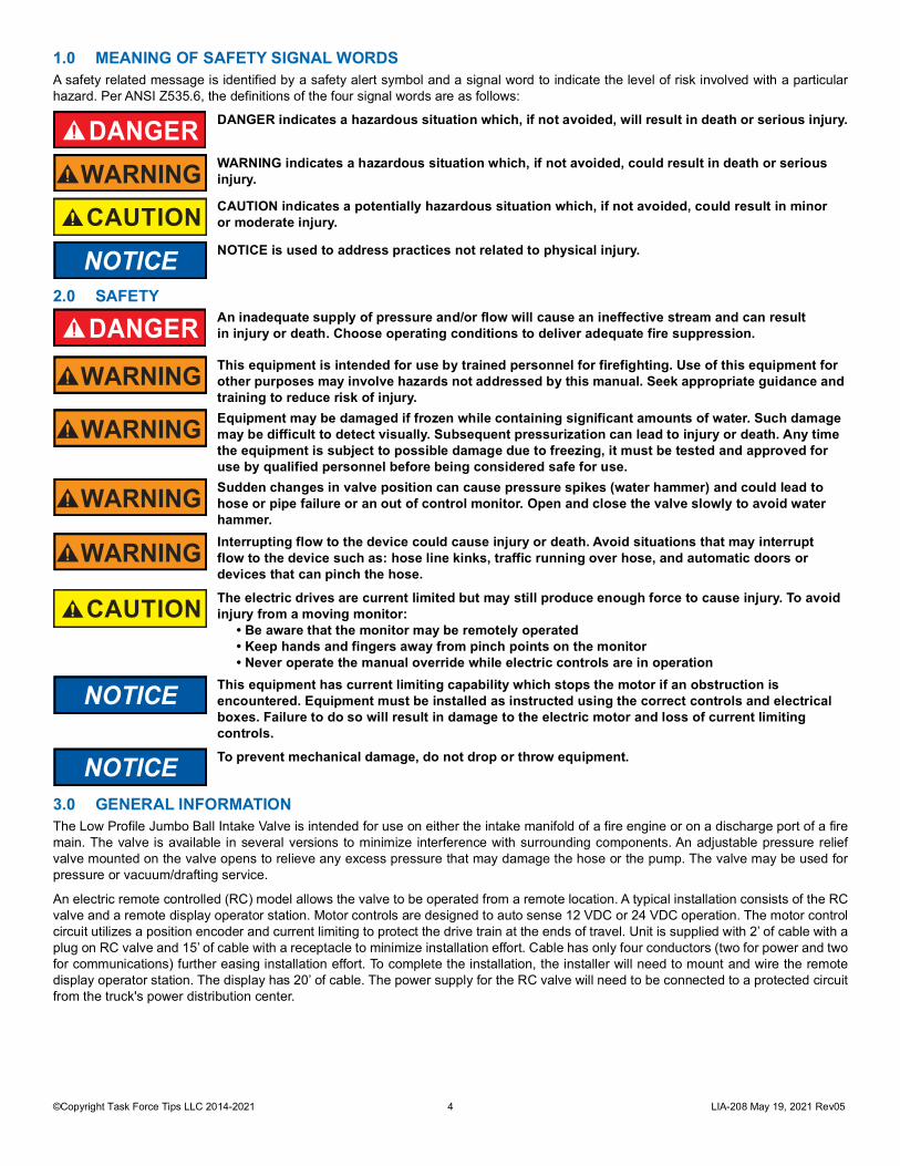
1.0 MEANING OF SAFETY SIGNAL WORDSA safety related message is identified by a safety alert symbol and a signal word to indicate the level of risk involved with a particularhazard. Per ANSI Z535.6, the definitions of the four signal words are as follows:
2.0 SAFETY
3.0 GENERAL INFORMATIONThe Low Profile Jumbo Ball Intake Valve is intended for use on either the intake manifold of a fire engine or on a discharge port of a firemain. The valve is available in several versions to minimize interference with surrounding components. An adjustable pressure reliefvalve mounted on the valve opens to relieve any excess pressure that may damage the hose or the pump. The valve may be used forpressure or vacuum/drafting service.
An electric remote controlled (RC) model allows the valve to be operated from a remote location. A typical installation consists of the RCvalve and a remote display operator station. Motor controls are designed to auto sense 12 VDC or 24 VDC operation. The motor controlcircuit utilizes a position encoder and current limiting to protect the drive train at the ends of travel. Unit is supplied with 2’ of cable with aplug on RC valve and 15’ of cable with a receptacle to minimize installation effort. Cable has only four conductors (two for power and twofor communications) further easing installation effort. To complete the installation, the installer will need to mount and wire the remotedisplay operator station. The display has 20’ of cable. The power supply for the RC valve will need to be connected to a protected circuitfrom the truck's power distribution center.
DANGER DANGER indicates a hazardous situation which, if not avoided, will result in death or serious injury.
WARNING WARNING indicates a hazardous situation which, if not avoided, could result in death or serious injury.
CAUTION CAUTION indicates a potentially hazardous situation which, if not avoided, could result in minoror moderate injury.
NOTICE NOTICE is used to address practices not related to physical injury.
DANGER An inadequate supply of pressure and/or flow will cause an ineffective stream and can resultin injury or death. Choose operating conditions to deliver adequate fire suppression.
WARNING This equipment is intended for use by trained personnel for firefighting. Use of this equipment forother purposes may involve hazards not addressed by this manual. Seek appropriate guidance and training to reduce risk of injury.
WARNING Equipment may be damaged if frozen while containing significant amounts of water. Such damage may be difficult to detect visually. Subsequent pressurization can lead to injury or death. Any time the equipment is subject to possible damage due to freezing, it must be tested and approved for use by qualified personnel before being considered safe for use.
WARNING Sudden changes in valve position can cause pressure spikes (water hammer) and could lead to hose or pipe failure or an out of control monitor. Open and close the valve slowly to avoid water hammer.
WARNING Interrupting flow to the device could cause injury or death. Avoid situations that may interruptflow to the device such as: hose line kinks, traffic running over hose, and automatic doors ordevices that can pinch the hose.
CAUTION The electric drives are current limited but may still produce enough force to cause injury. To avoidinjury from a moving monitor:
• Be aware that the monitor may be remotely operated• Keep hands and fingers away from pinch points on the monitor• Never operate the manual override while electric controls are in operation
NOTICE This equipment has current limiting capability which stops the motor if an obstruction is encountered. Equipment must be installed as instructed using the correct controls and electrical boxes. Failure to do so will result in damage to the electric motor and loss of current limiting controls.
NOTICE To prevent mechanical damage, do not drop or throw equipment.
©Copyright Task Force Tips LLC 2014-2021 5 LIA-208 May 19, 2021 Rev05
3.1 SPECIFICATIONS3.1.1 MECHANICAL
Table 3.1.1
3.1.2 ELECTRICAL
Table 3.1.2
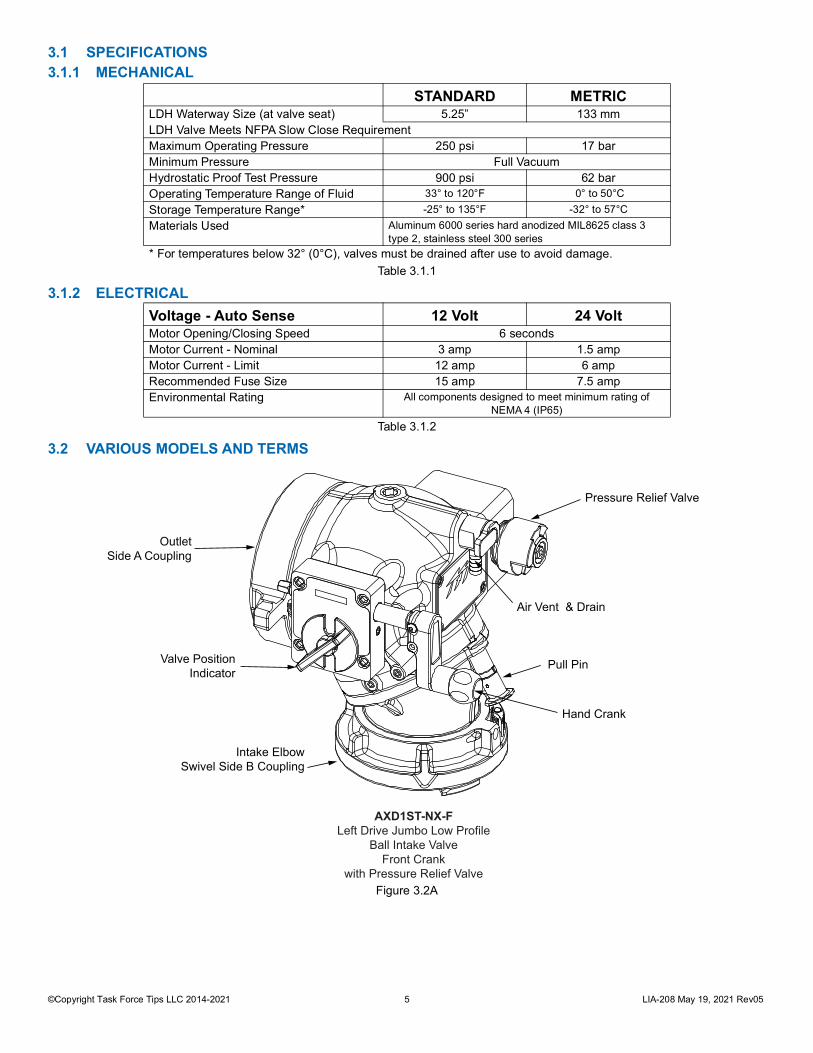
3.2 VARIOUS MODELS AND TERMS
Figure 3.2A
STANDARD METRICLDH Waterway Size (at valve seat) 5.25” 133 mmLDH Valve Meets NFPA Slow Close RequirementMaximum Operating Pressure 250 psi 17 barMinimum Pressure Full VacuumHydrostatic Proof Test Pressure 900 psi 62 barOperating Temperature Range of Fluid 33° to 120°F 0° to 50°CStorage Temperature Range* -25° to 135°F -32° to 57°CMaterials Used Aluminum 6000 series hard anodized MIL8625 class 3
type 2, stainless steel 300 series* For temperatures below 32° (0°C), valves must be drained after use to avoid damage.
Voltage - Auto Sense 12 Volt 24 VoltMotor Opening/Closing Speed 6 secondsMotor Current - Nominal 3 amp 1.5 ampMotor Current - Limit 12 amp 6 ampRecommended Fuse Size 15 amp 7.5 ampEnvironmental Rating All components designed to meet minimum rating of
NEMA 4 (IP65)
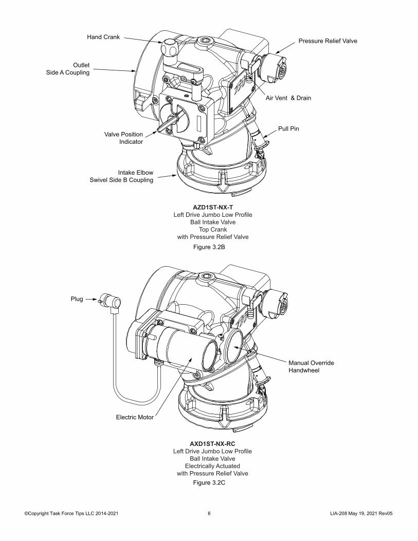
Hand Crank
Pressure Relief Valve
Air Vent & Drain
Pull Pin
Intake ElbowSwivel Side B Coupling
Valve PositionIndicator
OutletSide A Coupling
AXD1ST-NX-FLeft Drive Jumbo Low Profile
Ball Intake ValveFront Crank
with Pressure Relief Valve
©Copyright Task Force Tips LLC 2014-2021 6 LIA-208 May 19, 2021 Rev05
Figure 3.2B
Figure 3.2C
Pressure Relief Valve
Air Vent & Drain
Pull Pin
Intake ElbowSwivel Side B Coupling
Valve PositionIndicator
Hand Crank
OutletSide A Coupling
AZD1ST-NX-TLeft Drive Jumbo Low Profile
Ball Intake ValveTop Crank
with Pressure Relief Valve
Manual OverrideHandwheel
Plug
Electric Motor
AXD1ST-NX-RCLeft Drive Jumbo Low Profile
Ball Intake ValveElectrically Actuated
with Pressure Relief Valve
©Copyright Task Force Tips LLC 2014-2021 7 LIA-208 May 19, 2021 Rev05
3.3 CORROSIONAluminum parts are hard anodized. All castings are then powder coated inside and out to help prevent corrosion. Most hose couplingsare attached using polymer bearing rings which provide electrical insulation to help prevent galvanic corrosion. The effects of corrosioncan be minimized by good maintenance practice.
3.4 USE WITH SALT WATERUse with salt water is permissible provided the equipment is thoroughly cleaned with fresh water after each use. The service life of theequipment may be shortened due to the effects of corrosion, and is not covered under warranty.
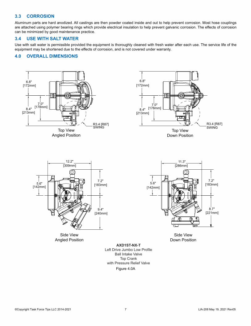
4.0 OVERALL DIMENSIONS
Figure 4.0A
7.2"
8.7"
5.6" [142mm]
11.3" [286mm]
6.8" [172mm]
8.4" [213mm]
7.0" [178mm]
R3.4 [R87]SWING
Side ViewAngled Position
Side ViewDown Position
12.2" [309mm]
7.2" [183mm]
9.4" [240mm]
5.6" [142mm]
R3.4 [R87]SWING
6.8" [172mm]
8.4" [213mm]
7.0" [178mm]
[183mm]
[221mm]
AXD1ST-NX-TLeft Drive Jumbo Low Profile
Ball Intake ValveTop Crank
with Pressure Relief Valve
Top ViewAngled Position
Top ViewDown Position
©Copyright Task Force Tips LLC 2014-2021 8 LIA-208 May 19, 2021 Rev05
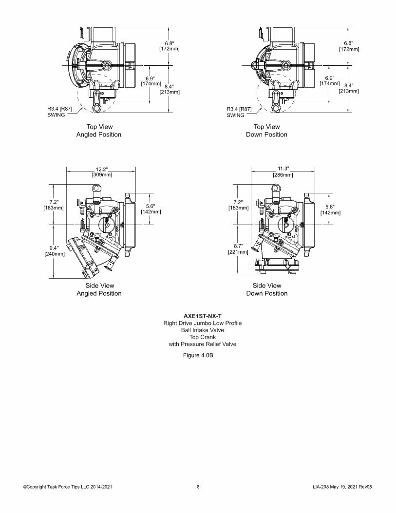
Figure 4.0B
Side ViewAngled Position
Side ViewDown Position
6.9" [174mm]
6.8" [172mm]
8.4" [213mm]
6.9" [174mm]
6.8" [172mm]
8.4" [213mm]
R3.4 [R87]SWING
R3.4 [R87]SWING
11.3" [286mm]
8.7" [221mm]
7.2" [183mm] 5.6"
[142mm]5.6"
[142mm]
12.2" [309mm]
7.2" [183mm]
9.4" [240mm]
Top ViewAngled Position
Top ViewDown Position
AXE1ST-NX-TRight Drive Jumbo Low Profile
Ball Intake ValveTop Crank
with Pressure Relief Valve
©Copyright Task Force Tips LLC 2014-2021 9 LIA-208 May 19, 2021 Rev05
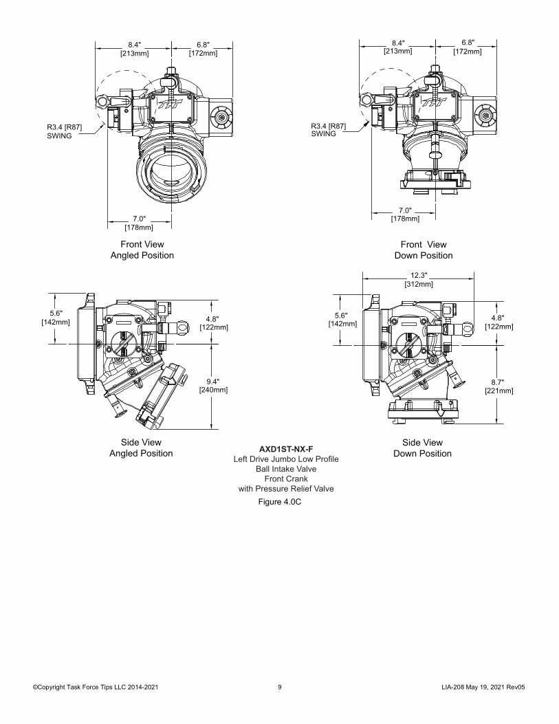
Figure 4.0C
Side ViewDown Position
Side ViewAngled Position
12.3" [312mm]
5.6" [142mm]
4.8" [122mm]
8.7" [221mm]
8.4" [213mm]
6.8" [172mm]
R3.4 [R87]SWING
7.0" [178mm]
5.6" [142mm] 4.8"
[122mm]
9.4" [240mm]
8.4" [213mm]
6.8" [172mm]
7.0" [178mm]
R3.4 [R87]SWING
Front ViewDown Position
Front ViewAngled Position
AXD1ST-NX-FLeft Drive Jumbo Low Profile
Ball Intake ValveFront Crank
with Pressure Relief Valve
©Copyright Task Force Tips LLC 2014-2021 10 LIA-208 May 19, 2021 Rev05
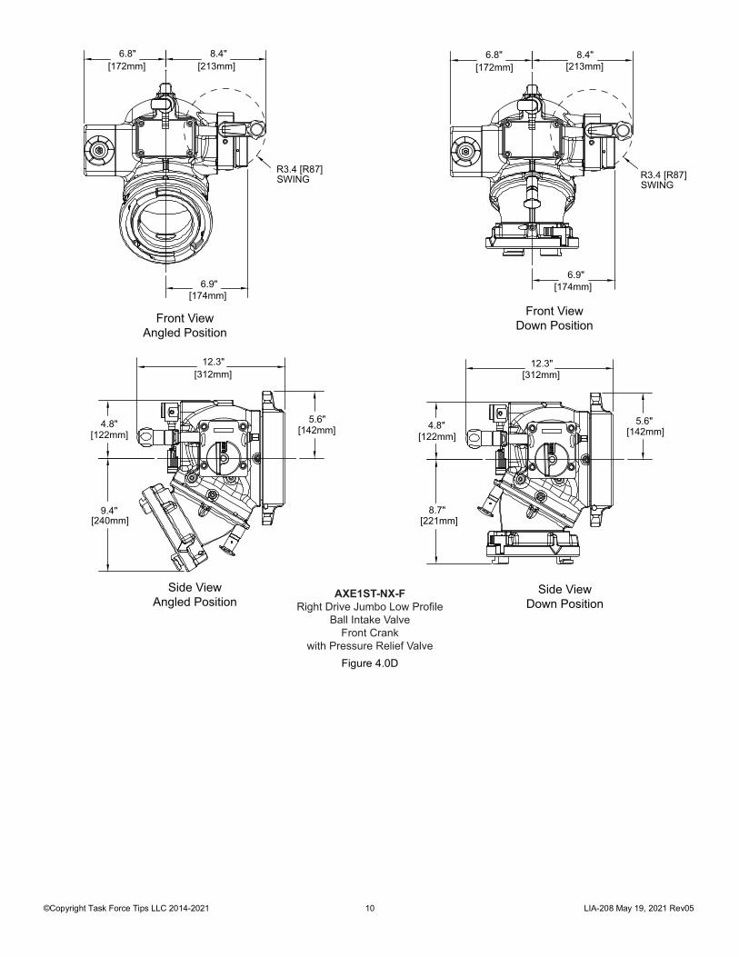
Figure 4.0D
8.4" [213mm]
6.8" [172mm]
12.3" [312mm]
5.6" [142mm]4.8"
[122mm]
8.7" [221mm]
R3.4 [R87]SWING
6.9" [174mm]
Front ViewDown Position
8.4" [213mm]
6.8" [172mm]
R3.4 [R87]SWING
Front ViewAngled Position
6.9" [174mm]
4.8" [122mm]
9.4" [240mm]
12.3" [312mm]
5.6" [142mm]
Side ViewDown Position
Side ViewAngled Position
AXE1ST-NX-FRight Drive Jumbo Low Profile
Ball Intake ValveFront Crank
with Pressure Relief Valve
©Copyright Task Force Tips LLC 2014-2021 11 LIA-208 May 19, 2021 Rev05
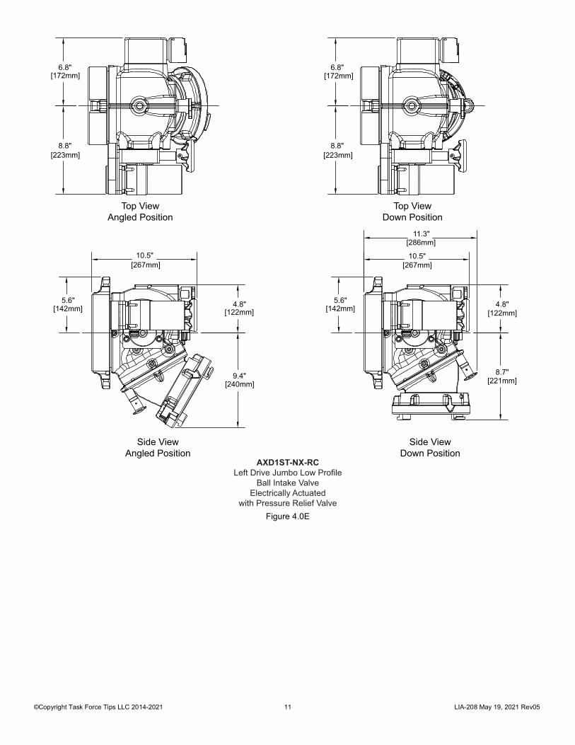
Figure 4.0E
Top ViewAngled Position
Top ViewDown Position
6.8" [172mm]
8.8" [223mm]
6.8" [172mm]
8.8" [223mm]
4.8" [122mm]
9.4" [240mm]
10.5" [267mm]
5.6" [142mm]
10.5" [267mm]
11.3" [286mm]
5.6" [142mm] 4.8"
[122mm]
8.7" [221mm]
Side ViewAngled Position
Side ViewDown Position
AXD1ST-NX-RCLeft Drive Jumbo Low Profile
Ball Intake ValveElectrically Actuated
with Pressure Relief Valve
©Copyright Task Force Tips LLC 2014-2021 12 LIA-208 May 19, 2021 Rev05
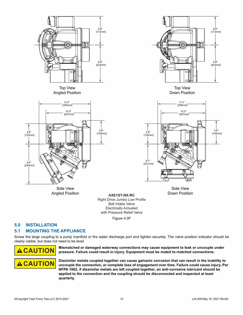
Figure 4.0F
5.0 INSTALLATION5.1 MOUNTING THE APPLIANCEScrew the large coupling to a pump manifold or fire water discharge port and tighten securely. The valve position indicator should beclearly visible, but does not need to be level.
CAUTION Mismatched or damaged waterway connections may cause equipment to leak or uncouple under pressure. Failure could result in injury. Equipment must be mated to matched connections.
CAUTION Dissimilar metals coupled together can cause galvanic corrosion that can result in the inability to uncouple the connection, or complete loss of engagement over time. Failure could cause injury. Per NFPA 1962, if dissimilar metals are left coupled together, an anti-corrosive lubricant should be applied to the connection and the coupling should be disconnected and inspected at least quarterly.
8.8" [223mm]
6.8" [172mm]
8.8" [223mm]
6.8" [172mm]
10.5" [267mm]
12.2" [309mm]
9.4" [240mm]
4.8" [122mm]
5.6" [142mm] 4.8"
[122mm]
8.7" [221mm]
11.3" [286mm]
10.5" [267mm]
5.6" [142mm]
Top ViewAngled Position
Top ViewDown Position
Side ViewAngled Position
Side ViewDown PositionAXE1ST-NX-RC
Right Drive Jumbo Low ProfileBall Intake Valve
Electrically Actuatedwith Pressure Relief Valve
©Copyright Task Force Tips LLC 2014-2021 13 LIA-208 May 19, 2021 Rev05
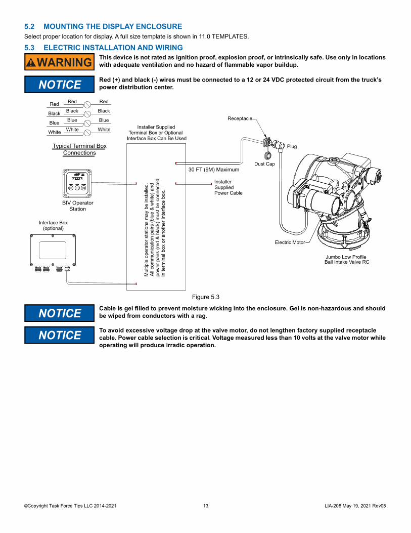
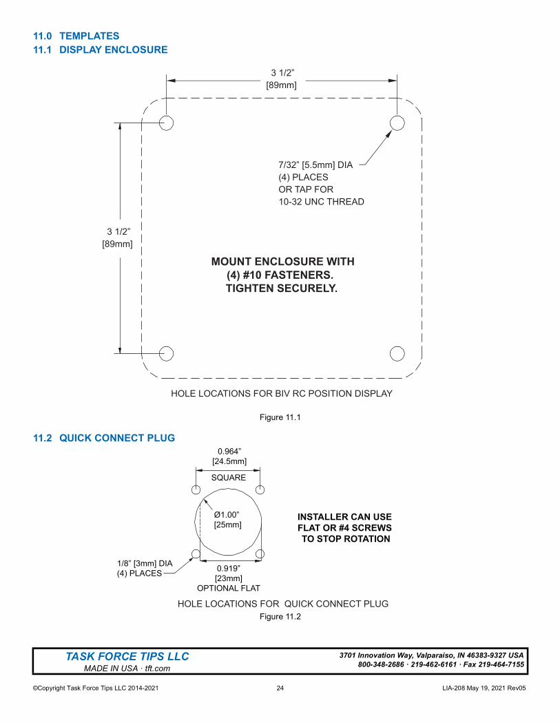
5.2 MOUNTING THE DISPLAY ENCLOSURESelect proper location for display. A full size template is shown in 11.0 TEMPLATES.
5.3 ELECTRIC INSTALLATION AND WIRING
Figure 5.3
WARNING This device is not rated as ignition proof, explosion proof, or intrinsically safe. Use only in locations with adequate ventilation and no hazard of flammable vapor buildup.
NOTICE Red (+) and black (-) wires must be connected to a 12 or 24 VDC protected circuit from the truck’s power distribution center.
NOTICE Cable is gel filled to prevent moisture wicking into the enclosure. Gel is non-hazardous and should be wiped from conductors with a rag.
NOTICE To avoid excessive voltage drop at the valve motor, do not lengthen factory supplied receptacle cable. Power cable selection is critical. Voltage measured less than 10 volts at the valve motor while operating will produce irradic operation.
Electric Motor
Jumbo Low Profile Ball Intake Valve RC
Plug
Dust Cap
Interface Box(optional)
Receptacle
Mul
tiple
ope
rato
r sta
tions
may
be
inst
alle
d.Al
l com
mun
icat
ion
pairs
(blu
e &
whi
te) a
ndpo
wer
pai
rs (r
ed &
bla
ck) m
ust b
e co
nnec
ted
in te
rmin
al b
ox o
r ano
ther
inte
rface
box
.
BIV OperatorStation
Installer SuppliedTerminal Box or Optional
Interface Box Can Be Used
30 FT (9M) Maximum
InstallerSuppliedPower Cable
White
Blue
Black
Red
White
Blue
Black
RedRed
Black
Blue
White
Typical Terminal BoxConnections
©Copyright Task Force Tips LLC 2014-2021 14 LIA-208 May 19, 2021 Rev05
5.3.1 TESTING THE ELECTRICAL INSTALLATIONVERIFY PROPER VOLTAGE
The TFT Ball Intake Valve RC has built in circuit protection to guard against a circumstance where the unit’s movement is blocked beforereaching its full travel limits. Without this circuitry the motor would stall, overheat, and could be permanently damaged.
VOLTAGE TEST
When mechanical installation and electrical connections are complete, perform the following test to verify voltage supply is adequateand the current limiting feature is functioning.
1. Apply power to Valve Control.2. Press OPEN or CLOSE button and hold until valve reaches stop position. Continue to hold button down.3. Once movement is stopped, manually turn override knob in opposite direction while continuing to hold button down. (The override
knob will only turn in one direction.A. If knob can be turned, then voltage supply is adequate.B. If knob can’t be turned and motor continues to operate, the current limit was not reached because the voltage supply or
wiring is not adequate.
SET TRAVEL STOPS
Once proper voltage is verified, perform the following to set the full travel limits:1. Apply power to Valve Control.2. Press CLOSE button and continue to hold until valve is fully closed. Motor must stop by current limit method.
A. If motor continues to operate, see proper voltage test above.3. Press OPEN button and continue to hold until valve is fully open. Motor must stop by current limit method.
A. If motor continues to operate see proper voltage test above.4. Position indicator lights will now track valve movement.
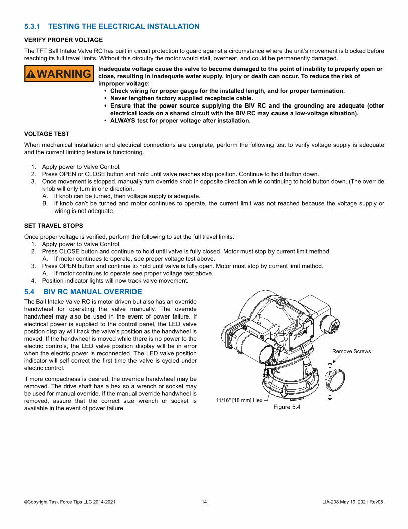
5.4 BIV RC MANUAL OVERRIDEThe Ball Intake Valve RC is motor driven but also has an overridehandwheel for operating the valve manually. The overridehandwheel may also be used in the event of power failure. Ifelectrical power is supplied to the control panel, the LED valveposition display will track the valve’s position as the handwheel ismoved. If the handwheel is moved while there is no power to theelectric controls, the LED valve position display will be in errorwhen the electric power is reconnected. The LED valve positionindicator will self correct the first time the valve is cycled underelectric control.
If more compactness is desired, the override handwheel may beremoved. The drive shaft has a hex so a wrench or socket maybe used for manual override. If the manual override handwheel isremoved, assure that the correct size wrench or socket isavailable in the event of power failure.
WARNING Inadequate voltage cause the valve to become damaged to the point of inability to properly open or close, resulting in inadequate water supply. Injury or death can occur. To reduce the risk of improper voltage:
• Check wiring for proper gauge for the installed length, and for proper termination.• Never lengthen factory supplied receptacle cable.• Ensure that the power source supplying the BIV RC and the grounding are adequate (other
electrical loads on a shared circuit with the BIV RC may cause a low-voltage situation).• ALWAYS test for proper voltage after installation.
11/16" [18 mm] Hex
Remove Screws
Figure 5.4
©Copyright Task Force Tips LLC 2014-2021 15 LIA-208 May 19, 2021 Rev05
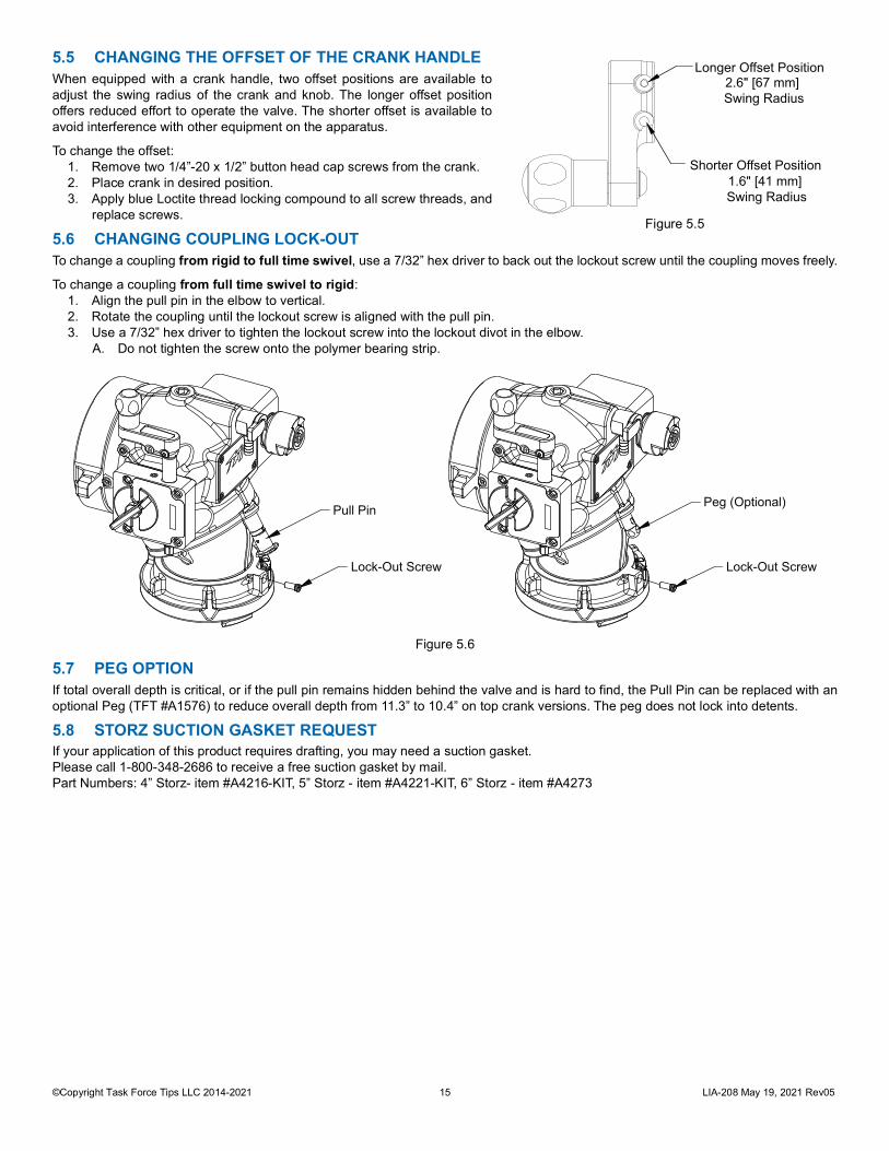
5.5 CHANGING THE OFFSET OF THE CRANK HANDLEWhen equipped with a crank handle, two offset positions are available toadjust the swing radius of the crank and knob. The longer offset positionoffers reduced effort to operate the valve. The shorter offset is available toavoid interference with other equipment on the apparatus.
To change the offset: 1. Remove two 1/4”-20 x 1/2” button head cap screws from the crank. 2. Place crank in desired position. 3. Apply blue Loctite thread locking compound to all screw threads, and
replace screws.
5.6 CHANGING COUPLING LOCK-OUTTo change a coupling from rigid to full time swivel, use a 7/32” hex driver to back out the lockout screw until the coupling moves freely.
To change a coupling from full time swivel to rigid: 1. Align the pull pin in the elbow to vertical. 2. Rotate the coupling until the lockout screw is aligned with the pull pin. 3. Use a 7/32” hex driver to tighten the lockout screw into the lockout divot in the elbow.
A. Do not tighten the screw onto the polymer bearing strip.
Figure 5.6
5.7 PEG OPTIONIf total overall depth is critical, or if the pull pin remains hidden behind the valve and is hard to find, the Pull Pin can be replaced with anoptional Peg (TFT #A1576) to reduce overall depth from 11.3” to 10.4” on top crank versions. The peg does not lock into detents.
5.8 STORZ SUCTION GASKET REQUESTIf your application of this product requires drafting, you may need a suction gasket.Please call 1-800-348-2686 to receive a free suction gasket by mail.Part Numbers: 4” Storz- item #A4216-KIT, 5” Storz - item #A4221-KIT, 6” Storz - item #A4273
Longer Offset Position2.6" [67 mm] Swing Radius
Shorter Offset Position1.6" [41 mm] Swing Radius
Figure 5.5
Lock-Out Screw
Pull Pin
Lock-Out Screw
Peg (Optional)
©Copyright Task Force Tips LLC 2014-2021 16 LIA-208 May 19, 2021 Rev05
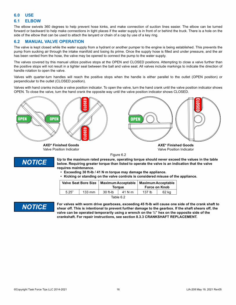
6.0 USE6.1 ELBOWThe elbow swivels 360 degrees to help prevent hose kinks, and make connection of suction lines easier. The elbow can be turnedforward or backward to help make connections in tight places if the water supply is in front of or behind the truck. There is a hole on theside of the elbow that can be used to attach the lanyard or chain of a cap by use of a key ring.
6.2 MANUAL VALVE OPERATIONThe valve is kept closed while the water supply from a hydrant or another pumper to the engine is being established. This prevents thepump from sucking air through the intake manifold and losing its prime. Once the supply hose is filled and under pressure, and the airhas been vented from the hose, the valve may be opened to connect the pump to the water supply.
The valves covered by this manual utilize positive stops at the OPEN and CLOSED positions. Attempting to close a valve further thanthe positive stops will not result in a tighter seal between the ball and valve seat. All valves include markings to indicate the direction ofhandle rotation to open the valve.
Valves with quarter-turn handles will reach the positive stops when the handle is either parallel to the outlet (OPEN position) orperpendicular to the outlet (CLOSED position).
Valves with hand cranks include a valve position indicator. To open the valve, turn the hand crank until the valve position indicator showsOPEN. To close the valve, turn the hand crank the opposite way until the valve position indicator shows CLOSED.
Figure 6.2
Table 6.2
NOTICE Up to the maximum rated pressure, operating torque should never exceed the values in the table below. Requiring greater torque than listed to operate the valve is an indication that the valve requires maintenance.
• Exceeding 30 ft-lb / 41 N·m torque may damage the appliance. • Kicking or standing on the valve controls is considered misuse of the appliance.
Valve Seat Bore Size Maximum Acceptable Torque
Maximum Acceptable Force on Knob
5.25” 133 mm 30 ft-lb 41 N·m 137 lb 62 kg
NOTICE For valves with worm drive gearboxes, exceeding 45 ft-lb will cause one side of the crank shaft to shear off. This is intentional to prevent further damage to the gearbox. If the shaft shears off, the valve can be operated temporarily using a wrench on the ½” hex on the opposite side of the crankshaft. For repair instructions, see section 8.3.3 CRANKSHAFT REPLACEMENT.
OPEN
CLOSEDCLOSED
CLOSED
OPEN OPEN
AXD* Finished GoodsValve Position Indicator
AXE* Finished GoodsValve Position Indicator
©Copyright Task Force Tips LLC 2014-2021 17 LIA-208 May 19, 2021 Rev05
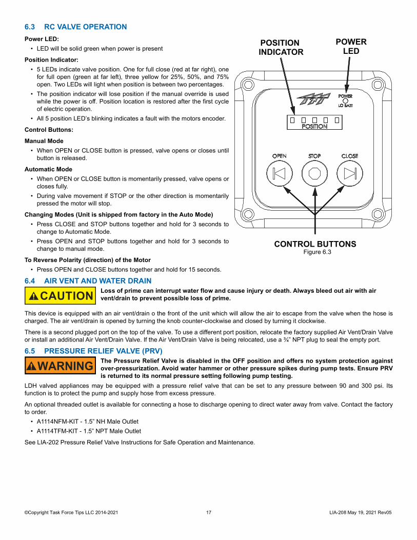
6.3 RC VALVE OPERATIONPower LED:
• LED will be solid green when power is present
Position Indicator:• 5 LEDs indicate valve position. One for full close (red at far right), one
for full open (green at far left), three yellow for 25%, 50%, and 75%open. Two LEDs will light when position is between two percentages.
• The position indicator will lose position if the manual override is usedwhile the power is off. Position location is restored after the first cycleof electric operation.
• All 5 position LED’s blinking indicates a fault with the motors encoder.
Control Buttons:
Manual Mode• When OPEN or CLOSE button is pressed, valve opens or closes until
button is released.
Automatic Mode• When OPEN or CLOSE button is momentarily pressed, valve opens or
closes fully.• During valve movement if STOP or the other direction is momentarily
pressed the motor will stop.
Changing Modes (Unit is shipped from factory in the Auto Mode)• Press CLOSE and STOP buttons together and hold for 3 seconds to
change to Automatic Mode.• Press OPEN and STOP buttons together and hold for 3 seconds to
change to manual mode.
To Reverse Polarity (direction) of the Motor• Press OPEN and CLOSE buttons together and hold for 15 seconds.
6.4 AIR VENT AND WATER DRAIN
This device is equipped with an air vent/drain o the front of the unit which will allow the air to escape from the valve when the hose ischarged. The air vent/drain is opened by turning the knob counter-clockwise and closed by turning it clockwise.
There is a second plugged port on the top of the valve. To use a different port position, relocate the factory supplied Air Vent/Drain Valveor install an additional Air Vent/Drain Valve. If the Air Vent/Drain Valve is being relocated, use a ¾” NPT plug to seal the empty port.
6.5 PRESSURE RELIEF VALVE (PRV)
LDH valved appliances may be equipped with a pressure relief valve that can be set to any pressure between 90 and 300 psi. Itsfunction is to protect the pump and supply hose from excess pressure.
An optional threaded outlet is available for connecting a hose to discharge opening to direct water away from valve. Contact the factoryto order.
• A1114NFM-KIT - 1.5” NH Male Outlet• A1114TFM-KIT - 1.5” NPT Male Outlet
See LIA-202 Pressure Relief Valve Instructions for Safe Operation and Maintenance.
CAUTION Loss of prime can interrupt water flow and cause injury or death. Always bleed out air with airvent/drain to prevent possible loss of prime.
WARNING The Pressure Relief Valve is disabled in the OFF position and offers no system protection againstover-pressurization. Avoid water hammer or other pressure spikes during pump tests. Ensure PRVis returned to its normal pressure setting following pump testing.
POWER LED
POSITION INDICATOR
CONTROL BUTTONSFigure 6.3

©Copyright Task Force Tips LLC 2014-2021 18 LIA-208 May 19, 2021 Rev05
6.5.1 RELIEF VALVE PRESSURE SETTINGTo set the relief valve pressure turn the adjusting screwon the relief valve housing until the surface of the screw iseven with the desired pressure. A 9/16” (14 mm) socketor a 1/4” hex key may be used to turn the adjusting screw.The Pressure relief valve should not be disabled (IE:capped, plugged, or set to the OFF position) for normalservice conditions. Disabling the relief valve may result insystem damage or hose rupture if the system exceedsoperating limits. The pressure relief valve meets therequirements of NFPA 1901.
6.6 PRESSURE LOSS
Figure 6.6
6.7 SUCTION SCREENThis device may be equipped with a suction screen to catch debris larger than 3/8” diameter in the waterway. See the chart to determineadditional loss caused by the screen. To add or replace a suction screen, order TFT part #A1410-KIT.
Figure 6.7
Table 6.5.1
Adjusting Screw
OptionalThreaded Outlet
0
0.1
0.2
0.3
0.4
0.5
0.6
0.7
0.8
0 2000 4000 6000 8000 10000
0
2
4
6
8
10
0 500 1000 1500 2000 2500
FLOW (LPM)
FLOW (GPM)
5 INCH COUPLING
LOSS
(PSI
)
LOSS
(BA
R)
6 INCH COUPLING
0
5
10
15
20
25
30
35
FLOW (GPM)
LOSS
(PSI
)
0
0.5
1
1.5
2
FLOW (L/min)
LOSS
(BA
R)4.5" Waterway
5.0" Waterway
0 1000 2000 3000 4000 5000 6000 7000
0 1000200 400 600 800 1200 1400 1600 1800 2000
©Copyright Task Force Tips LLC 2014-2021 19 LIA-208 May 19, 2021 Rev05
7.0 TEN YEAR EXTENDED WARRANTY FOR JBIV-LP SERIES VALVESTask Force Tips LLC, 3701 Innovation Way, Valparaiso, Indiana 46383-9327 USA (“TFT”) warrants to the original purchaser of its LowProfile Ball Intake Valve (“equipment”), and to anyone to whom it is transferred, that the Low Profile Jumbo Intake Valve series includesa 10 year warranty against manufacturing defects and corrosion affecting the valve’s operational performance.
TFT’s obligation under this warranty is specifically limited to replacing or repairing the equipment (or its parts) which are shown by TFT’sexamination to be in a defective condition attributable to TFT. To qualify for this limited warranty, the claimant must return the equipmentto TFT, at 3701 Innovation Way, Valparaiso, Indiana 46383-9327 USA, within a reasonable time after discovery of the defect. TFT willexamine the equipment. If TFT determines that there is a defect attributable to it, TFT will correct the problem within a reasonable time.If the equipment is covered by this limited warranty, TFT will assume the expenses of repair.
If any defect attributable to TFT under this limited warranty cannot be reasonably cured by repair or replacement, TFT may elect torefund the purchase price of the equipment, less reasonable depreciation, in complete discharge of its obligations under this limitedwarranty. If TFT makes this election, claimant shall return the equipment to TFT free and clear of any liens and encumbrances.
This is a limited warranty. The original purchaser of the equipment, any person to whom it is transferred, and any person who is anintended or unintended beneficiary of the equipment, shall not be entitled to recover from TFT any consequential or incidental damagesfor injury to person and/or property resulting from any defective equipment manufactured or assembled by TFT. It is agreed andunderstood that the price stated for the equipment is in part consideration for limiting TFT’s liability. Some states do not allow theexclusion or limitation of incidental or consequential damages, so the above may not apply to you. TFT shall have no obligation underthis limited warranty if the equipment is, or has been, misused or neglected (including failure to provide reasonable maintenance) or ifthere have been accidents to the equipment or if it has been repaired or altered by someone else.
THIS IS A LIMITED EXPRESS WARRANTY ONLY. TFT EXPRESSLY DISCLAIMS WITH RESPECT TO THE EQUIPMENT ALLIMPLIED WARRANTIES OF MERCHANTABILITY AND ALL IMPLIED WARRANTIES OF FITNESS FOR A PARTICULAR PURPOSE.THERE IS NO WARRANTY OF ANY NATURE MADE BY TFT BEYOND THAT STATED IN THIS DOCUMENT.
This limited warranty gives you specific legal rights, and you may also have other rights which vary from state to state.
©Copyright Task Force Tips LLC 2014-2021 20 LIA-208 May 19, 2021 Rev05
8.0 MAINTENANCETFT products are designed and manufactured to be damage resistant and require minimal maintenance. However, as the primaryfirefighting tool upon which your life depends, it should be treated accordingly. The unit should be kept clean and free of dirt by rinsingwith water after each use. Any inoperable or damaged parts should be repaired or replaced before placing the unit in service. To helpprevent mechanical damage, do not drop or throw equipment. In applications where appliances are left continuously connected to the apparatus or other devices or are used where water is trappedinside the appliance, the appliance must be flushed with fresh water following each use and inspected for damage.This appliance should be disconnected, cleaned and visually inspected inside and out at least quarterly, or as water quality and use mayrequire. Moving parts such as handles, valve ball and couplings should be checked for smooth and free operation. Seals shall begreased as needed with Silicone based grease such as Molykote 112. Any scrapes that expose bare aluminum should be cleaned andtouched up with enamel paint such as Rust-Oleum. Replace any missing or damaged parts before returning to service. Any equipment taken out of service due to failure should be returned to the factory for repair or replacement. If you have any questionsregarding the testing or maintenance of your valve, please call Task Force Tips at 800-348-2686.
8.1 TROUBLESHOOTING
Table 8.1
8.2 SERVICE TESTINGIn accordance with NFPA 1962, equipment must be tested a minimum of annually. Units failing any part of this test must be removedfrom service, repaired and retested upon completion of the repair.
8.3 REPAIRFactory service is available with repair time seldom exceeding one day in our facility. Factory serviced equipment is repaired byexperienced technicians, wet tested to original specifications, and promptly returned. Any returns should include a note as to the natureof the problem and whom to reach in case of questions.
Repair parts and service procedures are available for those wishing to perform their own repairs. Task Force Tips assumes no liability fordamage to equipment or injury to personnel that is a result of user service. Contact the factory or visit the web site at tft.com for partslists, exploded views, test procedures and troubleshooting guides.
Performance tests shall be conducted on the equipment after a repair, or anytime a problem is reported to verify operation in accordancewith TFT test procedures. Consult factory for the procedure that corresponds to the model and serial number of the equipment. Anyequipment which fails the related test criteria should be removed from service immediately. Troubleshooting guides are available witheach test procedure or equipment can be returned to the factory for service and testing.
SYMPTOM POSSIBLE CAUSE REMEDYLeaks Debris or damage in seal area Clean out debris and/or replace damaged partsBinding, Erratic Operation Low voltage (see below) See BelowPower LED on but no operation Low voltage due to:
• wire gauge too small• wire length too long• poor connection• inadequate apparatus electrical
system
Check connections and wiring See Section 5.3.1 on page 14.
LED D6 on motor board blinks rapidly when button is pressed
Loose encoder connection Replace motor subassemblyBad motor encoder Replace motor subassembly
No power LED Polarity reversed or poor connection Check wiring and correct polarityOPEN & CLOSE LED blink every 4 seconds
No communication with Valve Motor Check Blue and White communication wiring
WARNING Service technicians bear responsibility for ensuring use of appropriate protective clothing andequipment. The chosen protective clothing and equipment must provide protection from potentialhazards users may encounter while servicing equipment. Requirements for protective clothing andequipment are determined by the Authority Having Jurisdiction (AHJ).
CAUTION Any alterations to the product or its markings could diminish safety and constitutes a misuse of this product.
NOTICE All replacement parts must be obtained from the manufacturer to assure proper operation of the device.
©Copyright Task Force Tips LLC 2014-2021 21 LIA-208 May 19, 2021 Rev05
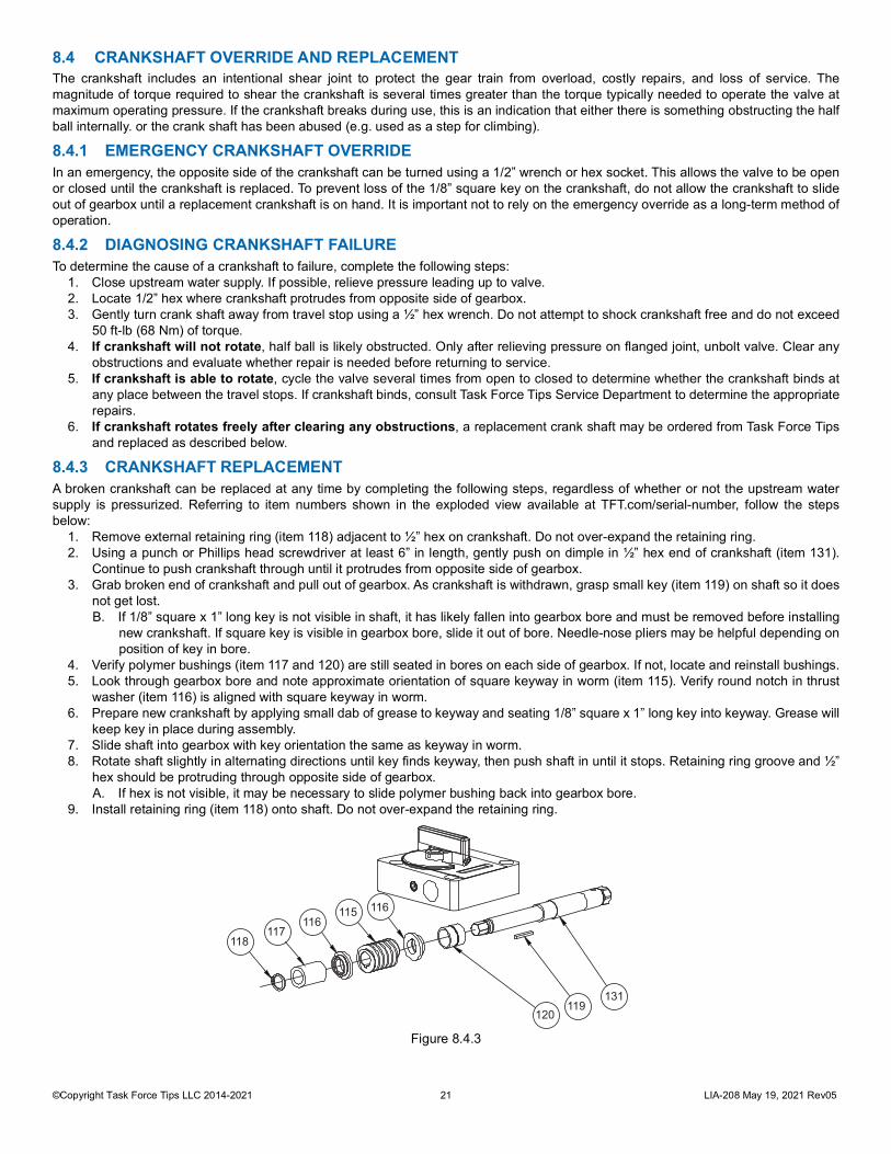
8.4 CRANKSHAFT OVERRIDE AND REPLACEMENTThe crankshaft includes an intentional shear joint to protect the gear train from overload, costly repairs, and loss of service. Themagnitude of torque required to shear the crankshaft is several times greater than the torque typically needed to operate the valve atmaximum operating pressure. If the crankshaft breaks during use, this is an indication that either there is something obstructing the halfball internally. or the crank shaft has been abused (e.g. used as a step for climbing).
8.4.1 EMERGENCY CRANKSHAFT OVERRIDEIn an emergency, the opposite side of the crankshaft can be turned using a 1/2” wrench or hex socket. This allows the valve to be openor closed until the crankshaft is replaced. To prevent loss of the 1/8” square key on the crankshaft, do not allow the crankshaft to slideout of gearbox until a replacement crankshaft is on hand. It is important not to rely on the emergency override as a long-term method ofoperation.
8.4.2 DIAGNOSING CRANKSHAFT FAILURETo determine the cause of a crankshaft to failure, complete the following steps:
1. Close upstream water supply. If possible, relieve pressure leading up to valve.2. Locate 1/2” hex where crankshaft protrudes from opposite side of gearbox.3. Gently turn crank shaft away from travel stop using a ½” hex wrench. Do not attempt to shock crankshaft free and do not exceed
50 ft-lb (68 Nm) of torque.4. If crankshaft will not rotate, half ball is likely obstructed. Only after relieving pressure on flanged joint, unbolt valve. Clear any
obstructions and evaluate whether repair is needed before returning to service.5. If crankshaft is able to rotate, cycle the valve several times from open to closed to determine whether the crankshaft binds at
any place between the travel stops. If crankshaft binds, consult Task Force Tips Service Department to determine the appropriaterepairs.
6. If crankshaft rotates freely after clearing any obstructions, a replacement crank shaft may be ordered from Task Force Tipsand replaced as described below.
8.4.3 CRANKSHAFT REPLACEMENTA broken crankshaft can be replaced at any time by completing the following steps, regardless of whether or not the upstream watersupply is pressurized. Referring to item numbers shown in the exploded view available at TFT.com/serial-number, follow the stepsbelow:
1. Remove external retaining ring (item 118) adjacent to ½” hex on crankshaft. Do not over-expand the retaining ring.2. Using a punch or Phillips head screwdriver at least 6” in length, gently push on dimple in ½” hex end of crankshaft (item 131).
Continue to push crankshaft through until it protrudes from opposite side of gearbox.3. Grab broken end of crankshaft and pull out of gearbox. As crankshaft is withdrawn, grasp small key (item 119) on shaft so it does
not get lost.B. If 1/8” square x 1” long key is not visible in shaft, it has likely fallen into gearbox bore and must be removed before installing
new crankshaft. If square key is visible in gearbox bore, slide it out of bore. Needle-nose pliers may be helpful depending onposition of key in bore.
4. Verify polymer bushings (item 117 and 120) are still seated in bores on each side of gearbox. If not, locate and reinstall bushings.5. Look through gearbox bore and note approximate orientation of square keyway in worm (item 115). Verify round notch in thrust
washer (item 116) is aligned with square keyway in worm.6. Prepare new crankshaft by applying small dab of grease to keyway and seating 1/8” square x 1” long key into keyway. Grease will
keep key in place during assembly.7. Slide shaft into gearbox with key orientation the same as keyway in worm. 8. Rotate shaft slightly in alternating directions until key finds keyway, then push shaft in until it stops. Retaining ring groove and ½”
hex should be protruding through opposite side of gearbox. A. If hex is not visible, it may be necessary to slide polymer bushing back into gearbox bore.
9. Install retaining ring (item 118) onto shaft. Do not over-expand the retaining ring.
Figure 8.4.3
115116
117118
120119
131
116

©Copyright Task Force Tips LLC 2014-2021 22 LIA-208 May 19, 2021 Rev05
9.0 EXPLODED VIEW AND PARTS LISTSExploded views and part lists are available at tft.com/serial-number.
10.0 OPERATION AND INSPECTION CHECKLISTBEFORE EACH USE, equipment must be inspected to this checklist:
1. All valves open and close fully and smoothly.2. Waterway is clear of obstructions.3. There is no damage to any thread or other connection.4. All locks and hold-down devices work properly.5. The pressure setting on the relief valve (if so equipped) is set correctly.6. Gaskets are in good condition.7. There is no obvious damage such as missing, broken or loose parts.8. There is no damage to the appliance (e.g. dents, cracks, corrosion, or other defects that could impair operation).9. All swiveling elements rotate freely.
10. There is no corrosion on any surface.11. There are no missing, worn out or broken lugs on couplings.12. Hose is securely attached.
BEFORE BEING PLACED BACK IN SERVICE, equipment must be inspected to this list:1. All valves open and close smoothly and fully.2. The waterway is clear of obstructions.3. There is no damage to any thread or other type connection.4. The pressure setting on the relief valve (if so equipped) is set correctly.5. All locks and hold-down devices work properly.6. Internal gaskets are in good condition7. There is no damage to the appliance (e.g., dents, cracks, corrosion, or other defects that could impair operation).8. All swiveling connections rotate freely.9. There are no missing parts or components.
10. The marking for maximum operating pressure is visible.11. There are no missing, broken, or worn lugs on couplings.
WARNING Equipment failing any part of the checklist is unsafe for use and must have the problem corrected before use or being placed back into service. Operating equipment that has failed the checklist is a misuse of this equipment.

©Copyright Task Force Tips LLC 2014-2021 23 LIA-208 May 19, 2021 Rev05
This page intentionally left blank.
©Copyright Task Force Tips LLC 2014-2021 24 LIA-208 May 19, 2021 Rev05
TASK FORCE TIPS LLCMADE IN USA · tft.com
3701 Innovation Way, Valparaiso, IN 46383-9327 USA800-348-2686 · 219-462-6161 · Fax 219-464-7155
11.0 TEMPLATES11.1 DISPLAY ENCLOSURE
Figure 11.1
11.2 QUICK CONNECT PLUG
Figure 11.2
HOLE LOCATIONS FOR BIV RC POSITION DISPLAY
7/32” [5.5mm] DIA(4) PLACES OR TAP FOR 10-32 UNC THREAD
3 1/2”[89mm]
3 1/2”[89mm]
MOUNT ENCLOSURE WITH (4) #10 FASTENERS. TIGHTEN SECURELY.
HOLE LOCATIONS FOR QUICK CONNECT PLUG
Ø1.00”[25mm]
1/8” [3mm] DIA(4) PLACES 0.919”
[23mm]OPTIONAL FLAT
INSTALLER CAN USE FLAT OR #4 SCREWS TO STOP ROTATION
0.964”[24.5mm]
SQUARE