Embed Size (px)
Citation preview
G-Code Interpreter For MultiFlex Motion Controllers
Reference Manual Revision 0.3b
Precision MicroControl Corporation 2075-N Corte del Nogal
Carlsbad, CA 92009 * USA
Tel: +1-760-930-0101 Fax: +1-760-930-0222
www.pmccorp.com
Information: [email protected] Technical Support: [email protected]

Limited WARRANTY All products manufactured by Precision MicroControl Corporation (PMC) are guaranteed to be free from defects in material and workmanship, for a period of five years from the date of shipment. Liability is limited to FOB Factory repair, or replacement, of the product. Other products supplied as part of the system carry the warranty of the manufacturer. Precision MicroControl Corporation does not assume any liability for improper use or installation or consequential damage. © Copyright Precision MicroControl Corporation, 2005. All rights reserved. Information in this document is subject to change without notice. Intel is a registered trademark of Intel Corporation. Fanuc is a registered trademark of Fanuc USA Corporation. Microsoft and Windows are registered trademarks of Microsoft Corporation. Acrobat and Acrobat Reader are registered trademarks of Adobe Corporation.
i
Precision MicroControl Corp. 2075-N Corte del Nogal Carlsbad, CA 92009-1415 Tel: +1-760-930-0101 Fax: +1-760-930-0222 Web: www.pmccorp.com Email: Information: [email protected] Technical support: [email protected] Sales: [email protected]

Table of Contents 1.0 Introduction...........................................................................................................................................................1 1.1 Installation .............................................................................................................................................. 2 2.0 G-code Interpreter Operation ................................................................................................................. 3 3.0 G-code Interpreter Commands............................................................................................................... 4 3.1 Run Commands .................................................................................................................................... 4 3.2 Control Commands ............................................................................................................................... 4 3.3 Reporting Commands ........................................................................................................................... 5 3.4 File Loading Commands ....................................................................................................................... 5 4.0 Part Programs ........................................................................................................................................ 6 4.1 Main Program and Subprograms .......................................................................................................... 7 4.2 Macros................................................................................................................................................... 8 4.3 Variables ............................................................................................................................................... 9 4.4 Arithmetic Expressions........................................................................................................................ 10 4.5 Canned Cycles .................................................................................................................................... 12 4.5 Control Commands ............................................................................................................................. 13 4.6 Chopping Function .............................................................................................................................. 14 Appendix A Part Program Format ............................................................................................................ 15 Appendix B Configuration Commands ..................................................................................................... 20 Appendix C Work Coordinate Initialization File ........................................................................................ 26 Appendix D Tool Data Initialization File.................................................................................................... 27
Document Revision History Rev Date Changes 0.1a 3/28/05 Initial Release 0.2a 3/30/05 Added "Control Blocks" section, additional system variables 0.3a 8/02/05 Added Grinder machine type, added A, B, and C auxiliary axes 0.3b 3/20/12 Updated PMC contact information
i

1.0 Introduction MultiFlex Motion Controllers have microprocessors and firmware that provides sophisticated motion functions. Included in MultiFlex firmware versions 4.0 and later is the capability of storing and executing motion programs written in G-codes. This is the industry standard machine tool language used to program machine tools running under Computer Numerical Control (CNC). It is also referred to as the EIA-274 specification. This document provides information necessary to configure and operate the G-code Interpreter on MultiFlex Motion Controllers and serves as a reference for writing motion programs using G-codes.
1
1.1 Installation All MultiFlex Motion Controller firmware revisions starting with 4.0 include the G-code interpreter feature. To verify the revision of firmware running on your controller, start the "Win Control" terminal emulator program that is installed on the PC with PMC's Motion Control API software. This program issues "VE" command to the controller on start up, which prompts the controller for the installed firmware revision. The controller responds by displaying information about the controller model and the firmware currently installed on it. Example of the controller's response to a 'VE' command:
MFX-PCI1440-3-A Motion Controller Hardware: 16384K Private RAM, 512K Flash Memory System Firmware Ver. PM1 Rev. 4.0a Copyright (c) 2002-2012 Precision MicroControl Corporation All rights reserved.
If the firmware revision number reported is below 4.0, the controller's firmware needs to be updated. Visit the support pages on the PMC website at http://www.pmccorp.com/support.php to download the latest firmware files.
2

2.0 G-code Interpreter Operation There are two methods of running part programs on a MultiFlex motion controller that has the G-code Interpreter feature installed. In the first method, Motion Control Command Language (MCCL) commands can be issued to the controller which enable it to accept configuration commands or part programs over the ASCII command interface, and execute them as they are received. In the second method, configuration commands and part programs are stored in files on the controller, and then commands are issued to the controller to cause it to process the data in the files. These two methods can be used interchangeably for configuration of the controller and execution of part programs. To define the machine setup, the user can issue the Run Configuration Enable (RCE) command and then send Configuration commands to the controller. The supported configuration commands are listed in an appendix of this manual. The controller will interpret the commands as they are received and initialize internal configuration variables. After sending all the configuration commands, the End-Of-File ASCII character (1A hex) is sent to cause the controller to return to normal MCCL command processing. If the configuration commands are stored in a text file on the host computer, the Win Control program can be used to send them to the controller. To do this start the Win Control program and issue the "RCE" command and then use the "Open..." option in the Win Control File menu to locate and load the file containing the configuration commands. As an alternative method to defining the machine setup, the configuration commands can be stored in a file on the controller. This can be done with the Win Control program using the "ALO" command. The parameter to the LO command is the file number use to store the configuration file. The Run Configuration File (RCF) command can then be issued to the controller to cause it to process the file and initialize the internal variables. The parameter to the RCF command is the file number that the configuration commands have been stored in. Two types of initialization files are used for setting up work coordinates and tool data on the controller. These files can be sent to the controller and processed immediately, or stored on the controller and processed with file commands. The Work Coordinate Initialization File contains offsets for work coordinate systems that can be used during part program execution. The Run Work Coordinate Enable (RWE) and Run Work Coordinate File (RWF) commands are used to load this data. The Tool Data Initialization File defines the geometry of tools and is used for tool offsets and compensation while running part programs. The Run Tool Data Enable (RTE) and Run Tool Data File (RTF) commands are used to load this data on the controller. Appendices of this manual describe the required format of the Work Coordinate and Tool Data Initialization Files. After the G-code interpreter setup is completed, the user can issue the Run Part Program Enable (RUE) command and send the part program to the controller in >real time=. In this method, the controller will accept the part program from the command interface and execute it immediately (after filling internal queues). This requires that the host computer be programmed to download the part program to the controller as fast as it will accept it. After sending the entire part program, the End-Of-File ASCII character (1A hex) is sent to cause the controller to return to normal MCCL command processing. If the part program is stored in a text file on the host computer, the Win Control program can be used to send it to the controller. To do this start the Win Control program and issue the @RUE@ command and then use the AOpen...@ option in the Win Control File menu to locate and load the part program file. Alternatively, the user has the option of loading a part program into the controller's file system and issuing the Run Part Program File (RUF) command with the file number as the command parameter. This method has the advantage of freeing the host computer from being required for part program execution. With this method, by issuing the RUF command as a background task, the controller will be able to accept other commands from the host computer, while it processes the part program. The G-code Interpreter Commands (described later in the manual) are specifically designed for this purpose. When using the RUF command in this way, the RUT command should be used to terminate the background task.
3

3.0 G-code Interpreter Commands The G-code Interpreter feature of the MultiFlex Motion Controller includes MCCL commands that facilitate running part programs. Note that these commands have 3 letter mnemonics, while the standard motion commands all have 2 letter mnemonics. Other than this difference, the G-code Interpreter commands can be used in the same manner as the motion commands. 3.1 Run Commands RUE Run Part Program Enable (n = -1,0,1) RCE Run Configuration Enable RWE Run Work Coordinate Enable RTE Run Tool Data Enable RUFn Run Part Program File (-127 <= n <= 127) RUT Run Terminate RCFn Run Configuration File (1 <= n <= 127) RWFn Run Work coordinate File (1 <= n <= 127) RTFn Run Tool data File (1 <= n <= 127) 3.2 Control Commands IST Initiate Start IBB Initiate Block by Block IFH Initiate FeedHold EDR Enable Dry Run DDR Disable Dry Run EOS Enable Optional Stop DOS Disable Optional Stop EBS Enable Block Skip DBS Disable Block Skip SFOn Set Feedrate Override (0 <= n) SROn Set Rapid Overrride (0 <= n) SSOn Set Spindle Override (0 <= n)
4

3.3 Reporting Commands DBT Display Block Text (n = 0,1) DEM Display Error Messages (n = 0,1) DFN Display File Number (n = 0,1) DFP Display File Position (n = 0,1) GRS Get Run status TRS Tell Run Status TBP Tell Block file Position TNP Tell Next file Position TPN Tell Program Number TRC Tell Repeat Count TSN Tell Sequence Number TSS Tell Spindle Speed TTN Tell Tool Number 3.4 File Loading Commands LOF Load Fanuc Formatted Part Program This command facilitates loading of Fanuc formatted part programs into the controller's file memory. When the LOF command is issued to the controller, it will accept text with embedded words having 'O' addresses that specify what file number the text is to be stored in. The file should have the following format to be loaded correctly: ONE LINE TEXT LEADER, THIS WILL BE DISCARDED Oaaaa ... Obbbb ... Occcc ... Where aaaa, bbbb and cccc are decimal digits specifying the file number where the succeeding text will be loaded. The valid range for the file numbers are 1 to 127. The End-Of-File ASCII character (1A hex) should not be sent until after all text has been sent to the controller. This will terminate the loading process.
5
4.0 Part Programs The MultiFlex G-code Interpreter is designed to execute user written programs which command the machine axes to follow specific paths. These motions commonly perform machining operations in the manufacture of parts, so the programs are called 'Part Programs'. The G-code Interpreter supports part programs following the EIA-274 specification: Interchangeable Variable Block Data Format for Positioning, Contouring, and Contouring/Positioning Numerically Controlled Machines. A part program consists of lines of text called 'blocks'. Each line or block in the program is separated by a linefeed character (ASCII 10). A block may optionally be terminated with an 'End of Block' (EOB) character. A block can be up to 255 characters in length, including the EOB and linefeed characters. A program can consist of an unlimited number of blocks (within the limits of the controller's file system if storing the program on the controller). Each block is composed of 'words'. A word is defined to be an uppercase alpha character called the 'Address', followed by a numerical value. The Address of each word defines how the associated numerical value is interpreted. The valid addresses and their meanings are listed below: Address Description E Max. Angle Change for Continuous Motion F Feed Function G Preparatory Function H Misc. Function Parameter (integer value) I Interpolation Parameter J Interpolation Parameter K Interpolation Parameter L Repeat Block (integer value between 1 and 9999) M Miscellaneous Function N Sequence Number O Program Number P Misc. Function Parameter (integer value) S Spindle Speed Function T Tool number U U Axis Dimension V V Axis Dimension W W Axis Dimension X X Axis Dimension Y Y Axis Dimension Z Z Axis Dimension The numerical values that follow these addresses may be integers or real numbers with decimal points. If a value appears without a decimal point, it is interpreted as if the decimal point follows the right most digit. The format detail for the G-code Interpreter is as follows:
N4G2X+90Y+90Z+90I+90J+90U+90V+90W+90F50S50T2M2H5E4* This indicates that the sequence number contains up to 4 digits, the preparatory function code up to 2 digits, each of the dimension values have up to 9 digits (with optional decimal point), the feed and spindle speed functions each have up to 5 digits (with optional decimal points), and the tool, miscellaneous, parameter and repeat functions have up to 2, 2, 5 and 4 digits respectively. A sequence number is a word beginning with the 'N' address followed by an integer. They may be used to identify specific blocks in the program. If a block contains a sequence number, it should be the first word in the block, and have a value distinct from all other block sequence numbers. If a block is the destination of a program jump or call, it must include a sequence number word.
6
4.1 Main Program and Subprograms When the Run Part Program File (RUF) command is issued to the controller, the parameter to the command must specify a part program that is resident in the controller's file system. This starting part program is referred to as the 'Main' program. Block execution will start with the first block in the file, and continue until either the M02 or M30 miscellaneous function code is encountered. These codes will cause the execution to stop. There is no difference in how these two codes operate. It is possible for the main program to cause another part program to be executed from the file system. This is done by placing M98 in a block along with a P word specifying the number of another part program in the controller's file system. Execution of the main program will be paused and the execution of the specified subprogram will commence. When the subprogram completes its task, it should call M99 to terminate execution of the subprogram and resume execution of the main program at the block following the block that contained the subprogram call. If the block in the subprogram containing M99 also contains a 'P word', execution will resume with the main program, but at the block with a sequence number specified by the P word value. If the block which calls a subprogram includes an 'L word', the subprogram will be executed multiple times. The number of times is specified by the L word value. It is acceptable for a subprogram to call another subprogram by using the M98 code. The block in the subprogram which contains M98 must also include a P word specifying another (or the same) subprogram. It may also include a L word specifying the number of times that subprogram should be executed. Each time a subprogram is called, data for the current part program is saved in an internal memory stack. That stack has room to store the data for 3 programs. This means that the G-code Interpreter will allow subprogram calls to be nested up to 3 levels deep. If the main program includes a block with a M99 code, the part program execution will jump to the beginning of the main program and continue. If the block containing M99 also includes a P word, program execution will jump to the block in the main program that contains the sequence number specified by the P value.
7
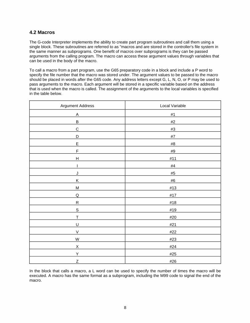
4.2 Macros The G-code Interpreter implements the ability to create part program subroutines and call them using a single block. These subroutines are referred to as "macros and are stored in the controller's file system in the same manner as subprograms. One benefit of macros over subprograms is they can be passed arguments from the calling program. The macro can access these argument values through variables that can be used in the body of the macro. To call a macro from a part program, use the G65 preparatory code in a block and include a P word to specify the file number that the macro was stored under. The argument values to be passed to the macro should be placed in words after the G65 code. Any address letters except G, L, N, O, or P may be used to pass arguments to the macro. Each argument will be stored in a specific variable based on the address that is used when the macro is called. The assignment of the arguments to the local variables is specified in the table below.
Argument Address
Local Variable
A #1
B #2
C #3
D #7
E #8
F #9
H #11 I #4 J #5
K #6
M #13
Q #17
R #18
S #19
T #20
U #21
V #22
W #23
X #24
Y #25
Z #26 In the block that calls a macro, a L word can be used to specify the number of times the macro will be executed. A macro has the same format as a subprogram, including the M99 code to signal the end of the macro.
8
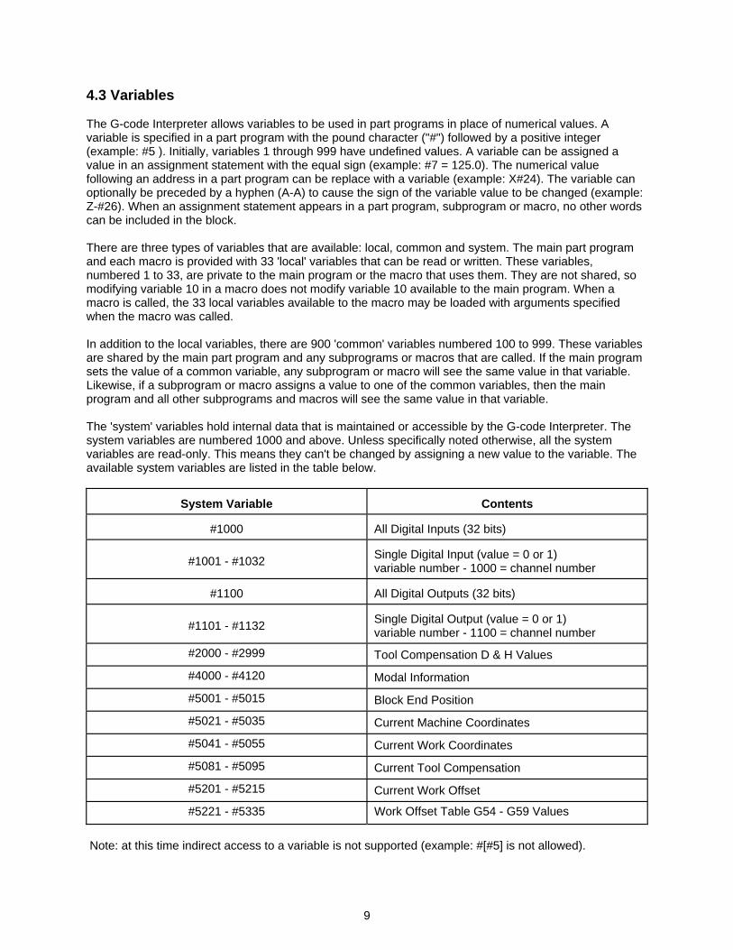
4.3 Variables The G-code Interpreter allows variables to be used in part programs in place of numerical values. A variable is specified in a part program with the pound character ("#") followed by a positive integer (example: #5 ). Initially, variables 1 through 999 have undefined values. A variable can be assigned a value in an assignment statement with the equal sign (example: #7 = 125.0). The numerical value following an address in a part program can be replace with a variable (example: X#24). The variable can optionally be preceded by a hyphen (A-A) to cause the sign of the variable value to be changed (example: Z-#26). When an assignment statement appears in a part program, subprogram or macro, no other words can be included in the block. There are three types of variables that are available: local, common and system. The main part program and each macro is provided with 33 'local' variables that can be read or written. These variables, numbered 1 to 33, are private to the main program or the macro that uses them. They are not shared, so modifying variable 10 in a macro does not modify variable 10 available to the main program. When a macro is called, the 33 local variables available to the macro may be loaded with arguments specified when the macro was called. In addition to the local variables, there are 900 'common' variables numbered 100 to 999. These variables are shared by the main part program and any subprograms or macros that are called. If the main program sets the value of a common variable, any subprogram or macro will see the same value in that variable. Likewise, if a subprogram or macro assigns a value to one of the common variables, then the main program and all other subprograms and macros will see the same value in that variable. The 'system' variables hold internal data that is maintained or accessible by the G-code Interpreter. The system variables are numbered 1000 and above. Unless specifically noted otherwise, all the system variables are read-only. This means they can't be changed by assigning a new value to the variable. The available system variables are listed in the table below.
System Variable
Contents
#1000
All Digital Inputs (32 bits)
#1001 - #1032
Single Digital Input (value = 0 or 1) variable number - 1000 = channel number
#1100
All Digital Outputs (32 bits)
#1101 - #1132
Single Digital Output (value = 0 or 1) variable number - 1100 = channel number
#2000 - #2999 Tool Compensation D & H Values
#4000 - #4120 Modal Information
#5001 - #5015 Block End Position
#5021 - #5035 Current Machine Coordinates
#5041 - #5055 Current Work Coordinates
#5081 - #5095 Current Tool Compensation
#5201 - #5215 Current Work Offset
#5221 - #5335 Work Offset Table G54 - G59 Values
Note: at this time indirect access to a variable is not supported (example: #[#5] is not allowed).
9
4.4 Arithmetic Expressions In the section describing variables, it was shown that an assignment statement can be used to set a variable's value. A more complex arithmetic expression can also be used in a variable assignment statement (example: #25 = #4 / 2 + #5). This allows the value to be calculated at run time using a combination of variables, functions, and numerical constants. An arithmetic expression can also be used in place of a numerical constant after the address character in a part program word. For the expression to be interpreted properly, it must be enclosed in square brackets (example: X[#24 + 1.5] ). The 2 tables below lists the expression operators that are supported.
Addition Operators
Description
+
Addition
-
Subtraction
OR
Bit Wise Logical OR
XOR
Bit Wise Logical Exclusive OR
Multiplication Operators
Description
* Multiplication
/
Division
AND
Bit Wise Logical AND
MOD
Remainder
A function is called by its name followed by the argument in square brackets []. The argument can be a numerical constant, a variable, or an expression (example: #26 = #11 * sin[30]). The table below lists the available functions.
Function Name
Description
SIN
Sine (argument in degrees)
COS
Cosine (argument in degrees)
TAN
Tangent (argument in degrees)
ASIN
Arc Sine
ACOS
Arc Cosine
ATAN
Arc Tangent
SQRT
Square Root
ABS
Absolute value
ROUND
Round to nearest integer
10
11
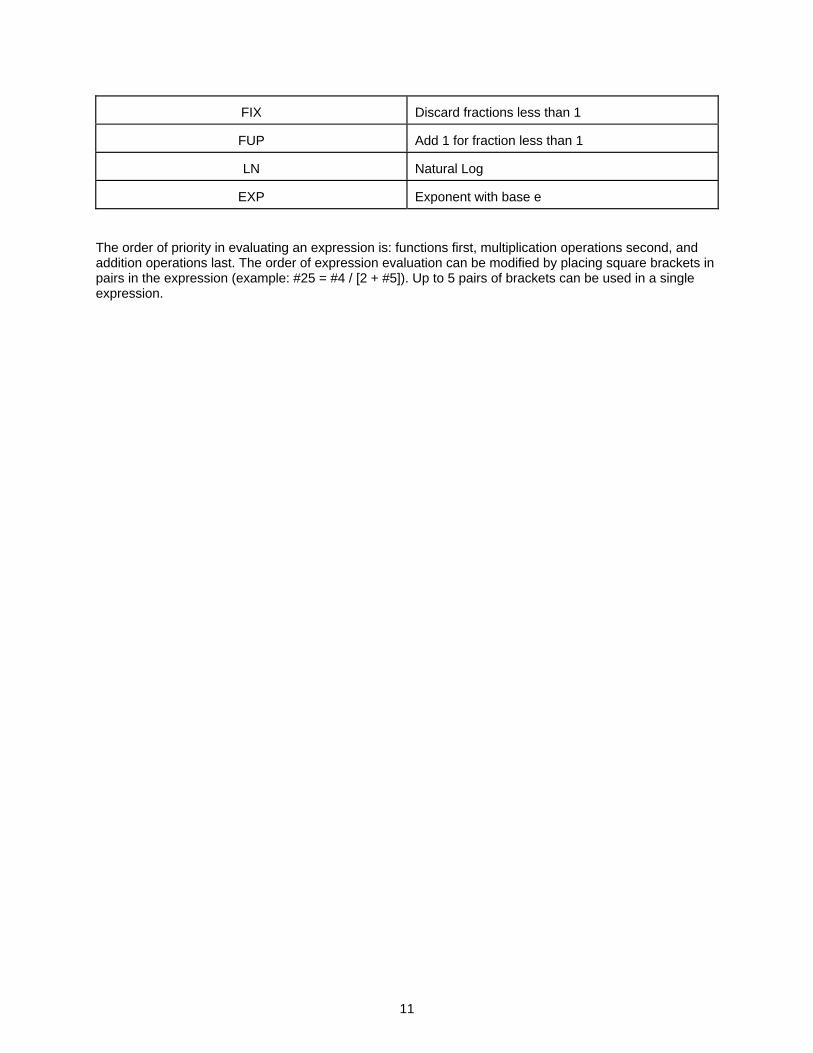
FIX
Discard fractions less than 1
FUP
Add 1 for fraction less than 1
LN
Natural Log
EXP
Exponent with base e
The order of priority in evaluating an expression is: functions first, multiplication operations second, and addition operations last. The order of expression evaluation can be modified by placing square brackets in pairs in the expression (example: #25 = #4 / [2 + #5]). Up to 5 pairs of brackets can be used in a single expression.

4.5 Canned Cycles Similar to macros, the G-code Interpreter implements "canned cycles". these are subroutines that can be called from a single block. There are 8 preparatory codes (G82 - G89) reserved for calling canned cycles. When one of these G-codes appears at the beginning of a block, the respective canned cycle will be executed. The canned cycle subroutines are stored in the controller's file system in the same manner as subprograms. The file numbers that are used when the canned cycles are stored in the controller's file system must match the file numbers specified in the "GxxCANNEDCYCLEFILE" configuration commands. See appendix B for a description of these configuration commands. Like macros, canned cycles allow arguments to be passed from the calling program. The canned cycle can access these argument values through variables that can be used in the body of the canned cycle. The argument values to be passed to the canned cycle should be placed in words after the canned cycle G-code. Any address letters except G, L, N, O, or P may be used to pass arguments to the canned cycle. Each argument will be stored in a specific local variable based on the address that is used when the canned cycle is called. The assignment of the arguments to the local variables is specified in the table below.
Argument Address
Local Variable
A #1
B #2
C #3
D #7
E #8
F #9
H #11
I #4
J #5
K #6
M #13
Q #17
R #18
S #19
T #20
U #21
V #22
W #23
X #24
Y #25
Z #26
In the block that calls a canned cycle, a L word can be used to specify the number of times the canned cycle will be executed. A canned cycle has the same format as a subprogram, including the M99 code to signal the end of the canned cycle.
12

4.6 Control Commands The execution flow of a part program can be modified with a block that contains an If-Then or a While-Do command. The format of a If-Then command is: IF [conditional expression] GOTO n. When the conditional expression is satisfied, program execution jumps to the block with sequence number ‘n’. In an If-Then command, the value ‘n’ must be a constant. Also, the block that contains sequence ‘n’ must be in the same program, subprogram or macro as the If-Then block. The following table lists the conditional expressions that can be used.
Conditional Expression
Function
#j EQ #k
= (equal)
#j NE #k
!= (not equal)
#j GT #k
> (greater than)
#j LT #k
< (less than)
#j GE #k
>= (greater than or equal)
#j LE #k
<= (less than or equal)
In the conditional expressions, #j and #k can be a constant, a variable, or an arithmetic expression. If #j or #k is an arithmetic expression, it must be enclosed in square brackets. As an alternative, a block can contain just GOTO n. In this case the execution flow jumps unconditionally to the block with sequence ‘n’. The format of a While-Do commands is: WHILE [conditional expression] DO n ... END n All blocks between the DO and END commands will be executed repeatedly while the conditional expression is true. The value of ‘n’ used after the END command must be the same positive integer that follows the matching DO command. The While-Do and matching End commands may be nested up to 3 levels deep. Each pair of nested While-Do and End commands must have a unique ‘n’ value. An alternative command format is: DO n ... END n In this case, the enclosed blocks are repeated unconditionally.
13
14
4.6 Chopping Function A block with G81 can be used to enable the "chopping Function" for a machine axis. Once this function is enabled, the selected axis will cycle back and forth, while part program execution continues on to succeeding blocks. The motion of the selected axis is independent of motion initiated on the other axes. The cycling will continue until the chopping function is disabled with a G80 preparatory code in the part program. A part program block to enable the chopping function must have the following form: G81 Z___ Q___ R___ F___ In this example, the Z axis was selected as the axis to be enabled. Alternatively, one of the other machine axes could have been selected by replacing the 'Z' address with the respective address letter. The 'R word' specifies the incremental distance between the axes' current position, and the starting position for the cycle motion. The Q word specifies the incremental distance to ending position of the cycle motion (relative to the starting position). The 'F word' specifies the feed-rate that will be used for cycle motion of the axis. When the Chopping Function is enabled, the selected axis will move at the rapid rate to the starting position. It will then cycle between the starting position and the ending position, at the specified feedrate. When the Chopping function is disabled, the selected axis will continue motion until it reaches the starting position before it comes to a stop.
15
Appendix A: Part Program Format A part program consists of 'Blocks' separated by linefeeds. Each block consist of one or more 'Words' and an End-Of-Block character. A word begins with an 'Address' character followed by an integer or real number. The default End-Of-Block character is the new line charcter (ASCII 10 decimal). A typical block has the following form: N001 G01 X2.654 Y-4.623 Z1.0 F40.0 S1000.0 M03 * where: N = sequence number G = preparatory function code X, Y and Z = dimensions F = feed rate S = spindle rate M = miscellaneous function code * = represents End-of-Block character Additional notes on part programs: 1. Sequence numbers are optional, but when include must be no more than 4 digits with a value greater
then 0 (ex. N115). 2. G,M and T codes must be no more than 2 digits (eg. G1 or G01). 3. Multiple G codes can be included in a single block. 4. Only one M code can occur in a single block. 5. Arcs (G02 & G03) must be specified as ending coordinates (X, Y and Z) and center coordinates (I, J
and K). The ending coordinates can be specified with absolute or incremental dimensions, by default the center coordinates are interpreted as incremental dimensions (relative to the starting point).
6. Spaces are optional between words of the block. 7. The Block Deleter character '/' can be placed anywhere in a block. Any characters preceded by the '/'
character will be skipped during part program execution if Block Skip is enabled. 8. Comments in the part program are delimited by open and close parenthesis: >(> and >=)=. For a complete description of the G-code language, refer to the Electronics Industry Association specification EIA-274 and CNC text books.

Appendix A: Part Program Format (continued)
16
Address Characters Address Description A A Axis Dimension B B Axis Dimension C C Axis Dimension D Macro Parameter (integer value) E Max. Angle Change for Continuous Motion F Feed Function G Preparatory Function H Misc. Function Parameter (integer value) I Interpolation Parameter J Interpolation Parameter K Interpolation Parameter L Repeat Block (integer value between 1 and 9999) M Miscellaneous Function N Sequence Number O Program Number P Misc. Function Parameter (integer value) Q Macro Parameter R Macro Parameter S Spindle Speed Function T Tool number U U Axis Dimension V V Axis Dimension W W Axis Dimension X X Axis Dimension Y Y Axis Dimension Z Z Axis Dimension G-Codes A preparatory function is a word beginning with the 'G' address followed by a 2 digit integer. These codes cause the controller to enter certain control modes. The following is a list of available G codes: Code Description G00 Point to point positioning at rapid rate G01 Linear interpolation at feed rate G02 Circular Contour, clockwise at feed rate G03 Circular Contour, counter-clockwise at feed rate G04 Dwell, delays program execution, period specified in seconds with X word G17 XY Plane Selection G18 ZX Plane Selection G19 YZ Plane Selection G20 Inch Programming (for Fanuc compatibility) G21 Metric Programming (for Fanuc compatibility) G40 Cutter Radius Compensation Cancel
Appendix A: Part Program Format (continued)
17
G41 Cutter Radius Compensation Left G42 Cutter Radius Compensation Right G43 Tool Length Compensation Plus G44 Tool Length Compensation Minus G45 Tool Offset Increase G46 Tool Offset Decrease G47 Tool Offset Double Increase G48 Tool Offset Double Decrease G49 Tool Length Compensation Cancel G52 Local Coordinate System Set G53 Machine Coordinate System Select G54 Work Coordinate System 1 Select G55 Work Coordinate System 2 Select G56 Work Coordinate System 3 Select G57 Work Coordinate System 4 Select G58 Work Coordinate System 5 Select G59 Work Coordinate System 6 Select G65 Macro Call G66 Macro Modal Call G67 Macro Modal Call Cancel G70 Inch Programming (EIA-274 standard) G71 Metric Programming (EIA-274 standard) G80 Chopping Function Cancel G81 Chopping Function G82-G89 Canned Cycles (machine dependent, implemented as macros) G90 Absolute Dimension Input G91 Incremental Dimension Input G92 Work Coordinate Change
Appendix A: Part Program Format (continued)
18
M-Codes A miscellaneous function is a word beginning with the 'M' address followed by a 2 digit number from 0 to 99. These codes cause the controller to perform predefined and user defined auxiliary functions. The following is a list of M codes that have predefined functions: Code Description M00 Program Stop M02 End of Program M03 Spindle Clockwise M04 Spindle Counter-Clockwise M05 Spindle Off M06 Tool Change M30 End of Data M98 Sub Program Call (destination specified in P word, max. 10 levels of nesting) M99 Sub Program Return All of the miscellaneous function codes (except M98 and M99) can be setup to perform user defined operations when they are executed by the controller. The G-code Interpreter will call the associated controller's MCCL macro whenever it encounters one of these M-codes. The MCCL macro that is called is determined by adding the M code number to the "Base Miscellaneous Function Macro" number. Since the Base Miscellaneous Function Macro number is 1000 by default, M03 will cause MCCL macro number 1003 to be called. M06 is a special case. Since it is used to change or select a tool, the G-code Interpreter will load the tool number set by the T word into the controller's User Register 0 prior to calling the corresponding MCCL macro. The commands in the MCCL macro can read the contents of the user register in order to select the appropriate tool. The MCCL macros that these codes cause to be called, should be defined prior to running the part program. This can be done by downloading command files containing macro define statements to the motion controller with the Win Control program.
Appendix A: Part Program Format (continued)
19
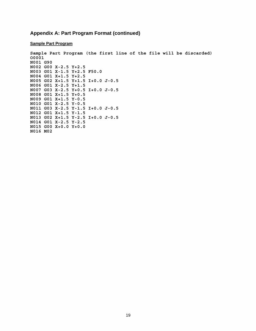
Sample Part Program Sample Part Program (the first line of the file will be discarded) O0001 N001 G90 N002 G00 X-2.5 Y+2.5 N003 G01 X-1.5 Y+2.5 F50.0 N004 G01 X+1.5 Y+2.5 N005 G02 X+1.5 Y+1.5 I+0.0 J-0.5 N006 G01 X-2.5 Y+1.5 N007 G03 X-2.5 Y+0.5 I+0.0 J-0.5 N008 G01 X+1.5 Y+0.5 N009 G01 X+1.5 Y-0.5 N010 G01 X-2.5 Y-0.5 N011 G03 X-2.5 Y-1.5 I+0.0 J-0.5 N012 G01 X+1.5 Y-1.5 N013 G02 X+1.5 Y-2.5 I+0.0 J-0.5 N014 G01 X-2.5 Y-2.5 N015 G00 X+0.0 Y+0.0 N016 M02
20
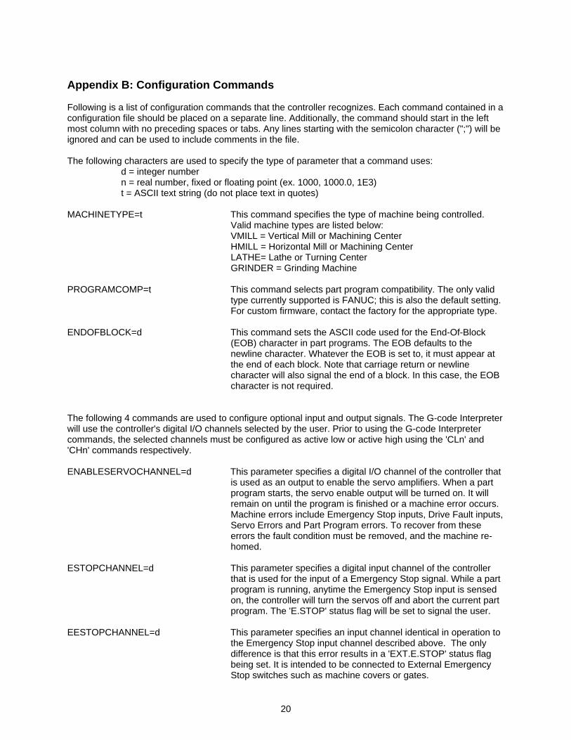
Appendix B: Configuration Commands Following is a list of configuration commands that the controller recognizes. Each command contained in a configuration file should be placed on a separate line. Additionally, the command should start in the left most column with no preceding spaces or tabs. Any lines starting with the semicolon character (";") will be ignored and can be used to include comments in the file. The following characters are used to specify the type of parameter that a command uses:
d = integer number n = real number, fixed or floating point (ex. 1000, 1000.0, 1E3) t = ASCII text string (do not place text in quotes)
MACHINETYPE=t This command specifies the type of machine being controlled.
Valid machine types are listed below: VMILL = Vertical Mill or Machining Center HMILL = Horizontal Mill or Machining Center LATHE= Lathe or Turning Center GRINDER = Grinding Machine
PROGRAMCOMP=t This command selects part program compatibility. The only valid
type currently supported is FANUC; this is also the default setting. For custom firmware, contact the factory for the appropriate type.
ENDOFBLOCK=d This command sets the ASCII code used for the End-Of-Block
(EOB) character in part programs. The EOB defaults to the newline character. Whatever the EOB is set to, it must appear at the end of each block. Note that carriage return or newline character will also signal the end of a block. In this case, the EOB character is not required.
The following 4 commands are used to configure optional input and output signals. The G-code Interpreter will use the controller's digital I/O channels selected by the user. Prior to using the G-code Interpreter commands, the selected channels must be configured as active low or active high using the 'CLn' and 'CHn' commands respectively. ENABLESERVOCHANNEL=d This parameter specifies a digital I/O channel of the controller that
is used as an output to enable the servo amplifiers. When a part program starts, the servo enable output will be turned on. It will remain on until the program is finished or a machine error occurs. Machine errors include Emergency Stop inputs, Drive Fault inputs, Servo Errors and Part Program errors. To recover from these errors the fault condition must be removed, and the machine re-homed.
ESTOPCHANNEL=d This parameter specifies a digital input channel of the controller
that is used for the input of a Emergency Stop signal. While a part program is running, anytime the Emergency Stop input is sensed on, the controller will turn the servos off and abort the current part program. The 'E.STOP' status flag will be set to signal the user.
EESTOPCHANNEL=d This parameter specifies an input channel identical in operation to
the Emergency Stop input channel described above. The only difference is that this error results in a 'EXT.E.STOP' status flag being set. It is intended to be connected to External Emergency Stop switches such as machine covers or gates.

Appendix B: Configuration Commands (continued)
21
DRIVEFAULTCHANNEL=d This parameter specifies an input channel to be used to monitor a
drive fault signal from the servo amplifiers. This channel will operate similar to the Emergency Stop channel described above. When this input is on, the 'DRIVE FAULT' status flag will be set.
BASEMISCFUNCMACRO=d This parameter specifies the range of controller's MCCL macros
that will be called whenever a M code is executed as part of a part program. The default value for this parameter is 1000. This implies that when M03 is present in a part program and executed, macro number 1003 on the controller will be executed.
M06 is a special case because it is normally used for tool changes. When the macro corresponding to M06 is called on the controller, the tool number set with the T word will be placed in the controller's user register 0. The macro commands can read the desired tool number from this register and retrieve the appropriate tool.
AUXILIARYFUNCMACRO=d This parameter specifies an MCCL macro that will be called if a
part program block contains a B word. The integer value in the B word will be placed in the controller's user register 0 prior to calling the macro. The default auxiliary function macro is 1099.
G82CANNEDCYCLEFILE=d This parameter specifies the file number where the G82 canned
cycle is stored. G83CANNEDCYCLEFILE=d Same as above, except for the G83 canned cycle. G84CANNEDCYCLEFILE=d Same as above, except for the G84 canned cycle. G85CANNEDCYCLEFILE=d Same as above, except for the G85 canned cycle. G86CANNEDCYCLEFILE=d Same as above, except for the G86 canned cycle. G87CANNEDCYCLEFILE=d Same as above, except for the G87 canned cycle. G88CANNEDCYCLEFILE=d Same as above, except for the G88 canned cycle. G89CANNEDCYCLEFILE=d Same as above, except for the G89 canned cycle. XAXIS=d Specifies the axis number of the motor to be assigned as the X
axis (Default is axis 1). The axis number is determined by the connection of the motor to the controller. The logical number of the axis on the controller board is the number that should used in this parameter.
YAXIS=d Specifies the axis number of the motor to be assigned as the Y
axis (Default is axis 2). ZAXIS=d Specifies the axis number of the motor to be assigned as the Z
axis (Default is no axis). AAXIS=d Specifies the axis number of the motor to be assigned as the A
axis (Default is no axis). BAXIS=d Specifies the axis number of the motor to be assigned as the B
axis (Default is no axis). CAXIS=d Specifies the axis number of the motor to be assigned as the C
axis (Default is no axis).
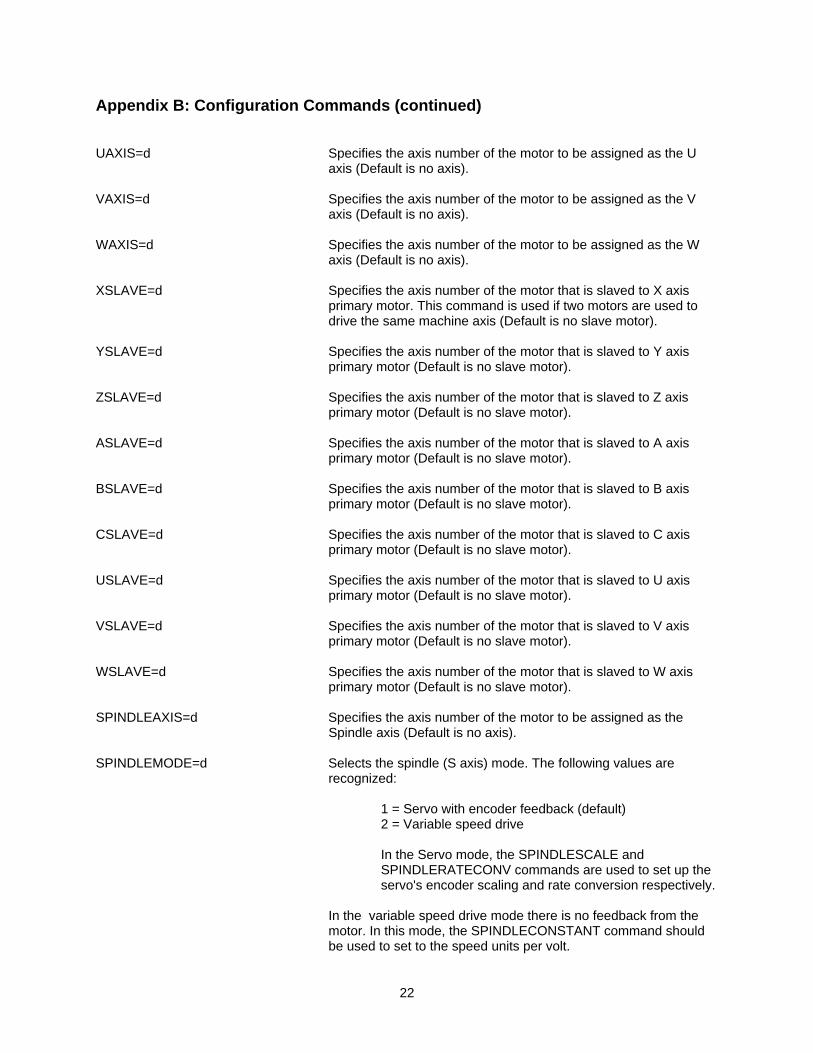
Appendix B: Configuration Commands (continued)
22
UAXIS=d Specifies the axis number of the motor to be assigned as the U
axis (Default is no axis). VAXIS=d Specifies the axis number of the motor to be assigned as the V
axis (Default is no axis). WAXIS=d Specifies the axis number of the motor to be assigned as the W
axis (Default is no axis). XSLAVE=d Specifies the axis number of the motor that is slaved to X axis
primary motor. This command is used if two motors are used to drive the same machine axis (Default is no slave motor).
YSLAVE=d Specifies the axis number of the motor that is slaved to Y axis
primary motor (Default is no slave motor). ZSLAVE=d Specifies the axis number of the motor that is slaved to Z axis
primary motor (Default is no slave motor). ASLAVE=d Specifies the axis number of the motor that is slaved to A axis
primary motor (Default is no slave motor). BSLAVE=d Specifies the axis number of the motor that is slaved to B axis
primary motor (Default is no slave motor). CSLAVE=d Specifies the axis number of the motor that is slaved to C axis
primary motor (Default is no slave motor). USLAVE=d Specifies the axis number of the motor that is slaved to U axis
primary motor (Default is no slave motor). VSLAVE=d Specifies the axis number of the motor that is slaved to V axis
primary motor (Default is no slave motor). WSLAVE=d Specifies the axis number of the motor that is slaved to W axis
primary motor (Default is no slave motor). SPINDLEAXIS=d Specifies the axis number of the motor to be assigned as the
Spindle axis (Default is no axis). SPINDLEMODE=d Selects the spindle (S axis) mode. The following values are
recognized:
1 = Servo with encoder feedback (default) 2 = Variable speed drive
In the Servo mode, the SPINDLESCALE and SPINDLERATECONV commands are used to set up the servo's encoder scaling and rate conversion respectively.
In the variable speed drive mode there is no feedback from the motor. In this mode, the SPINDLECONSTANT command should be used to set to the speed units per volt.
Appendix B: Configuration Commands (continued)
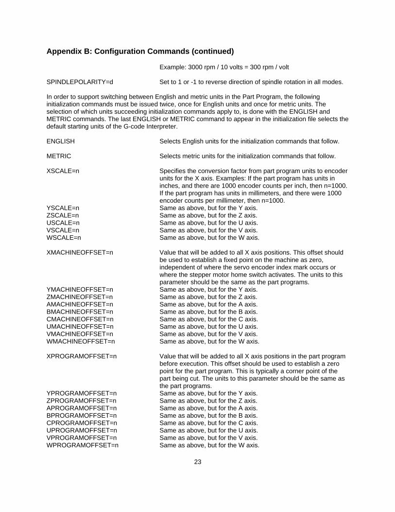
23
Example: 3000 rpm / 10 volts = 300 rpm / volt
SPINDLEPOLARITY=d Set to 1 or -1 to reverse direction of spindle rotation in all modes. In order to support switching between English and metric units in the Part Program, the following initialization commands must be issued twice, once for English units and once for metric units. The selection of which units succeeding initialization commands apply to, is done with the ENGLISH and METRIC commands. The last ENGLISH or METRIC command to appear in the initialization file selects the default starting units of the G-code Interpreter. ENGLISH Selects English units for the initialization commands that follow. METRIC Selects metric units for the initialization commands that follow. XSCALE=n Specifies the conversion factor from part program units to encoder
units for the X axis. Examples: If the part program has units in inches, and there are 1000 encoder counts per inch, then n=1000. If the part program has units in millimeters, and there were 1000 encoder counts per millimeter, then n=1000.
YSCALE=n Same as above, but for the Y axis. ZSCALE=n Same as above, but for the Z axis. USCALE=n Same as above, but for the U axis. VSCALE=n Same as above, but for the V axis. WSCALE=n Same as above, but for the W axis. XMACHINEOFFSET=n Value that will be added to all X axis positions. This offset should
be used to establish a fixed point on the machine as zero, independent of where the servo encoder index mark occurs or where the stepper motor home switch activates. The units to this parameter should be the same as the part programs.
YMACHINEOFFSET=n Same as above, but for the Y axis. ZMACHINEOFFSET=n Same as above, but for the Z axis. AMACHINEOFFSET=n Same as above, but for the A axis. BMACHINEOFFSET=n Same as above, but for the B axis. CMACHINEOFFSET=n Same as above, but for the C axis. UMACHINEOFFSET=n Same as above, but for the U axis. VMACHINEOFFSET=n Same as above, but for the V axis. WMACHINEOFFSET=n Same as above, but for the W axis. XPROGRAMOFFSET=n Value that will be added to all X axis positions in the part program
before execution. This offset should be used to establish a zero point for the part program. This is typically a corner point of the part being cut. The units to this parameter should be the same as the part programs.
YPROGRAMOFFSET=n Same as above, but for the Y axis. ZPROGRAMOFFSET=n Same as above, but for the Z axis. APROGRAMOFFSET=n Same as above, but for the A axis. BPROGRAMOFFSET=n Same as above, but for the B axis. CPROGRAMOFFSET=n Same as above, but for the C axis. UPROGRAMOFFSET=n Same as above, but for the U axis. VPROGRAMOFFSET=n Same as above, but for the V axis. WPROGRAMOFFSET=n Same as above, but for the W axis.
Appendix B: Configuration Commands (continued)
24
XRATECONV=n Used to set Rate Conversion factor. This value is determined by the time unit used when specifying the rate of motion for a particular axis. If rates are specified as inches per minute, the time unit is a minute. The Rate Conversion factor is defined to be the number of seconds per time unit. For example, if rates are specified in inches or millimeters per minute, the Rate Conversion factor is 60 seconds / 1 second = 60. If rates are specified in inches or millimeters per second, the Rate Conversion factor is 1second / 1second = 1.
YRATECONV=n Same as above, but for the Y axis. ZRATECONV=n Same as above, but for the Z axis. ARATECONV=n Same as above, but for the A axis. BRATECONV=n Same as above, but for the B axis. CRATECONV=n Same as above, but for the C axis. URATECONV=n Same as above, but for the U axis. VRATECONV=n Same as above, but for the V axis. WRATECONV=n Same as above, but for the W axis. XUPLIMIT=n X axis upper limit of travel. YUPLIMIT=n Y axis upper limit of travel. ZUPLIMIT=n Z axis upper limit of travel. AUPLIMIT=n A axis upper limit of travel. BUPLIMIT=n B axis upper limit of travel. CUPLIMIT=n C axis upper limit of travel. UUPLIMIT=n U axis upper limit of travel. VUPLIMIT=n V axis upper limit of travel. WUPLIMIT=n W axis upper limit of travel. XLOWLIMIT=n X axis lower limit of travel. YLOWLIMIT=n Y axis lower limit of travel. ZLOWLIMIT=n Z axis lower limit of travel. ALOWLIMIT=n A axis lower limit of travel. BLOWLIMIT=n B axis lower limit of travel. CLOWLIMIT=n C axis lower limit of travel. ULOWLIMIT=n U axis lower limit of travel. VLOWLIMIT=n V axis lower limit of travel. WLOWLIMIT=n W axis lower limit of travel. RAPIDRATE=n Rapid Rate for machine motion. This is the speed used for moving
the machine into position between cutting operations. RAPIDACCELERATION=n Rapid Rate Acceleration. RAPIDDECELERATION=n Rapid Rate Deceleration. FEEDRATE=n Feed Rate for machine motion. This is the speed used during
cutting operations. This value will typically be changed in the part program during execution. It is used as the default value if no feed rates are included in the part program.
FEEDACCELERATION=n Feed Rate Acceleration. Used for X, Y and Z axes. FEEDDECELERATION=n Feed Rate Deceleration. Used for X, Y and Z axes. SPINDLESCALE=n Spindle scale constant (counts / revolution) SPINDLERATECONV=n Spindle rate conversion (seconds / speed time unit)

Appendix B: Configuration Commands (continued)
25
SPINDLECONSTANT=n Spindle output constant (speed units / volt) SPINDLESPEED=n Speed of spindle. This is the speed used when the spindle is
turned on with the M04 or M05 codes. This value will typically be changed in the part program during execution. It is used as the default value if no speed changes are included in the part program.
SPINDLEACCELERATION=n Spindle Acceleration. SPINDLEDECELERATION=n Spindle Deceleration. AACCELERATION=n Acceleration and deceleration rates for each of the ADECELERATION=n independent axes. BACCELERATION=n BDECELERATION=n CACCELERATION=n CDECELERATION=n UACCELERATION=n UDECELERATION=n VACCELERATION=n VDECELERATION=n WACCELERATION=n WDECELERATION=n INCREMENT=n This parameter is used to specify the maximum angle change that
can occur in a continuous motion. This value can also be changed within a G-code part program by an 'E' word.

26
Appendix C: Work Coordinate Initialization File ; This is an example of a Work Coordinate Initialization File ; The G-code Interpreter supports 6 work coordinate systems ; Only the first 2 are initialized in this file WORKCOOR=1 ENGLISH X=0 Y=0 Z=0 A=0 B=0 C=0 U=0 V=0 W=0 METRIC X=0 Y=0 Z=0 A=0 B=0 C=0 U=0 V=0 W=0 WORKCOOR=2 ENGLISH X=1.0 Y=2.0 Z=-3.0 A=0 B=0 C=0 U=0 V=0 W=0 METRIC X=25.4 Y=50.8 Z=-76.2 A=0 B=0 C=0 U=0 V=0 W=0

27
Appendix D: Tool Data Initialization File ;This is an example of a Tool Data initialization file ; For "Tool Offset by Tool Number" the G-code Interpreter holds data for 9 tools ; Only the data for the first 2 are initialized in this file TOOL=1 Q=0 ;Tool orientation F=0.001 ;Tool radius wear factor (change in wear per unit of cutting travel) ENGLISH X=0 ;X offset Y=0 ;Y offset Z=2.0 ;Z offset R=0.25 ;Tool radius W=0.01 ;Tool radius wear compensation (actual = tool radius - wear) METRIC X=0 Y=0 Z=50.8 R=6.35 W=0.25 TOOL=2 Q=0 F=0.001 ENGLISH X=0 Y=0 Z=0.39370078 R=0.078740156 W=0.0039 METRIC X=0 Y=0 Z=10 R=2 W=0.1
28
;For "tool offset by D and H codes" the G-code Interpreter holds data for 32 offsets ; Only the data for the first 2 are initialized in this file DGEOMETRYOFFSETS 1=0.5 2=0.25 DWEAROFFSETS 1=0.0 2=0.0025 DWEARFACTORS 1=0.0 2=0.0001 HGEOMETRYOFFSETS 1=3.0 2=1.25 HWEAROFFSETS 1=0.025 2=0.0 HWEARFACTORS 1=0.0002 2=0.0

Precision MicroControl Corporation 2075-N Corte del Nogal
Carlsbad, CA 92011 * USA
Tel: +1-760-930-0101 Fax: +1-760-930-0222
www.pmccorp.com
Information: [email protected] Technical Support: [email protected]