Embed Size (px)
Citation preview

Information Fusion 6 (2005) 129–141
www.elsevier.com/locate/inffus
Fusion of infrared vision and radar for estimatingthe lateral dynamics of obstacles
Angelos Amditis a,*, Aris Polychronopoulos a, Nikolaos Floudas a, Luisa Andreone b
a National Technical University of Athens, 9 Iroon Polytechniou str., 15773 Athens, Greeceb Centro Ricerche FIAT (CRF), Italy
Received 1 February 2004; received in revised form 4 June 2004; accepted 4 June 2004
Available online 6 July 2004
Abstract
Automotive forward collision warning systems are based on range finders to detect the obstacles ahead and warn or intervene
when a dangerous situation occur. However, the radar information by itself is not adequate to predict the future path of vehicles in
collision avoidance systems due to the poor estimation of their lateral attribute. In order to face this problem, this paper proposes
the utilization of a new Kalman based filter, whose measurement space includes data from a radar and a vision system. Given the
superiority of vision systems in estimating azimuth and lateral velocity, the filter proves to be robust in vehicle maneuvers and
curves. Results from simulated and real data are presented, providing comparative results with stand alone tracking systems and the
cross-covariance technique in multisensor architectures.
� 2004 Elsevier B.V. All rights reserved.
Keywords: Fusion; Infrared; Radar; Kalman filter; Path prediction; Collision avoidance
1. Introduction
The ultimate scope of an automotive preventive
safety system is the reduction of road accidents, espe-cially those caused by human errors, which represent the
90% of fatal road accidents [1]. Adaptive Cruise Control
(ACC) system is a radar based system, which maintains
the distance from the preceding vehicle and prevents
rear-end collisions with the obstacles in front. The lim-
itations of such systems have been identified (e.g. in
[2,3]) and the development of next generation ACC and
forward collision warning (FCW) systems is in progress,while research has shown that systems using only one
sensor often lack reliability and robustness in specific
situations [4]. However, although promising results have
been achieved in sensor technologies, not much research
effort has been spent to the design and implementation
*Corresponding author. Tel.: +30-210-7722398/6973993853; fax:
+30-210-7722291.
E-mail addresses: [email protected] (A. Amditis), arisp@
mail.ntua.gr (A. Polychronopoulos), [email protected] (N. Flou-
das), [email protected] (L. Andreone).
1566-2535/$ - see front matter � 2004 Elsevier B.V. All rights reserved.
doi:10.1016/j.inffus.2004.06.002
of multisensor multiobject tracking algorithms in auto-
motive applications.
The problem addressed in this paper is the inaccurate
estimation of the lateral motion of obstacles in front byrange finders. Although radars are robust against bad
weather (e.g. rain and fog), they do not have enough
angular resolution. This fact is a source of false alarms
and misses in automotive real-time applications. In
contrast, vision sensors carry out efficient lateral esti-
mation, but fall short in estimating longitudinal
parameters, which are perfectly evaluated by mmw ra-
dars [5,6]. Stereo vision allows reliable depth measure-ments up to a disparity of 5 pixels, which corresponds
only to a maximum operative distance of 50–60 m [4],
while the radar range reaches 150–200 m of range.
In Figs. 1 and 2, the position measurement errors of
the two sensors utilized in the paper are shown. In Fig.
1, the resolution of the radar is depicted and corre-
sponds to radial and angular accuracy of rR ¼ 1 m and
rh ¼ 0:01 rad respectively. The field of view of the radaris about ±11�. The resolution of the vision sensor, which
has a field of view of about ±10�, is depicted in Fig. 2.
The vision sensor, using image processing techniques,

Fig. 2. Camera accuracy after transition to ground plane (field of view
about ±10�).
Fig. 1. Radar accuracy on ground plane (field of view about ±11�).
130 A. Amditis et al. / Information Fusion 6 (2005) 129–141
delivers the position of the obstacles in the image plane.
The transition from image to ground plane, which is
needed for the spatial alignment of the sensors, and thepitch angle of the vehicle insert uncertainty in longitu-
dinal axis. The lateral position is unaffected from pitch
and, thus, the error is less and the measurements are
more credible. On the other hand, the lateral estimation
of the radar is affected from the poor quality of angle
measurements. As shown in Fig. 1, in large distances,
the efficiency is falling, while the camera’s estimation
can be valuable.Thus, a fusion system consisted of a mmw radar and
a vision system can improve the motion parameters’
estimation of objects tracked by an automotive system.
Data fusion is naturally recognized as the only promis-
ing technique to generate a new ‘‘artificial’’ sensor,
which, while combines to the maximum possible extent
the individual sensor capabilities, strives simultaneously
to eliminate their drawbacks. In literature, this combi-
nation is often met [5,7–9] using the information of the
radar sensor for segmentation or the definition of searchareas in the image to realize video-based (stereo or
mono) obstacle detection and lane tracking systems. In
[4], the fusion algorithm consists of two steps, namely,
obstacle detection and lane tracking. The longitudinal
and lateral estimation are separated; the former is radar
based with a constant velocity model, while the latter is
based on the assumption that the derivative of the lane
position is zero.Research on sensor fusion is focusing on improving
vision systems’ performance. In [10], an innovative
multihypothesis tracking scheme is proposed for radar
tracking and it seems promising for its detection rate,
but it does not take care of the properties of the lateral
motion. In contrast, this paper proposes a new tracking
filter in ground plane that estimates accurately the lat-
eral velocity of automobiles using a mmw radar and afar infrared camera (FIR). The target application is the
support of next generation collision warning and
avoidance systems in night and adverse weather condi-
tions.
In the proposed algorithm, as in [4], the longitudinal
and lateral motion of the vehicle is separated. The
method introduced in the paper has a hybrid tracking
architecture which deploys both measurements andtracks in an Uncoupled Double Filter (UDF) that
compensates the dynamics of moving obstacles tracked
by an automotive fusion platform, integrated on a test
vehicle. The Uncoupled Double Filter consists of a
mixture of range and angle filters in polar coordinates,
where radar tracks are considered as range filter mea-
surements and camera tracks as angle filter measure-
ments respectively. The coexistence of the abovementioned sensors is a prerequisite for the proper
functionality of the method.
The structure of the paper is as follows. It starts
giving the structure of the radar and image tracking
system that allows the implementation of the proposed
method. In the tracking architecture of the radar, all
individual parts (data association, filters, track man-
agement etc.) are designed given the limitations of real-time automotive systems; in the image tracking, image
processing and correlation data association are de-
scribed given a real-time frame grabbing process. In
turn, the fusion methods for the overall system are de-
scribed. Initially, the cross-covariance method for the
two sensors is presented and then the UDF algorithm is
introduced. The results are tested by means of simulated
data sets and real data, as well. For the tests, a collisionwarning and night vision system is the use case incor-
porating data from a mmw radar and images from a far
infrared camera. The paper ends with a brief remark on
A. Amditis et al. / Information Fusion 6 (2005) 129–141 131
the potential of the method in predicting the path of the
obstacles in collision warning and collision avoidance
systems.
2. Tracking system design
As mentioned in Section 1, the proposed system
incorporates both tracks and measurements from the
radar and the far infrared camera. The proposed UDF is
not efficient in a system where the probability of false
measurement to track assignment is high. Thus, two
autonomous distributed trackers for the camera and theradar coexist and generate tracks. Although the tracking
architectures differ, they both produce tracks in Carte-
sian coordinates. In the remainder of the section these
tracking schemes are presented briefly, giving emphasis
to the motion modeling of the observed obstacles. The
results of these autonomous systems will be used in the
proposed fusion approach and at the same time they will
be treated as stand-alone systems for comparisons inSection 4.
2.1. Radar tracking system
In this paragraph, the main parts of a radar tracking
system will be mentioned briefly. In general, the radar
tracking scheme adopted was proposed by [11], tailored
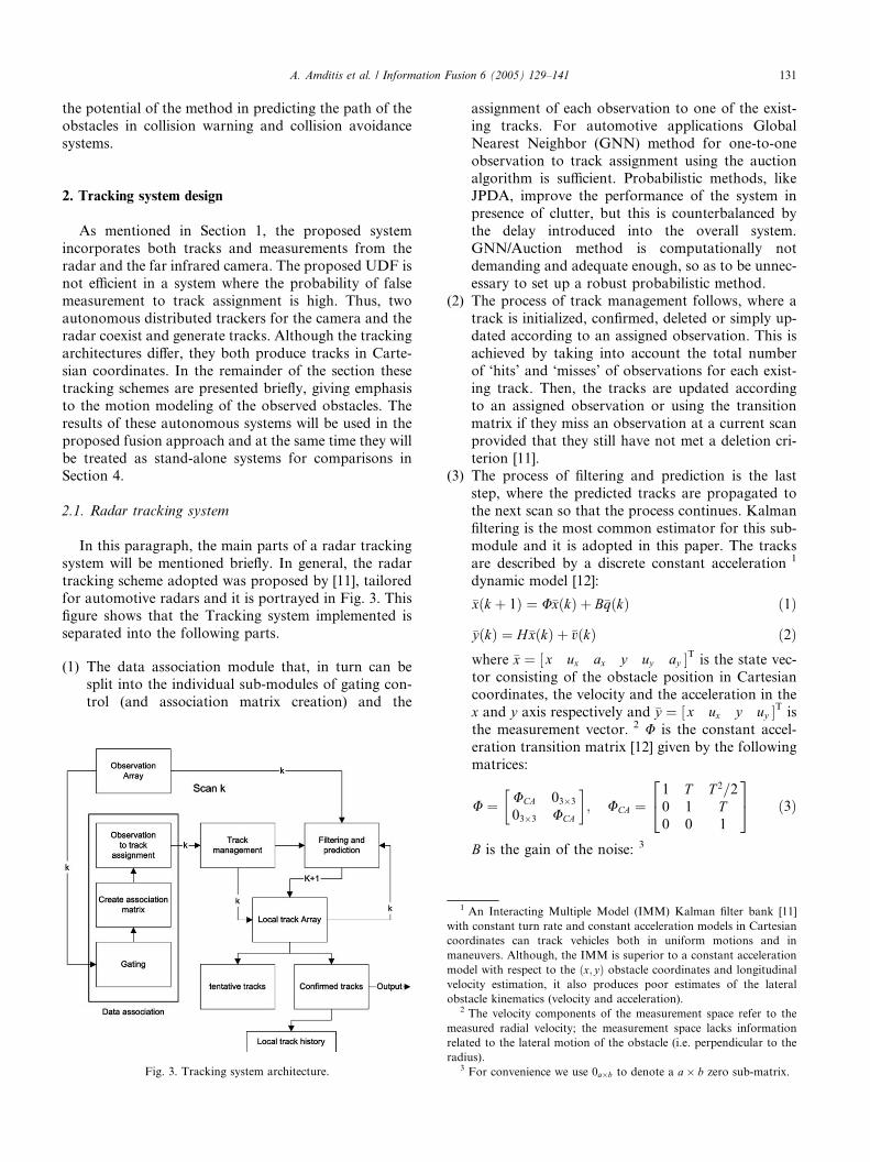
for automotive radars and it is portrayed in Fig. 3. Thisfigure shows that the Tracking system implemented is
separated into the following parts.
(1) The data association module that, in turn can besplit into the individual sub-modules of gating con-
trol (and association matrix creation) and the
Fig. 3. Tracking system architecture.
assignment of each observation to one of the exist-
ing tracks. For automotive applications Global
Nearest Neighbor (GNN) method for one-to-one
observation to track assignment using the auction
algorithm is sufficient. Probabilistic methods, likeJPDA, improve the performance of the system in
presence of clutter, but this is counterbalanced by
the delay introduced into the overall system.
GNN/Auction method is computationally not
demanding and adequate enough, so as to be unnec-
essary to set up a robust probabilistic method.
(2) The process of track management follows, where a
track is initialized, confirmed, deleted or simply up-dated according to an assigned observation. This is
achieved by taking into account the total number
of ‘hits’ and ‘misses’ of observations for each exist-
ing track. Then, the tracks are updated according
to an assigned observation or using the transition
matrix if they miss an observation at a current scan
provided that they still have not met a deletion cri-
terion [11].(3) The process of filtering and prediction is the last
step, where the predicted tracks are propagated to
the next scan so that the process continues. Kalman
filtering is the most common estimator for this sub-
module and it is adopted in this paper. The tracks
are described by a discrete constant acceleration 1
dynamic model [12]:
�xðk þ 1Þ ¼ U�xðkÞ þ B�qðkÞ ð1Þ
�yðkÞ ¼ H�xðkÞ þ �vðkÞ ð2Þwhere �x ¼ ½ x ux ax y uy ay �T is the state vec-
tor consisting of the obstacle position in Cartesiancoordinates, the velocity and the acceleration in the
x and y axis respectively and �y ¼ ½ x ux y uy �T is
the measurement vector. 2 U is the constant accel-
eration transition matrix [12] given by the following
matrices:
U ¼ UCA 03�3
03�3 UCA
� �; UCA ¼
1 T T 2=20 1 T0 0 1
24
35 ð3Þ
B is the gain of the noise: 3
1 An Interacting Multiple Model (IMM) Kalman filter bank [11]
with constant turn rate and constant acceleration models in Cartesian
coordinates can track vehicles both in uniform motions and in
maneuvers. Although, the IMM is superior to a constant acceleration
model with respect to the ðx; yÞ obstacle coordinates and longitudinal
velocity estimation, it also produces poor estimates of the lateral
obstacle kinematics (velocity and acceleration).2 The velocity components of the measurement space refer to the
measured radial velocity; the measurement space lacks information
related to the lateral motion of the obstacle (i.e. perpendicular to the
radius).3 For convenience we use 0a�b to denote a a� b zero sub-matrix.

Fig. 4. Infrared image.
132 A. Amditis et al. / Information Fusion 6 (2005) 129–141
B ¼ BCA 03�1
03�1 BCA
� �; BCA ¼ T 2=2 T 1
� �T ð4Þ
and �qðkÞ is the zero-mean, white, Gaussian process
noise with known covariance Q:
Q ¼ B � r2ax 0
0 r2ay
� �� BT ð5Þ
where rax; ray are the standard deviations of the
acceleration noise in the two axes. H is the mea-
surement matrix:
H ¼ H1 02�3
02�3 H1
� �; H1 ¼
1 0 0
0 1 0
� �ð6Þ
Finally, �vðkÞ is the zero-mean, white, Gaussian
measurement noise with known covariance R: 4
R ¼ diagðr2x ; r
2ux; r
2y ; r
2uyÞ ð7Þ
where rx, ry , rux, ruy are the standard deviations of
the radarmeasurement errors for the position and the
velocity of the obstacle in the two axes respectively.
2.2. Image tracking system
In this paragraph, the main parts of a camera
tracking system will be mentioned briefly. The camera
tracking system involves the transition of processed
objects from image to ground plane, which introduces
non-linearities to the system, as it will shown in the
remainder. The objects detected in the image are deliv-
ered in pixel coordinates. A calibration matrix 5 trans-
forms the coordinates of the obstacles from pixels toCartesian coordinates. This transformation is a major
source of errors as the pitch of camera is ‘‘transformed’’
as backdrop (longitudinal position) uncertainty.
IR sensors convey information about the temperature
of objects and not typical features of the visible domain
[13]. The temperature of the vehicle is mainly concen-
trated on the wheels, the engine and the muffler and it
strongly depends on travel time. The image processingand tracking algorithm deal with the identification of
objects of interest in the image plane. The algorithm
focuses on the hot blobs in the IR image (Fig. 4), fol-
lowed by the selection of bounding boxes which are
considered as possible candidates. Vehicles are, then,
identified among the candidate objects based on specific
features related to their shape. A tracking phase follows,
allowing confirming the hypotheses through the analysisof the temporal behavior of the object. Correlation
tracking is selected, since it is less affected by back-
4 For convenience we use the shorthand notation A ¼ diagð�Þ to
denote a block diagonal square matrix A. The values in brackets are
the non-zero diagonal elements; all the other elements are zero.5 The elements of the calibration matrix depend on the camera’s
characteristics i.e. focal length, skewness factor and camera height.
ground in the tracking gate, in comparison with the
other image tracking approaches [12] like edge or cen-
troid tracking. The fact that hot blobs are in general
below the car (wheel, exhaust) is also taken into ac-
count, with the accumulation of an offset.
The infrared camera, after image processing and
correlation tracking, extracts the coordinates of image
row i and image column j of a pixel representing thecentroid of the bounding box, the object height (row) Diand the object width (column) Dj. The centroid of the
boxes ½ i j �T is selected as measurement input for the
camera tracker. The measurement vector is �y ¼ ½ i j �Tand state vector is selected as �x ¼ ½ x ux y uy �T and
contains the position and the velocity of the obstacles in
x and y Cartesian coordinates respectively. In terms of
the motion modeling, the transition from time instant kto k þ 1 is carried out through a linear constant velocity
transformation.
The mapping from measurement space to the state
space is not linear and can be described as follows, given
the time instant k:
ij
� �¼
a11xþ a12y þ a13a31xþ a32y þ a33
a21xþ a22y þ a23a31xþ a32y þ a33
2664
3775 ð8Þ
The parameters alk (l ¼ 1, 2, 3 and k ¼ 1, 2, 3) are the
camera calibration parameters for 2D image plane to
2D ground plane transformation. The calibration pro-
cedure is carried out by acquiring images of hot objectsat known distances together with the knowledge of
intrinsic calibration parameters. These elements have
such values that x is mainly depended on i, and y on j. Ingeneral, the lateral position (y-coordinate) has high
reliability, while the longitudinal parameters of the
obstacles suffer from uncertainty, as explained in the
introduction.
In view of the fact that the mappings of the statespace to the sensor measurement spaces are non-linear,
linearization using the Jacobi matrices is used in an
Extended Kalman filter system. This equation is line-
arized using a measurement matrix as follows:
Hðx; yÞ ¼ h11 0 h13 0
h21 0 h23 0
� �ð9Þ

A. Amditis et al. / Information Fusion 6 (2005) 129–141 133
h11 ¼a11ða31xþ a32y þ a33Þ a31ða11xþ a12y þ a13Þ
ða31xþ a32y þ a33Þ2
ð9aÞ
h13 ¼a12ða31xþ a32y þ a33Þ a32ða11xþ a12y þ a13Þ
ða31xþ a32y þ a33Þ2
ð9bÞ
h21 ¼a21ða31xþ a32y þ a33Þ a31ða21xþ a22y þ a23Þ
ða31xþ a32y þ a33Þ2
ð9cÞ
h23 ¼a22ða31xþ a32y þ a33Þ a32ða21xþ a22y þ a23Þ
ða31xþ a32y þ a33Þ2
ð9dÞThe non-linearity appears in the measurements transi-
tion and not in the motion model. Thus, following the
terminology of Section 2.1, the transition matrix and the
covariance matrices are:
U ¼ UCV 02�2
02�2 UCV
� �; UCV ¼ 1 T
0 1
� �ð10Þ
B ¼ BCV 02�1
02�1 BCV
� �; BCV ¼ T
1
� �ð11Þ
Q ¼ B � r2ux 0
0 r2uy
� �� BT ð12Þ
R ¼ r2i 00 r2
j
� �ð13Þ
where rux, ruy is the velocity processes noise standard
deviations in m/s and ri, rj are the measurement error
standard deviations in the two image plane axes inpixels. A tracking system, similar to this described in
Fig. 3, can be implemented and provide tracked quan-
tities for position and velocity of the moving obstacles.
Given the above analysis, radar and camera trackers
can serve as stand-alone systems in a collision warning
system and they will be treated as such only for com-
parative results. Moreover, since the distributed system
produces radar and camera state vectors and track IDsrespectively, the fusion processor is able to carry out
track to track association and fusion.
3. Fusion of infrared vision and Radar for lateral control
Initially a fusion system demands an alignment step of
the sensors involved both in time and in space domain. Inthe time domain, synchronous and asynchronous ap-
proaches have been proposed (e.g. [14]); however, with-
out loss of generality, in this paper as far as the simulated
data sets are concerned, it will be assumed that sensors
are synchronized and they both deliver tracks in a con-
stant refresh rate T . The most crucial issue appears to be
the space alignment which refers to the association pro-
cess of the radar and the camera tracks. A pure geometric
method would not be suitable, as range measurements ofFIR fail due to pitch effect and consequently the perti-
nent estimation parameters are poor. Thus, a ‘‘lateral’’
track to track association seems to be a sufficient solu-
tion: every radar track (and camera track) is assigned to
a lane given the estimation of the y coordinate and the
road geometry. The estimation of the road geometry is a
model based Kalman estimator which uses the radar
echoes of the stationary detected objects (e.g. guardrailsor high grass)––the model that describes the road
geometry in terms of curvature and curvature rate is the
clothoid model [15]. The camera and radar tracks that
belong to the same lane are associated and formulate the
measurement space for the fusion processor. It should be
mentioned, though, that radar tracks usually are more
than camera tracks, thus, the fusion algorithm is not
implemented for the whole number of radar tracks. Themost famous fusion algorithm in distributed fusion sys-
tems is the cross-covariance technique [16]. A cross-
covariance matrix PRC can be computed to define the
error correlation between two sensor level tracks on the
same obstacle. Then, a combined state estimate x_f that
minimizes the expected error can be created from the two
sensor level track state estimates and their covariances
ðx_R; PRÞ, ðx_C; PCÞ, representing the radar and camera
tracks respectively, ðx_R; PRÞ, ðx_C; PCÞ are fused using the
cross-covariance, PRC, method. Every element ðl;mÞ of
the cross-covariance matrix is given by the following
formula:
PRCðl;mÞ ¼ qffiffiffiffiffiffiffiffiffiffiffiffiffiffiffiffiffiffiffiffiffiffiffiffiffiffiffiffiffiffiffiffiffiffiffiffiPRðl;mÞ � PCðl;mÞ
pð14Þ
where q is a correlation coefficient calculated a priori.
The fused state vector and the corresponding covariance
matrix are given by the following equations respectively:
x_
f ¼ x_
R þ C½x_C x_
R� ð15Þand
Pf ¼ PR ½PR PRC�U1RC½PR PRC�T ð16Þ
where C ¼ ½PR PRC�U1RC and URC ¼ PR þ PC PRC
PTRC.Since Bar-Shalom in [16] firstly introduced the
method, there were proposed modified versions. For
example, Gao and Harris, in [17], propose a modified
track to track fusion algorithms which prove to have
better performance when using dissimilar sensors.
However, the method in [16] is the one that will be used
in the paper for comparative results.
Although the cross-covariance method (and itsmodifications) is superior to the individual trackers, it
will be shown that fails in estimating the lateral velocity
of obstacles, as longitudinal estimation from IR sensors

Fig. 5. Uncoupled double filter (UDF) flowchart.
134 A. Amditis et al. / Information Fusion 6 (2005) 129–141
inserts much noise and outbalance the system’s effi-
ciency. The UDF filter that is introduced in theremainder is designed to overcome this problem and to
ensure robust lateral control of moving obstacles. The
proposed UDF, in turn, is a double filter––range and
angle filter in parallel––that gets measurements from
both sensors in a polar coordinate system. The theo-
retical background and systematic comparison for
uncoupled range and angle filters is given in [12]. The
measurements are pertinent to the fused tracks––obsta-cles, which were formulated in the track to track asso-
ciation process. 6 This approach facilitates decoupling
so that separate angle and range filters can be used. The
flowchart of the UDF is depicted in Fig. 5. The range
filter is based on radar measurements (range and range
rate) and consists of three states, namely the range, the
range rate and the radial acceleration: xr ¼½R uR aR �T. In turn, the angle filter is based on the ycamera measurement (transformed in ground plane
through the calibration matrix) and the x radar mea-
surement (transformed from the polar measurement
space). An ‘‘artificial’’ raw measurement for the angle is
then calculated, which appears to be the best solution
for the measurement space of the angle filter: 7
h ¼ tan1 ycamera
xradar
�ð17Þ
The angle filter consists of the azimuth angle, the lateral
velocity and the lateral acceleration: xa ¼ ½ h uL aL �T.The lateral acceleration is necessary, since even a con-
stant velocity obstacle does not produce a constant lat-
eral velocity motion [12]. Thus, high order derivatives
6 Practically, the formulated fused tracks refer to the most close and
dangerous obstacles ahead in collision warning systems.7 Taking the angle measurement exclusively from the camera
tracker causes fails because of the already mentioned problem of poor
longitudinal observations by the IR camera.
are required in the UDF filter for the lateral control of
moving vehicles.As it will be shown and is depicted in Fig. 5, the range
filter needs estimated parameters from the angle filter
and vice versa.
Let~a ¼ aR r_ þ aL h
_
and~u ¼ uR r_ þ uL h
_
be the vectors
of the acceleration and the velocity of an obstacle in a
polar coordinate system ð r_; h_
Þ. The centre of the coor-
dinate system ð0; 0Þ is always the frontal bumper of the
subject vehicle 8 and all parameters of the motion of theobstacles are relative to subject vehicle’s motion. With
these assumptions, the dynamic equations of the UDF
will be derived straightforwardly. A proof of the transi-
tion equations is given in Appendix A of the paper. Eqs.
(1) and (2) describe the control system for each filter of
UDF. In the range filter, it is assumed that the derivative
of the acceleration can be modeled as zero mean
Gaussian noise with standard deviation qaR . The transi-tion matrix depends on the angular velocity x of the
obstacle, whose estimated value is provided by the angle
filter. In a similar way, for the angle filter, it is assumed
that the derivative of the lateral acceleration can be
modeled as zero mean Gaussian noise with standard
deviation qaL . The transition matrix depends on the
estimation of the velocity and range from the range filter.
The transition, in discrete time, between scan k andscan k þ 1 is given by the following equation for both
filters below:
Rðk þ 1ÞuRðk þ 1ÞaRðk þ 1Þ
264
375 ¼
1þ x2ðkÞT 2
2T T 2
2
x2ðkÞT 1 T
0 0 1
264
375 �
RðkÞuRðkÞaRðkÞ
264
375
þT 2
2
T
1
264
375 � qaRðkÞ ð18Þ
8 Subject vehicle is defined as the vehicle that carries the sensorial
system––the sensor vehicle.

A. Amditis et al. / Information Fusion 6 (2005) 129–141 135
hðk þ 1ÞuLðk þ 1ÞaLðk þ 1Þ
24
35 ¼
1 TRðkÞ 1 uRðkÞT
RðkÞ
� �T 2
2RðkÞ0 1 T0 0 1
264
375
�hðkÞuLðkÞaLðkÞ
24
35þ
T 2
2RðkÞT1
24
35 � qaLðkÞ ð19Þ
Moreover, Br ¼ ½ T 2=2 T 1 �T and the covariance
matrices are
Qr ¼ Brðr2aRÞBT
r ; Rr ¼r2R 0
0 r2uR
� �
for the range filter and Ba ¼ ½ T 2=2RðkÞ T 1 �T and
Qa ¼ Baðr2aLÞBT
a , Ra ¼ ðr2hÞ for the angle filter. From the
above, it is regarded that the filters are of constant radial
acceleration (the standard deviation of process noise is
raR) and constant lateral acceleration (the standard
deviation of process noise is raL), respectively. The
standard deviations for the range, range rate and anglemeasurements are rR; ruR ; rh respectively.
The advantage of UDF, shown in Eq. (19), is that the
lateral attribute of a moving obstacle is estimated
accurately in a simple and linear manner. It keeps the
property of the cross-covariance method by reducing the
computational load in the central processor skipping
EKF solutions and iterative processes. The mapping of
the measurement space to the state space for both filtersis also linear as quantities from the state vector are di-
rectly observed by the artificial measurement space of
UDF. Below, in Section 4, results will show UDF’s
superiority against other fusion techniques and single
sensor systems.
9 Radial parameters between single radar processing and UDF do
not differ significantly and they are omitted from the verification trials.
4. Simulations and comparative results
This section verifies the performance of UDF system
in predicting the lateral characteristics of moving
obstacles on the road, which makes it suitable for future
collision warning applications. Verification based on
real scenarios on the road and relevant sensor data
suffers from lack of ground truth data. Although they
represent a real system, it is not possible to producecomparative results. On the other hand, a driving sim-
ulator produces ground truth data as the user wishes,
thus, it is selected as the most reliable means of algo-
rithm evaluation. The verification of the algorithms,
using real data, will also be carried out by evaluating
their impact on a collision warning system and more
particular to the path prediction of a moving obstacle,
where comparative results will be given. All figures inthis section aim to compare the behavior of UDF system
versus the conventional track to track fusion and single
camera and radar individual trackers.
4.1. Results from a driving simulator
The simulator approximates vehicle’s motion by
making some assumptions for the data so as to be as
realistic as possible. The ‘‘true’’ position extracted by thesimulator is subject to Gaussian noise with given stan-
dard deviation, in order to approximate the character-
istics of the real sensors. The acceleration and the
steering angle change according to the user’s choice
being an input to the simulator. The simulator’s strength
is the fact that the user can control the values of these
two parameters so as the obstacle to move on realistic
situations of different traffic and road environments. Asthe radial parameters are perfectly estimated by radar
sensor 9 (and consequently by the range filter of the
UDF), the lateral parameters (angle, lateral velocity and
lateral acceleration), are chosen for UDF verification.
The developed scenario is related to a vehicle moving in
front of the subject vehicle, while the simulation runs
200 successive Monte Carlo iterations. At scan 60––i.e.
t ¼ 6 s––the moving object makes a lane changemaneuver, moving from the right lane towards the left
lane of a highway. The subject vehicle is moving with
constant velocity and zero angular velocity.
In Fig. 6(a), the azimuth angle is estimated by
the UDF, the radar tracker, the camera tracker and the
conventional track to track fusion. The true value of the
azimuth is also plotted. The comparisons are preformed
by means of their Root Mean Square (RMS) value foreach method, where the UDF proves its superiority.
As it is also shown in Fig. 6(b), where the lateral
velocity estimation is depicted for all methods, UDF is
the only method which can observe and estimate it.
UDF produces small errors and deviations from the true
value only when the maneuver starts––less than 0.2 m/
s––whereas the camera tracker and the track to track
fusion produce large estimation errors. The radartracker fails completely due to the fact that it is insuf-
ficient to estimate lateral velocity from Doppler radial
measurement of range rate.
Consequently, from Fig. 6(b), it is obvious that UDF
surpass the effectiveness of all the other methods, which
are the single sensor trackers and the cross-covariance
fusion of the two track arrays. The above figures show
that, although the overall estimation of simulated vehi-cle motion by the UDF is successful, the other methods
fail in tracking the maneuver. Thus, UDF appears to
perform sufficiently, but more trials with real world data
are needed, since no simulator can describe a true
highway driving instance exactly. This occurs because of
(a) unexpected driving situations and variations of dri-
ver behavior, (b) clutter in the environment and sensor

Fig. 6. (a) Angle estimation for a maneuvering obstacle using the four
different methods (simulation data). (b) Lateral velocity estimation for
a maneuvering obstacle using the four different methods (simulation
data).
136 A. Amditis et al. / Information Fusion 6 (2005) 129–141
failures, (c) excessive pitch for the camera and (d)
presence of many reflectors that create ‘‘ghost’’ obstacles
in the radar detections. This, of course, does not de-
crease the importance and the usefulness of the driving
simulator as a testing tool able to give a reliable evalu-
ation of the experimental system before it is tested under
real conditions. The evaluation of UDF under real
conditions follows.
4.2. Results with real data
The same methods have been applied to real world
data sets that have been recorded in Italian roads in the
periphery of Turin. The recordings were carried out for
the purposes of the European research program EU-
CLIDE [18]. The data represents various traffic scenar-ios in highways, rural roads and in presence of noisy
environments. Real data are used to ensure that the
system works appropriately in real conditions, though it
is difficult to check its efficiency, because of the absence
of the ground truth data as mentioned before. The
covariance matrix of the estimation error that derives
from Kalman equations is also a measure of the qualityof estimation. The individual standard deviations––i.e.
the diagonal elements of the covariance matrix––and the
correlation coefficients calculated from the covariance
matrix converge to their lower bounds. The data set that
has been selected for demonstration in this paper com-
prises of a vehicle ahead of the subject vehicle, which
makes relative maneuvers with respect to the subject
vehicle’s motion.In Fig. 7(a), the estimation of the angle is plotted for
the different methods. As it was commented in the
simulation results, all methods seem to observe the
maneuver, with different performances. The radar
tracker estimates the angle with fluctuations due to its
resolution and the fact that the obstacles do not have
fixed reflection points e.g. at scan 70 the radar falsely
observes a change in the angle h. The UDF seems toperform a smoothing due to the artificial measurement
for the angle as described in Eq. (17).
In Fig. 7(b), the lateral velocity estimation is plotted
for the same data set and for all four methods. The
radar, as in the simulator data, fails and produces large
estimation errors, even larger than in the simulator. The
camera tracker behaves in a similar manner as in the
simulation and also fails, producing smaller errors thanthe radar as expected. The conventional track to track
fusion is influenced by the wrong biases of the radar (for
example at scan 30––before the maneuver starts), but
produces smaller errors than the single sensor trackers.
The UDF produces logical estimates, smoothing the
available data, as it was verified also by analyzing the
behavior of the driver through the video sequences. Fi-
nally, the radar, as shown in Fig. 7(c), fails completelywhen estimating the lateral acceleration of the obstacle,
while UDF gives an estimation of 0.5 m/s2 when
maneuvering and almost zero otherwise.
In the remainder, it will be demonstrated the poten-
tial of UDF in predicting vehicles’ paths in collision
warning applications. This demonstration also serves
the performance evaluation of the results of Section 4.2.
4.3. A path prediction application for collision
warning systems
A path prediction application is a critical module of a
collision warning system. It intends to forecast, to the
best possible extend, the future position of the subject
vehicle and in general of all moving obstacles (e.g.
[3,19]). This can be achieved by several means andmethods, but it is usually based on the estimated
dynamics by Kalman recursive filters. The subject
vehicle’s path is estimated using the velocity, the accel-

Fig. 7. (a) Angle estimation for a maneuvering obstacle using the four different methods (real data). (b) Lateral velocity estimation for a maneuvering
obstacle using the four different methods (real data). (c) Lateral acceleration estimation for a maneuvering obstacle using the two different methods
(real data). The camera tracker does not output acceleration parameters.
A. Amditis et al. / Information Fusion 6 (2005) 129–141 137
eration, the angular velocity and/or the other motion
parameters available from inertial sensors (e.g. odome-
ter, steering wheel angle and yaw rate sensor). On theother hand, the moving obstacles’ paths are predicted
from the states estimated by radar or other sensors
integrated on the subject vehicle. The concept of the
predicted path is based on the propagation of the state
vector and the second order statistics to the future (i.e. a
number of future successive scans that represent a pre-
defined time frame), using the transition matrix and a
motion model as described in Section 2. While, thesubject vehicle’s path can be estimated even with an a-btracker, the prediction of the path of the obstacles
usually fails due to radar constraints and inefficient
algorithms. For that reason, in such systems, where
safety is the primary goal, the warning strategies are
designed in a deterministic way, depending mostly on
the obstacle’s position and not on its estimated future
trajectory.It will be shown how uncertainties in the lateral
estimation (i.e. lateral velocity and acceleration) can
assign false trajectories to the moving obstacles, which
in turn leads to false alarms in collision warning systems
and how UDF surpass this problem and gives an
accurate path. The scenario selected for the verification
is the same with Section 4.2, consisting of 110 scans and
providing comparative results for the overall time win-dow. In Fig. 8(a)–(c), three instances of the selected time
window are plotted accompanied with an off-line per-
formance analysis of the path prediction results of lat-
eral estimation. The structure of the road is shown with
black dots and it is estimated by a clothoid model based

Fig. 8. Predicted paths for several instances of real data. The predicted paths are plotted in the coordinate system of the subject vehicle and for 40
successive scans (4 s).
138 A. Amditis et al. / Information Fusion 6 (2005) 129–141
estimator using radar measurements of stationary ob-
jects [15]. In each figure three paths and three error
curves are plotted:
• the dotted line (I) using the state vector and transition
matrix of the radar tracker;
• the discontinuous line (II) is the path calculated using
the cross-covariance state estimate, which is propa-
gated with a constant acceleration transition matrix
and finally
• the solid line (III) is the prediction using theUDF estimated values for lateral velocity and accel-
eration.
Each figure consists of 2 sub-figures; the upper figure
shows the road plane at a time instance (e.g. in Fig. 8(a)
at scan 5) with the three paths, the road borders and the
subject and target vehicles included, in the lower figure
the off-line calculation of the prediction error at y axis
(by use of the future positions of target and subject
vehicles) between the predicted and the true position is
depicted.
The smoothness and the reliability of UDF state
estimates are an important factor for realistic predicted
paths. The only drawback is that while curves (I) and(II) are available for every obstacle, curve (III) can be
extracted only when a pair of associated camera and
radar object exists, as happens in our case and examined
in Figs. 7–9. In Fig. 8(a)–(c), the predicted path confirms
the assumption that the path is usually parallel to the
road borders, even inside a road curve. All predicted
paths consist of 40 future scans (about 4 s) of propa-
gation for the three different states according to constantacceleration transition matrix. The uncertainty normally
increases with the time of the predicted path. The
average error for the overall time of the scenario for the

Fig. 9. The average errors for the predicted paths of the total time of
the scenario of the real data.
A. Amditis et al. / Information Fusion 6 (2005) 129–141 139
three methods is depicted in Fig. 9. UDF proves to be
much better in the estimation of the lateral offset. The
curves of Fig. 9 were calculated off-line, as the future
position of the vehicle is known and it can be compared
with the current predicted path of the target vehicle
transferred in the subject vehicle’s future predicted path
coordinate system.The poor estimation of lateral acceleration (as shown
mainly in Fig. 7(c)) is the main factor of failure of curve
(I), as it predicts improbable trajectory. The omission of
lateral acceleration (it is set zero) from the state and the
use of the cross-covariance method’s state vector give
better results––curve (II). Curve (III) referring to the
UDF filter is more realistic from the other two, as it was
proved experimentally from the simulated data andfrom real data, as well.
5. Conclusions
The paper addresses a fundamental problem of next
generation collision warning automotive radar applica-
tions: the estimation of lateral velocity of trackedobstacles. An uncoupled double filter, namely UDF, is
proposed which exploits the benefits of a multisensor
system consisting of an infrared mono camera and a
mmw radar sensor eliminating their uncertainties in the
longitudinal and lateral motion estimation respectively.
Results indicate that UDF fusion approach can be de-
ployed in automotive safety applications widening the
operational scenarios of such systems and minimizingthe false alarms. More particular, UDF seems to im-
prove the prediction of future trajectories of moving
obstacles on the road up to more than 150 m; this
property has a great potential allowing a system to
reconstruct the traffic scenario dynamically, inform and
alert the driver for the most potentially dangerous
obstacles and not only the one in front of them, as in
Adaptive Cruise Control systems.
Future work includes the deployment of stereo visionsensors and wideband short range radars in order to
enhance the robustness of the fusion scheme by
increasing the probability of correct track to track
assignment and improving the accuracy of the proposed
UDF filter both in the lateral and in the longitudinal
area.
Acknowledgements
The simulated data used in the paper were recorded
from I-SENSE Driving Simulator, kindly provided by
the I-SENSE Group of the Institute of Communications
and Computer Systems in Athens. The real data were
kindly provided by Centro Ricerche Fiat during dedi-
cated data recording sessions. The recordings took placein the periphery of Turin, Italy, using a mm-wave radar
from Celsius Technology and a far infrared camera from
Raytheon for the European Commission cofunded re-
search project ‘‘EUCLIDE’’.
Appendix A. Proof of Eqs. (18) and (19)
The matrices of Eqs. (18) and (19) are derived from
the equations for radial and lateral acceleration taking
into account the rotation of the axis system with turnrate x, for the two dimensional horizontal plane (i.e.
directions r_
and h_
). Let the vectors of acceleration and
velocity be ~a ¼ aR r_ þ aL h
_
and ~u ¼ uR r_ þ uL h
_
. As the
system is rotating the unit vectors’ derivatives ared r_
dt ¼ dhdt h
_
and dh_
dt ¼ dhdt r
_; the turn rate is x ¼ dh
dt . The
equations for the radial and lateral velocity and accel-eration are the following [20]:
aR ¼ d2Rdt2
Rdhdt
�2
ðA:1Þ
aL ¼ 1
Ro
otR2 dh
dt
�� �ðA:2Þ
uR ¼ dRdt
ðA:3Þ
uL ¼ Rdhdt
ðA:4Þ
For the range filter of the UDF, the transition of the
state vector from state k to state k þ 1 is carried out
through the following equations for range, range rate
and longitudinal acceleration respectively:

140 A. Amditis et al. / Information Fusion 6 (2005) 129–141
Rðk þ 1Þ ¼ RðkÞ þ _RðkÞT þ €RðkÞ T2
2) Rðk þ 1Þ
¼ RðkÞ þ uRðkÞT þ ðaRðkÞ þ RðkÞx2ðkÞÞ T2
2
) Rðk þ 1Þ ¼ RðkÞ 1
þ T 2xðkÞ2
2
!
þ uRðkÞT þ aRðkÞT 2
2ðA:5Þ
_Rðk þ 1Þ ¼ _RðkÞ þ €RðkÞT ) uRðk þ 1Þ
¼ uRðkÞ þ ðaRðkÞ þ RðkÞxðkÞ2ÞT
) _Rðk þ 1Þ ¼ RðkÞx2ðkÞT þ uRðkÞ þ aRðkÞT ðA:6Þ
aRðk þ 1Þ ¼ aRðkÞ ðA:7Þwhere xðkÞ ¼ uLðkÞ
RðkÞ .
From Eqs. (A.5)–(A.7), Eq. (18) can be constructed.
In a similar manner, for the angle filter of the UDF,
the azimuth transition from scan k to scan k þ 1 is given
as
hðk þ 1Þ ¼ hðkÞ þ T _hðkÞ þ T 2
2€hðkÞ ðA:8Þ
where €hðkÞ is the second derivative of the angle; from
Eq. (A.2), the lateral acceleration is calculated. From the
same equation €hðkÞ can be extracted as
aLðkÞ ¼1
RðkÞo
otðRðkÞ2xðkÞÞ
� �
¼ 1
RðkÞ ð2RðkÞ_RðkÞxðkÞ þ RðkÞ2 _xðkÞÞ
¼ 2uRðkÞuLðkÞRðkÞ þ RðkÞ€hðkÞ
) €hðkÞ ¼ 1
RðkÞ aLðkÞ 2uRðkÞRðkÞ2
uLðkÞ ðA:9Þ
From Eqs. (A.8) and (A.9) it is
hðk þ 1Þ
¼ hðkÞ þ TuLðkÞRðkÞ þ T 2
2
1
RðkÞ aLðkÞ
2uRðkÞR2ðkÞ uLðkÞ
�
¼ hðkÞ þ TRðkÞ 1
TuRðkÞ
RðkÞ
�uLðkÞ þ
T 2
2RðkÞ aLðkÞ
ðA:10Þ
The transition of the lateral velocity and the lateral
acceleration is calculated in discrete time as follows:
uLðk þ 1Þ ¼ uLðkÞ þ TaLðkÞ ðA:11Þ
aLðk þ 1Þ ¼ aLðkÞ ðA:12ÞEq. (19) is the outcome of Eqs. (A.10)–(A.12).
References
[1] J. Treat, Tri-level study of the causes of traffic accidents, Final
Report, vol. 1, Technical Report Federal Highway Administra-
tion, US DOT, 1979.
[2] F. Sanchez, A. Paul, A., M. Seguer, New trends on ITS: challenges
and requirements, in: Proceedings of the 10th World Congress and
exhibition on ITS, Madrid, November 2003.
[3] A. Saroldi, C. Rebora, S. Re Fiorentin, S. Anerdi, Relevance of
road recognition to an anticollision radar system, in: Proceedings
of the 5th International EAEC Congress, Strasbourg, June 1995.
[4] A. Gern, U. Franke, P. Levi, Robust vehicle tracking fusing radar
and vision, in: Proceedings of Multisensor Fusion and Integration
for Intelligent Systems, Baden-Baden, Germany, August 2001, pp.
323–328.
[5] F. Dellaert, D. Pomerleau, C. Thorpe, Model-based car tracking
integrated with a road-follower, in; Proceedings of IEEE Inter-
national Conference on Robotics and Automation, Leuven,
Belgium, May 1998, vol. 3, pp. 1889–1894.
[6] S.K. Gehrig, F.J. Stein, A Trajectory-based approach for the
lateral control of vehicle following systems, in: IEEE International
Conference on Intelligent Vehicles, Stuttgart, Germany, October
1998, pp. 156–161.
[7] U. Handmann, G. Lorenz, T. Schnitger, W. Seelen, Fusion of
different sensors and algorithms for segmentation, in: Interna-
tional Conference on Intelligent Vehicles, Stuttgart, Germany,
October 1998.
[8] M. Beauvais, S. Lakshmann, CLARK: a heterogeneous sensor
fusion method for finding lanes and obstacles, in: Proceedings of
IEEE Conference on Intelligent Vehicles, Tokyo, Japan, Septem-
ber 1996.
[9] T. Kato, Y. Ninimiya, I. Masaki, An obstacle detection method
by fusion of radar and motion stereo, IEEE Transactions on
Intelligent Transportation Systems, Singapore 3 (September 2002)
182–188.
[10] U. Scheunert, H. Cramer, A. Polychronopoulos, A. Amditis, G.
Wanielik, L. Andreone, Multi sensor data fusion for object
detection: challenges and benefit, Journal Ingegneria Automoto-
ristica 55 (9/10) (2002) 301–307.
[11] A. Amditis, A. Polychronopoulos, I. Karaseitanidis, G. Katsoulis,
A. Bekiaris, Multiple-sensor-collision avoidance system for auto-
motive applications using an IMM approach for obstacle track-
ing, in: Proceedings of the 5th International Conference on
Information Fusion, Annapolis, MD, July 2002.
[12] S.S. Blackman, Multiple Target Tracking with Radar Applica-
tions, Artech House, 1986.
[13] L. Andreone, P.C. Antonello, M. Bertozzi, A. Broggi, A. Fascioli,
D. Ranzato, Vehicle detection and localization in infra-red
images, in: Proceedings IEEE International Conference on Intel-
ligent Transport Systems, Singapore, September 2002.
[14] A. Amditis, N. Floudas, A. Polychronopoulos, G. Katsoulis, I.
Karaseitanidis, Development of a Matlab toolbox for tracker’s
simulation and testing in a multiple sensor network, in: RTO SET
Symposium, Budapest, October 2003.
[15] A. Polychronopoulos, U. Scheunert, F. Tango, Centralized data
fusion for obstacle and road borders tracking in a collision
warning system, in: Proceedings of the 7th International Confer-
ence on Information Fusion, Stockholm, Sweden, 2004.
[16] Y. Bar-Shalom, L. Campo, The effect of the common process
noise on the two-sensor fused-track covariance, IEEE Transac-
tions on Aerospace and Electronic Systems 22 (6) (1986) 803–805.
[17] J.B. Gao, C.J. Harris, Some remarks on Kalman Filters for the
multisensor fusion, Information Fusion Journal 3 (2002) 191–201.
[18] L. Andreone, F. Tango, U. Scheunert, H. Cramer, G. Wanielik,
A. Amditis, A. Polychronopoulos, A new driving supporting
system, integrating an infrared camera and anti-collision micro-
A. Amditis et al. / Information Fusion 6 (2005) 129–141 141
wave radar: the EUCLIDE project, in: Proceedings of IEEE
Intelligent Vehicle Symposium, Versailles, France, June 2002.
[19] A. Polychronopoulos, M. Tsogas, U. Scheunert, H. Cramer,
A. Amditis, G. Wanielik, Nonlinear filtering techniques in
intelligent vehicles’ functions, in: Proceedings of EURASIP
Workshop on non-linear signal processing, Grado, Italy, June
2003.
[20] Mechanics––Berkeley Physics, vol. 1, McGraw-Hill Inc., 1973.