Embed Size (px)
Citation preview
Western Kentucky UniversityTopSCHOLAR®
Masters Theses & Specialist Projects Graduate School
Fall 2015
Fused-Molecular Systems for Organic LightEmitting DiodesAvinash JamiWestern Kentucky University, [email protected]
Follow this and additional works at: http://digitalcommons.wku.edu/theses
Part of the Physical Chemistry Commons, and the Physics Commons
This Thesis is brought to you for free and open access by TopSCHOLAR®. It has been accepted for inclusion in Masters Theses & Specialist Projects byan authorized administrator of TopSCHOLAR®. For more information, please contact [email protected].
Recommended CitationJami, Avinash, "Fused-Molecular Systems for Organic Light Emitting Diodes" (2015). Masters Theses & Specialist Projects. Paper 1543.http://digitalcommons.wku.edu/theses/1543
FUSED-MOLECULAR SYSTEMS FOR ORGANIC LIGHT EMITTING DIODES
A Thesis
Presented to
The Faculty of the Department of Chemistry
Western Kentucky University
Bowling Green, Kentucky
In Partial Fulfillment
Of the Requirements for the Degree
Master of Science
By
Avinash Jami
December 2015
iii
ACKNOWLEDGMENTS
I would like to thank my research advisor, Dr. Hemali Rathnayake, for extending
her full-feldged support and guidance to me. Without her supervision and constant help,
it would not have been possible to accomplish my research goals and dissertation. I
would like to thank Dr. Edwin Stevens and Dr. Bangbo Yan for being in my committee
and for their valuable time.
I would like to express gratitude to my parents Satyanarayana and Naga Lakshmi
for their love, encouragement and support throughout my journey. I would also like to
thank my friends for their motivation, moral support and always being there for me and
extending their helping hands without fail.
iv
CONTENTS
CHAPTER 1 .................................................................................................................... 1
INTRODUCTION ........................................................................................................... 1
1.1 Overview: .................................................................................................................... 1
1.2 Research goal: ............................................................................................................. 3
CHAPTER 2 .................................................................................................................... 4
BACKGROUND .............................................................................................................. 4
2.1 Basic principle of an Organic light-emitting diode (OLED): ...................................... 4
2.2 Organic light emitting diodes operation: ..................................................................... 5
2.3 Device structures: ........................................................................................................ 6
2.4 Classification of OLEDs: ............................................................................................ 7
2.5 Background of OLEDs: ............................................................................................. 10
CHAPTER 3 .................................................................................................................. 15
EXPERIMENTAL PROCEDURES: ........................................................................... 15
3.1 Materials: ................................................................................................................... 15
3.2 Characterization: ....................................................................................................... 15
3.3 Procedure for the synthesis of anthracen-9-ylmethyl anthracene-9-carboxylate –
System (1): ...................................................................................................................... 16
3.4 Procedure for the synthesis of pyren-1-ylmethyl 4-bromobenzoate – System (2): ... 18
3.5 Procedure for the synthesis of pyren-1-ylmethyl 4-(9-hexyl-6-{4-[(pyren-1-
ylmethoxy) carbonyl] phenyl}-9H-carbazol-3-yl) benzoate – System (3): .................... 20
CHAPTER 4 .................................................................................................................. 22
v
RESULTS AND DISCUSSION .................................................................................... 22
4.1 Synthesis and Characterization of anthracen-9-ylmethyl anthracene-9-carboxylate –
System (1): ...................................................................................................................... 22
4.2 Photophysical studies of System 1 in solution phase: ............................................... 25
4.3 Synthesis and Characterization of pyren-1-ylmethyl 4-bromobenzoate – System (2):
......................................................................................................................................... 27
4.4 Photophysical examination of System 2 in solution phase: ...................................... 30
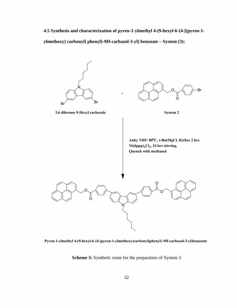
4.5 Synthesis and characterization of pyren-1-ylmethyl 4-(9-hexyl-6-{4-[(pyren-1-
ylmethoxy) carbonyl] phenyl}-9H-carbazol-3-yl) benzoate – System (3): .................... 32
4.6 Photophysical examination of System 3 in solution phase: ...................................... 35
CHAPTER 5…………………………………………………………………………...38
CONCLUSION .............................................................................................................. 38
APPENDIX A: 1H and 13C NMR spectra of compounds ............................................... 40
APPENDIX B: FTIR spectra of compounds .................................................................. 49
LITERATURE CITED: ................................................................................................ 51
vi
LIST OF FIGURES
Figure 2.1: Basic construction of double heterostructure OLED…………….…………..4
Figure 2.2: OLED operation mechanism…………………………...……………………6
Figure 2.3: Layer sequences and energy level diagrams of different device structures….7
Figure 4.1: (a) UV-Vis absorbtion and (b) Fluorescence emission spectra (excited at 350
nm) of System 1………………………………………………………………..……….25
Figure 4.2: Blue light emission of System 1 under UV
irradiation……………….………………………………….…………………………...26
Figure 4.3: (a) UV-Vis absorption and (b) Fluorescence emission spectra (excited at 345
nm) of System 2………………………………………………………………………...30
Figure 4.4: Blue light emission of System 2 under UV
irradiation……………………………………………………………………………….31
Figure 4.5: (a) UV-Vis absorption and (b) Fluorescence emission spectra (excited at 275
nm) of System 3………………………………………………….……………………..35
Figure 4.6: Blue light emission of System 3 under UV
irradiation……………………………………………………………………………….36
Figure 4.7: All the systems emitting different colors under UV
irradiation……………………………………………………………………………….37

vii
LIST OF TABLES
Table 1: Comparison of inorganic LEDs vs OLEDs………….………………………..10

viii
LIST OF SCHEMES
Scheme 1: Synthetic route for the preparation of System (1)…………………………..22
Scheme 2: Synthetic route for the preparation of System (2)……….………………….27
Scheme 3: Synthetic route for the preparation of System (3)…………………………..32
ix
FUSED-MOLECULAR SYSTEMS FOR ORGANIC LIGHT EMITTING DIODES
Avinash Jami December 2015 54 Pages
Directed by: Dr. Hemali Rathnayake, Dr. Edwin Stevens, and Dr. Bangbo Yan
Department of Chemistry Western Kentucky University
Organic light emitting diodes (OLEDs) are electronic devices made by
sandwitching organic light emissive materials between two electrodes. When voltage is
applied across the two conductors, a bright light is generated. The color of the emitting
light depends on the band gap of the semiconducting material. The work described here
focuses on designing and synthesizing narrow band gap molecular systems derived from
fused-arene derivatives for producing organic blue light emitting diodes.
Three molecular systems derived from anthracene, pyrene, and carbazole, were designed
and synthesized. Two molecular systems of anthracen-9-ylmethyl anthracene-9-
carboxylate and pyren-1-ylmethyl 4-bromobenzoate were synthesized through Steglich
esterification reaction and the third, pyren-1-ylmethyl 4-(9-hexyl-6-{4-[(pyren-1-
ylmethoxy) carbonyl] phenyl}-9H-carbazol-3-yl) benzoate was synthesized by Grignard
metathesis followed by Kumada coupling reaction. Structural characterizations were
performed using 1H, 13C NMR and FTIR analysis. Photophysical properties of these
systems were studied in chloroform (CHCl3) solution using UV-visible and
Fluorescence spectroscopies. The absorption and fluorescence emission spectra revealed
the potential applicability of these three systems as blue and blue-green emitters for
OLEDs. The future work of this project will focus on utilizing these three molecular
systems to fabricate OLED devices.
1
CHAPTER 1
INTRODUCTION
1.1 Overview:
Organic light emitting diodes (OLEDs) are light emitting diodes in which the
emissive layer (EML) between the two electrodes is made of organic compounds.
OLEDs can be used in commercial applications like displays and lighting. An organic
green-light emitting diode with some significant characteristics was first reported by
Tang and VanSlyke in 1987 at Eastman Kodak using small molecules like aromatic
diamine (4,4’-(cyclohexane-1,1-diyl)bis(N,N-di-p-tolylaniline)1 and 8-hydroxyquinoline
aluminum (Alq3).1 It was a double-layer structure of organic thin films fabricated by
vapour deposition. Effective injection of charge (electrons and holes) resulted from a
high work function, low sheet resistant and optically transparent ITO (indium-tin-oxide)
anode and a low work function alloy Mg:Ag cathode, respectively. Unique
characteristics of this first prepared OLED included high electroluminescent emission
efficiency, low voltage drive, quick response and ease of fabrication. Organic molecules
and polymers exhibiting electroluminescence in blue, green and red spectral regions
have been developed subsequently. Remarkable research following the discovery of
OLEDs in organic and conjugated polymer thin films2,3 has lead to an immense
literature on them2-4. The EML works on the principle of electroluminescence, i.e
emitting light in response to passage of electric current through it.
Kido, et al., produced the first white OLED in 1993.6 They included red, green
and blue light emitting materials together in their device to produce white light. In 2011,
HoonSeo, et al., demonstrated hybrid organic white-light emitting diodes using N,N1-
2
dicarbazolyl-3,5-benzene and 4,7-diphenyl-1,10-phenanthroline6. In 1992, Grem, et al.,
first reported a blue OLED containing poly (p-phenylene) (PPP).7 Lee, et al.,
synthesized a series of blue fluorescent emitters based on a t-butylated bis
(diarylaminoaryl) anthracene series.8 Through steric hinderance which reduces self-
quenching properties, t-butyl groups, prevent molecular aggregation between blue
emitters8. In 2012, Chen, et al., produced three anthracene derivatives with carbazole
moieties as side groups, 2-tert-butyl-9,10-bis[4-(9-carbazolyl)phenyl]anthracene, 2-tert-
butyl-9,10-bis{4-[3,6-di-tert-butyl-(9-carbazolyl)]phenyl}anthracene and 2-tert-butyl-
9,10-bis{4’-[3,6-di-tert-butyl-(9-carbazolyl)]biphenyl-4-yl}anthracene, to use in blue
OLEDs9. Tang and Vanslyke in 1987 demonstrated the first bright green-light emission
using aluminum tris (8-hydroxyquinolinate) (Alq3) thin film organic layers1. A highly
efficient non-doped green OLED was reported by Ku, et al., by incorporating 9,9-
diarylfluorene terminated 2,1,3-benzothiadiazole (DFBTA).10 This device exhibited
remarkable characteristics, including a luminescence of 12.9 cd/A and an 81% solid
state photoluminescence quantum yield10.

3
1.2 Research goal:
The goal of my research thesis is to develop synthetic procedures to make small
molecular systems based on fused aromatic molecules for OLED applications. In this
thesis, I focus on the synthetic methods, characterization, and photophysical properties
of three systems that are derived from anthracene, pyrene and carbazole. System 1 is an
anthracene based molecular system prepared from an esterification (DCC coupling)
reaction between 9-anthracenemethanol and 9-anthracenecarboxylic acid. System 2 is a
pyrene based molecular system prepared in a similar manner as System 1 utilizing a
DCC coupling reaction between 4-bromobenzoic acid and 1-pyrenemethanol. System 3
is derived from carbazole and pyrene derivatives prepared by Grignard metathesis
followed by a Kumada coupling reaction between System 2 and 3,6 dibromo 9-hexyl
carbazole. Photophysical properties of these three systems will also be discussed to
evaluate their optoelectronic properties in solution. Future work will focus on utilizing
these three molecular systems to evaluate potential applicability for OLEDs.

4
CHAPTER 2
BACKGROUND
2.1 Basic principle of an Organic light-emitting diode (OLED):
An organic light-emitting diode (OLED) is an electric device that emits bright light
when electric current is applied (electroluminescence). A typical organic light emitting
diode is made of series of organic layers sandwiched between two electrodes, a cathode
and an anode, one of which will be transparent. In general, a high work function, low
sheet resistance and optically transparent ITO (indium-tin-oxide) anode and a low work
function metal cathode such as Ca, Mg, Al or their alloys Mg:Ag, Li:Al are used as
electrodes. The layers between the two electrodes include an electron transport layer
(ETL), an emissive layer (EML) and a hole transport layer (HTL).
Figure 2.1: Basic construction of double heterostructure OLED (Eugene Polikarpov and
Mark E. Thompson, 2011).5
5
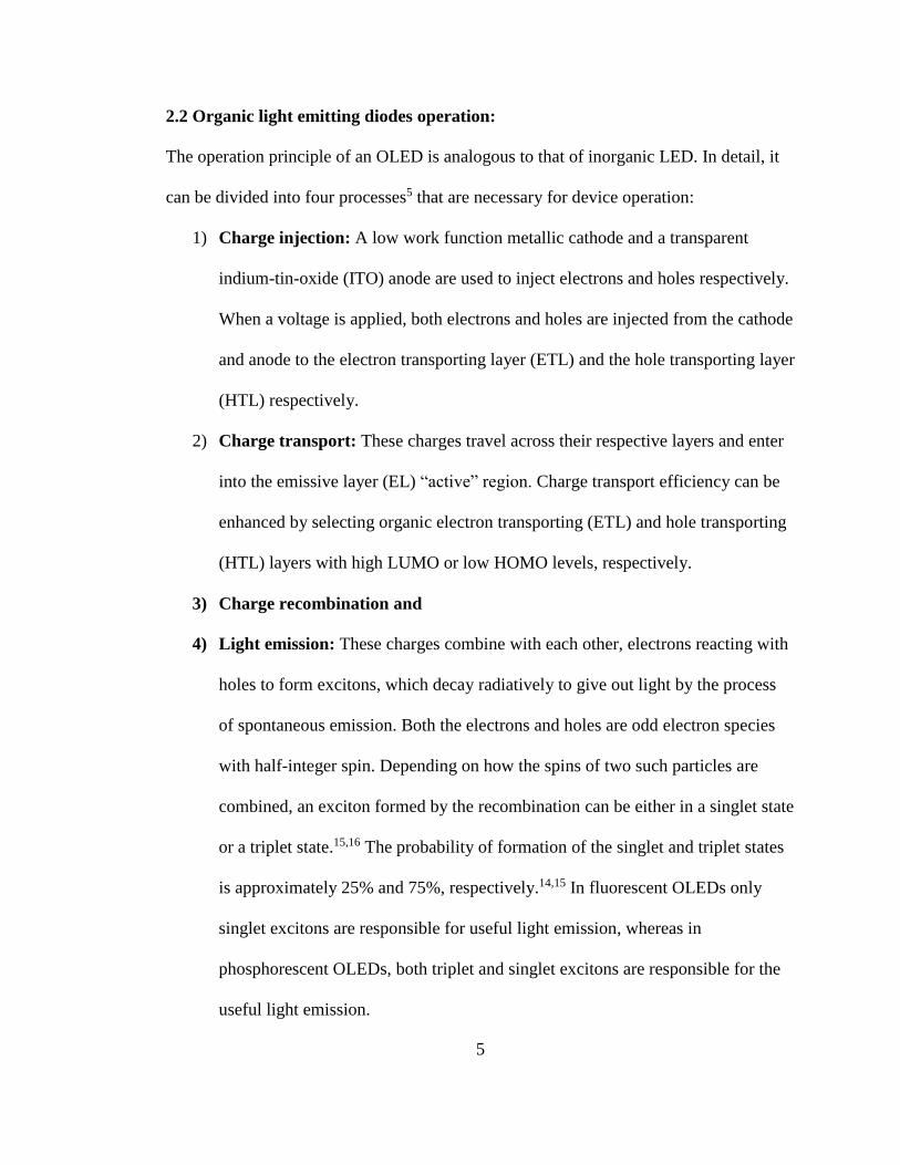
2.2 Organic light emitting diodes operation:
The operation principle of an OLED is analogous to that of inorganic LED. In detail, it
can be divided into four processes5 that are necessary for device operation:
1) Charge injection: A low work function metallic cathode and a transparent
indium-tin-oxide (ITO) anode are used to inject electrons and holes respectively.
When a voltage is applied, both electrons and holes are injected from the cathode
and anode to the electron transporting layer (ETL) and the hole transporting layer
(HTL) respectively.
2) Charge transport: These charges travel across their respective layers and enter
into the emissive layer (EL) “active” region. Charge transport efficiency can be
enhanced by selecting organic electron transporting (ETL) and hole transporting
(HTL) layers with high LUMO or low HOMO levels, respectively.
3) Charge recombination and
4) Light emission: These charges combine with each other, electrons reacting with
holes to form excitons, which decay radiatively to give out light by the process
of spontaneous emission. Both the electrons and holes are odd electron species
with half-integer spin. Depending on how the spins of two such particles are
combined, an exciton formed by the recombination can be either in a singlet state
or a triplet state.15,16 The probability of formation of the singlet and triplet states
is approximately 25% and 75%, respectively.14,15 In fluorescent OLEDs only
singlet excitons are responsible for useful light emission, whereas in
phosphorescent OLEDs, both triplet and singlet excitons are responsible for the
useful light emission.
6
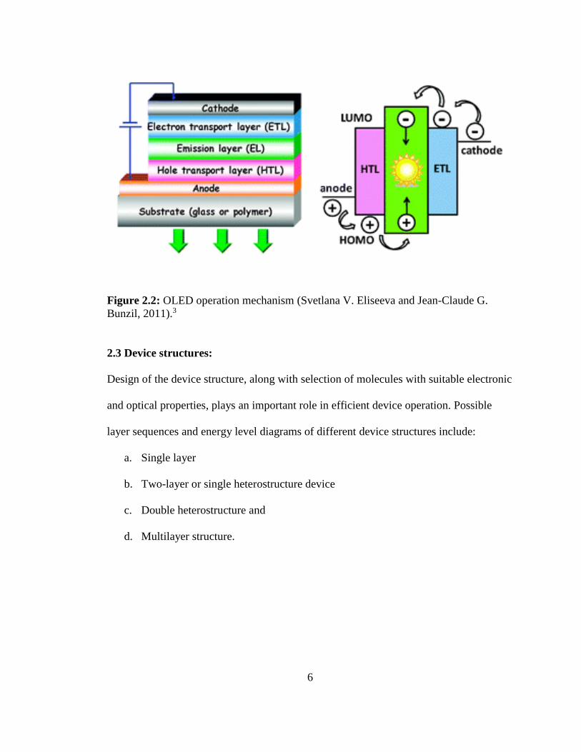
Figure 2.2: OLED operation mechanism (Svetlana V. Eliseeva and Jean-Claude G.
Bunzil, 2011).3
2.3 Device structures:
Design of the device structure, along with selection of molecules with suitable electronic
and optical properties, plays an important role in efficient device operation. Possible
layer sequences and energy level diagrams of different device structures include:
a. Single layer
b. Two-layer or single heterostructure device
c. Double heterostructure and
d. Multilayer structure.

7
Figure 2.3: Layer sequences and energy level diagrams of different device structures.
Both the frontier orbitals, HOMO (highest occupied molecular orbital or valence
band) and LUMO (lowest unoccupied molecular orbital or conduction band) play an
important role in OLED devices. The energy difference between the HOMO and LUMO
levels is known as the HOMO-LUMO gap, and it limits the color of the emitted light.
The different colors emitted from an OLED depends on a type of organic molecule used
in the emissive layer, and the intensity or brightness depends on the amount of current
generated.
2.4 Classification of OLEDs:
OLEDs are fabricated either by using small molecules or polymers28,29.
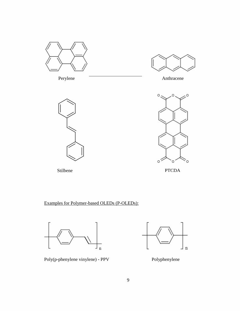
1) Examples of small molecule-based devices (SM-OLED) include tris (8-
hydroxyquinolinato) aluminum (Alq3), BCP (4,7-diphenyl-1,10 phenenthroline),
Diamine (4,4’-(cyclohexane-1,1-diyl)bis(N,N-di-p-tolylaniline), perylene,

8
anthracene, stilbene and PTCDA (3,4,9,10-perylentetracarboxylic dianhybride)
etc.
2) Examples of polymer-based devices (P-OLED) include derivaties of poly(p-
phenylene-vinylene (PPV), polyphenylene, poly(alkylthiophene) and poly(9,9’
dialkyl fluorine), etc
Examples for Small molecule OLEDs (SM-OLEDs):
Alq3 BCP (Bathocuproine)
Diamine
9
Perylene Anthracene
Stilbene
Examples for Polymer-based OLEDs (P-OLEDs):
Poly(p-phenylene vinylene) - PPV Polyphenylene
PTCDA

10
Poly(alkylthiophene) Poly(9, 9’ dialkyl fluorene)
Electrical conductivity of these organic molecules is due to the delocalization of
loosely bound - electrons, which is the result of conjugation over some or all of the
molecule. SM-OLEDs can be fabricated using vacuum deposition under ultrahigh
vacuum conditions whereas P-OLEDs can be applied using spin-coating or even ink-jet
printing techniques.
2.5 Background of OLEDs:
A) Table 1: Comparison of inorganic LEDs vs OLEDs – Advantages, disadvantages,
efficiency and fabrication.
LED (Light emitting diode) OLED (Organic light
emitting diode)
General description Heavy, rigid Thin, flat, lighter and more
flexible
Active layer Inorganic Organic
Backlight Needs backlight Doesn’t need backlight
Power consumption Consumes more power Consumes less power

11
Contrast ratio Low contrast ratio High contrast ratio
Viewing angle Narrow Wide
Moisture Resistant Sensitive
Lifetime High Low
Response time Slow Fast
Processing temperature High Low
Color accuracy Low High
Cost Low cost Expensive
Outdoor performance Good Poor
B) Applications of OLEDs:
a. Solid-state lighting: OLEDs can be used in household lighting, automobiles, etc.
b. Display technologies: OLED is the new technology that is being applied to flat
panel displays like TV’s and smartphones etc.
C) OLED Characterization parameters:
a. Luminescence efficiency: External and internal quantum efficiencies.
i. External quantum efficiency (ηEQE): It is the ratio of photons and electrons
moving out and into the device, respectively. It quantifies conversion efficiency
of electrical energy into optical energy. It can also be defined as the product of
the internal quantum efficiency and light extraction efficiency.
ii. Internal quantum efficiency (ηIQE): It is the ratio of internally generated
photons to the electrons moving into the device. In fluorescent OLEDs, only
12
singlets result in the emission of useful radiation, placing a theoretical limit on
the internal quantum efficiency (the percentage of excitons formed that result in
emission of a photon) of 25%11. However, phosphorescent OLEDs generate light
from both triplet and singlet excitons, allowing the internal quantum efficiency
of such devices to reach nearly 100%12. In general, conjugated polymers have
rod-like rigid structures. These rod-like rigid polymers are susceptible to
aggregation, leading to fluorescenece quenching which results in lower quantum
efficiency.
iii. Light extraction efficiency: It is the ratio of amount of light (fraction of
photons) generated in the device to the amount of light (fraction of photons) that
escapes into free space from the device.
b. Voltage drive: A certain minimum voltage must be reached to overcome the barriers
to injecting charges into the organic materials. The lower the voltage required, the
higher the efficiency of the OLED.
D) Effects of increases in conjugation: An increase in the conjugation of the organic
materials used in the OLEDs leads to the emission of longer wavelength visible light,
moving from blue to red. Conjugation increases the energy of the HOMO (π) and
decreases the energy of the LUMO (π*), so less energy is required for an electronic
transition (π→ π*) in a conjugated system than in a non-conjugated system. In the
presence of more conjugated double bonds in a compound, less energy is required for
the electronic transitions, therefore the longer the wavelength at which the electronic
transition occurs. The λmax increases as the number of conjugated double bonds
13
increases. λmax is the wavelength in the absorbance spectrum at which the absorption of
light is the maximum.
E) Importance of fused aromatic systems as emissive materials: Fused aromatic
molecular systems often have high quantum yields. For fluorescence, it can be defined
as the ratio of number of photons emitted to the number of photons absorbed.
Ф = # photons emitted / # photons absorbed
π - Conjugated molecular systems, because of their high stability and excellent
charge carrier mobility, have drawn considerable interest in the field of organic
electronics and may lead to practical applications17. High charge carrier mobility results
from their lower oxidation potential, high conjugation obtained by fused aromatic rings
and high rigidity favoring improved π-π overlap in the solid state leading to effective
interchain and intrachain charge transport. Changes in molecular packing can also be
induced by ring fusion, such as conversion from less promising herringbone packing to
the preferred π-stacking.
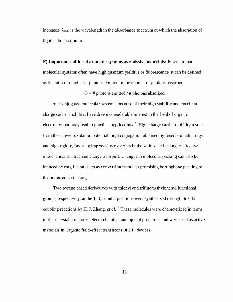
Two pyrene based derivatives with thienyl and trifluomethylphenyl functional
groups, respectively, at the 1, 3, 6 and 8 positions were synthesized through Suzuki
coupling reactions by H. J. Zhang, et al.18 These molecules were characterized in terms
of their crystal structures, electrochemical and optical properties and were used as active
materials in Organic field-effect transistor (OFET) devices.
14
Anthracene (C4H10) is a crystalline solid with an energy band gap of ~ 3.9 eV, low
melting point, and poor electrical conductivity19. Research on single crystal organic
molecules, which include tetracene, pentacene and rubrene molecular crystals is rare20-27.
Acenes having n-linked benzene rings (n=3: anthracene; n=4: tetracene; n=5 pentacene)
facilitate intermolecular overlap of π systems because of their planar shapes enables
efficient crystal packing and prolonged π systems.30
15
CHAPTER 3
EXPERIMENTAL PROCEDURES:
3.1 Materials:
9-Anthracenemethanol, 9-anthracenecarboxylic acid, 4-bromobenzoic acid. 1-
pyrenemethanol, dicyclohexylcarbodiimide (DCC), 4-dimethylaminopyridine (DMAP),
dichloromethane (DCM), pyren-1-ylmethyl 4-bromobenzoate, 3,6-dibromo 9 hexyl
carbazole, tert-butyl magnesium chloride, anhydrous tetrahydrofuran,
bis[(diphenylphosphino)propane]nickel(II) chloride, hexane, chloroform, chloroform-D,
silica gel. All the materials were obtained from Sigma-Aldrich and were used without
any further purification.
3.2 Characterization:
1H and 13C NMR spectra were recorded using a 500 MHz Jeol NMR
spectrometer. IR spectra were recorded using a Perkin Elmer Spectrum One FTIR.
Fluorescence spectra were recorded using a Perkin Elmer LS 55 spectrometer, and UV
spectra were recorded using a Perkin Elmer Lambda 35 spectrometer.
16
3.3 Procedure for the synthesis of anthracen-9-ylmethyl anthracene-9-carboxylate
– System (1):
To a 100 mL two-necked round-bottom flask, 9-anthracenemethanol (0.9 eq, 0.50
g, 2.4 mmol), 9-anthracenecarboxylicacid (1 eq, 0.59 g, 2.6 mmol),
dicyclohexylcarbodiimide (1 eq, 0.49 g) and 4-dimethylaminopyridine (0.08g) were
added. The flask was degassed using argon for 15-30 minutes. Dichloromethane (DCM)
(30 mL) was added to the reaction mixture by syringe through one of the septa forming a
cloudy, bright-yellow colored solution, and it was stirred for 24 hours at room
temperature. The solution flask was wrapped with aluminum foil the entire time to
prevent exposure to light. No further change in the appearance of the solution was
observed, even after 24 hours. The solution was transferred to a 100 mL one necked
round-bottomed flask. Any solid left in the reaction flask was washed using a few mL of
DCM into the original solution. Solvent was extracted from the solution using a
Rotovap, leaving a yellow colored solid to the walls of the flask. A sufficient amount of
DI water was added to the flask, and all the solid was scrapped into it. Now the solution
was filtered using suction filtration for around one hour, yielding a yellow colored solid.
The sample was dried under vaccum for 24 hrs. TLC was performed for the product
using the two starting materials, 9-anthracenemethanol and 9-anthracenecarboxylic acid
in DCM: Hexane solution (3:2). Samples were prepared for TLC by dissolving minute
amounts in DCM that were spotted on a TLC plate. The TLC plate was then placed for a
few minutes inside a jar having a few mL of DCM: Hexane solution. A UV-lamp was
used to observe the spots on the TLC plate. The TLC experiment supported product
17
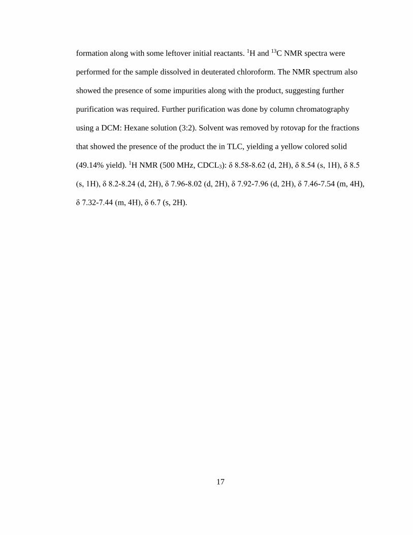
formation along with some leftover initial reactants. 1H and 13C NMR spectra were
performed for the sample dissolved in deuterated chloroform. The NMR spectrum also
showed the presence of some impurities along with the product, suggesting further
purification was required. Further purification was done by column chromatography
using a DCM: Hexane solution (3:2). Solvent was removed by rotovap for the fractions
that showed the presence of the product the in TLC, yielding a yellow colored solid
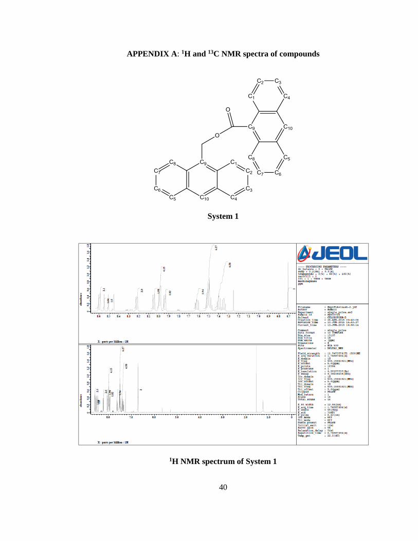
(49.14% yield). 1H NMR (500 MHz, CDCL3): δ 8.58-8.62 (d, 2H), δ 8.54 (s, 1H), δ 8.5
(s, 1H), δ 8.2-8.24 (d, 2H), δ 7.96-8.02 (d, 2H), δ 7.92-7.96 (d, 2H), δ 7.46-7.54 (m, 4H),
δ 7.32-7.44 (m, 4H), δ 6.7 (s, 2H).
18
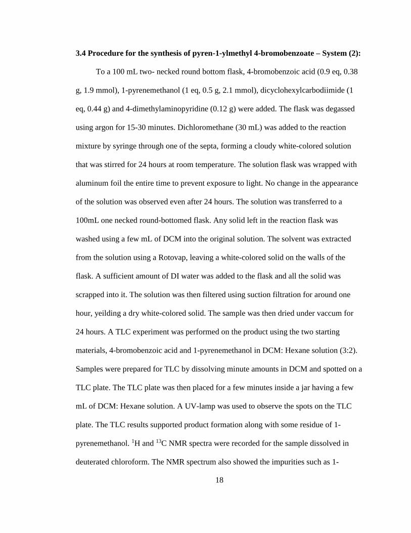
3.4 Procedure for the synthesis of pyren-1-ylmethyl 4-bromobenzoate – System (2):
To a 100 mL two- necked round bottom flask, 4-bromobenzoic acid (0.9 eq, 0.38
g, 1.9 mmol), 1-pyrenemethanol (1 eq, 0.5 g, 2.1 mmol), dicyclohexylcarbodiimide (1
eq, 0.44 g) and 4-dimethylaminopyridine (0.12 g) were added. The flask was degassed
using argon for 15-30 minutes. Dichloromethane (30 mL) was added to the reaction
mixture by syringe through one of the septa, forming a cloudy white-colored solution
that was stirred for 24 hours at room temperature. The solution flask was wrapped with
aluminum foil the entire time to prevent exposure to light. No change in the appearance
of the solution was observed even after 24 hours. The solution was transferred to a
100mL one necked round-bottomed flask. Any solid left in the reaction flask was
washed using a few mL of DCM into the original solution. The solvent was extracted
from the solution using a Rotovap, leaving a white-colored solid on the walls of the
flask. A sufficient amount of DI water was added to the flask and all the solid was
scrapped into it. The solution was then filtered using suction filtration for around one
hour, yeilding a dry white-colored solid. The sample was then dried under vaccum for
24 hours. A TLC experiment was performed on the product using the two starting
materials, 4-bromobenzoic acid and 1-pyrenemethanol in DCM: Hexane solution (3:2).
Samples were prepared for TLC by dissolving minute amounts in DCM and spotted on a
TLC plate. The TLC plate was then placed for a few minutes inside a jar having a few
mL of DCM: Hexane solution. A UV-lamp was used to observe the spots on the TLC
plate. The TLC results supported product formation along with some residue of 1-
pyrenemethanol. 1H and 13C NMR spectra were recorded for the sample dissolved in
deuterated chloroform. The NMR spectrum also showed the impurities such as 1-
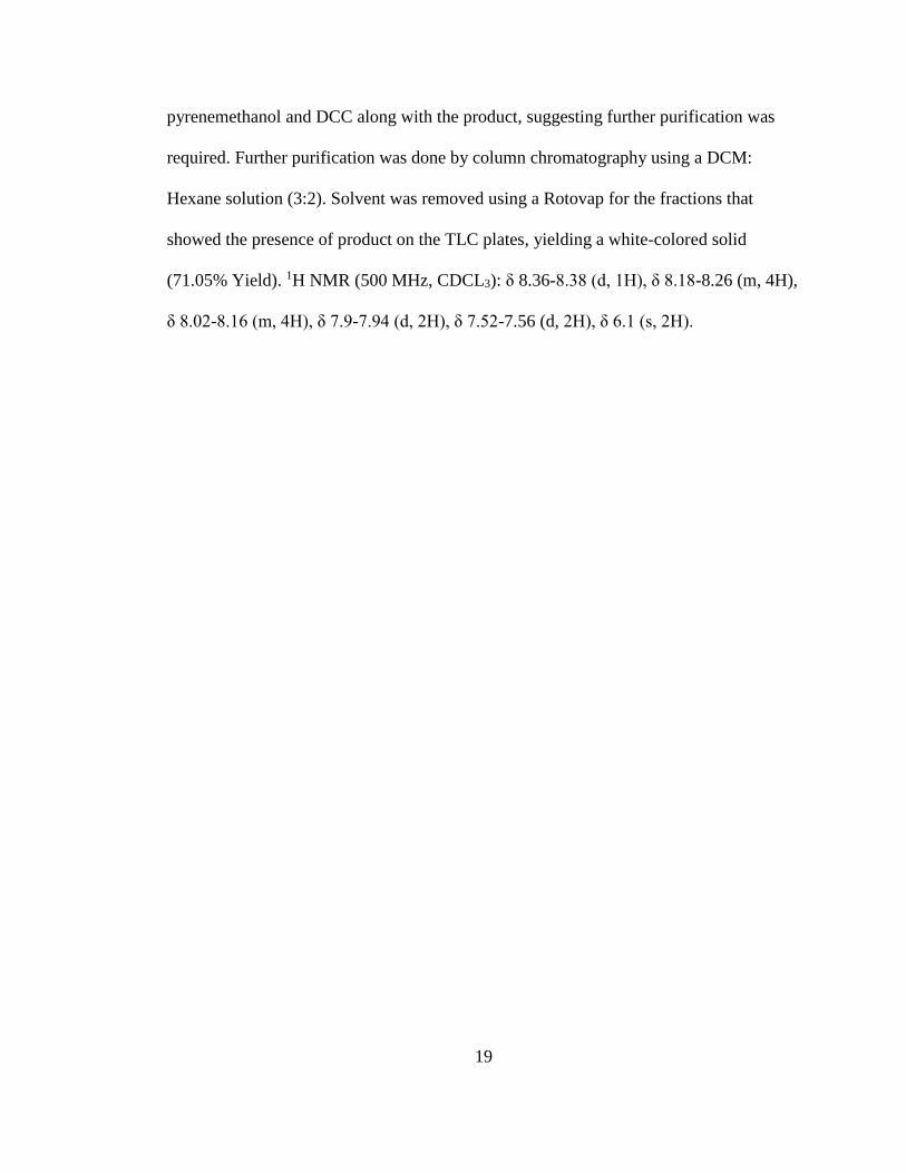
19
pyrenemethanol and DCC along with the product, suggesting further purification was
required. Further purification was done by column chromatography using a DCM:
Hexane solution (3:2). Solvent was removed using a Rotovap for the fractions that
showed the presence of product on the TLC plates, yielding a white-colored solid
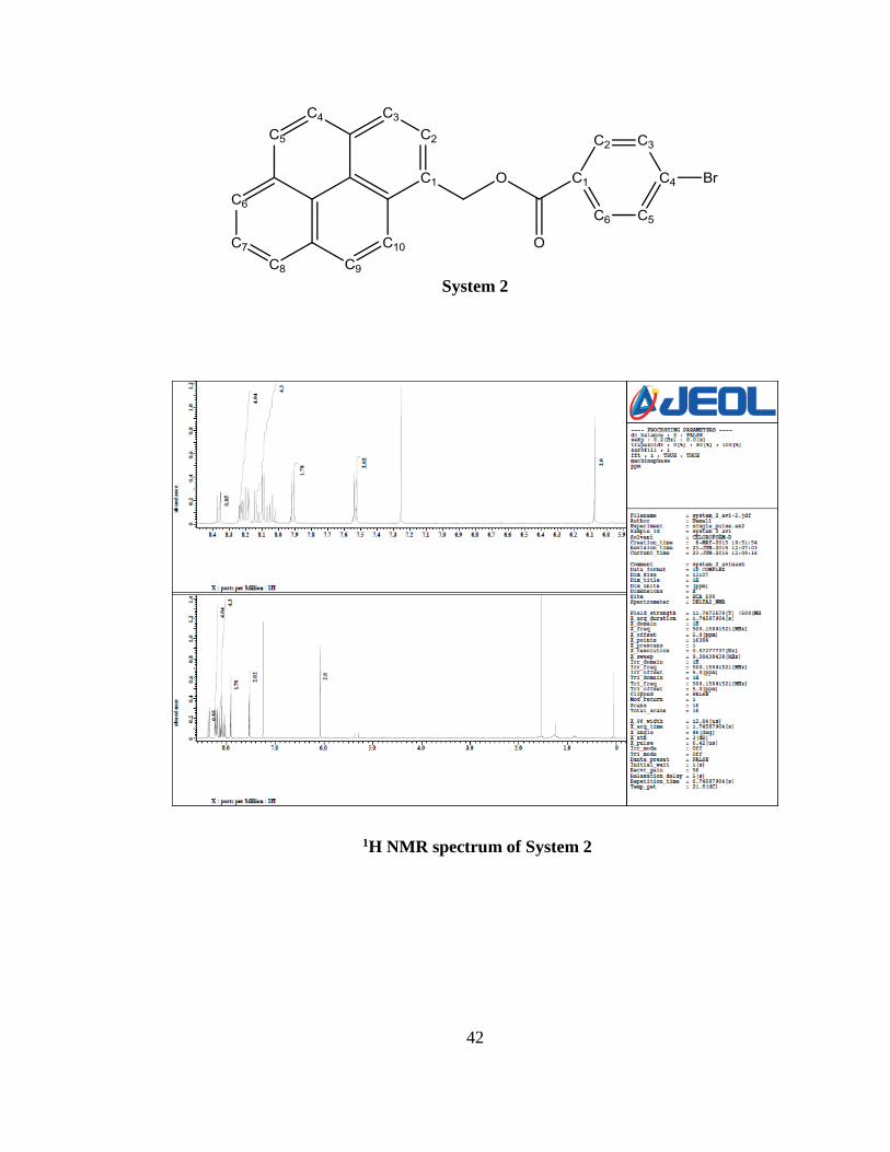
(71.05% Yield). 1H NMR (500 MHz, CDCL3): δ 8.36-8.38 (d, 1H), δ 8.18-8.26 (m, 4H),
δ 8.02-8.16 (m, 4H), δ 7.9-7.94 (d, 2H), δ 7.52-7.56 (d, 2H), δ 6.1 (s, 2H).
20
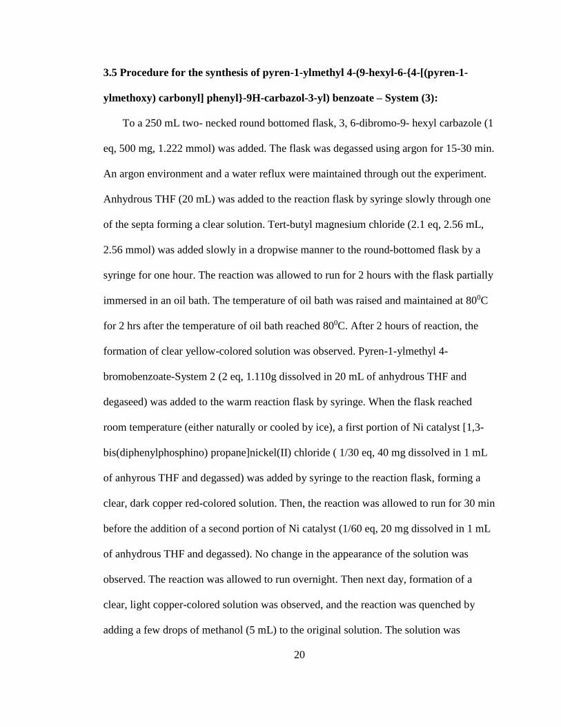
3.5 Procedure for the synthesis of pyren-1-ylmethyl 4-(9-hexyl-6-{4-[(pyren-1-
ylmethoxy) carbonyl] phenyl}-9H-carbazol-3-yl) benzoate – System (3):
To a 250 mL two- necked round bottomed flask, 3, 6-dibromo-9- hexyl carbazole (1
eq, 500 mg, 1.222 mmol) was added. The flask was degassed using argon for 15-30 min.
An argon environment and a water reflux were maintained through out the experiment.
Anhydrous THF (20 mL) was added to the reaction flask by syringe slowly through one
of the septa forming a clear solution. Tert-butyl magnesium chloride (2.1 eq, 2.56 mL,
2.56 mmol) was added slowly in a dropwise manner to the round-bottomed flask by a
syringe for one hour. The reaction was allowed to run for 2 hours with the flask partially
immersed in an oil bath. The temperature of oil bath was raised and maintained at 800C
for 2 hrs after the temperature of oil bath reached 800C. After 2 hours of reaction, the
formation of clear yellow-colored solution was observed. Pyren-1-ylmethyl 4-
bromobenzoate-System 2 (2 eq, 1.110g dissolved in 20 mL of anhydrous THF and
degaseed) was added to the warm reaction flask by syringe. When the flask reached
room temperature (either naturally or cooled by ice), a first portion of Ni catalyst [1,3-
bis(diphenylphosphino) propane]nickel(II) chloride ( 1/30 eq, 40 mg dissolved in 1 mL
of anhyrous THF and degassed) was added by syringe to the reaction flask, forming a
clear, dark copper red-colored solution. Then, the reaction was allowed to run for 30 min
before the addition of a second portion of Ni catalyst (1/60 eq, 20 mg dissolved in 1 mL
of anhydrous THF and degassed). No change in the appearance of the solution was
observed. The reaction was allowed to run overnight. Then next day, formation of a
clear, light copper-colored solution was observed, and the reaction was quenched by
adding a few drops of methanol (5 mL) to the original solution. The solution was
21
transferred to a 100mL one necked round bottomed flask and the solvents were extracted
from the solution using a Rotovap, leaving a very light brown-colored solid to the walls
of the flask. A sufficient amount of DI water was added to the flask and the solid was
scrapped into it. Now the solution was filtered using suction filtration for around one
hour, yeilding a dry light brown-colored solid. The sample was dried under vaccum for
24 hours. A TLC experiment was performed for the product using the two starting
materials 3,6-dibromo-9-hexyl carbazole and pyren-1-ylmethyl 4-bromobenzoate-
System 2 in a DCM:Hexane solution (1:3), which did not confirm the presence of the
product, as there was no clear separation of the spots. 1H and 13C NMR were performed
and they supported product formation by the coupling reaction (73% yield). 1H NMR
500 MHz, CDCL3): δ 8.32-8.4 (d, 2H), δ 8-8.26 (m, 16H, 4H), δ 7.88-7.94 (d, 4H), δ
7.5-7.58 (m, 6H), δ 6.1 (s, 4H), δ 4.2-4.3 (t, 2H), δ 1.8-1.9 (m, 2H), δ 1.2-1.4 (m, 6H), δ
0.8-0.9 (t, 3H).
22
CHAPTER 4
RESULTS AND DISCUSSION
4.1 Synthesis and Characterization of anthracen-9-yl methyl anthracene-9-
carboxylate – System (1):
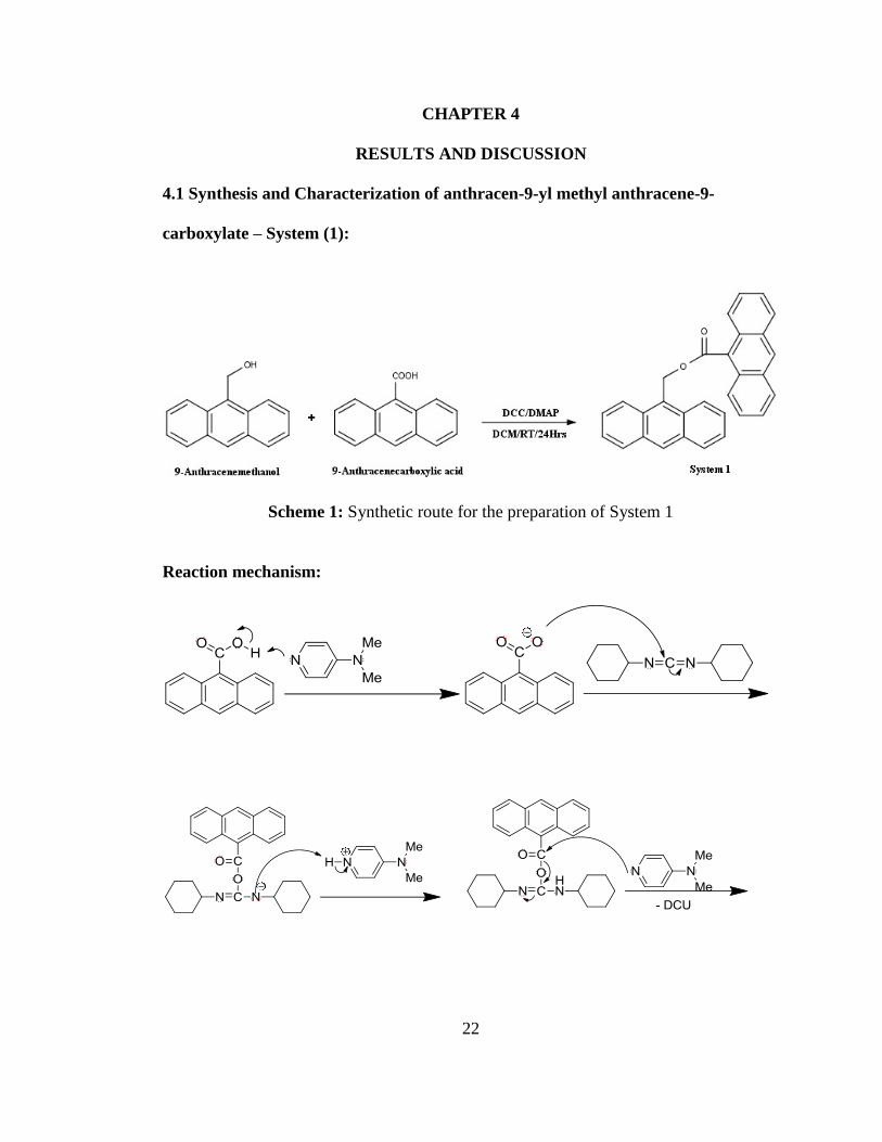
Scheme 1: Synthetic route for the preparation of System 1
Reaction mechanism:

23
As depicted in Scheme 1, System 1 was prepared by using the well known
‘Steglich esterification’ method, by reacting 9-anthracenemethanol with 9-
anthracenecarboxylic acid in the presence of dicyclohexylcarbodiimide (DCC),
dimethylaminopyridine (DMAP) and dichloromethane (DCM) under an argon
environment at room temperature to yield a yellowish solid crude product. In the
reaction mechanism, DMAP acts as an acyl group transferring catalyst and strong
nucleophile, DCC acts as a coupling reagent by activating carboxylic acid to further
reaction, and DCM acts as a solvent. The product formed was further purified by column
chromatography using a DCM: Hexane solution (3:2) to give a yellow powdered solid in
49.14% yield. The structure of the product was confirmed by 1H NMR and the presence
of the carbonyl group is confirmed by 13C NMR and FTIR. In the 1H NMR, the peaks at
δ 8.5 (s, 1H), δ 8.24-8.20 (d, 2H), δ 7.96-7.92 (d, 2H), and δ 7.44 -7.32 (m, 4H) confirm

24
the presence of the methoxy anthracene unit. The peaks at δ 8.8-8.4 (d, 2H), δ 8.62-8.58
(d, 2H), δ 8.54 (s, 1H) and δ 7.54-7.46 (m, 4H) confirm the presence of the carboxy
anthracene unit. The peak at δ 6.7 (s) clearly indicates that the esterification was
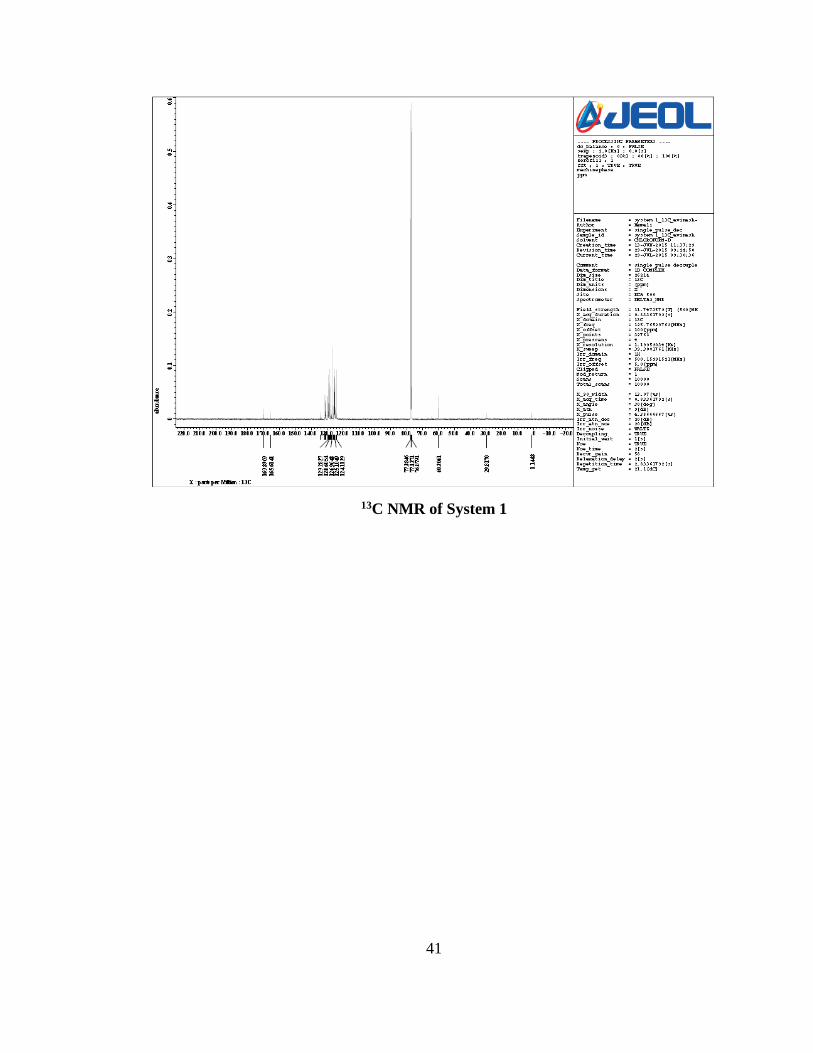
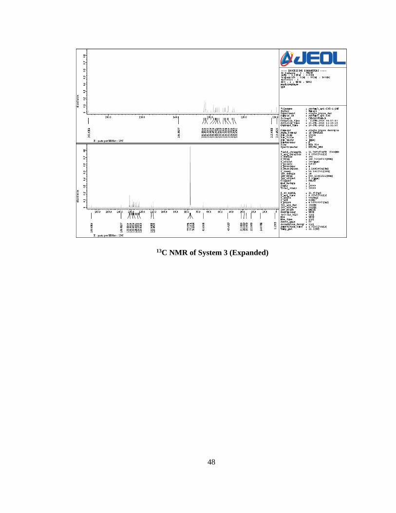
successful for the formation of the product. In the 13C NMR, the peak at δ 169.89
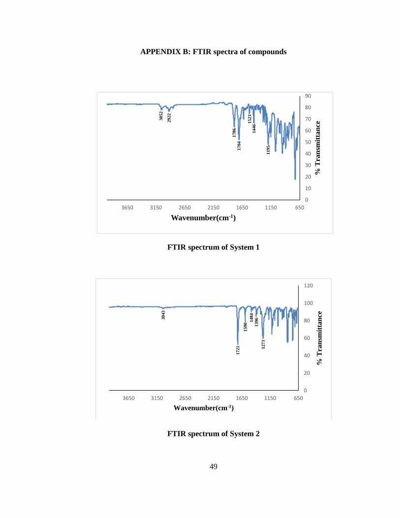
confirms the presence of carbonyl functional group. FTIR also supports the formation of
the ester bond, with the peaks at 1704 cm-1 and 1786 cm-1 that correspond to the
carbonyl stretching. The peak at 1195 cm-1 correspond to the ester C-O stretching. The
peak at 3052 cm-1 correspond to aromatic C-H stretching. The peak at 1523 cm-1 agrees
with the expected aromatic C=C stretching. The peak at 2922 cm-1 and 1446 cm-1
corresponds to aliphatic C-H bond stretching.
25
4.2 Photophysical studies of System 1 in solution phase:
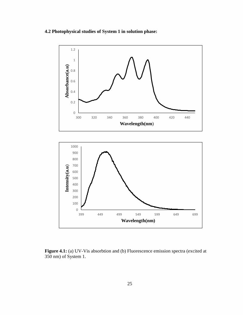
Figure 4.1: (a) UV-Vis absorbtion and (b) Fluorescence emission spectra (excited at
350 nm) of System 1.
0
100
200
300
400
500
600
700
800
900
1000
399 449 499 549 599 649 699
Inte
nsi
ty(a
.u)
Wavelength(nm)
0
0.2
0.4
0.6
0.8
1
1.2
300 320 340 360 380 400 420 440
Ab
sorb
an
ce(a
.u)
Wavelength(nm)
26
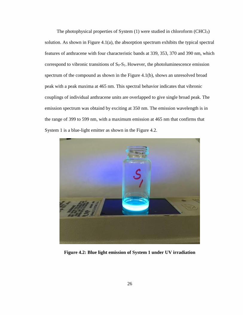
The photophysical properties of System (1) were studied in chloroform (CHCl3)
solution. As shown in Figure 4.1(a), the absorption spectrum exhibits the typical spectral
features of anthracene with four characteristic bands at 339, 353, 370 and 390 nm, which
correspond to vibronic transitions of S0-S1. However, the photoluminescence emission
spectrum of the compound as shown in the Figure 4.1(b), shows an unresolved broad
peak with a peak maxima at 465 nm. This spectral behavior indicates that vibronic
couplings of individual anthracene units are overlapped to give single broad peak. The
emission spectrum was obtaind by exciting at 350 nm. The emission wavelength is in
the range of 399 to 599 nm, with a maximum emission at 465 nm that confirms that
System 1 is a blue-light emitter as shown in the Figure 4.2.
Figure 4.2: Blue light emission of System 1 under UV irradiation

27
4.3 Synthesis and Characterization of pyren-1-ylmethyl 4-bromobenzoate – System
(2):
Scheme 2: Synthetic route for the preparation of System 2
Reaction mechanism:
28
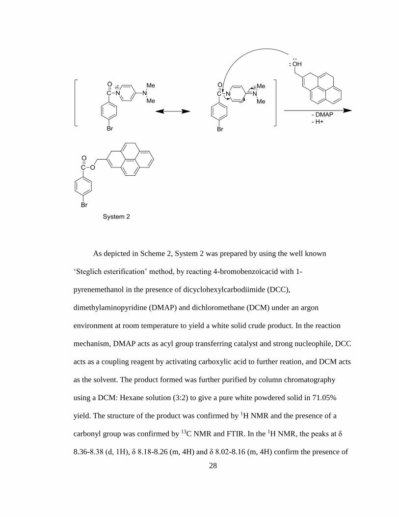
As depicted in Scheme 2, System 2 was prepared by using the well known
‘Steglich esterification’ method, by reacting 4-bromobenzoicacid with 1-
pyrenemethanol in the presence of dicyclohexylcarbodiimide (DCC),
dimethylaminopyridine (DMAP) and dichloromethane (DCM) under an argon
environment at room temperature to yield a white solid crude product. In the reaction
mechanism, DMAP acts as acyl group transferring catalyst and strong nucleophile, DCC
acts as a coupling reagent by activating carboxylic acid to further reation, and DCM acts
as the solvent. The product formed was further purified by column chromatography
using a DCM: Hexane solution (3:2) to give a pure white powdered solid in 71.05%
yield. The structure of the product was confirmed by 1H NMR and the presence of a
carbonyl group was confirmed by 13C NMR and FTIR. In the 1H NMR, the peaks at δ
8.36-8.38 (d, 1H), δ 8.18-8.26 (m, 4H) and δ 8.02-8.16 (m, 4H) confirm the presence of
29
a pyrene unit. The peaks at δ 7.9-7.94 (d, 2H) and δ 7.52-7.56 (d, 2H) confirm the
presence of the bromobenzene unit. The peak at δ 6.1 (s) clearly indicates that the
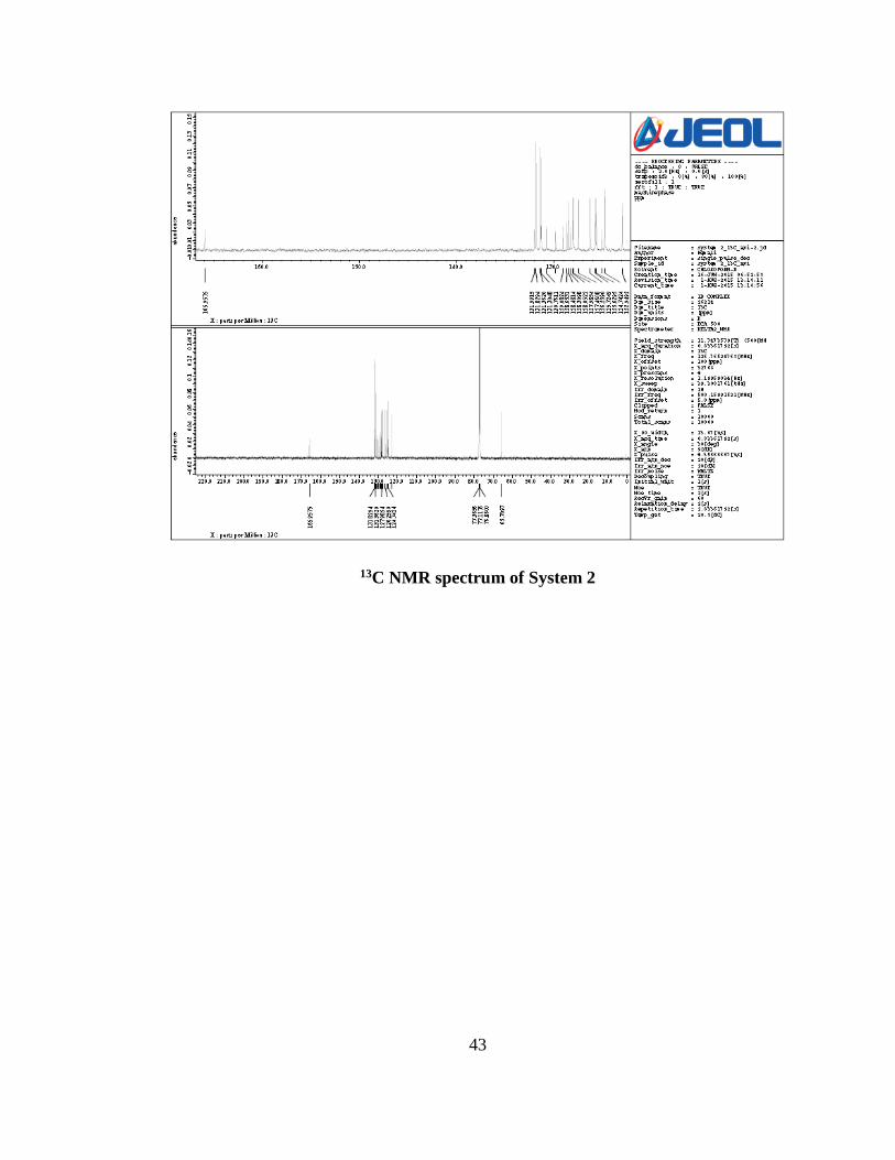
esterification was successful for the formation of the product. In the 13C NMR, the peak
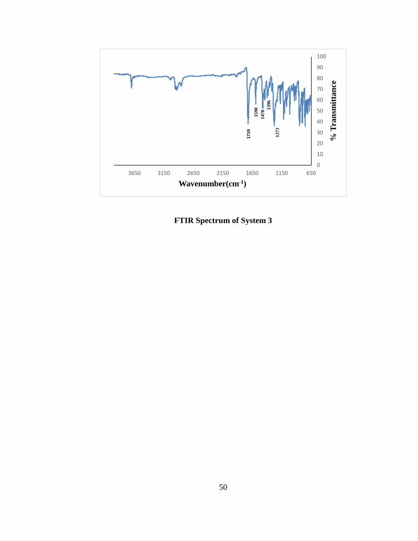
at δ 165.95 confirms the presence of a carbonyl functional froup. FTIR also supports the
formation of the ester bond with the peak at 1721 cm-1 that corresponds to carbonyl
(C=O) stretching. The peak at 1273 cm-1 correspond to the ester C-O stretching. The
peak at 3043 cm-1 corresponds to aromatic C-H stretching. The peaks at 1590 cm-1 and
1484 cm-1 agree with the expected aromatic C=C stretching. The peak at 1396 cm-1
corresponds to aliphatic C-H bond stretching.
30
4.4 Photophysical examination of System 2 in solution phase:
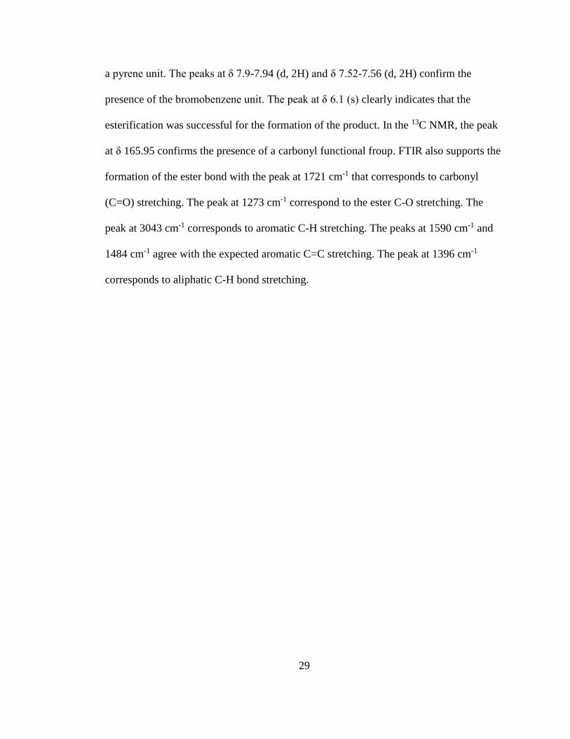
Figure 4.3: (a) UV-Vis absorption and (b) Fluorescence emission spectra (excited at
345 nm) of System 2.
0
0.1
0.2
0.3
0.4
0.5
0.6
0.7
0.8
240 260 280 300 320 340 360 380 400
Ab
sorb
an
ce(a
.u)
Wavelength(nm)
0
50
100
150
200
250
300
350
400
350 400 450 500 550 600
Inte
nsi
ty(a
.u)
Wavelength(nm)
31
The photophysical properties of System (2) were studied in chloroform (CHCl3)
solution. As shown in the Figure 4.3(a), the absorption spectrum exhibits typical
spectral features characteristic of pyrene, with two sets of peaks in the range of 260 to
360 nm. Two characteristic bands at 267 and 277 nm from one set, which correspond to
S0-S2 vibronic transitions. Three characteristic bands are observed at 316, 329 and 346
nm from set two, which correspond to S0-S1 vibronic transitions. The
photoluminescence emission spectrum of the System (2) as shown in the Figure 4.3(b),
shows a maximum emission at 377 nm with two low energy shoulders at 396 and 416
nm. The emission spectrum was obtained by exciting at 345 nm, which corresponds to
the 0-0 trasition. The emission wavelength in the range of 360 to 450 nm confirms that
System 2 is a blue-light emitter, as shown in Figure 4.4.
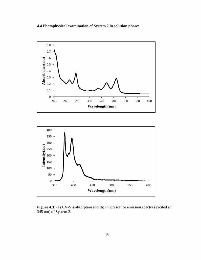
Figure 4.4: Blue light emission of System 2 under UV irradiation.
32
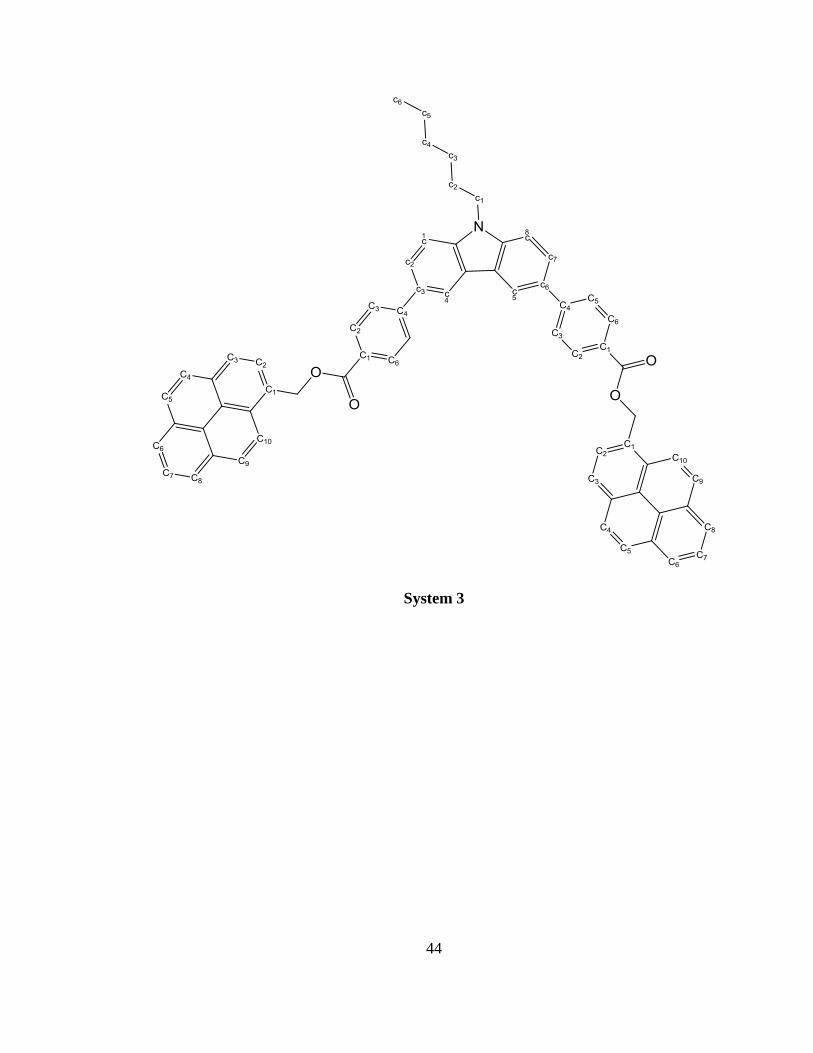
4.5 Synthesis and characterization of pyren-1-ylmethyl 4-(9-hexyl-6-{4-[(pyren-1-
ylmethoxy) carbonyl] phenyl}-9H-carbazol-3-yl) benzoate – System (3):
Scheme 3: Synthetic route for the preparation of System 3
33
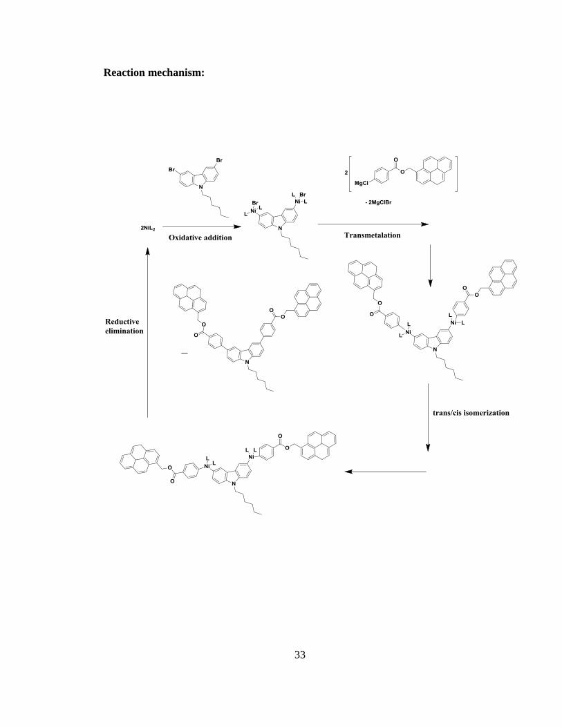
Reaction mechanism:
34
As depicted in Scheme 3, System 3 was prepared by using the Kumada coupling
method, by reacting pyren-1-ylmethyl 4-bromobenzoate with 3,6 dibromo 9 hexyl
carbazole in the presence of tert-Butylmagnesium chloride, Ni catalyst [1,3-
bis(diphenylphosphino) propane]nickel(II) chloride and anhydrous THF under an argon
environment to yield a light brown colored solid crude product in 73% yield. The
mechanism shows the sequence of steps (oxidative addition, transmetalation, trans/cis
isomerization and reductive elimination respectively) undergone by the reactants to form
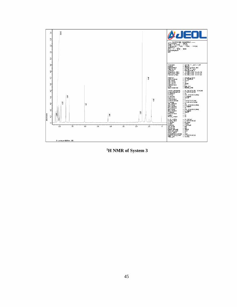
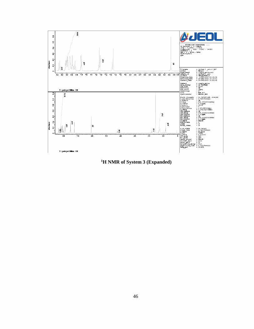
the required product. The structure of the product was confirmed by 1H-NMR and the
presence of carbonyl group was confirmed by 13C NMR and FTIR. In the 1H NMR, the
peaks at δ 8.32-8.4 (d, 2H) and δ 8-8.26 (m, 16H) confirm the presence of two pyrene
units. Peaks at δ 8-8.26 (m, 4H) and δ 7.88-7.94 (d, 4H) confirm the presence of two
benzene units. The peak at δ 7.5-7.58 (m, 6H) confirms the presence of the carbazole
unit. The peak at δ 6.1 (s, 4H) confirms the presence of methylene hydrogens from both
the sides. Peaks at δ 4.2-4.3 (t, 2H), δ 1.8-1.9 (m, 2H), δ 1.2-1.4 (m, 6H) and δ 0.8-0.9 (t,
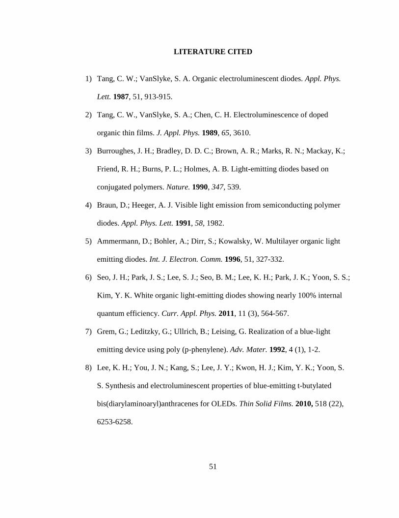
3H) confirm the presence of a hexyl chain. In the 13C NMR, the peak at δ 165.93
confirms the presence of the carbonyl functional group. The FTIR also supports the
formation of the ester bond with peaks at 1719 cm-1 that correspond to carbonyl
stretching. The peak at 1590 cm-1 and 1470 cm-1 agrees with aromatic C=C stretching.
The peak at 1396 cm-1 corresponds to aliphatic C-H bond stretching. Peak at 1273 cm-1
correspond to the ester C-O stretching.

35
4.6 Photophysical examination of System 3 in solution phase:
Figure 4.5: (a) UV-Vis absorption and (b) Fluorescence emission spectra (excited at
275 nm) of System 3.
0
50
100
150
200
250
300
297 347 397 447 497
Inte
nsi
ty(a
.u)
Wavelength(nm)
0
0.2
0.4
0.6
0.8
1
1.2
238 258 278 298 318 338 358 378
Ab
sorb
an
ce(a
.u)
Wavelength(nm)
System 3
3,6-dibromo-9-hexylcarbazole

36
The photophysical properties of System (3) were studied in chloroform solution. As
shown in Figure 4.5(a), the absorption spectrum exhibits typical spectral features
characteristic of pyrene, with two sets of peaks in the wavelength range of 260 to 360
nm. Two characteristic bands at 268 and 278 nm from one set, correspond to S0-S2
vibronic transitions. Three characteristic bands at 316, 330 and 346 nm from set two,
correspond to S0-S1 vibronic transitions. Absorption peaks from carbazole were not
clearly resolved since they were merged with the pyrene spectrum. The
photoluminescence emission spectrum of System (3), as shown in Figure 4.5(b), shows a
maximum emission at 377 nm, with two energy shoulders at 397 and 417 nm. Emission
peaks from carbazole were not clearly resolved since they were mergerd with the pyrene
spectrum. The emission spectrum was obtaind by exciting at 275 nm. The emission
wavelength in the range of 350 to 497 nm confirms that System (3) is a sky blue-light
emitter, as shown in Figure 4.6.
Figure 4.6: Blue light emission of System 3 under UV irradiation
37
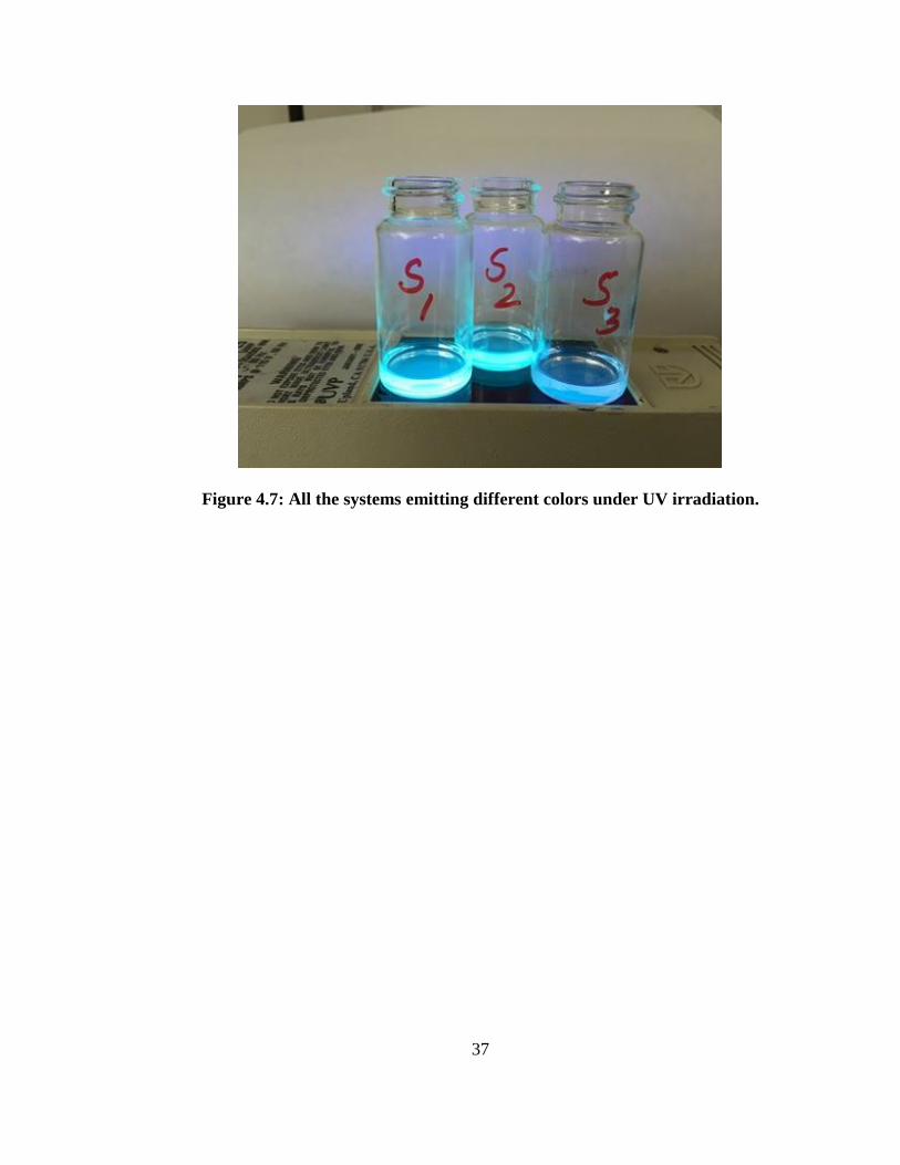
Figure 4.7: All the systems emitting different colors under UV irradiation.
38
CHAPTER 5
CONCLUSION
The main objective of this thesis was to synthesize fused molecular systems that
can be efficiently used in the active layer of OLEDs.
In conclusion, three fused molecular systems, anthracen-9-ylmethyl anthracene-9-
carboxylate (System (1) by Steglich esterification reaction), pyren-1-ylmethyl 4-
bromobenzoate (System (2) by Steglich esterification reaction) and pyren-1-ylmethyl 4-
(9-hexyl-6-{4-[(pyren-1-ylmethoxy) carbonyl] phenyl}-9H-carbazol-3-yl) benzoate
(System (3) by Grignard metathesis followed by a Kumuda coupling reaction) based on
anthracene, pyrene and carbazole, respectively, were synthesiszed and purified. System
(1) showed absorbances of anthracene corresponding to S0-S1 vibronic transitions and a
maximum emission from irradiation at 350 nm was observed at 465 nm in the
wavelength range of 399 to 599 nm, which confirms the emission of blue light. System
(2) showed absorbances of pyrene corresponding to S0-S1 and S0-S2 vibronic transitions,
and a maximum emission from irradiation at 345 nm was observed at 377 nm and 396
nm in the wavelength range of 360 to 450 nm, which confirms the emission of blue
light. System (3) showed absorbances of pyrene corresponding to S0-S1 and S0-S2
vibronic transitions, and a maximum emission from irradiation at 275nm was observed
at 377 nm and 397 nm, which confirms the emission of sky blue light. Their structural
properties were confirmed using 1H NMR, 13C NMR, FTIR spectroscopies. Their
photophysical properties were studied using UV-visible and fluorescenece

39
spectroscopies in solution. Future work will be focusing on utilizing these molecular
systems in making OLEDs and testing their characteristics.
40
APPENDIX A: 1H and 13C NMR spectra of compounds
System 1
1H NMR spectrum of System 1
41
13C NMR of System 1
42
System 2
1H NMR spectrum of System 2
43
13C NMR spectrum of System 2
44
System 3
45
1H NMR of System 3
46
1H NMR of System 3 (Expanded)

47
13C NMR of System 3
48
13C NMR of System 3 (Expanded)
49
APPENDIX B: FTIR spectra of compounds
FTIR spectrum of System 1
FTIR spectrum of System 2
0
10
20
30
40
50
60
70
80
90
650115016502150265031503650
% T
ran
smit
tan
ce
Wavenumber(cm-1)
1786
1704
1523
1446
1195
3052
2922
0
20
40
60
80
100
120
650115016502150265031503650
% T
ran
smit
tan
ce
Wavenumber(cm-1)
30
43
172
1 12
73
15
90
14
84
13
96
50
FTIR Spectrum of System 3
0
10
20
30
40
50
60
70
80
90
100
650115016502150265031503650
% T
ran
smit
tan
ce
Wavenumber(cm-1)
1719
1590
1470
1396
1273
51
LITERATURE CITED
1) Tang, C. W.; VanSlyke, S. A. Organic electroluminescent diodes. Appl. Phys.
Lett. 1987, 51, 913-915.
2) Tang, C. W., VanSlyke, S. A.; Chen, C. H. Electroluminescence of doped
organic thin films. J. Appl. Phys. 1989, 65, 3610.
3) Burroughes, J. H.; Bradley, D. D. C.; Brown, A. R.; Marks, R. N.; Mackay, K.;
Friend, R. H.; Burns, P. L.; Holmes, A. B. Light-emitting diodes based on
conjugated polymers. Nature. 1990, 347, 539.
4) Braun, D.; Heeger, A. J. Visible light emission from semiconducting polymer
diodes. Appl. Phys. Lett. 1991, 58, 1982.
5) Ammermann, D.; Bohler, A.; Dirr, S.; Kowalsky, W. Multilayer organic light
emitting diodes. Int. J. Electron. Comm. 1996, 51, 327-332.
6) Seo, J. H.; Park, J. S.; Lee, S. J.; Seo, B. M.; Lee, K. H.; Park, J. K.; Yoon, S. S.;
Kim, Y. K. White organic light-emitting diodes showing nearly 100% internal
quantum efficiency. Curr. Appl. Phys. 2011, 11 (3), 564-567.
7) Grem, G.; Leditzky, G.; Ullrich, B.; Leising, G. Realization of a blue-light
emitting device using poly (p-phenylene). Adv. Mater. 1992, 4 (1), 1-2.
8) Lee, K. H.; You, J. N.; Kang, S.; Lee, J. Y.; Kwon, H. J.; Kim, Y. K.; Yoon, S.
S. Synthesis and electroluminescent properties of blue-emitting t-butylated
bis(diarylaminoaryl)anthracenes for OLEDs. Thin Solid Films. 2010, 518 (22),
6253-6258.
52
9) Chen, Y. H.; Lin, S. L.; Chang, Y. C.; Chen, Y. C.; Lin, J. T.; Lee, R. H.; Kuo,
W. J.; Jeng, R. J. Efficient non-doped blue light emitting diodes based on novel
carbazole-substituted anthracene derivatives. Org. Electron. Physics. Mater.
Appl. 2012, 13 (1), 43-52.
10) Yu, K. S.; Chen, C. L.; Yi, H. W.; Wei, Y. S.; Cheng, T. T.; Tsung, W. K. Novel
bis(fluorenyl) benzothiadiazole-cored carbazole dendrimers as highly efficient
solution-processed non-doped green emitters for organic light-emitting diodes. J
Mater Chem. 2009, 19, 773-80.
11) Tsutsui, T.; Yang, M. J.; Yahiro, M.; Nakamura, K.; Watanable, T.; Tsuji, T.;
Fukuda, Y.; Wakimoto, T.; Miyaguchi, S. High quantum efficiency in organic
light-emitting devices with iridium-complex as a triplet emissive center.
Japanese Journal of Applied Physics. 1999, 38: L1502-L1504.
12) Adachi, C.; Baldo, M. A.; Thompson, M. E.; Forrest, S. R. Nearly 100% internal
phosphorescence efficiency in an organic light-emitting device. Journal of
Applied Physic. 2011, 90 (10): 5048.
13) Brown, A. R.; Pichler, K.; Greenham, N. C.; Bradley, D. D. C.; Friend, R. H.;
Holmes, A. B. Optical spectroscopy of triplet excitons and charged excitations in
poly (p-phenylenevinylene) light-emitting diodes. Chemical Physics Letters.
1993, 210, 61-66.
14) Baldo, M. A.; O’Brien, D. F.; Thompson, M. E.; Forrest, S. R. Excitonic singlet-
triplet ratio in a semiconducting organic thin film. Physical review B. 1999, 60
(20), 14422-14428.

53
15) Segal, M.; Baldo, M. A.; Holmes, R. J.; Forrest, S. R.; Soos, Z. G. Excitonic
singlet-triplet ratios in molecular and polymeric organic materials. Physical
Review B: Condensed Matter and Materials Physics 2003, 68, 075211/1.
16) Eliseeva, S. V.; Bunzli, J. C. G. Rare earths: jewels for functional materials of
the future. New J. Chem. 2011, 35 (6), 1165.
17) Yan, H.; Chen, Z.; Zheng, Y.; Newman, C.; Quinn, J. R.; Dotz, F.; Kastler, M.;
Facchetti, A. A high-mobility electron-transporting polymer for printed
transistors. Nature. 2009, 457 (7230), 679-686.
18) Zhang, H. J.; Wang, Y.; Shao, K. Z.; Liu, Y. Q.; Chen, S. Y.; Qui, W. F.; Sun, X.
B.; Qi, T.; Ma, Y. Q.; Yu, G.; Su, Z. M.; Zhu, D. B. Pyrene based conjugated
materials: synthesis, characterization and electroluminescent properties. Chem.
Commun., 2006, 755.
19) Pope, M.; Swenberg, C. E. Electronic processes in Organic Crystals and
Polymers, 2nd ed; Oxford University Press: New York, 1999.
20) De Boer, R. W. I.; Klapwijk, T. M.; Morpurgo, A. F. Field-effect transistors on
tetracene single crystals. Appl. Phys. Lett. 2003, 83 (21), 4345-4347.
21) De Boer, R. W. I.; Jochemsen, M.; Klapwijik, T. M.; Morpurgo, A. F.; Niemax,
J. A.; Tripathi, A. K.; Pflaum, J. J. Space charge limited transport and time of
flight measurements in tetracene single crystals: A comparative study. Appl.
Phys. 2006, 95, 1196.
22) Takeya, J.; Goldman, C.; Hass, S.; Pernstich, K. P.; Ketterer, B.; Batlogg, B.
Field-induced charge transport at the surface of pentacene single crystals: A

54
method to study charge dynamics of two-dimensional electron systems in
organic crystals. J. Appl. Phys. 2003, 94 (9), 5800.
23) Butko, V. Y.; Chi, X.; Lang, D. V.; Ramirez, A. P. Field-effect transistor on
pentacene single crystal. Appl. Phys. Lett. 2003, 83 (23), 4773-4775.
24) Budko, V. Y.; Chi, X.; Rammirez, A. P. Free-standing tetracene single crystal
field effect transistor. Solid State Commun. 2003, 128, 431.
25) Pozdrov, V.; Pudalov, V. M.; Gershenson, M. E. Field-effect mobility anisotropy
in PDA-PTS single crystals. Appl. Phys. Lett. 2003, 82, 1739.
26) Pozdrov, V.; Sysoev, S. E.; Loginova, E.; Pudalov, V. M.; Gershenson, M. E.
Mobility studies of field-effect transistor structures based on anthracene single
crystals. Appl. Phys. Lett. 2003, 83, 3504.
27) Sundar, V. C.; Zaumseil, J.; Pozdrov, V.; Menard, E.; Willett, R.; Someya, T.;
Gershenson, M. E.; Rogers, J. A. Elastomeric transistor stamps: Reversible
probing of charge transport in organic crytslas. Science. 2004, 303, 1644.
28) Hung, L. S.; Chen, C. H. Recent progress of molecular organic
electroluminescent materials and devices. Mater. Sci. Eng., R. 2002, 39, 143-
222.
29) Akcelrud, L. Electroluminescent properties. Prog. Polym. Sci. 2003, 28, 875-
962.
30) Gundlach, D. J.; Klauk, H.; Cheraw, C. D.; Kuo, C. C.; Huang, J. R.; Jackson, T.
N. Pentacene organic thin-film transistors for circuit and display applications.
Proc. IEDM 99, 1999, 111.

![OLED: Form Follows Function for Digital Displays - cdw.com · DISPLAY TECHNOLOGY OLED is an entirely new display category ... The new Organic Light-Emitting Diode ... [provides] flexible](https://img.dokumen.tips/doc/110x75/5b7ac9bd7f8b9ab87f8cb21c/oled-form-follows-function-for-digital-displays-cdwcom-display-technology.jpg)


![Perovskite Light-Emitting Diodesjultika.oulu.fi/files/nbnfioulu-202012173371.pdf · OA oleylamine ODEA 2,2'-[oxybis(ethyleneoxy)]diethylamine OLED organic light-emitting diode PAA](https://img.dokumen.tips/doc/110x75/61488a212918e2056c22c16e/perovskite-light-emitting-oa-oleylamine-odea-22-oxybisethyleneoxydiethylamine.jpg)