Embed Size (px)
Citation preview
Veljko Samardzic ME-215 Engineering Materials and Processes
Fundamentals of
Machining/Orthogonal Machining
Chapter 20
Veljko Samardzic ME-215 Engineering Materials and Processes
20.1 Introduction

Veljko Samardzic ME-215 Engineering Materials and Processes
FIGURE 20-1 The
fundamental inputs and
outputs to machining
processes.

Veljko Samardzic ME-215 Engineering Materials and Processes
20.2 Fundementals
Veljko Samardzic ME-215 Engineering Materials and Processes
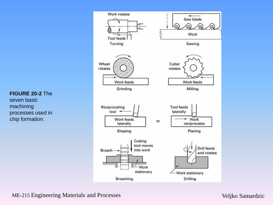
FIGURE 20-2 The
seven basic
machining
processes used in
chip formation.

Veljko Samardzic ME-215 Engineering Materials and Processes
FIGURE 20-3 Turning a
cylindrical workpiece on a
lathe requires you to
select the cutting speed,
feed, and depth of cut.
Veljko Samardzic ME-215 Engineering Materials and Processes
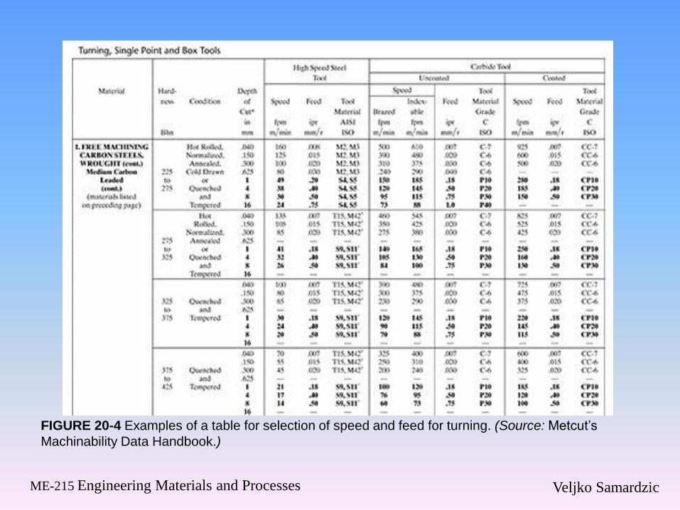
FIGURE 20-4 Examples of a table for selection of speed and feed for turning. (Source: Metcut’s
Machinability Data Handbook.)
Veljko Samardzic ME-215 Engineering Materials and Processes
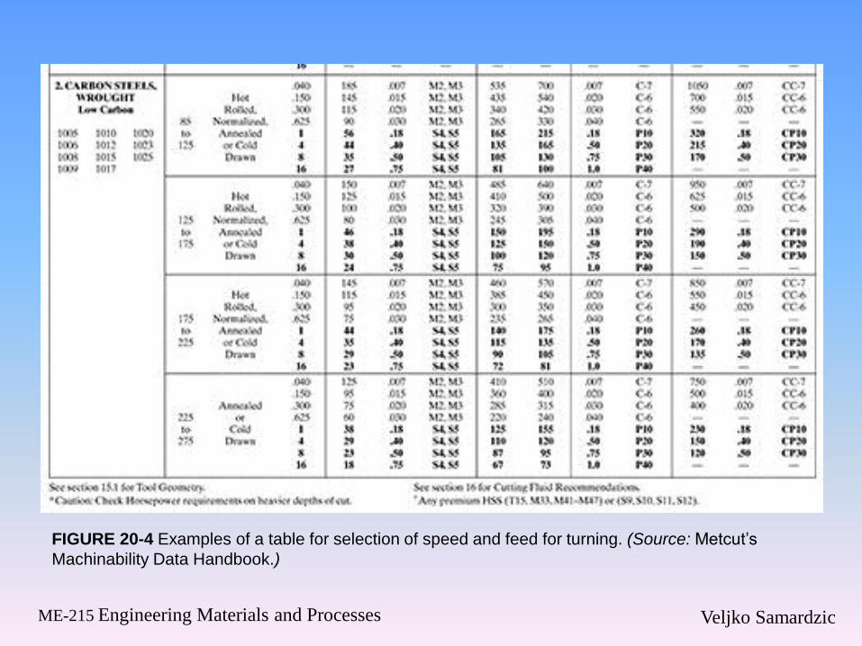
FIGURE 20-4 Examples of a table for selection of speed and feed for turning. (Source: Metcut’s
Machinability Data Handbook.)
Veljko Samardzic ME-215 Engineering Materials and Processes
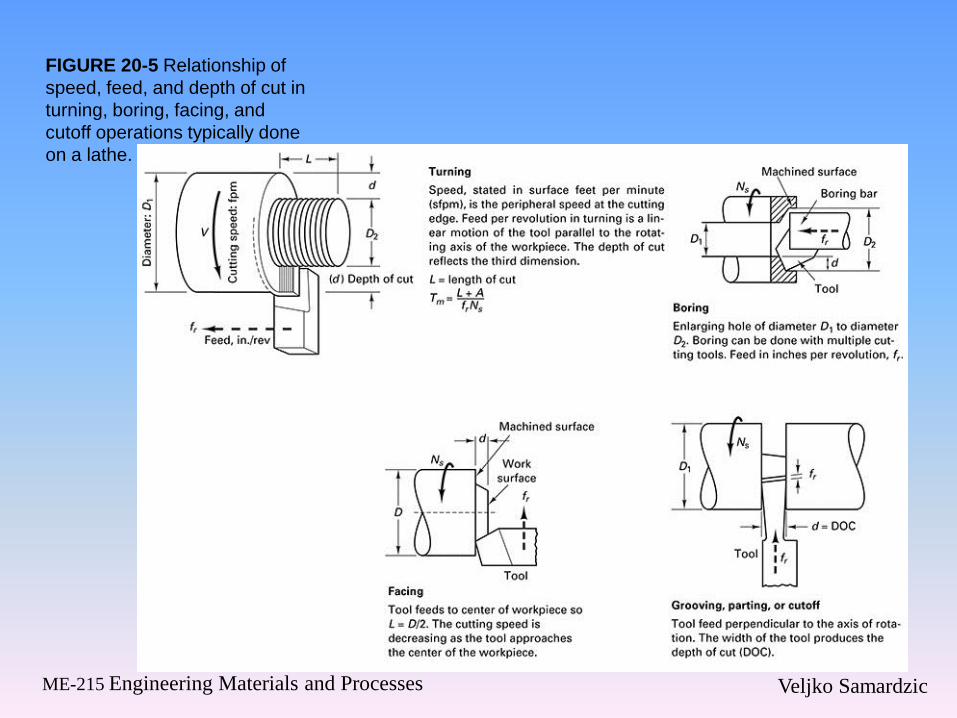
FIGURE 20-5 Relationship of
speed, feed, and depth of cut in
turning, boring, facing, and
cutoff operations typically done
on a lathe.
Veljko Samardzic ME-215 Engineering Materials and Processes

Veljko Samardzic ME-215 Engineering Materials and Processes
FIGURE 20-6 Basics
of milling processes
(slab, face, and end
milling) including
equations for cutting
time and metal
removal rate (MRR).

Veljko Samardzic ME-215 Engineering Materials and Processes
FIGURE 20-7 Basics of the drilling (hole-making)
processes, including equations for cutting time and
metal removal rate (MRR).

Veljko Samardzic ME-215 Engineering Materials and Processes
FIGURE 20-8 Process basics of
broaching. Equations for cutting
time and metal removal rate
(MRR) are developed in
Chapter 26
Veljko Samardzic ME-215 Engineering Materials and Processes
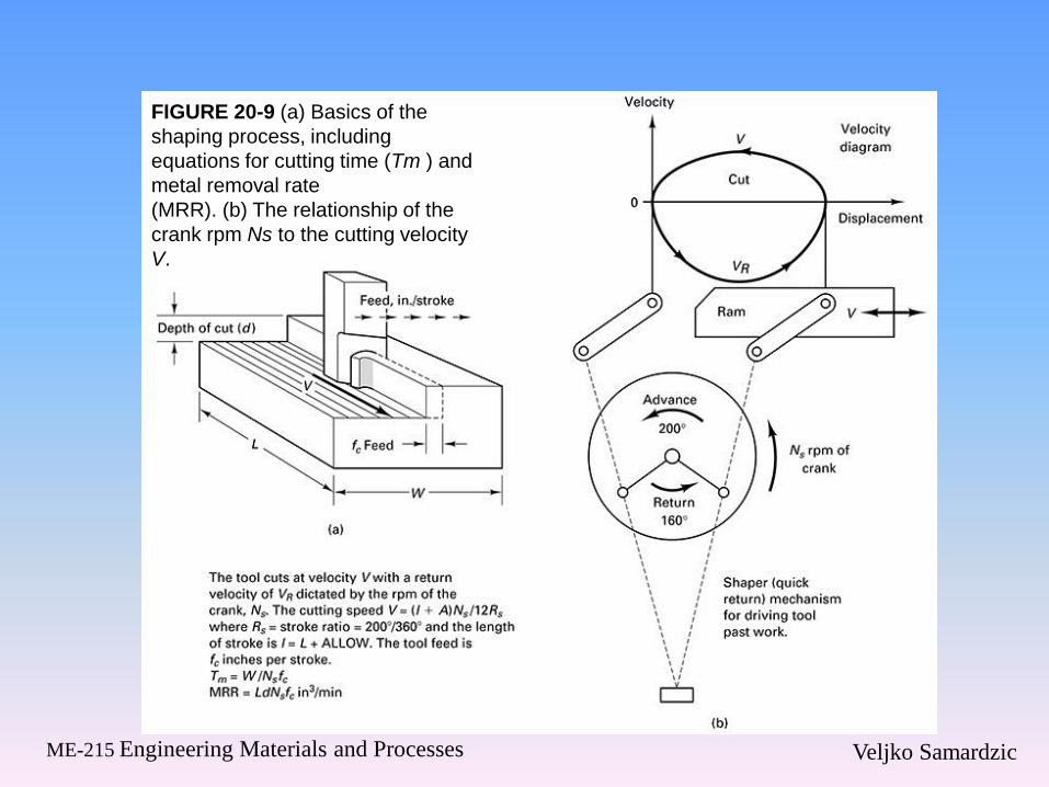
FIGURE 20-9 (a) Basics of the
shaping process, including
equations for cutting time (Tm ) and
metal removal rate
(MRR). (b) The relationship of the
crank rpm Ns to the cutting velocity
V.
Veljko Samardzic ME-215 Engineering Materials and Processes
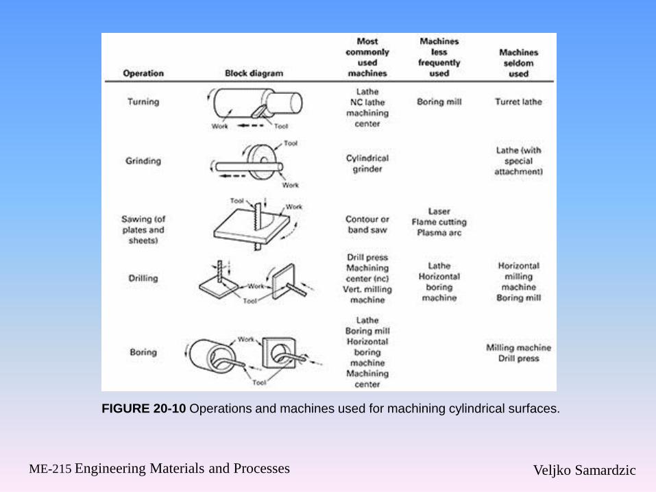
FIGURE 20-10 Operations and machines used for machining cylindrical surfaces.

Veljko Samardzic ME-215 Engineering Materials and Processes
FIGURE 20-10 Operations and machines used for machining cylindrical surfaces.
Veljko Samardzic ME-215 Engineering Materials and Processes
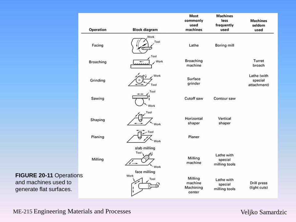
FIGURE 20-11 Operations
and machines used to
generate flat surfaces.

Veljko Samardzic ME-215 Engineering Materials and Processes
20.3 Energy and Power in
Machining
Veljko Samardzic ME-215 Engineering Materials and Processes

Veljko Samardzic ME-215 Engineering Materials and Processes
FIGURE 20-12 Oblique
machining has three measurable
components of forces acting on
the tool. The forces vary with
speed, depth of cut, and feed.
Veljko Samardzic ME-215 Engineering Materials and Processes

Veljko Samardzic ME-215 Engineering Materials and Processes
FIGURE 20-13 Three ways to perform
orthogonal machining. (a) Orthogonal plate
machining on a horizontal milling machine, good
for low-speed cutting. (b) Orthogonal tube turning
on a lathe; high-speed cutting (see Figure 20-16).
(c) Orthogonal disk machining on a lathe;
very high-speed machining with tool feeding (ipr)
in the facing direction

Veljko Samardzic ME-215 Engineering Materials and Processes
20.4 Orthogonal Machining (Two
Forces)

Veljko Samardzic ME-215 Engineering Materials and Processes
FIGURE 20-14 Schematics of
the orthogonal plate machining
setups. (a) End view of table,
quick-stop device (QSD), and
plate being machined for OPM.
(b) Front view of horizontal
milling machine. (c) Orthogonal
plate machining with fixed tool,
moving plate. The feed
mechanism of the mill is used to
produce low cutting speeds. The
feed of the tool is t and the DOC
is w, the width of the plate.

Veljko Samardzic ME-215 Engineering Materials and Processes
FIGURE 20-15 Orthogonal
tube turning (OTT) produces a
two-force cutting operation at
speeds equivalent to those used
in most oblique machining
operations. The slight difference
in cutting speed between the
inside and outside edge of the
chip can be neglected.
Veljko Samardzic ME-215 Engineering Materials and Processes
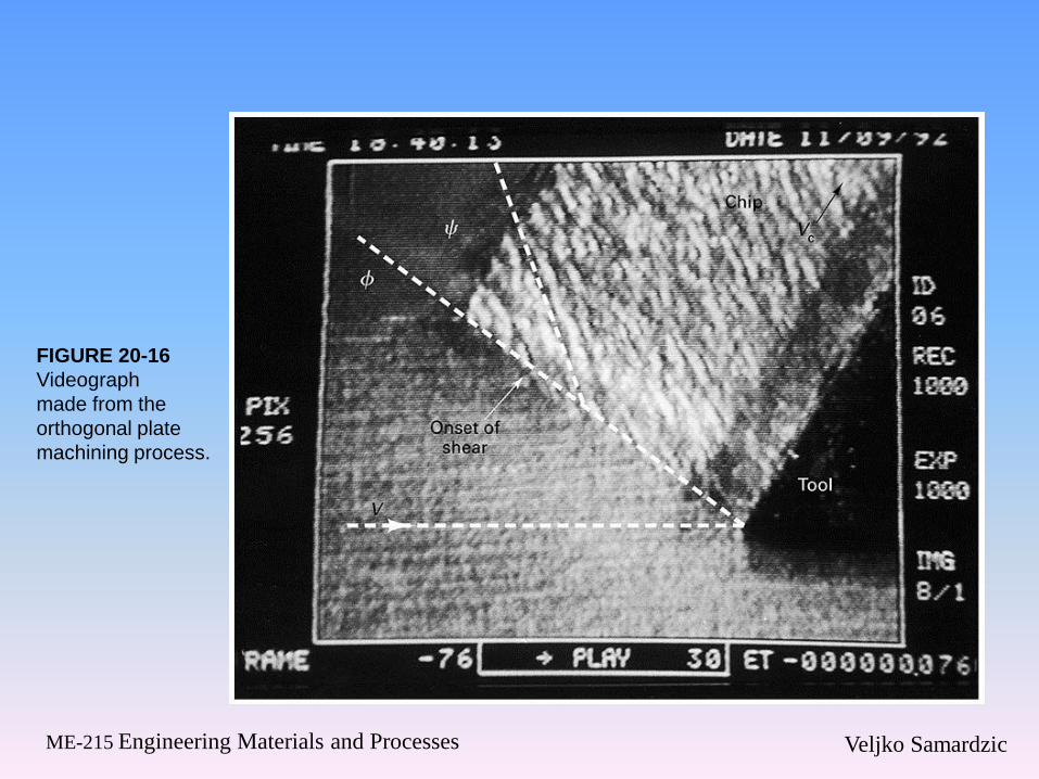
FIGURE 20-16
Videograph
made from the
orthogonal plate
machining process.
Veljko Samardzic ME-215 Engineering Materials and Processes
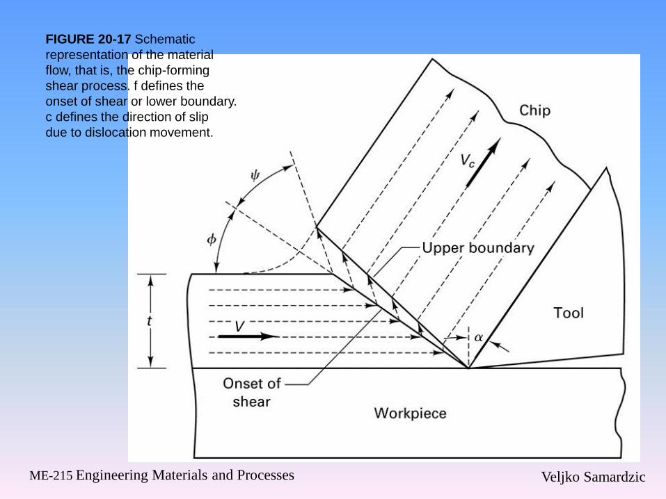
FIGURE 20-17 Schematic
representation of the material
flow, that is, the chip-forming
shear process. f defines the
onset of shear or lower boundary.
c defines the direction of slip
due to dislocation movement.

Veljko Samardzic ME-215 Engineering Materials and Processes
FIGURE 20-18 Three characteristic types of chips.
(Left to right) Discontinuous, continuous, and
continuous with built-up edge. Chip samples produced
by quick-stop technique. (Courtesy of Eugene Merchant
(deceased) at Cincinnati Milacron, Inc., Ohio.)

Veljko Samardzic ME-215 Engineering Materials and Processes
20.5 Merchant’s Model

Veljko Samardzic ME-215 Engineering Materials and Processes
FIGURE 20-19 Velocity
diagram associated with
Merchant’s orthogonal
machining model.
Veljko Samardzic ME-215 Engineering Materials and Processes
20.6 Mechanics of Machining
(Statics)

Veljko Samardzic ME-215 Engineering Materials and Processes
FIGURE 20-20 Free-body diagram of orthogonal chip
formation process, showing equilibrium condition
between resultant forces R and R.

Veljko Samardzic ME-215 Engineering Materials and Processes
FIGURE 20-21 Merchant’s circular force diagram used
to derive equations for Fs , Fr , Ft , and N as functions
of Fc, Fr , f, a, and b.
Veljko Samardzic ME-215 Engineering Materials and Processes
20.7 Shear Strain and Shear Front
Angle

Veljko Samardzic ME-215 Engineering Materials and Processes
FIGURE 20-22 Shear
stress ts variation with
the Brinell hardness
number for a group of
steels and aerospace
alloys. Data of some
selected fcc metals are
also included. (Adapted
with permission from S.
Ramalingham and K. J.
Trigger, Advances in
Machine Tool Design and
Research, 1971,
Pergamon Press.)
Veljko Samardzic ME-215 Engineering Materials and Processes
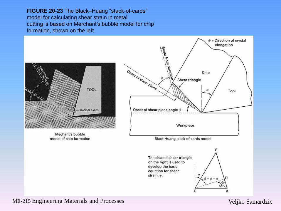
FIGURE 20-23 The Black–Huang “stack-of-cards”
model for calculating shear strain in metal
cutting is based on Merchant’s bubble model for chip
formation, shown on the left.
Veljko Samardzic ME-215 Engineering Materials and Processes
20.8 Mechanics of Machining
(Dynamics)
Veljko Samardzic ME-215 Engineering Materials and Processes
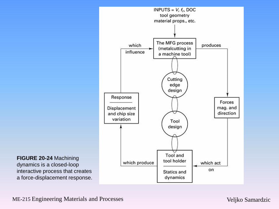
FIGURE 20-24 Machining
dynamics is a closed-loop
interactive process that creates
a force-displacement response.
Veljko Samardzic ME-215 Engineering Materials and Processes
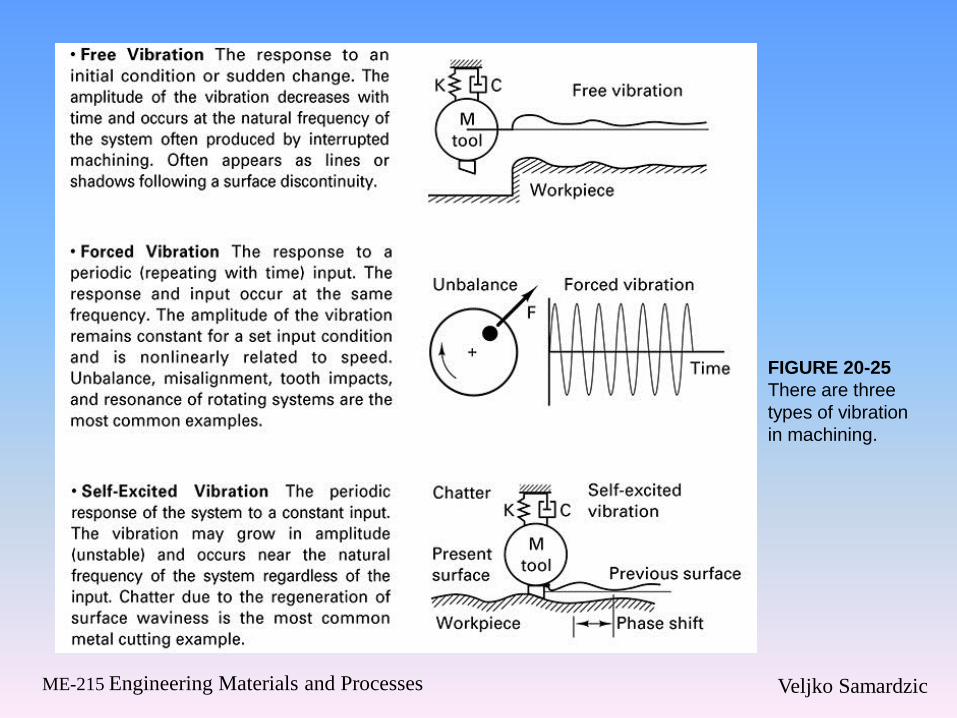
FIGURE 20-25
There are three
types of vibration
in machining.

Veljko Samardzic ME-215 Engineering Materials and Processes
FIGURE 20-26 Some
examples of chatter that are
visible on the surfaces of the
workpiece.

Veljko Samardzic ME-215 Engineering Materials and Processes
FIGURE 20-27 When the
overlapping cuts get out of
phase with each other, a variable
chip thickness is produced,
resulting in a change in Fc on the
tool or workpiece.
Veljko Samardzic ME-215 Engineering Materials and Processes
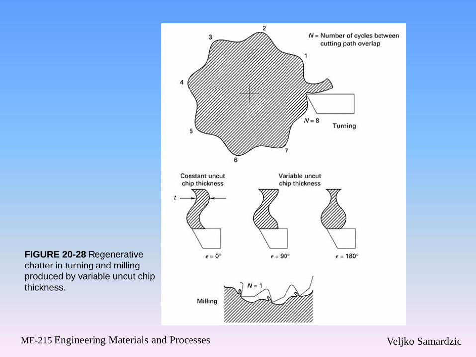
FIGURE 20-28 Regenerative
chatter in turning and milling
produced by variable uncut chip
thickness.

Veljko Samardzic ME-215 Engineering Materials and Processes
FIGURE 20-29 Milling and boring operations can be made more stable by correct selection of insert geometry.
Veljko Samardzic ME-215 Engineering Materials and Processes
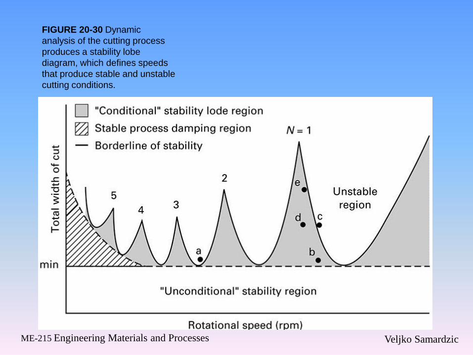
FIGURE 20-30 Dynamic
analysis of the cutting process
produces a stability lobe
diagram, which defines speeds
that produce stable and unstable
cutting conditions.
Veljko Samardzic ME-215 Engineering Materials and Processes
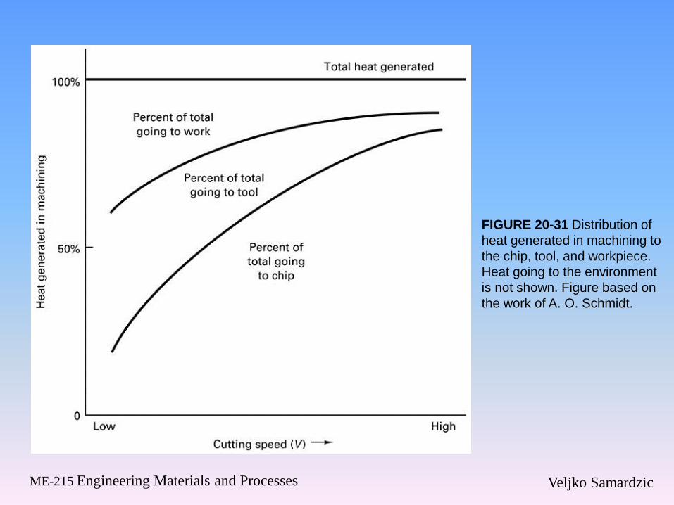
FIGURE 20-31 Distribution of
heat generated in machining to
the chip, tool, and workpiece.
Heat going to the environment
is not shown. Figure based on
the work of A. O. Schmidt.

Veljko Samardzic ME-215 Engineering Materials and Processes
FIGURE 20-32 There are three main sources of heat in metal cutting. (1) Primary shear zone. (2)
Secondary shear zone tool–chip (T–C) interface. (3) Tool flank. The peak temperature occurs at the
center of the interface, in the shaded region.
Veljko Samardzic ME-215 Engineering Materials and Processes
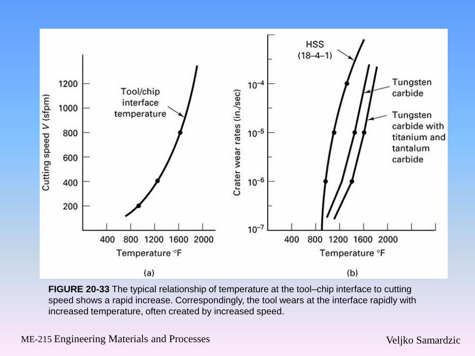
FIGURE 20-33 The typical relationship of temperature at the tool–chip interface to cutting
speed shows a rapid increase. Correspondingly, the tool wears at the interface rapidly with
increased temperature, often created by increased speed.
Veljko Samardzic ME-215 Engineering Materials and Processes
20.9 Summary