Embed Size (px)
Citation preview

FINITE ELEMENTSIMULATION IN ORTHOGONAL
MACHINING OF INCONEL 718 ALLOY
P.DEEPAGANESH. ME CAD/CAM, Shanmuganathan Engineering College, Pudukottai.
ABSTRACT
Knowing the stringent operating conditions to which super alloys are subjected to in automobile,
aerospace and gas turbine industries, their efficient machining and generation of machined surface with
integrity assumes a lot of importance. Considerable attention has been given to the use of ceramic tools for improving productivity in the machining of heat resistant super alloy (HRSA) in recent years.
However, because of their negative influence on the surface integrity, ceramic tools are generally avoided
particularly for finishing applications. The high end manufactures are more or less dependent on carbide
cutting tools for finishing operations. In this present investigation, finite element analysis (FEA) of machining of Inconel 718 Super alloy is carried out using DEFORM 2D. Orthogonal cutting experiments
are carried out on a cylindrical bar of Inconel 718 with a cutting speed 50 m/min, feed rate of 0.1 mm/rev
and nose radius of 0.6, 0.8 & 1.0 mm. The Johnson-Cook (J-C) constitutive equation is implemented in the finite element code to study the behavior of Inconel 718 during the machining process. The FE results
for effective stress, strain, temperature and damage are analyzed. The simulation results showed that the
chip segmentation is not occurred at the low cutting speed Damage distribution is large in the case of 0.6 mm tool nose radius compared with other nose radius values. Residual stress measurements are a
powerful evaluation criterion for selecting the proper cutting tools because of their sensitiveness of
variations in tool parameters.
1. INTRODUCTION
Nickel-based super alloy development of aerospace began in the 1930s. Need for the more
creep resistant material than the available
austenitic stainless steel propelled research to
develop new super alloy. The principal characteristics of nickel as an alloy base are
highly phase stability of Face Centered
Cubic(FCC) nickel matrix and outstanding strength retention up to 0.7Tm (melting point).
These characteristics encourage use of nickel
based super alloys in vast number of applications subjected high temperatures.
Commercially available nickel base super alloys
include inconel, nimonic, rene, udimet, and
pyromet. Inconel 718 is the most frequently used nickel based super alloys; hence this study is
focused on an investigation into the mechanics
of machining inconel 718.
1.1 MACHINING OF NICKEL BASED
SUPERALLOYS Nickel based alloys work-harden
rapidly. Work hardening results in strengthening
of the Material. Plastic deformation during machining
leads to heat generation. High temperature
gradients are localized in narrow bands along shear plane due to poor thermal properties of
inconel 718, leading to weakening the material
in the deformation zone. Water-base fluids are preferred in high speed turning, milling and
grinding because of their greater cooling effect.
For slower operations, such as drilling, boring,
tapping and broaching heavy lubricants and very rich mixtures of chemical solutions are needed.
Tool geometry and machining parameters play
important role in evaluating machining efficiency in machining inconel 718. Single
point cutting tool with positive rake angles (0⁰
for roughing and 8⁰ for finishing) are
International Journal of Mechanical Engineering and Research, ISSN 0973-4562 Vol. 5 No.1 (2015) © Research India Publications; http://www.ripublication.com/ijmer.htm
49
recommended in turning so that metal is cut
instead of ploughed.
2.1 WORKPIECE AND TOOL MATERIAL
INCONEL 718
It is difficult to shape as well as machining Inconel 718 using traditional
techniques dueto rapid work hardening. After
the first machining pass, work hardening tends to plastically deform either the workpiece or the
tool on subsequent passes. For this reason, age-
hardened Inconel such as 718 are machined
using an aggressive but slow cut with a hard tool, minimizing the number of passes required.
Property 21⁰C 540
⁰C 650⁰C 760⁰C 870⁰C
Yield
strength
(MPa)
1185 106
5 1020 740 330
Ultimate
tensile
strength(MPa
)
1435 127
5 1228 950 340
Elastic
modulus
(GPa)
200 171 163 154 139
Specific heat
capacity(J/Kg
K)
430 560 ---------
---
---------
--- 645
Thermal
conductivity(
W/mK)
11.4 19.6 ---------
----
---------
---- 24.9
Coefficient of
thermal
expansion
----------
----- 14.4
---------
-----
---------
-----
---------
-----
Melting range
(⁰C)
1260-
1335
Density
(Kg/m3) 8220
Table 2.1 Physical properties of Inconel 718
Ni Fe Cr Mo Nb Ti Al C Mn Si
52.5 18.5 19 3 5.1 0.9 0.5 0.04 2 0.2
Table 2.2. Chemical composition of Inconel
718 (%wt)
3.MATERIAL MODEL
The johnson-cook model as given in equation
estimates the work Material flow stress as a product of strain, strain rate, and temperature
effects, i.e., work hardening and thermal
softening The Johnson-Cook model has two
principal elements: plasticity and damage
initiation. The plasticity model prescribes the
dependency of plastic flow stress on
equivalent plastic strain , equivalent plastic
strain rate , and temperature: where A, B, C,
and m are constants; n is strain hardening
exponent; 0 is the normalized equivalent
plastic strain rate (typically normalized to a
strain rate of 1.0 s-1
); and ˆm is the homologous
temperature defined as
0
ˆ1 ln 1n mA B C
A
(Mpa)
B
(Mpa) C n m
-
(1/s)
Room
temperature
(c)
Melting
temperature
(c)
450.0 1700.0 0.017 0.65 1.3 0.001 20.0 1297.0
Table. 3.1Johnson-Cook material constants
for Inconel 718
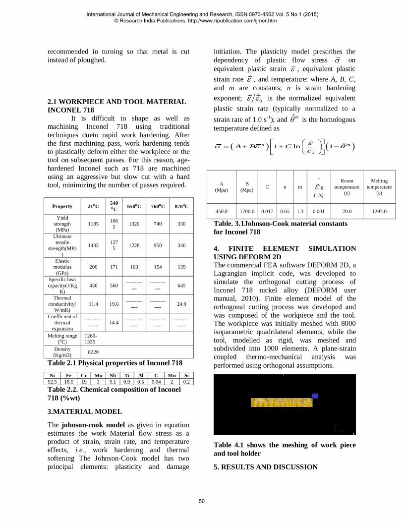
4. FINITE ELEMENT SIMULATION
USING DEFORM 2D The commercial FEA software DEFORM 2D, a
Lagrangian implicit code, was developed to
simulate the orthogonal cutting process of
Inconel 718 nickel alloy (DEFORM user manual, 2010). Finite element model of the
orthogonal cutting process was developed and
was composed of the workpiece and the tool. The workpiece was initially meshed with 8000
isoparametric quadrilateral elements, while the
tool, modelled as rigid, was meshed and subdivided into 1000 elements. A plane-strain
coupled thermo-mechanical analysis was
performed using orthogonal assumptions.
Table 4.1 shows the meshing of work piece
and tool holder
5. RESULTS AND DISCUSSION
International Journal of Mechanical Engineering and Research, ISSN 0973-4562 Vol. 5 No.1 (2015) © Research India Publications; http://www.ripublication.com/ijmer.htm
50

The finite element results for effective
stress, strain, temperature distribution and damage with the input material model for
different tool nose radius are presented in this
chapter. The analysis is presented for cutting
speed of 50 m/min and feed rate of 0.1 mm/rev for all different tool nose radius values (0.6, 0.8
& 1.0 mm).the cutting speed and feed rate at
constant in this study. The FE output was observed at nearly steady state conditions in the
study.
5.1 STRESS ANALYSIS
The von mises stress plot for effective stress distribution for 0.6, 0.8 & 1.0 mm tool
nose radius are shown in figures 5.1 to 5.3. The
negative rake angle causes the greater stress on the work material and the tool at the point of
contact. The stress on the machined surface is
residual in nature while stress value is decreased around the uncut surface and the deformed chip.
Fig 5.1 stress distribution at 0.6mm nose radius
Fig 5.2 stress distribution at 0.8mm nose radius
Fig 5.3 stress distribution at 1.0mm nose radius
5.2 STRAIN DISTRIBUTION
Figures 5.4 to 5.6 show the predicted
effective strain distribution for 0.6, 0.8 & 1.0 mm tool nose radius values. The plastic strain is
higher at the primary zone followed by the
secondary shear zone and least at the free end of
the chip. The chips shows regions of high and low strain across the chip thickness, suggesting a
complex chip formation mode which results in
serration and segments at low cutting speed machining. In other materials this phenomenon
is presented only in high cutting speed
machining. The higher stress near the shear
plane for radius
Fig 5.4 strain distribution at 0.6mm nose radius
International Journal of Mechanical Engineering and Research, ISSN 0973-4562 Vol. 5 No.1 (2015) © Research India Publications; http://www.ripublication.com/ijmer.htm
51

Fig 5.5 strain distribution at 0.8mm nose radius
Fig 5.6 strain distribution at 1.0mm nose radius
1.0mm and 0.8mm should suggest higher
deformations, but only 0.8mm replicates this
proposition. 1.0mm and 0.8mm shows higher deformation at the shear plane tool chip contact
respectively. It can be concluded that the nose
radius 0.8mm with an optimized strain
hardening exponent „n‟ is a good tool for predicting plastic strain path of nickel alloy.
5.3 TEMPERATURE DISTRIBUTION
Figures 5.7 to 5.9 show that the
temperature distribution for the various nose
radius heatTransfers in the machining
process takes place primarily in the shear
zone was the plasticWork is converted into
heat and the chip tool interface where the
frictional heat is generated
Fig 5.7Temperature distribution at 0.6mm
nose radius
Fig 5.8 Temperature distribution at 0.8mm
nose radius
Fig 5.9 Temperature distribution at 1.0mm
nose radius
5.4 DAMAGE DISTRIBUTION
Figure 5.10 and 5.11 show that damage
value distribution in the chip during cutting of Inconel 718. The location of a larger damage
value is correctly corresponding to the above
Discussed stress state in chip segmentation. It
can be seen that high damage value is located at a different region as the nose radius changes.
Figure 5.10 Damage distribution for tool nose
radius of 0.6 mm
International Journal of Mechanical Engineering and Research, ISSN 0973-4562 Vol. 5 No.1 (2015) © Research India Publications; http://www.ripublication.com/ijmer.htm
52

Figure 5.11 Damage distribution for tool nose
radius of 0.8 mm
6. REFERENCES
1. Akhyar, et.al., (2008), “Application
of Taguchi method in the
optimization of turning parameters for surface roughness.” International
journal of science, engineering and
technology- vol 1 no3:2008
2. Childs, et al., “Metal machining
theory and application”. Arnold,
London, 2000.
3. Deshayes, Mabrouki, Lvester, and
Rigal., (2004), “Serrated chip morphology and comparison with
finite element simulations”. ASME
International mechanical Engineering congress and
Exposition, Nov 13-20; 2004.
4. Duan, Dou, Cai, and .LI., (2009),” Finite element simulation and
experiment of chip formation
process during high speed machining of AISI 1045 hardened
steel”. International journal of recent
trends in engineering vol1 no:5 may 2009.
5. Ezugwu, Bonney, Yamane., (1999) “The machinability of nickel based
alloys: a review”. Journal of
material processing technology 86
(1999) 17-44
6. Fang and Wu, “ A comparative
study of cutting forces in high speed machining of Ti-6Al-4V and Inconel
718 with round cutting edge”.
Journal of material processing
technology, 209(2009) 4385-4389.
7. Jiang Hua, Rajiv Shivpuri,(2004),
“Prediction of chip morphology and segmentation during the machining
of Titanium alloy”. Journal of
materials process technology 150(2004) 123-133.
8. Komanduri and Schroeder.,(1986), “On shear instability in machining a
NickelIron base super alloy”,
Transaction of ASME, Journal of
Engineering for Industry 108 (1986) 93-100.
9. Marurich, and Askari., (2000), ”modelling residual stress and work
piece quality in machined surface.
10. Marurich, and Askari (2001),
“simulation and analysis of chip
breakage in turning process” 28
march 2001
11. Obikawa and andUsi (1998). ”computational machining of
Titanium alloy- finite element
modelling and few results”. Journal of manufacturing science and
Engineering, may 1996, volume
118.
12. Ozel, and Ultan (2012) “Prediction
of machining include residual
stresses in turning of Titanium and Nickel based alloy with experiments
and finite element simulations”.
CIRP Annals- manufacturing technology 61(2012)547-550.
13. Pawade, Harshad A Sonawane, Suhas . s. Joshi (2009),” an
International Journal of Mechanical Engineering and Research, ISSN 0973-4562 Vol. 5 No.1 (2015) © Research India Publications; http://www.ripublication.com/ijmer.htm
53

analytical model to predict specific
shear energy in high speed turning of Inconel 718”. International
journal of machine tools &
manufactures. 42(2009)979-999.
International Journal of Mechanical Engineering and Research, ISSN 0973-4562 Vol. 5 No.1 (2015) © Research India Publications; http://www.ripublication.com/ijmer.htm
54