Embed Size (px)
Citation preview
1
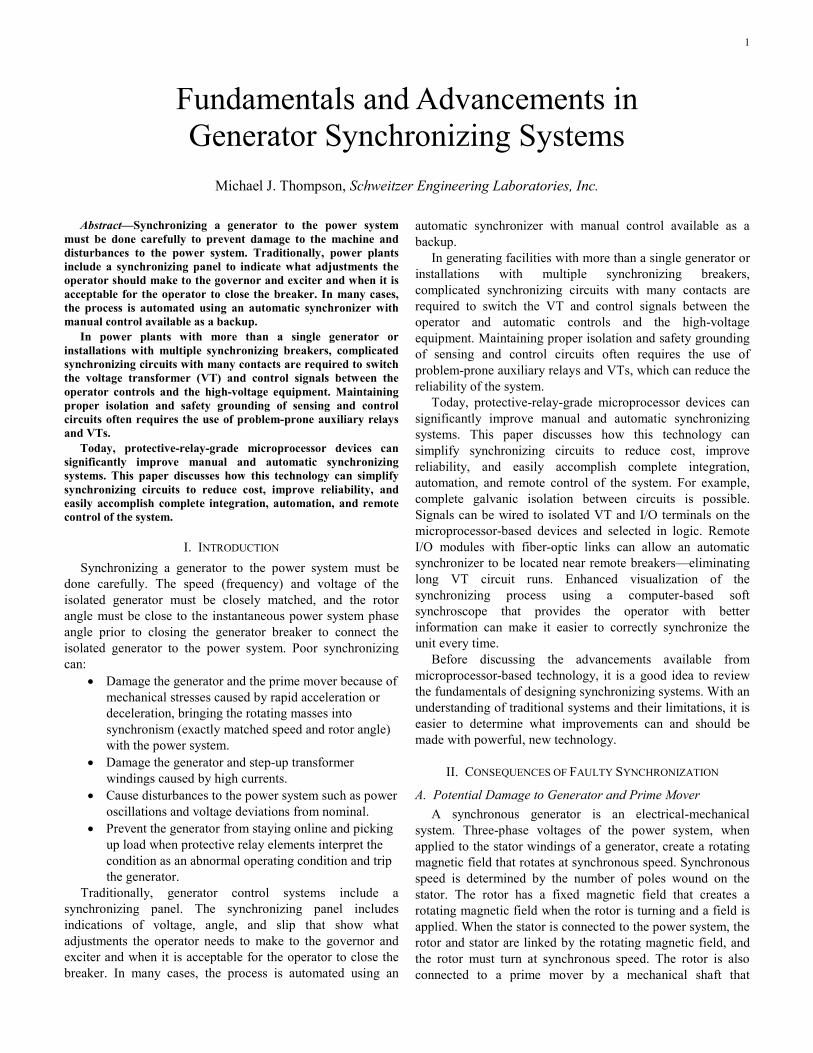
Fundamentals and Advancements in Generator Synchronizing Systems
Michael J. Thompson, Schweitzer Engineering Laboratories, Inc.
Abstract—Synchronizing a generator to the power system must be done carefully to prevent damage to the machine and disturbances to the power system. Traditionally, power plants include a synchronizing panel to indicate what adjustments the operator should make to the governor and exciter and when it is acceptable for the operator to close the breaker. In many cases, the process is automated using an automatic synchronizer with manual control available as a backup.
In power plants with more than a single generator or installations with multiple synchronizing breakers, complicated synchronizing circuits with many contacts are required to switch the voltage transformer (VT) and control signals between the operator controls and the high-voltage equipment. Maintaining proper isolation and safety grounding of sensing and control circuits often requires the use of problem-prone auxiliary relays and VTs.
Today, protective-relay-grade microprocessor devices can significantly improve manual and automatic synchronizing systems. This paper discusses how this technology can simplify synchronizing circuits to reduce cost, improve reliability, and easily accomplish complete integration, automation, and remote control of the system.
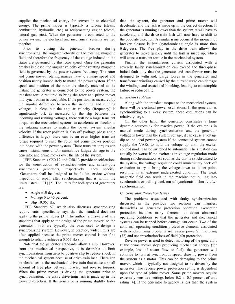
I. INTRODUCTION Synchronizing a generator to the power system must be
done carefully. The speed (frequency) and voltage of the isolated generator must be closely matched, and the rotor angle must be close to the instantaneous power system phase angle prior to closing the generator breaker to connect the isolated generator to the power system. Poor synchronizing can:
• Damage the generator and the prime mover because of mechanical stresses caused by rapid acceleration or deceleration, bringing the rotating masses into synchronism (exactly matched speed and rotor angle) with the power system.
• Damage the generator and step-up transformer windings caused by high currents.
• Cause disturbances to the power system such as power oscillations and voltage deviations from nominal.
• Prevent the generator from staying online and picking up load when protective relay elements interpret the condition as an abnormal operating condition and trip the generator.
Traditionally, generator control systems include a synchronizing panel. The synchronizing panel includes indications of voltage, angle, and slip that show what adjustments the operator needs to make to the governor and exciter and when it is acceptable for the operator to close the breaker. In many cases, the process is automated using an
automatic synchronizer with manual control available as a backup.
In generating facilities with more than a single generator or installations with multiple synchronizing breakers, complicated synchronizing circuits with many contacts are required to switch the VT and control signals between the operator and automatic controls and the high-voltage equipment. Maintaining proper isolation and safety grounding of sensing and control circuits often requires the use of problem-prone auxiliary relays and VTs, which can reduce the reliability of the system.
Today, protective-relay-grade microprocessor devices can significantly improve manual and automatic synchronizing systems. This paper discusses how this technology can simplify synchronizing circuits to reduce cost, improve reliability, and easily accomplish complete integration, automation, and remote control of the system. For example, complete galvanic isolation between circuits is possible. Signals can be wired to isolated VT and I/O terminals on the microprocessor-based devices and selected in logic. Remote I/O modules with fiber-optic links can allow an automatic synchronizer to be located near remote breakers—eliminating long VT circuit runs. Enhanced visualization of the synchronizing process using a computer-based soft synchroscope that provides the operator with better information can make it easier to correctly synchronize the unit every time.
Before discussing the advancements available from microprocessor-based technology, it is a good idea to review the fundamentals of designing synchronizing systems. With an understanding of traditional systems and their limitations, it is easier to determine what improvements can and should be made with powerful, new technology.
II. CONSEQUENCES OF FAULTY SYNCHRONIZATION
A. Potential Damage to Generator and Prime Mover A synchronous generator is an electrical-mechanical
system. Three-phase voltages of the power system, when applied to the stator windings of a generator, create a rotating magnetic field that rotates at synchronous speed. Synchronous speed is determined by the number of poles wound on the stator. The rotor has a fixed magnetic field that creates a rotating magnetic field when the rotor is turning and a field is applied. When the stator is connected to the power system, the rotor and stator are linked by the rotating magnetic field, and the rotor must turn at synchronous speed. The rotor is also connected to a prime mover by a mechanical shaft that
2
supplies the mechanical energy for conversion to electrical energy. The prime mover is typically a turbine (steam, combustion, hydraulic, etc.) or reciprocating engine (diesel, natural gas, etc.). When the generator is connected to the power system, the electrical and mechanical systems are tied together.
Prior to closing the generator breaker during synchronizing, the angular velocity of the rotating magnetic field and therefore the frequency of the voltage induced in the stator are governed by the rotor speed. Once the generator breaker is closed, the angular velocity of the rotating magnetic field is governed by the power system frequency. The rotor and prime mover rotating masses have to change speed and position nearly immediately to match the power system. If the speed and position of the rotor are closely matched at the instant the generator is connected to the power system, the transient torque required to bring the rotor and prime mover into synchronism is acceptable. If the position, as measured by the angular difference between the incoming and running voltages, is close but the angular velocity (frequency) is significantly off, as measured by the slip between the incoming and running voltages, there will be a large transient torque on the mechanical systems to accelerate or decelerate the rotating masses to match the power system angular velocity. If the rotor position is also off (voltage phase angle difference is large), there can be an even higher transient torque required to snap the rotor and prime mover position into phase with the power system. These transient torques can cause instantaneous and/or cumulative fatigue damage to the generator and prime mover over the life of the system.
IEEE Standards C50.12 and C50.13 provide specifications for the construction of cylindrical-rotor and salient-pole synchronous generators, respectively. They specify, “Generators shall be designed to be fit for service without inspection or repair after synchronizing that is within the limits listed…” [1] [2]. The limits for both types of generators are:
• Angle ±10 degrees. • Voltage 0 to +5 percent. • Slip ±0.067 Hz.
IEEE Standard 67, which also discusses synchronizing requirements, specifically says that the standard does not apply to the prime mover [3]. The author is unaware of any standards that apply to the design of the prime mover, so the generator limits are typically the ones used to design a synchronizing system. However, in practice, wider limits are often applied because the prime mover control is not fine enough to reliably achieve a 0.067 Hz slip.
Note that the generator standards allow ± slip. However, from the mechanical perspective, it is desirable to limit synchronization from zero to positive slip to reduce shock in the mechanical system because of drive-train lash. There can be clearances in the mechanical drive train that cause a small amount of free play between forward and reverse torques. When the prime mover is driving the generator prior to synchronization, the entire drive-train lash is made up in the forward direction. If the generator is running slightly faster
than the system, the generator and prime mover will decelerate, and the lash is made up in the correct direction. If the generator is running slower than the system, it will have to accelerate, and the drive-train lash will now have to shift to the opposite direction. A similar issue occurs if the moment of breaker closure is late (synchronizing angle is more than 0 degrees). The free play in the drive train allows the generator to move quickly until the lash is made up, which will cause a transient torque in the mechanical system.
Finally, the instantaneous current associated with a severely faulty synchronization can exceed the three-phase bolted fault duty that the generator and transformer must be designed to withstand. Large forces in the generator and transformer windings caused by the current surge can damage the windings and associated blocking, leading to catastrophic failure or reduced life.
B. System Problems Along with the transient torques to the mechanical system,
there will be electrical power oscillations. If the generator is synchronizing to a weak system, these oscillations can be relatively large.
On the other hand, the generator constitutes a large dynamic source/sink for reactive power. If the exciter is in manual mode during synchronization and the generator voltage is lower than the system voltage, it can cause a voltage dip to the local power system if the connected system cannot supply the VARs to hold the voltage up until the exciter control mode can be switched to automatic. The situation can actually be worse if the exciter is in voltage regulation mode during synchronization. As soon as the unit is synchronized to the system, the voltage regulator could immediately back off excitation to try to bring the voltage down to its set point, resulting in an extreme underexcited condition. The weak magnetic field can result in the machine not pulling into synchronism or pulling back out of synchronism shortly after synchronization.
C. Generator Protection Issues The problems associated with faulty synchronization
discussed in the previous two sections can manifest themselves as generator protection operation. Generator protection includes many elements to detect abnormal operating conditions so that the generator and mechanical systems can be tripped before damage can occur. Two of the abnormal operating condition protective elements associated with synchronizing problems are reverse power/antimotoring (32) and underexcitation/loss-of-field (40) protection.
Reverse power is used to detect motoring of the generator. If the prime mover stops producing mechanical energy (for example, loss of steam flow or fuel), the generator will continue to turn at synchronous speed, drawing power from the system as a motor. This can be damaging to the prime mover, which is typically not designed to be driven by the generator. The reverse power protection setting is dependent upon the type of prime mover. Some prime movers require extremely sensitive settings below 0.2 to 0.5 percent of unit rating [4]. If the generator frequency is less than the system
3
frequency, the initial power flow direction is into the generator to accelerate it to synchronous speed, which can cause the unit to immediately trip back out on reverse power.
Underexcitation protection safeguards a generator from going out of step when the field is too weak to keep it in synchronism with the power system. Round-rotor generators have an end-iron heating limit in the underexcited operating region that will damage the generator if the condition persists. Underexcitation is generally detected by impedance relays that detect the apparent impedance when the generator is sinking VARs. If the generator voltage is lower than the system voltage at the point of initial synchronization, a very sensitive loss-of-field relay may cause the unit to immediately trip back out.
Electrical engineers are often quite familiar with these modes of protection operation during synchronization, but it is important to recognize that these problems, while certainly a nuisance, are a symptom of faulty synchronization and not the real issue.
III. SYNCHRONIZING SYSTEM COMPONENTS The synchronizing system must perform the following
functions: • Control the governor to match speed. • Control the exciter to match voltage. • Close the breaker as close to a zero-degree angle
difference as possible. These functions can be provided by the operator using
manual means, automated control systems, or some combination of both. Permissive devices are often included to monitor the process.
A. Manual Synchronizing Systems Generators have traditionally been synchronized by manual
means. The operator manually adjusts the prime mover speed or the frequency control set point of the governor to match the generator frequency to the system frequency. Similarly, the operator manually adjusts the excitation level or voltage regulator set point of the exciter to match the generator voltage to the system voltage.
The operator then initiates closing the breaker when the phase angle between the generator voltage and the system voltage is near 0 degrees. A good operator will judge how fast the phase angle difference is coming together and energize the breaker close coil in advance to account for the closing mechanism delay of the generator breaker so that the main contacts make as close to a zero-degree angle difference as possible.
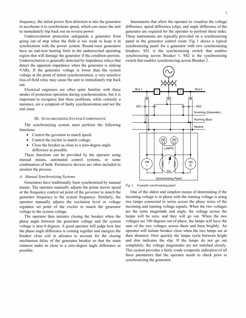
Instruments that allow the operator to visualize the voltage difference, speed difference (slip), and angle difference of the generator are required for the operator to perform these tasks. These instruments are typically provided on a synchronizing panel in the generator control room. Fig. 1 shows a typical synchronizing panel for a generator with two synchronizing breakers. SS1 is the synchronizing switch that enables synchronizing across Breaker 1. SS2 is the synchronizing switch that enables synchronizing across Breaker 2.
Incoming (Generator)
Running (Bus)
Neutral
SS
VMR
VMI
Synchronizing Panel
LAMPS
1 2
SS2SS1
Bus 1 Bus 2
Fig. 1. Example synchronizing panel
One of the oldest and simplest means of determining if the incoming voltage is in phase with the running voltage is using two lamps connected in series across the phase wires of the incoming and running voltage signals. When the two voltages are the same magnitude and angle, the voltage across the lamps will be zero, and they will go out. When the two voltages are 180 degrees out of phase, the lamps will have the sum of the two voltages across them and burn brightly. An operator will initiate breaker close when the two lamps are at their dimmest. How quickly the lamps cycle between bright and dim indicates the slip. If the lamps do not go out completely, the voltage magnitudes are not matched closely. This system provides a fairly crude composite indication of all three parameters that the operator needs to check prior to synchronizing the generator.
4
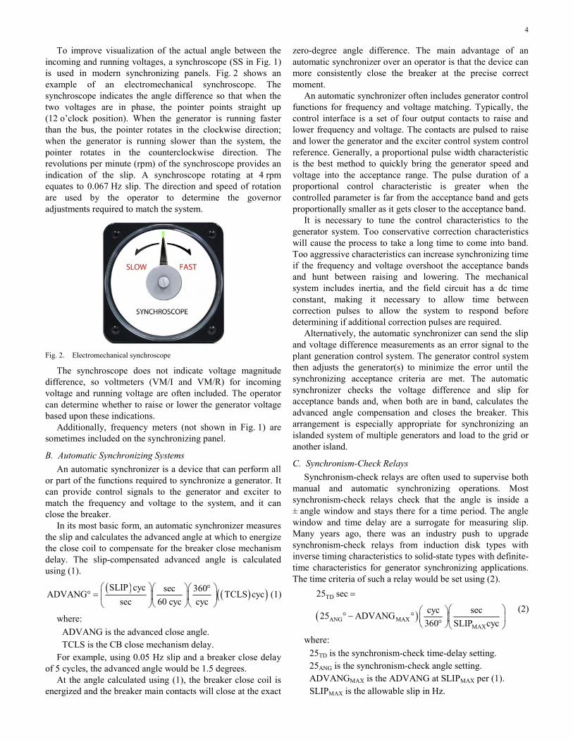
To improve visualization of the actual angle between the incoming and running voltages, a synchroscope (SS in Fig. 1) is used in modern synchronizing panels. Fig. 2 shows an example of an electromechanical synchroscope. The synchroscope indicates the angle difference so that when the two voltages are in phase, the pointer points straight up (12 o’clock position). When the generator is running faster than the bus, the pointer rotates in the clockwise direction; when the generator is running slower than the system, the pointer rotates in the counterclockwise direction. The revolutions per minute (rpm) of the synchroscope provides an indication of the slip. A synchroscope rotating at 4 rpm equates to 0.067 Hz slip. The direction and speed of rotation are used by the operator to determine the governor adjustments required to match the system.
Fig. 2. Electromechanical synchroscope
The synchroscope does not indicate voltage magnitude difference, so voltmeters (VM/I and VM/R) for incoming voltage and running voltage are often included. The operator can determine whether to raise or lower the generator voltage based upon these indications.
Additionally, frequency meters (not shown in Fig. 1) are sometimes included on the synchronizing panel.
B. Automatic Synchronizing Systems An automatic synchronizer is a device that can perform all
or part of the functions required to synchronize a generator. It can provide control signals to the generator and exciter to match the frequency and voltage to the system, and it can close the breaker.
In its most basic form, an automatic synchronizer measures the slip and calculates the advanced angle at which to energize the close coil to compensate for the breaker close mechanism delay. The slip-compensated advanced angle is calculated using (1).
( ) ( )( )SLIP cyc sec 360ADVANG TCLS cycsec 60 cyc cyc
⎛ ⎞⎛ ⎞⎛ ⎞°° = ⎜ ⎟⎜ ⎟⎜ ⎟
⎝ ⎠⎝ ⎠⎝ ⎠ (1)
where: ADVANG is the advanced close angle. TCLS is the CB close mechanism delay.
For example, using 0.05 Hz slip and a breaker close delay of 5 cycles, the advanced angle would be 1.5 degrees.
At the angle calculated using (1), the breaker close coil is energized and the breaker main contacts will close at the exact
zero-degree angle difference. The main advantage of an automatic synchronizer over an operator is that the device can more consistently close the breaker at the precise correct moment.
An automatic synchronizer often includes generator control functions for frequency and voltage matching. Typically, the control interface is a set of four output contacts to raise and lower frequency and voltage. The contacts are pulsed to raise and lower the generator and the exciter control system control reference. Generally, a proportional pulse width characteristic is the best method to quickly bring the generator speed and voltage into the acceptance range. The pulse duration of a proportional control characteristic is greater when the controlled parameter is far from the acceptance band and gets proportionally smaller as it gets closer to the acceptance band.
It is necessary to tune the control characteristics to the generator system. Too conservative correction characteristics will cause the process to take a long time to come into band. Too aggressive characteristics can increase synchronizing time if the frequency and voltage overshoot the acceptance bands and hunt between raising and lowering. The mechanical system includes inertia, and the field circuit has a dc time constant, making it necessary to allow time between correction pulses to allow the system to respond before determining if additional correction pulses are required.
Alternatively, the automatic synchronizer can send the slip and voltage difference measurements as an error signal to the plant generation control system. The generator control system then adjusts the generator(s) to minimize the error until the synchronizing acceptance criteria are met. The automatic synchronizer checks the voltage difference and slip for acceptance bands and, when both are in band, calculates the advanced angle compensation and closes the breaker. This arrangement is especially appropriate for synchronizing an islanded system of multiple generators and load to the grid or another island.
C. Synchronism-Check Relays Synchronism-check relays are often used to supervise both
manual and automatic synchronizing operations. Most synchronism-check relays check that the angle is inside a ± angle window and stays there for a time period. The angle window and time delay are a surrogate for measuring slip. Many years ago, there was an industry push to upgrade synchronism-check relays from induction disk types with inverse timing characteristics to solid-state types with definite-time characteristics for generator synchronizing applications. The time criteria of such a relay would be set using (2).
( )
TD
ANG MAXMAX
25 sec
cyc sec25 ADVANG360 SLIP cyc
=
⎛ ⎞⎛ ⎞° − ° ⎜ ⎟⎜ ⎟°⎝ ⎠⎝ ⎠
(2)
where: 25TD is the synchronism-check time-delay setting. 25ANG is the synchronism-check angle setting. ADVANGMAX is the ADVANG at SLIPMAX per (1). SLIPMAX is the allowable slip in Hz.
5
For such a synchronism-check relay, the time-delay setting must accommodate the advanced angle. So, for the previous example using 0.05 Hz (18 degrees/second) SLIPMAX and an angle setting of 10 degrees, the ADVANGMAX would be 1.5 degrees. The setting 25TD would be less than 0.47 seconds to allow the synchronism-check relay to close its contacts before 1.5 degrees in advance of 0 degrees at SLIPMAX. If the actual slip is less than SLIPMAX, the synchronism-check relay would have closed its permissive contact well in advance of the close command from the operator or the automatic synchronizer.
The problem with this type of synchronism-check relay is that it can cause a late close, up to its angle setting past 0 degrees (in this case, 10 degrees). For example, if the synchronism-check delay is set to 0.47 seconds and the operator has misjudged and initiated the close with slip at 0.10 Hz (36 degrees/second), the close coil would be energized at 6.9 degrees past 0 degrees (because the operator’s hand is still on the control switch). The main contacts would make at 9.9 degrees past 0 degrees because the generator would advance 3 degrees during the 5-cycle mechanism delay at 0.10 Hz. For this reason, it is recommended to set the delay to less than the maximum value calculated using (2).
In the previous late-close scenario, the synchronism-check contact would then drop out at 10 degrees past 0 degrees. The synchronism-check contact would then be in danger of damage when it tries to interrupt the closing circuit current as the contact opens. Often, under these conditions, the contact will weld closed and the synchronism-check function will be inadvertently disabled (permissive contact closed all of the time).
Microprocessor-based synchronism-check elements measure slip directly, so it is not necessary to include a time delay. If the slip and voltage difference are within acceptance criteria, the synchronism-check output asserts as soon as the angle difference comes into the acceptance range. The synchronism-check element will not cause a late close with this type of relay.
More advanced microprocessor-based synchronism-check elements are capable of calculating the slip-compensated advanced angle and adjusting their characteristics to assert permissive trip at the advanced angle instead of the edge of the angle window. For example, with an angle setting of ±30 degrees, the element asserts if the system angle across the breaker is between –30 degrees and +30 degrees. But, when slip is detected, it will assert its contact at 0 degrees minus the advanced angle. So, for the example previously discussed with an advanced angle of 1.5 degrees at 0.05 Hz slip, the synchronism-check element would assert at –1.5 degrees and deassert at 28.5 degrees.
One take away from this discussion is that operators need to understand that a simple synchronism-check relay should not be relied upon to ensure a smooth synchronization. Its main purpose is to prevent a faulty synchronization with a generator significantly out of phase. A microprocessor-based synchronism-check element with a slip-compensated
advanced angle function can be used to initiate closing similar to the feature in an automatic synchronizer.
D. Voltage Relays In addition to synchronism-check relays, voltage relays are
sometimes included to supervise the close command. Voltage checks may include:
• Generator voltage magnitude within acceptance criteria.
• Bus voltage magnitude within acceptance criteria. • Voltage difference within acceptance criteria,
including: − Vector sum voltage difference (electromechanical
or static relays). − Voltage magnitude difference (microprocessor-
based relays). • Live generator/dead bus.
The vector sum voltage difference relay would be connected in parallel with the lamps in Fig. 1. This type of relay only provides a true indication of the voltage magnitude difference at the instant of passing through 0 degrees. The microprocessor-based synchronism-check element measures the voltage magnitude difference directly, so it is preferable for generator applications.
All of these voltage supervision functions are typically included in a microprocessor-based synchronism-check element.
E. Dead-Bus Close Permissive Voltage relays can be used to supervise live-
generator/dead-bus close for black start applications. It is recommended to include an operator-controlled permissive in the dead-bus close logic to prevent a faulty synchronization caused by a blown bus VT fuse. In some cases, the voltage relay is omitted, and the dead-bus close is accomplished by simply wiring the operator-controlled dead-bus permissive contact to bypass the synchronism-check supervisory contact.
IV. SYSTEM DESIGN Synchronizing systems for major generators must be
designed for high reliability. It is important that the system provides accurate and safe synchronizing every time. There should be no single points of failure that prevent placing a generator into service. There should be no common-mode failure mechanisms between control functions and supervisory permissive functions that allow a faulty synchronization.
A. Automatic Versus Manual Systems In base load applications where the generator is only
synchronized to the system a few times a month or year, a manual synchronizing system is often the only system installed. Peaking units that are synchronized several times a week usually include an automatic synchronizing system [5]. Mechanical fatigue damage from small torsional disturbances caused by less-than-perfect synchronization is cumulative over time and can lead to early failure even if a faulty synchronization event never occurs. The improved
6
consistency provided by an automatic synchronizer can limit the opportunity for this cumulative damage over the course of many synchronizations.
There is a dichotomy that needs to be recognized in using frequency of synchronization to determine if an automatic system is required. When manual synchronization only happens rarely, operator practice is reduced versus if synchronization occurs on a regular basis. So the consistency of the operator responses may be quite good if the generator needs to be synchronized often. Some organizations use simulators to maintain operator proficiency.
In applications where operator proficiency is not adequate or in unmanned facilities, the choice may be made to rely completely on automatic synchronizing systems.
B. Multiple Levels of Supervision A generator synchronizing system can use any combination
of the previously described components. Because of the severe consequences of faulty synchronizing, in many cases, the systems often include multiple levels of supervision. For example, a two-level system includes:
• Manual or automatic adjustment of generator speed and voltage.
• Slip-compensated advance angle close from an: − Operator manual control switch. − Automatic synchronizer.
• Multifunction synchronism-check relay supervision. Requiring two contacts in series to energize the close coil
can prevent a faulty synchronization, for example, if one of the contacts is welded closed.
Systems can also be designed for three-level supervision. On such a system, energizing the breaker close coil requires the synchronism-check relay to assert, the automatic synchronizer to initiate close, and an operator observing the indications on the synchronizing panel to close a manual control switch. Such a system often includes logic to lock out the close process if the operator initiates a permissive contact when outside the acceptance criteria. The purpose of this logic is to prevent operators from taking themselves out of the close process by holding the control switch closed and letting the other contacts initiate closing the breaker [6].
C. Redundancy Generally, there is always a manual synchronizing system:
the main components being the visualization system (synchronizing panel), the manual speed and voltage controls, and the breaker close control. Even in installations that use an automatic synchronizing system exclusively, providing the synchronizing panel for monitoring the automatic system is desirable. Further, to eliminate a single point of failure of the automatic system, the manual system can provide backup by allowing the generator to be brought online manually if the automatic system is out of service.
If automatic synchronizing is the only method allowed to bring the generator online and it is not acceptable for the generator to be unavailable if the automatic system is out of
service, the system design should include primary and standby automatic systems.
D. Design for Fault Tolerance The system design should be evaluated for common-mode
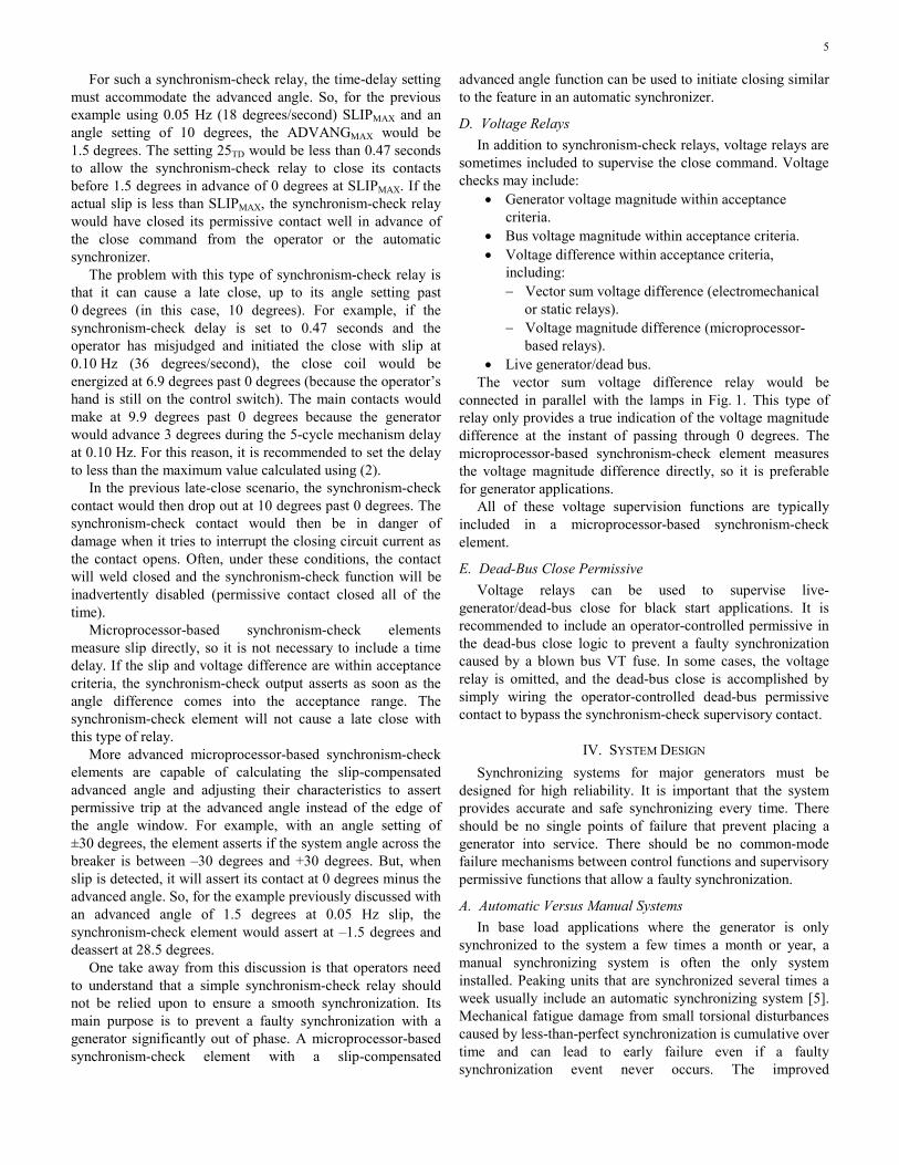
failure problems. These can involve problems in the voltage circuits or in the breaker close control circuits. The two-synchronizing-breaker application illustrated in Fig. 3 is used as an example. In the figure, SS represents the complete synchronizing panel used by the operator to monitor the synchronizing parameters and determine when to close the breaker. Device 25 is a multifunction synchronism-check relay. Device 25A is an automatic synchronizer. Generator 2 synchronizing switch circuits are similar to Generator 1 synchronizing switch circuits to connect the proper voltages to the synchronizing panel. The synchronizing switches have removable handles. Only one handle is provided to the operator so that only one of the four synchronizing switches can be in the ON position at a time. Note that instrument transformer circuit safety grounds are not shown in Fig. 3 but should be present. See the “Isolation” portion of Section IV, Subsection E of this paper for more discussion on VT circuit grounding.
To G
2 S
S
Circ
uits
Fig. 3. Synchronizing circuit example
1) Common-Mode VT Sensing Failure If the system is a two-level verification system with both
automatic and manual synchronizing systems, a breaker close action will occur if the synchronism-check relay asserts and either the operator or the 25A element initiates a close. This design will prevent an out-of-synchronism close caused by a single failure of the synchronism-check relay, the operator, or the automatic synchronizer.
7
However, in the illustrated design in Fig. 3, all three systems are monitoring the same incoming and running voltage signals. This represents a common-mode failure. If there is a problem that results in the application of incorrect voltage signals to the incoming or running circuits, a faulty synchronization could occur.
One possible scenario is if the incoming voltage is inadvertently from a source that is in synchronism with the running voltage instead of the generator. Because zero slip and zero angle difference are within the synchronism check and acceptance criteria of the automatic synchronizer, a faulty close could occur. An advanced automatic synchronizer, discussed in Section V, will not initiate a close under these conditions because it requires the angle to be advancing on 0 degrees prior to initiating a close output.
Another scenario is the case where live-generator/dead-bus close is allowed. If the bus VT fuse is blown and the running voltage is dead, a faulty close could occur. As mentioned previously, dead-bus close is usually designed to require an operator to enable this close mode.
In these failure scenarios, an operator would more likely determine that the signals are not correct by observing that the synchroscope behavior is not as expected or does not match the speed indications coming from the turbine control system. So a system that requires three-level validation and involves a human operator would be more fault tolerant of this failure mode. This example illustrates an important distinction between manual and automatic systems—human beings are better at spotting anomalous information, while automated systems are more precise and consistent.
2) Control Circuit Failures Another consideration is that the breaker close control
circuits may have common components. In Fig. 3, 25A can be used to close each of the four generator synchronizing breakers (two for G1 and two for G2). The single close contact is routed to the proper circuit breaker through the synchronizing switch circuits. Isolation of the control circuits typically requires auxiliary relays. Complex circuits with lots of problem-prone switch and auxiliary relay contacts and coils can contain hidden failures or sneak circuits that can cause inadvertent closing of a second breaker when the selected breaker is being controlled.
3) One Solution to Common-Mode Failure A design improvement to eliminate these common-mode
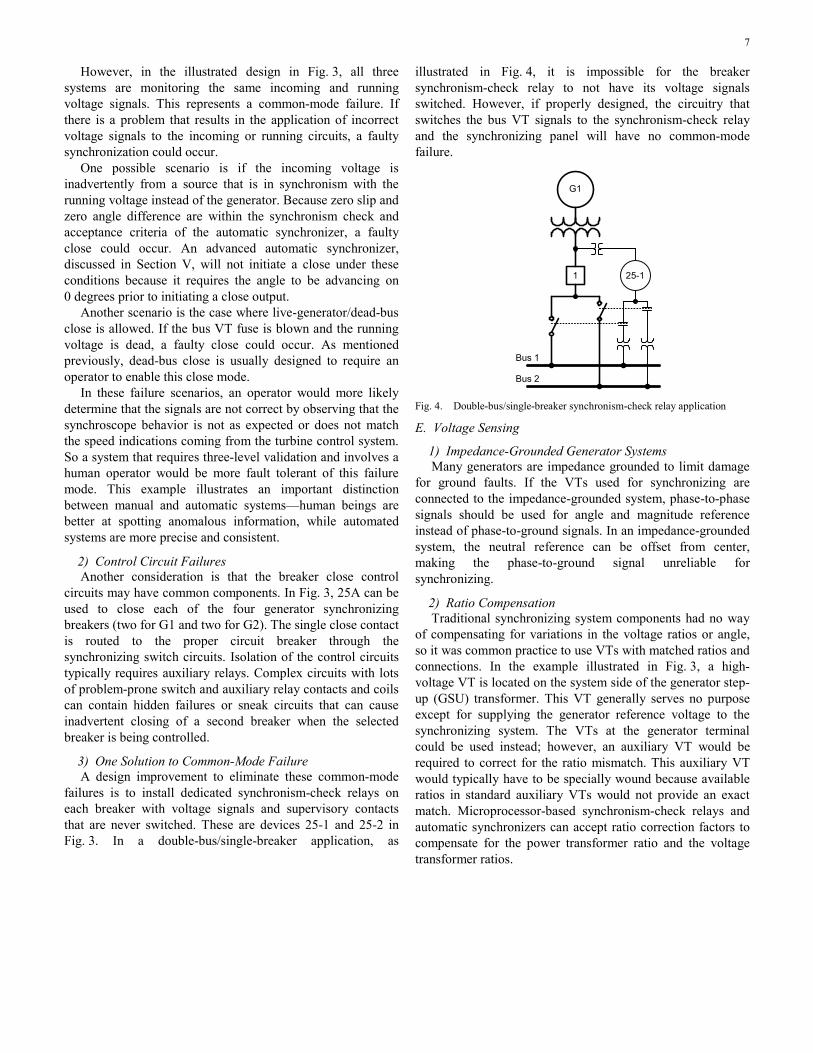
failures is to install dedicated synchronism-check relays on each breaker with voltage signals and supervisory contacts that are never switched. These are devices 25-1 and 25-2 in Fig. 3. In a double-bus/single-breaker application, as
illustrated in Fig. 4, it is impossible for the breaker synchronism-check relay to not have its voltage signals switched. However, if properly designed, the circuitry that switches the bus VT signals to the synchronism-check relay and the synchronizing panel will have no common-mode failure.
G1
1
Bus 1
Bus 2
25-1
Fig. 4. Double-bus/single-breaker synchronism-check relay application
E. Voltage Sensing
1) Impedance-Grounded Generator Systems Many generators are impedance grounded to limit damage
for ground faults. If the VTs used for synchronizing are connected to the impedance-grounded system, phase-to-phase signals should be used for angle and magnitude reference instead of phase-to-ground signals. In an impedance-grounded system, the neutral reference can be offset from center, making the phase-to-ground signal unreliable for synchronizing.
2) Ratio Compensation Traditional synchronizing system components had no way
of compensating for variations in the voltage ratios or angle, so it was common practice to use VTs with matched ratios and connections. In the example illustrated in Fig. 3, a high-voltage VT is located on the system side of the generator step-up (GSU) transformer. This VT generally serves no purpose except for supplying the generator reference voltage to the synchronizing system. The VTs at the generator terminal could be used instead; however, an auxiliary VT would be required to correct for the ratio mismatch. This auxiliary VT would typically have to be specially wound because available ratios in standard auxiliary VTs would not provide an exact match. Microprocessor-based synchronism-check relays and automatic synchronizers can accept ratio correction factors to compensate for the power transformer ratio and the voltage transformer ratios.
8
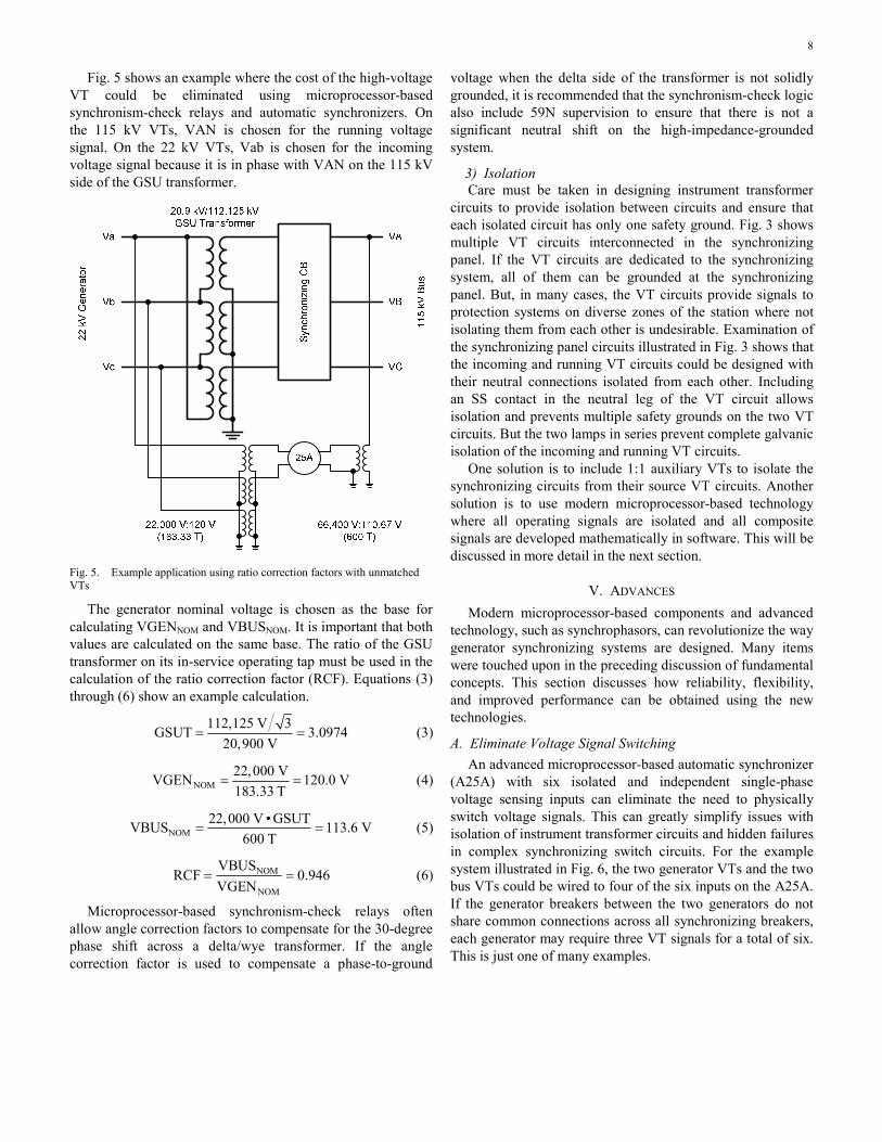
Fig. 5 shows an example where the cost of the high-voltage VT could be eliminated using microprocessor-based synchronism-check relays and automatic synchronizers. On the 115 kV VTs, VAN is chosen for the running voltage signal. On the 22 kV VTs, Vab is chosen for the incoming voltage signal because it is in phase with VAN on the 115 kV side of the GSU transformer.
Fig. 5. Example application using ratio correction factors with unmatched VTs
The generator nominal voltage is chosen as the base for calculating VGENNOM and VBUSNOM. It is important that both values are calculated on the same base. The ratio of the GSU transformer on its in-service operating tap must be used in the calculation of the ratio correction factor (RCF). Equations (3) through (6) show an example calculation.
112,125 V 3GSUT 3.097420,900 V
= = (3)
NOM22,000 VVGEN 120.0 V183.33 T
= = (4)
NOM22,000 V • GSUTVBUS 113.6 V
600 T= = (5)
NOM
NOM
VBUSRCF 0.946
VGEN= = (6)
Microprocessor-based synchronism-check relays often allow angle correction factors to compensate for the 30-degree phase shift across a delta/wye transformer. If the angle correction factor is used to compensate a phase-to-ground
voltage when the delta side of the transformer is not solidly grounded, it is recommended that the synchronism-check logic also include 59N supervision to ensure that there is not a significant neutral shift on the high-impedance-grounded system.
3) Isolation Care must be taken in designing instrument transformer
circuits to provide isolation between circuits and ensure that each isolated circuit has only one safety ground. Fig. 3 shows multiple VT circuits interconnected in the synchronizing panel. If the VT circuits are dedicated to the synchronizing system, all of them can be grounded at the synchronizing panel. But, in many cases, the VT circuits provide signals to protection systems on diverse zones of the station where not isolating them from each other is undesirable. Examination of the synchronizing panel circuits illustrated in Fig. 3 shows that the incoming and running VT circuits could be designed with their neutral connections isolated from each other. Including an SS contact in the neutral leg of the VT circuit allows isolation and prevents multiple safety grounds on the two VT circuits. But the two lamps in series prevent complete galvanic isolation of the incoming and running VT circuits.
One solution is to include 1:1 auxiliary VTs to isolate the synchronizing circuits from their source VT circuits. Another solution is to use modern microprocessor-based technology where all operating signals are isolated and all composite signals are developed mathematically in software. This will be discussed in more detail in the next section.
V. ADVANCES Modern microprocessor-based components and advanced
technology, such as synchrophasors, can revolutionize the way generator synchronizing systems are designed. Many items were touched upon in the preceding discussion of fundamental concepts. This section discusses how reliability, flexibility, and improved performance can be obtained using the new technologies.
A. Eliminate Voltage Signal Switching An advanced microprocessor-based automatic synchronizer
(A25A) with six isolated and independent single-phase voltage sensing inputs can eliminate the need to physically switch voltage signals. This can greatly simplify issues with isolation of instrument transformer circuits and hidden failures in complex synchronizing switch circuits. For the example system illustrated in Fig. 6, the two generator VTs and the two bus VTs could be wired to four of the six inputs on the A25A. If the generator breakers between the two generators do not share common connections across all synchronizing breakers, each generator may require three VT signals for a total of six. This is just one of many examples.
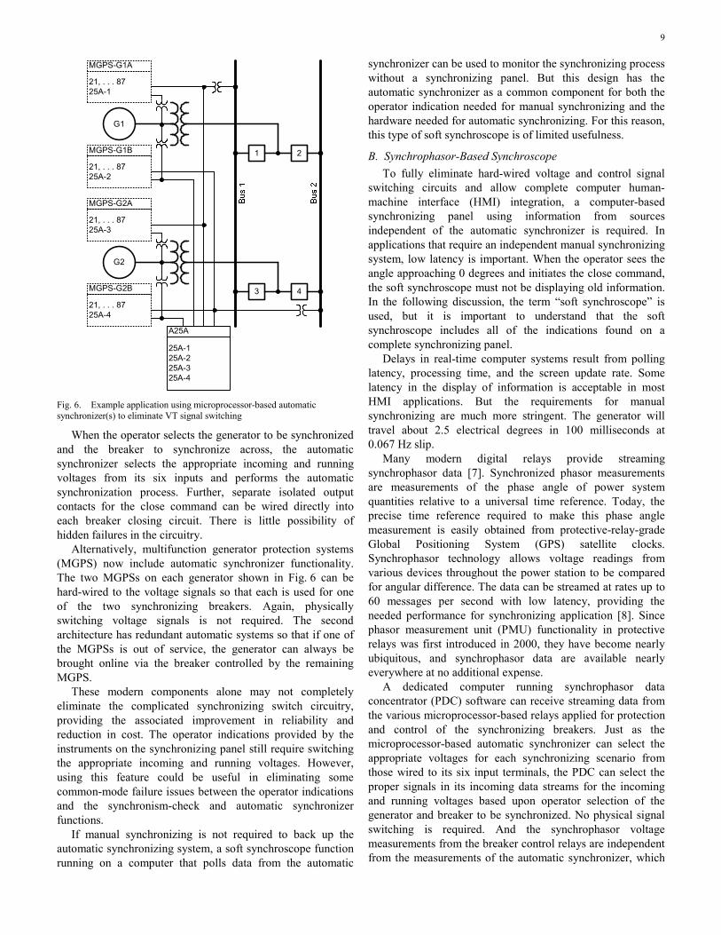
9
G1
G2
1 2
3 4
MGPS-G1A
21, . . . 8725A-1
MGPS-G1B
21, . . . 8725A-2
MGPS-G2A
21, . . . 8725A-3
MGPS-G2B
21, . . . 8725A-4
A25A
25A-125A-225A-325A-4
Fig. 6. Example application using microprocessor-based automatic synchronizer(s) to eliminate VT signal switching
When the operator selects the generator to be synchronized and the breaker to synchronize across, the automatic synchronizer selects the appropriate incoming and running voltages from its six inputs and performs the automatic synchronization process. Further, separate isolated output contacts for the close command can be wired directly into each breaker closing circuit. There is little possibility of hidden failures in the circuitry.
Alternatively, multifunction generator protection systems (MGPS) now include automatic synchronizer functionality. The two MGPSs on each generator shown in Fig. 6 can be hard-wired to the voltage signals so that each is used for one of the two synchronizing breakers. Again, physically switching voltage signals is not required. The second architecture has redundant automatic systems so that if one of the MGPSs is out of service, the generator can always be brought online via the breaker controlled by the remaining MGPS.
These modern components alone may not completely eliminate the complicated synchronizing switch circuitry, providing the associated improvement in reliability and reduction in cost. The operator indications provided by the instruments on the synchronizing panel still require switching the appropriate incoming and running voltages. However, using this feature could be useful in eliminating some common-mode failure issues between the operator indications and the synchronism-check and automatic synchronizer functions.
If manual synchronizing is not required to back up the automatic synchronizing system, a soft synchroscope function running on a computer that polls data from the automatic
synchronizer can be used to monitor the synchronizing process without a synchronizing panel. But this design has the automatic synchronizer as a common component for both the operator indication needed for manual synchronizing and the hardware needed for automatic synchronizing. For this reason, this type of soft synchroscope is of limited usefulness.
B. Synchrophasor-Based Synchroscope To fully eliminate hard-wired voltage and control signal
switching circuits and allow complete computer human-machine interface (HMI) integration, a computer-based synchronizing panel using information from sources independent of the automatic synchronizer is required. In applications that require an independent manual synchronizing system, low latency is important. When the operator sees the angle approaching 0 degrees and initiates the close command, the soft synchroscope must not be displaying old information. In the following discussion, the term “soft synchroscope” is used, but it is important to understand that the soft synchroscope includes all of the indications found on a complete synchronizing panel.
Delays in real-time computer systems result from polling latency, processing time, and the screen update rate. Some latency in the display of information is acceptable in most HMI applications. But the requirements for manual synchronizing are much more stringent. The generator will travel about 2.5 electrical degrees in 100 milliseconds at 0.067 Hz slip.
Many modern digital relays provide streaming synchrophasor data [7]. Synchronized phasor measurements are measurements of the phase angle of power system quantities relative to a universal time reference. Today, the precise time reference required to make this phase angle measurement is easily obtained from protective-relay-grade Global Positioning System (GPS) satellite clocks. Synchrophasor technology allows voltage readings from various devices throughout the power station to be compared for angular difference. The data can be streamed at rates up to 60 messages per second with low latency, providing the needed performance for synchronizing application [8]. Since phasor measurement unit (PMU) functionality in protective relays was first introduced in 2000, they have become nearly ubiquitous, and synchrophasor data are available nearly everywhere at no additional expense.
A dedicated computer running synchrophasor data concentrator (PDC) software can receive streaming data from the various microprocessor-based relays applied for protection and control of the synchronizing breakers. Just as the microprocessor-based automatic synchronizer can select the appropriate voltages for each synchronizing scenario from those wired to its six input terminals, the PDC can select the proper signals in its incoming data streams for the incoming and running voltages based upon operator selection of the generator and breaker to be synchronized. No physical signal switching is required. And the synchrophasor voltage measurements from the breaker control relays are independent from the measurements of the automatic synchronizer, which
10
makes the systems redundant. The PDC can also scale the voltage signals, if necessary.
For the manual system, it should be noted that the soft synchroscope provides visualization of the critical synchronizing quantities only. The operator still requires direct acting controls for the governor and exciter and for closing the breaker. Initiating a zero-degree close command via an HMI control point will typically include more latency than is acceptable.
Prior to the availability of a PDC synchroscope, the synchronizing panel needed to be physically close to the breakers and VTs providing the signals. Now, with fiber-optic data links, an operator can monitor and control the generator and breaker from a remote location. Further, high-performance, relay-to-relay logic communication in the A25A device allow it to be located close to the synchronizing breaker with control signals sent back to the governor and exciter via fiber-optic links.
The ability to build systems for monitoring and control using low-cost, fiber-optic communications links completely revolutionizes the design of generator synchronizing systems. The possibilities for system configurations that were never before possible are now nearly limitless. Section VI of this paper describes several configurations.
C. Improving Operator Indications The traditional synchronizing panel is not ideal because of
the limitations of electromechanical technology. Modern technology is no longer bounded by these limitations. The critical synchronizing quantities are:
• Angle difference. • Voltage difference. • Slip (frequency difference).
While the angle difference is directly indicated on the synchroscope, a traditional synchronizing panel typically does not include direct indication of the other two parameters. To determine voltage difference, the operator has to read the two voltmeters and mentally subtract the readings. To determine slip, the operator has to observe the synchroscope rpm. There is no direct indication of voltage difference and slip.
A traditional synchronizing panel can be enhanced by using indications from an advanced synchronism-check relay. The synchronism-check relay can be programmed to close a contact that lights an indicating lamp when the slip is within the acceptance range. Similarly, with programming, some relays can close a contact when the voltage difference is within the acceptance range. These two indications help the operator determine if the close attempt will be successful or blocked by the synchronism-check relay.
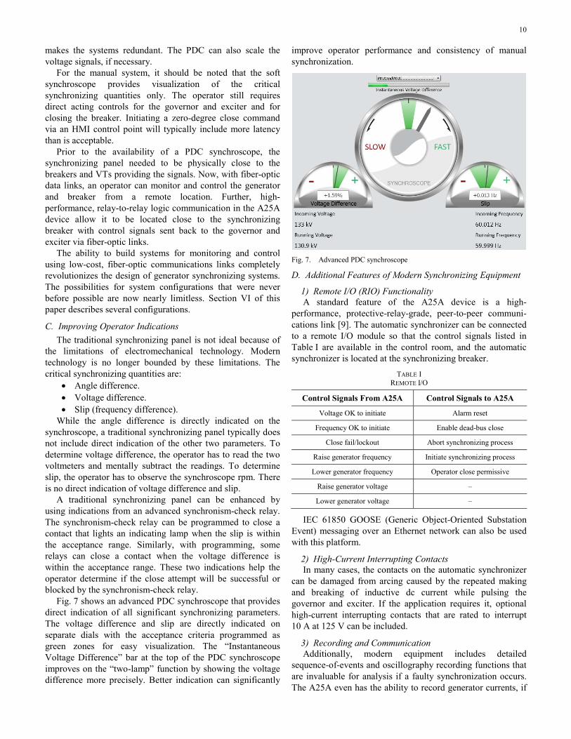
Fig. 7 shows an advanced PDC synchroscope that provides direct indication of all significant synchronizing parameters. The voltage difference and slip are directly indicated on separate dials with the acceptance criteria programmed as green zones for easy visualization. The “Instantaneous Voltage Difference” bar at the top of the PDC synchroscope improves on the “two-lamp” function by showing the voltage difference more precisely. Better indication can significantly
improve operator performance and consistency of manual synchronization.
Fig. 7. Advanced PDC synchroscope
D. Additional Features of Modern Synchronizing Equipment
1) Remote I/O (RIO) Functionality A standard feature of the A25A device is a high-
performance, protective-relay-grade, peer-to-peer communi-cations link [9]. The automatic synchronizer can be connected to a remote I/O module so that the control signals listed in Table I are available in the control room, and the automatic synchronizer is located at the synchronizing breaker.
TABLE I REMOTE I/O
Control Signals From A25A Control Signals to A25A
Voltage OK to initiate Alarm reset
Frequency OK to initiate Enable dead-bus close
Close fail/lockout Abort synchronizing process
Raise generator frequency Initiate synchronizing process
Lower generator frequency Operator close permissive
Raise generator voltage –
Lower generator voltage –
IEC 61850 GOOSE (Generic Object-Oriented Substation Event) messaging over an Ethernet network can also be used with this platform.
2) High-Current Interrupting Contacts In many cases, the contacts on the automatic synchronizer
can be damaged from arcing caused by the repeated making and breaking of inductive dc current while pulsing the governor and exciter. If the application requires it, optional high-current interrupting contacts that are rated to interrupt 10 A at 125 V can be included.
3) Recording and Communication Additionally, modern equipment includes detailed
sequence-of-events and oscillography recording functions that are invaluable for analysis if a faulty synchronization occurs. The A25A even has the ability to record generator currents, if
11
they are wired to it, during each synchronization to gauge the smoothness or severity of the operation. This level of information is also invaluable when determining if tear down and inspection is required after a faulty synchronization.
A system that uses synchrophasors can also have the PDC archive the synchrophasor data from the synchronizing process to help with analysis of operator performance, tuning of the automatic synchronizer control parameters, and so on.
The A25A records the correction pulse duration and the resulting ΔV and ΔF from each correction pulse. When commissioning the system, the seconds-per-hertz and seconds-per-volt response characteristics of the governor and exciter can be calculated and graphed. This information is useful to optimize the proportional pulse slope characteristics of the control.
E. Slow Synchronizing Breaker Protection Calculation of the slip-compensated advanced angle to
cause a zero-degree close requires knowing the breaker closing mechanism delay. If the mechanical mechanism is consistent, precise and repeatable closing can be achieved. However, there have been cases reported of generator breakers that were slow to close [5]. Excessive delay between the time when the close coil is energized and the main contacts close can allow the generator to advance beyond the safe angle limits, resulting in a faulty synchronization. Once the close coil is energized and the close mechanism has been released, the close cannot be stopped and the angle when the contacts make is impossible to predict.
One method to mitigate this risk is to exercise the synchronizing breaker prior to using it for synchronizing. Often, the slow operation is caused by a sticky valve or excessive friction in the mechanism, and the trial operation frees things up so that the next closing operation is within specifications. There is no easy way to measure the breaker closing time for the trial close to determine that it is within specifications. This method provides no guarantee that the actual synchronizing close will be within specifications.
The only way to guarantee that a generator system does not close out of synchronism because of a slow synchronizing breaker is to monitor the angle after the close coil is energized. If the angle advances outside the acceptable range, an output contact trips the breaker failure lockout relay of the synchronizing breaker. This opens all of the breakers around the slow breaker so that, when it eventually closes, the generator is closed onto a dead bus [10]. This protective function is easily implemented with modern programmable relays.
VI. EXAMPLES The following are several example applications using
advanced synchronizing systems. Some of these applications are in service and some have only been proposed.
A. No Local Synchronizing Breaker In this application, a combustion turbine generator is
located several miles from the substation that ties it to the
grid. The installation does not include a local synchronizing breaker. In the past, there would be no way to provide synchronizing panel indications from the VTs located at the substation to the generator control room. The proposed system included an A25A device located at the substation with a RIO located in the control room to adjust the governor and exciter via a fiber-optic link and to take operator control signals for initiate and abort to the A25A. A PDC synchroscope for operator visualization and control and a separate RIO for taking the operator close signal to the remote breaker close coil were included as options.
B. Multiple Synchronizing Points in Reliability Islanding System
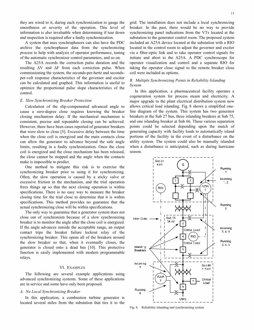
In this application, a pharmaceutical facility operates a cogeneration system for process steam and electricity. A major upgrade to the plant electrical distribution system now allows critical load islanding. Fig. 8 shows a simplified one-line diagram of the system. This system has two generator breakers at the Sub 27 bus, three islanding breakers at Sub 75, and one islanding breaker at Sub 66. These various separation points could be selected depending upon the match of generating capacity with facility loads to automatically island portions of the facility in the event of a disturbance on the utility system. The system could also be manually islanded when a disturbance is anticipated, such as during hurricane season.
Fig. 8. Reliability islanding and synchronizing system
12
Sub 75 and Sub 27 are within a few hundred yards of each other, so the synchronizing voltages for Breakers 3, 4, and 5 were wired directly to device A25A-1. Closing commands from A25A-1 were sent to Sub 75 using a RIO and fiber-optic link to maintain isolation between the battery systems at the two substations. Sub 66 is about a half mile from Sub 27, so A25A-2 was located there to synchronize across Breaker 6. Raise and lower pulses were sent to Sub 27 using a RIO and fiber-optic link. Automatic synchronizing is the only system allowed at this facility, so no soft synchroscope is installed.
The system is completely controlled via an HMI system in the Sub 27 control room. All of the original synchronizing switch wiring was removed in the upgrade.
C. Elimination of Synchronizing Circuits in a Paper Mill A paper mill operates a cogeneration system for process
steam and electricity. The system includes multiple generators and multiple synchronizing points throughout a complex plant distribution system. All synchronizing circuits go through a single synchronizing cabinet with a complicated arrangement of auxiliary relays and selector switch contacts to set up the various synchronizing scenarios. The plant environment causes corrosion problems for electrical components, so there are frequent failures of components in the synchronizing cabinet. Due to the complexity of the circuitry and the large number of hidden failure points, troubleshooting can be very difficult and time-consuming, resulting in reduced availability of critical generation.
This facility also has a utility tie circuit breaker that is remote from the generator control room. It is sometimes necessary to synchronize the islanded facility back to the utility at that location. Conventional synchronizing technology results in long VT and control circuits running between the electrical substations and poor system reliability.
Modern microprocessor-based equipment can be conformal coated to provide resistance to degradation in harsh industrial environments. Eliminating auxiliary relays and switching contacts and performing all sensing and control signal switching in software can greatly improve the reliability of the synchronizing system.
A system upgrade is planned to install a remote A25A at the utility tie substation using a RIO to bring control signals back to the control room. In phase two, the existing synchronizing cabinet can be replaced with a number of A25A devices.
D. Redundant Automatic Synchronizing System With Complex Bus and Multiple Synchronizing Scenarios
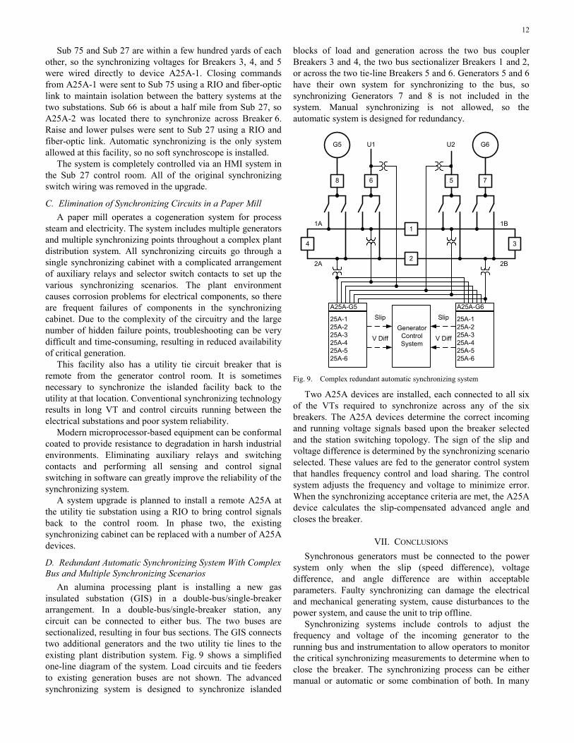
An alumina processing plant is installing a new gas insulated substation (GIS) in a double-bus/single-breaker arrangement. In a double-bus/single-breaker station, any circuit can be connected to either bus. The two buses are sectionalized, resulting in four bus sections. The GIS connects two additional generators and the two utility tie lines to the existing plant distribution system. Fig. 9 shows a simplified one-line diagram of the system. Load circuits and tie feeders to existing generation buses are not shown. The advanced synchronizing system is designed to synchronize islanded
blocks of load and generation across the two bus coupler Breakers 3 and 4, the two bus sectionalizer Breakers 1 and 2, or across the two tie-line Breakers 5 and 6. Generators 5 and 6 have their own system for synchronizing to the bus, so synchronizing Generators 7 and 8 is not included in the system. Manual synchronizing is not allowed, so the automatic system is designed for redundancy.
G5
8
U1
4
6
1
2
3
75
G6U2
A25A-G5
25A-125A-225A-3 25A-425A-5 25A-6
A25A-G6
25A-125A-225A-325A-4 25A-525A-6
GeneratorControl System
Slip
V Diff
Slip
V Diff
1A
2A
1B
2B
Fig. 9. Complex redundant automatic synchronizing system
Two A25A devices are installed, each connected to all six of the VTs required to synchronize across any of the six breakers. The A25A devices determine the correct incoming and running voltage signals based upon the breaker selected and the station switching topology. The sign of the slip and voltage difference is determined by the synchronizing scenario selected. These values are fed to the generator control system that handles frequency control and load sharing. The control system adjusts the frequency and voltage to minimize error. When the synchronizing acceptance criteria are met, the A25A device calculates the slip-compensated advanced angle and closes the breaker.
VII. CONCLUSIONS Synchronous generators must be connected to the power
system only when the slip (speed difference), voltage difference, and angle difference are within acceptable parameters. Faulty synchronizing can damage the electrical and mechanical generating system, cause disturbances to the power system, and cause the unit to trip offline.
Synchronizing systems include controls to adjust the frequency and voltage of the incoming generator to the running bus and instrumentation to allow operators to monitor the critical synchronizing measurements to determine when to close the breaker. The synchronizing process can be either manual or automatic or some combination of both. In many

13
cases, when an automatic system is installed, the manual system is maintained as a backup to the automatic system.
Automatic systems have the advantage of greater precision and repeatability in calculating the slip-compensated advanced angle to energize the close coil and cause the main contacts of the breaker to close at 0 degrees. Human operators have the advantage of better recognizing abnormal conditions and errors in the synchronizing indications. Systems that require both operator and automatic synchronizer to initiate the breaker close take advantage of these complementary attributes.
Synchronizing systems also include supervisory relays such as synchronism-check and voltage relays to prevent synchronization errors from causing a generator breaker to be closed out of phase. Modern microprocessor-based synchronism-check relays properly monitor both angle and slip and are an improvement over earlier technology synchronism-check relays for generator application. These relays can compensate for differences in VT transformation ratios.
Designing a robust and fault-tolerant synchronizing system is challenging. The system should have no single points of failure or common-mode failure problems. The instrument transformer circuits must have proper isolation and grounding. Similarly, the dc control circuits must also have proper isolation. Usually, the only way to achieve this with conventional technology is with problem-prone auxiliary VTs and auxiliary relays. Modern advanced automatic synchronizers with software switching of up to six voltage signals and local and remote output contacts simplifies the design process.
The synchronizing panel is often the last remaining item that still requires complex synchronizing switch circuits. A synchrophasor-based soft synchroscope running on a PDC can modernize the operator interface. The modern synchroscope provides better indications than were possible with traditional technology and that enables the operator to perform more accurately and consistently. The PDC-based synchronizing panel enables opportunities for synchronizing system designs that were never possible before.
VIII. ACKNOWLEDGMENT The author gratefully acknowledges the contribution of
Greg Zweigle and the distributed coherent systems engineering group at Schweitzer Engineering Laboratories, Inc. for developing the concept of the soft synchroscope described in Section IV, Subsection C of this paper. Bradon Kovaly and Matt Macdonald provided an initial implementation of the synchroscope.
IX. REFERENCES [1] IEEE Standard for Salient-Pole 50 Hz and 60 Hz Synchronous
Generators and Generator/Motors for Hydraulic Turbine Applications Rated 5 MVA and Above, IEEE Standard C50.12-2005.
[2] IEEE Standard for Cylindrical-Rotor 50 Hz and 60 Hz Synchronous Generators Rated 10 MVA and Above, IEEE Standard C50.13-2005.
[3] IEEE Guide for Operation and Maintenance of Turbine Generators, IEEE Standard 67-2005.
[4] IEEE Guide for AC Generator Protection, IEEE Standard C37.102-2006.
[5] W. M. Strang, C. J. Mozina, B. Beckwith, T. R. Beckwith, S. Chhak, E. C. Fennell, E. W. Kalkstein, K. C. Kozminski, A. C. Pierce, P. W. Powell, D. W. Smaha, J. T. Uchiyama, S. M. Usman, and W. P. Waudby, “Generator Synchronizing Industry Survey Results,” IEEE Transactions on Power Delivery, Vol. 11, Issue 1, pp. 174–183, Jan. 1996.
[6] R. A. Evans, “A Manual/Automatic Synchronization Circuit for a 37.5 MVA Steam-Turbine-Driven Generator,” IEEE Transactions on Industry Applications, Vol. 26, Issue 6, pp. 1081–1085, Nov./Dec. 1990.
[7] G. Benmouyal, E. O. Schweitzer, III, and A. Guzmán, “Synchronized Phasor Measurement in Protective Relays for Protection, Control, and Analysis of Electric Power Systems,” proceedings of the 29th Annual Western Protective Relay Conference, Spokane, WA, October 2002.
[8] K. Koellner, C. Anderson, and R. Moxley, “Generator Black Start Validation Using Synchronized Phasor Measurement,” proceedings of the 60th Annual Conference for Protective Relay Engineers, College Station, TX, March 2007.
[9] K. C. Behrendt, “Relay-to-Relay Digital Logic Communication for Line Protection, Monitoring, and Control,” proceedings of the 23rd Annual Western Protective Relay Conference, Spokane, WA, October 1996.
[10] L. C. Gross, L. S. Anderson, and R. C. Young, “Avoid Generator and System Damage Due to a Slow Synchronizing Breaker,” proceedings of the 24th Annual Western Protective Relay Conference, Spokane, WA, October 1997.
X. BIOGRAPHY Michael J. Thompson received his BS, magna cum laude, from Bradley University in 1981 and an MBA from Eastern Illinois University in 1991. He has broad experience in the field of power system operations and protection. Upon graduating, he served nearly 15 years at Central Illinois Public Service (now AMEREN), where he worked in distribution and substation field engineering before taking over responsibility for system protection engineering. Prior to joining Schweitzer Engineering Laboratories, Inc. (SEL) in 2001, he was involved in the development of several numerical protective relays while working at Basler Electric. He is presently a principal engineer in the engineering services division at SEL, a senior member of the IEEE, a main committee member of the IEEE PES Power System Relaying Committee, and a registered professional engineer. Michael was a contributor to the reference book, Modern Solutions for the Protection, Control, and Monitoring of Electric Power Systems, has published numerous technical papers, and has a number of patents associated with power system protection and control.
© 2010 by Schweitzer Engineering Laboratories, Inc. All rights reserved.
20101209 • TP6459-01