Embed Size (px)
Citation preview
NSWCDD-MP-14-00380 is approved for Distribution Statement A:
Approved for Public Release; distribution is unlimited.
Functional Hazard Analysis (FHA)
Methodology Tutorial
International System Safety
Training Symposium
St. Louis, Missouri
4 - 8 August 2014
Mr. Adam Scharl
NSWCDD, 540-653-7940
Mr. Rani Kady, Ph.D.
NSWCDD, 540-653-2409
Mr. Kevin Stottlar
NSWCDD, 540-653-7301

2
NSWCDD-MP-14-00380 is approved for Distribution Statement A:
Approved for Public Release; distribution is unlimited.
Functional Hazard Analysis
Purpose:
The purpose of the FHA is to identify and classify the system functions and safety hazards,
environmental, and health-related consequences associated with functional failure or malfunction,
i.e., hazards (Military Standard (MIL-STD)-882E, Task 208). The FHA identifies the
relationships between functions and hazards, thereby identifying the safety-significant functions
(SSFs) of the system as well as the hazards associated with that functionality. This identification
provides a foundation for the safety program to scope additional safety analyses and level of
rigor (LOR) analysis and verification of the system software.
In general, conduct of the FHA provides the safety practitioner a perspective with which to
participate in functional definition of the system under analysis. The program should not expect
to have a complete list of functions or functional relationships defined when starting the FHA.
The FHA will help the safety program advise the program on function definition by identifying
likely functional hazards. The FHA will also start the mitigation solution discussion. If
mitigations can be planned at the functional level, the design will be more stable from a safety
perspective, decreasing the cost of safety mitigations by introducing them to the system design
early during the systems engineering process.
The FHA results in the identification of SSFs, safety-significant items (SSIs), hazards, and an
assessment of implementing functions in hardware, software, or human control interfaces;
recommended requirements and design constraints; and follow-on actions to be performed
during current or future system life-cycle phases. The SSFs and SSIs identify the system
functions and items (e.g., subsystems, components, and interfaces) that influence the safety of
the system.
The hazards identified during the FHA are described in terms of the function related to the
hazard(s), the potential mishap(s) and effect(s) (allowing for assessment of the mishap severity
of the identified hazards), and the system item(s) related to the hazard(s). The FHA also allows
for assessing the probability of mishap occurrence (for hardware/human related failures) or
software control (for potential software contributions) associated with the functional failure
constituting the hazard. Requirements and design constraints are recommended for inclusion in
the system specifications in order to eliminate or reduce the risk of the identified hazards, once
successfully implemented.
Background:
Systems Engineering (SE) processes emphasize the need to develop a system-functional
architecture during the conceptual system design phase. This functional architecture is derived
from the system’s problem definition, operational requirements, maintenance and support
concept, and technical performance measures. The functional architecture is developed prior to
3
NSWCDD-MP-14-00380 is approved for Distribution Statement A:
Approved for Public Release; distribution is unlimited.
any definition of the system physical architecture, and defines “what” the system needs to do, as
opposed to “how” the system will do those things.
A function is defined as “a specific or discrete action (or series of actions) that is necessary to
achieve a given objective.”1 The functional architecture of a system identifies those functions,
and the relationships between those functions, necessary to provide the desired system capability.
System functions are identified through a process of functional decomposition; the high-level
system capability is broken down into successively more specific functions, resulting in a
functional hierarchy and functional flow block diagrams (FFBDs) that define the functional
architecture of the system.
Functional analysis, an SE process of developing a functional architecture, should include
coverage of all activities throughout the system life cycle and, as mentioned earlier, is concerned
with what is required of the system before looking at how it should be accomplished. The
functional architecture should be flexible to allow for expansion if additional definition is
required. The objective of functional analysis is to “progressively and systematically work down
to the level where resources (human, hardware, software items) can be identified with how a task
should be accomplished.”1
With the functional architecture established, SE develops the physical architecture of the system
to identify “how” the system will implement the functions contained within the functional
architecture. This physical architecture also relies upon a decomposition of the system, this time
with a focus on the subsystems and components that make up the overall system.
The Department of Defense Architecture Framework (DoDAF) serves as a tool for documenting
system architectures (functional and physical). DoDAF defines a common approach for
describing, presenting, and comparing Department of Defense (DoD) system architectures;
facilitates the use of common principles, assumptions, and terminologies; and ensures that
architecture descriptions can be compared and related across organizational boundaries,
including Joint and multi-national boundaries.
DoDAF defines various “views,” each of which documents a different aspect of the system
architecture. Each of these views is associated with one of the following viewpoints:
All Viewpoint (AV): overarching information describing the architecture such as plans,
scope, time frame, goals, scenarios, Concept of Operations (CONOPS), and definitions.
Operational Viewpoint (OV): captures the organizations, activities performed, and
information that must be exchanged between them to accomplish DoD missions
(warfighting, business, intelligence, etc.).
Systems Viewpoint (SV): describes the systems, their interconnectivity, and their
functionality in support of operational activities.
Services Viewpoint (SvcV): service-oriented equivalent of SV.
1 Blanchard and Fabricky, Systems Engineering and Analysis, 2006.

4
NSWCDD-MP-14-00380 is approved for Distribution Statement A:
Approved for Public Release; distribution is unlimited.
Data and Information Viewpoint (DIV): business information requirements and
structural process rules; describes the information that is associated with the information
exchanges such as attributes, characteristics, and interrelationships.
Standards View (StdV): rules governing the arrangement, interaction, and
interdependence of system parts or elements; policies, standards, and constraints;
business, technical, operational.
Capability Viewpoint (CV): enterprise goals for the overall vision for executing a
specified course of action - the ability to achieve a desired effect under specific standards
and conditions through combinations of means and ways to perform a set of tasks;
strategic context and higher-level scope than operational concept.
Project Viewpoint (PV): captures how acquisition programs are grouped in
organizational terms as a coherent portfolio; describes the organizational relationships
between programs.
The remainder of this section describes a handful of DoDAF views that facilitate conduct of the
FHA. While conduct of an FHA is not dependent on the existence of these views in particular,
conduct of the FHA does rely upon the system description/information provided by these views.
For a full discussion of DoDAF views, DoD maintains a reference website at
http://dodcio.defense.gov/dodaf20.aspx
The High Level Operational Concept Graphic (OV-1) describes the system mission or scenario,
including main operations, interactions with the environment and external systems, and the
system boundary. The OV-1’s main role is to give context and aid discussion about the system.
The Operational Activity Decomposition Tree (OV-5a) and Operational Activity Model (OV-5b)
depict the solution-neutral functions and their relationships to each other, including input/output
flows and dependencies on one another. Operational activities are solution-neutral functions that
are eventually decomposed to system functions in the SV views. The distinction between
operational activities and system functions is beyond the scope of this document, but for the
purposes of the FHA operational activities may be considered as system functions to be
addressed as part of the analysis.
The Systems Functionality Description (SV-4) further documents the functional decomposition
of the system and the data flows between functions. Generation of the SV-4 helps the program
ensure that all functions receive needed resources/inputs and documents the functional
architecture of the system. The SV-4 may consist of a functional hierarchy (documenting the
functional decomposition of the system) and FFBDs (documenting the relationships and
resources/items passed between functions).
The Operational Activity to System Function Traceability Matrix (SV-5a) and Operational
Activity to Systems Traceability Matrix (SV-5b) describe the relationships between the
operational activities and system functions (further decomposition of the functional architecture)
and between the operational activities and the system items (the link between the functional and
physical architectures). The SV-5a and SV-5b may be combined (identified as the SV-5) to
identify the relationships between the system functions and items (subsystems/components).

5
NSWCDD-MP-14-00380 is approved for Distribution Statement A:
Approved for Public Release; distribution is unlimited.
Methodology:
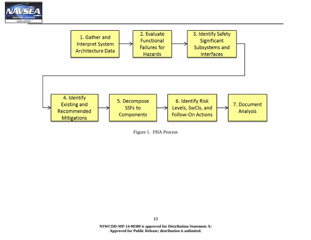
1. Gather and Interpret System Architecture Data
The first step of the FHA is to gather and interpret the system architecture data (i.e., the system
functional architecture) in order to identify and describe the functions that are performed by the
system. Functional definition of the system is an SE task but, ideally, should happen with
system safety engineering participation; early initiation of the FHA allows for safety
participation in system functional definition. At a minimum, safety engineering participation in
functional definition allows the safety practitioner to define the assumptions associated with the
system architecture and, in turn, the FHA.
The overall process of functional definition should result in, at a minimum, a functional
hierarchy, functional flow block diagrams, and a function/item matrix of the system. These
artifacts, which may be documented as the system SV-4 and SV-5, describe the system functions
(including their inputs and outputs), the relationship of the system functions to one another, and
the relationships between the system functions and the system items responsible for performing
those functions.
It is important for the safety practitioner to consider the system architecture in terms of accepted
use cases in order to evaluate the completeness of the given architecture. Use cases are nothing
more than a sequence of events that, taken as a whole, describe how a given system is expected
to meet certain goals. A particular use case should provide insight to the functions required to be
performed to meet the given goal and the system(s)/subsystem(s) required to perform those
functions. For the purposes of this discussion, a use case is something that may be used to
evaluate the completeness of a system’s architecture (e.g., the OV-1 and SV-4).
At this stage of the FHA process, system items may be defined as the subsystems that make up
the overall system. This level of definition allows the safety practitioner to assess the system
functions for safety impact and allocate those functions to the appropriate subsystem (see Steps 2
and 3). Further decomposition of subsystems to components must then be addressed as the
analysis progresses. The FHA level of detail evolves with the functional and physical
decomposition of the system; an early understanding of the subsystem relationships is essential
to establishing a foundation for further decomposition of the safety functions.
Enter each system function, at all available levels, as its own row in the FHA worksheet. This
process ensures that all functions are fully assessed by the FHA.
2. Evaluate Functional Failures for Hazards
The next step of the FHA is to evaluate functional failures for hazards; the safety practitioner
must evaluate each function documented in the FHA worksheet for the impact of functional
failure. This evaluation must consider all of the life-cycle phases, activities, and states/modes
applicable to the system under assessment and a given functional failure’s potential impact in
each phase, activity, and state/mode combination. For example, the execution of maintenance
6
NSWCDD-MP-14-00380 is approved for Distribution Statement A:
Approved for Public Release; distribution is unlimited.
functions during a tactical state/mode may introduce hazards that do not apply to the execution
of maintenance functions with the system in an off state.
The safety practitioner must consider the following functional failure types for each function
under analysis:
1. Fails to operate: Function does not happen/perform when given the appropriate input.
2. Operates early/late: Function performs earlier or later than it should have; if too late,
function could be out of sequence.
3. Operates out of sequence: Function occurs before or after the wrong function; function
occurs without receiving the appropriate inputs.
4. Unable to stop operation: Function continues even though the thread should move on to
the next function.
5. Degraded function or malfunction: Function does not finish or only partially completes;
function generates improper output.
System safety practitioners who have been assessing hazards for a well-defined system may be
initially uncomfortable with assessing at the functional level. The results will have much less
detail compared to a subsystem hazard analysis or deficiency report safety analysis. However,
the results will be useful to both the program office and the system safety program as a tool to
identify and minimize safety risk early, lowering total costs.
The FHA worksheet provides the safety practitioner with a tool to ensure complete coverage of
the system functions and full evaluation of functional failures. This process recommends
expanding the worksheet rows by entering each function as its own row, and then expanding
even further by allocating each functional failure type to each function under assessment. When
completing a worksheet row, multiple hazards may be associated with a given functional failure;
also, multiple mishaps and effects may be associated with a given hazard. Splitting a row in to
multiple entries will be driven by the difference in mitigations that can be applied to risk
reduction of a particular hazard, and may not be obvious during this step of the analysis.
The safety practitioner may use the Energy Trace Barrier Analysis (ETBA) framework for
assessing functional failures for safety impact. ETBA within the FHA relies on identification of
the energy within a system function and the functional barriers that control that energy from
being released. Combining the ETBA framework with the FHA process helps ensure the
completeness of this particular safety analysis.
Using the ETBA framework, each functional failure must be assessed for safety impact. This
assessment should be summarized in the “Comments” field of the FHA worksheet for future
reference. Document any functional failures assessed “not safety” as such by entering “N/A” in
the “Hazard Description,” “Mishap,” and “Effect(s)” fields.
Also during this step, hazards associated with the functional failure must be characterized in
accordance with the applicable hazard tracking database fields, which should be documented in
the program’s System Safety Program Plan. This involves documenting the hazard description

7
NSWCDD-MP-14-00380 is approved for Distribution Statement A:
Approved for Public Release; distribution is unlimited.
of the functional failure, the mishap associated with the identified hazard, and the effect(s) that
result from the occurrence of the mishap.
Those functions that have been assessed as having a functional failure which constitutes a hazard
are defined as SSFs of the system. Note: participating in functional definition (see Step 2)
allows the safety program to define the SSFs in accordance with the system documentation as
developed by SE. This allows the safety program to maintain common language with SE, but
also allows for the identification and documentation of SSFs within SE artifacts. Establishing
and maintaining common language between SE and system safety engineering is an important
benefit of the FHA.
3. Identify Safety-Significant Subsystems and Interfaces
The next step requires the correlation of the system SSFs and the subsystems and interfaces
associated with the execution of those functions. This correlation may be documented in system
architecture documentation (the SV-5, in particular); this process relies on adequate
documentation on the part of SE. If the system under analysis does not have a documented SV-5,
the safety practitioner must work with SE to develop an equivalent in order to complete this step
of the FHA process.
This step allows the safety practitioner to identify the subsystems associated with the hazards
identified in Step 2. Ideally, initial functional decomposition provided the safety practitioner
with functions allocated to a minimum number of subsystems. This ideal situation would result
in a clear relationship between the subsystems and the identified hazards (again, ideally, one
subsystem would be associated with each function and, therefore, hazard). If multiple
subsystems are associated with a given function, and therefore hazard, the safety practitioner
must work with SE to decompose the given function to a lower level that clarifies the role of
each subsystem within that function; decomposition of the associated hazard must then be
accomplished.
Enter the appropriate subsystem(s) and interface(s) in the “System Item” field for each hazard.
Those items allocated to an SSF are defined as SSIs of the system. The identified safety-
significant subsystems (and their associated SSFs) will be used to identify safety-significant
components later in the FHA process (see Step 5).
4. Identify Existing and Recommended Mitigations
At this point, the safety practitioner has fully characterized the functional failures of the system,
including the hazard(s), mishap(s), and subsystem(s) associated with those failures.
Characterizing hazards early in the system design process allows the safety practitioner to
recommend system design changes to eliminate or control the hazards identified up to this point.
For each identified hazard, the safety practitioner must identify the existing and recommended
requirements and/or design constraints to assess, reduce, and/or eliminate the mishap risk
associated with the given hazard. These requirements and constraints may be in the form of fault
tolerance, detection, isolation, annunciation, or recovery. In order to fully document the existing

8
NSWCDD-MP-14-00380 is approved for Distribution Statement A:
Approved for Public Release; distribution is unlimited.
mitigations identified during this analysis, the safety practitioner must document them in the
“Existing Mitigations” field of the appropriate hazard row in the FHA worksheet; the safety
practitioner must document the recommended mitigations in the “Recommended Mitigations”
field of the appropriate hazard row in the FHA worksheet.
The identification of recommended requirements and design constraints allows the safety
practitioner to assess the anticipated impact of those requirements and design constraints on the
mishap risk of the system hazards.
5. Decompose SSFs to Components
As the system progresses through design, the system functions are further decomposed and
allocated to subsystem components, resulting in a complete functional baseline. Components,
for the purposes of this discussion, are defined as physical system items that are distinctly
hardware, software, or human. Participating in functional decomposition to the component level
allows the safety practitioner to ensure that the SSFs are appropriately implemented at the next
level of system design. Ensuring that components are uniquely of one and only one type (i.e.,
hardware, software, or human) ensures that each component’s contribution to overall system risk
may be assessed appropriately. Risk assessment is further described in Step 6.
Each of the subsystem-level SSFs identified during Step 3 must be decomposed to the
component level. This requires an understanding of the functional architecture at the component
level (i.e., how component functions interact to perform subsystem functions) and analysis of
functional failures at the component level to further characterize previously identified hazards
and identify new hazards. This step results in the identification of safety-significant components
and the recommendation of requirements and design constraints at the component level.
An important aspect of this step is the identification of component-level causal factors that relate
to the subsystem-level hazards previously identified; functional failures at the component level
must be considered in terms of the previously assessed functional failures at the
system/subsystem level. Any component-level functional failures identified as contributing to
subsystem-level functional failures (hazards) must be documented in the “Causal Factor
Description” field of the applicable hazard row in the FHA worksheet; component-level
functional failures identified as new hazards must be documented as a unique hazard record.
Similar to the subsystem-level allocation, each functional failure at the component level should
be associated with a single component. For those functions allocated to multiple components,
further functional decomposition is required to understand the contribution of each component to
the performance of that function. Those further decomposed functions may then be assessed to
identify the functional failures that constitute a hazard or causal factor. Ideally, each component-
level functional failure that constitutes a hazard or causal factor will be allocated to a single
component at the conclusion of this step.
6. Identify Risk Levels, Software Criticality Indices (SwCIs), and Follow-On Actions
9
NSWCDD-MP-14-00380 is approved for Distribution Statement A:
Approved for Public Release; distribution is unlimited.
With functional hazards and causal factors identified at all system levels and allocated to the
applicable components, the safety practitioner must assess each for safety impact. This
assessment includes consideration of the mishaps associated with the given hazards and causal
factors in order to understand the severity of the associated mishap(s) and the hazards’
contribution to the probability of those mishaps occurring.
For all identified hazards, the safety practitioner must assess the probability of mishap
occurrence associated with the existence of the given hazard. This assessment should be
performed at the lowest possible system level (i.e., component-level functional failure) and will
require different considerations depending on the type of component associated with the given
hazards and causal factors (called “safety issues” for the rest of this paragraph). Safety issues
associated with hardware failures may be considered in terms of the probability that the hardware
will fail; software failures must be assessed in terms of the softwares level of control over
hazardous hardware (see the Software Safety Workshop for further discussion of Software
Control Category and SwCI assessments); human failures may be considered in terms of the
probability of operator error. It is important to note that these assessments will likely require
further refinement through more detailed safety analyses (i.e., Subsystem, Software Safety and
Operations and Support hazard analyses). Assessment of system safety risk is outside the scope
of this tutorial.
7. Document Analysis
Per Naval Sea Systems Command Instruction (NAVSEAINST) 5100.12B, a draft FHA report is
required for the final System Requirements Review (SRR) and the System Functional Review
(SFR); a final report is required at the Preliminary Design Review (PDR). The methodology up
to this point allows for generation of the final FHA report for PDR.
The final FHA report, in accordance with MIL-STD-882E, must provide a system description in
terms of the physical and functional characteristics of the system, its subsystems, and the
components that make up those subsystems. The safety practitioner must ensure that the system
architecture documentation is included or referenced in the FHA report. The report must also
describe the methodology used during conduct of the FHA and summarize the results of the
analysis. This summary may include a list of the SSFs and SSIs, a table of the SwCIs associated
with the system software components, and/or a summary of the recommended requirements and
design constraints identified during the analysis.
10
NSWCDD-MP-14-00380 is approved for Distribution Statement A:
Approved for Public Release; distribution is unlimited.
Figure 1. FHA Process

11
NSWCDD-MP-14-00380 is approved for Distribution Statement A:
Approved for Public Release; distribution is unlimited.
Table 1. FHA Process Tasks
Task Task Description
FHA
Worksheet
Column(s)
Considerations References
1. Gather and interpret
system architecture
data
Collect the inputs needed to
conduct the FHA and evaluate
for completeness.
N/A Work with SE to collect and
evaluate system architecture
documentation
N/A
1.a: Collect available
system architecture
models
Collect system architecture
documentation.
None Architecture should address the
functions of the system, including
the functional hierarchy,
functional flow, and
inputs/outputs of functions
DoDAF v2.0
1.b: Evaluate system
architecture for use
case coverage
Review architecture
documentation for completeness
and establish assumptions for
analysis.
None This initial review should identify
“obvious” gaps in the architecture
Questions/comments against the
architecture create assumptions
for the analysis
CONOPS
Initial Capabilities Document
System Architecture
Documentation
1.c: Identify
inputs/outputs and
flow of functions
Ensure that inputs, outputs, and
flow of functions as documented
in the architecture
documentation are
understandable.
None This initial review should identify
“obvious” gaps in the architecture
Questions/comments against the
architecture create assumptions
for the analysis
System Architecture
Documentation
1.d: Generate list of
system functions for
analysis
Document the functions to be
addressed by the FHA and cite
any references to the architecture
documentation.
Function,
Comments Document as much information in
FHA worksheet as possible,
including source of function
description and any assumptions
associated with function definition
System Architecture
Documentation
FHA Worksheet Template
2. Evaluate functional
failures for hazards
Consider the failure mode of
each function in terms of
potential mishap(s) and effect(s)
- does the functional failure
constitute a hazard?
N/A Consider functions for failure of
operation, improper timing (early
or late), out of sequence
operation, inability to stop
operation, and degraded
functionality or malfunction
Ensure that functional failures are
considered against all appropriate
life-cycle phases, system
activities, and states/modes
N/A
12
NSWCDD-MP-14-00380 is approved for Distribution Statement A:
Approved for Public Release; distribution is unlimited.
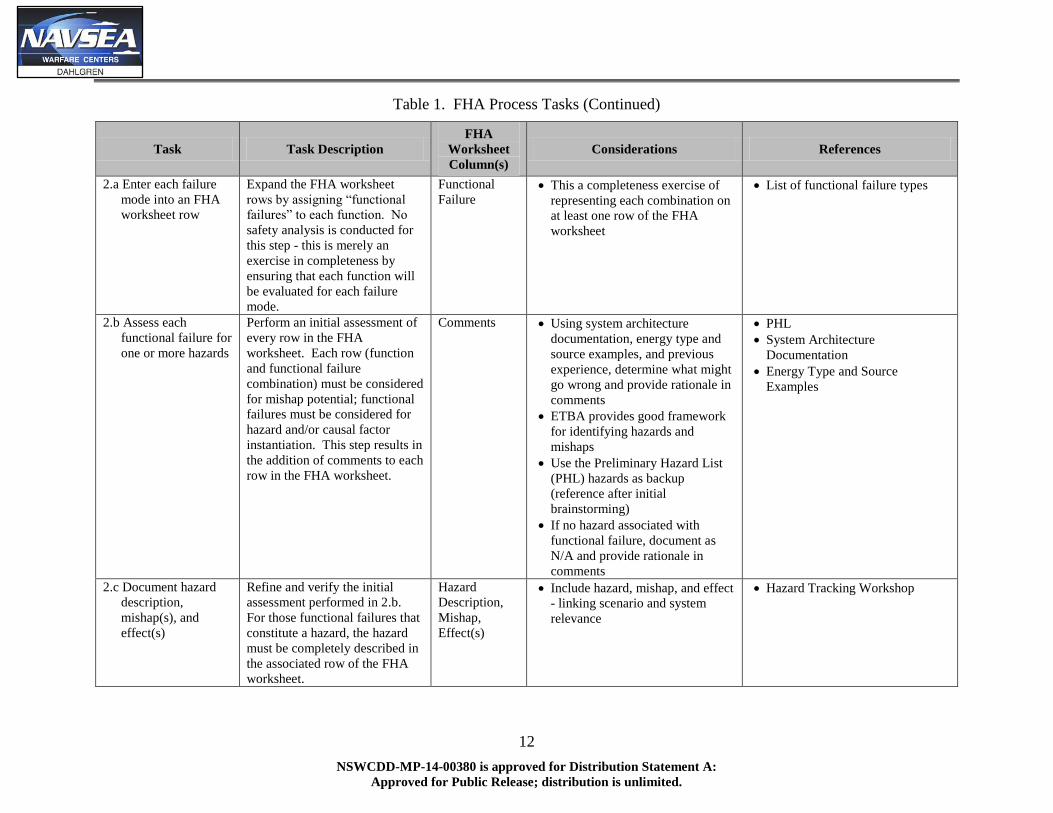
Table 1. FHA Process Tasks (Continued)
Task Task Description
FHA
Worksheet
Column(s)
Considerations References
2.a Enter each failure
mode into an FHA
worksheet row
Expand the FHA worksheet
rows by assigning “functional
failures” to each function. No
safety analysis is conducted for
this step - this is merely an
exercise in completeness by
ensuring that each function will
be evaluated for each failure
mode.
Functional
Failure This a completeness exercise of
representing each combination on
at least one row of the FHA
worksheet
List of functional failure types
2.b Assess each
functional failure for
one or more hazards
Perform an initial assessment of
every row in the FHA
worksheet. Each row (function
and functional failure
combination) must be considered
for mishap potential; functional
failures must be considered for
hazard and/or causal factor
instantiation. This step results in
the addition of comments to each
row in the FHA worksheet.
Comments Using system architecture
documentation, energy type and
source examples, and previous
experience, determine what might
go wrong and provide rationale in
comments
ETBA provides good framework
for identifying hazards and
mishaps
Use the Preliminary Hazard List
(PHL) hazards as backup
(reference after initial
brainstorming)
If no hazard associated with
functional failure, document as
N/A and provide rationale in
comments
PHL
System Architecture
Documentation
Energy Type and Source
Examples
2.c Document hazard
description,
mishap(s), and
effect(s)
Refine and verify the initial
assessment performed in 2.b.
For those functional failures that
constitute a hazard, the hazard
must be completely described in
the associated row of the FHA
worksheet.
Hazard
Description,
Mishap,
Effect(s)
Include hazard, mishap, and effect
- linking scenario and system
relevance
Hazard Tracking Workshop

13
NSWCDD-MP-14-00380 is approved for Distribution Statement A:
Approved for Public Release; distribution is unlimited.
Table 1. FHA Process Tasks (Continued)
Task Task Description
FHA
Worksheet
Column(s)
Considerations References
3. Identify safety-
significant
subsystems and
interfaces
Identify the subsystems and
interfaces that perform the SSFs.
The items allocated to an
identified hazard are identified
as SSIs.
System Item(s) System architecture
documentation (e.g., SV-5) should
provide function/item correlation
for SSI identification
Function/Item Matrix (e.g., SV-5)
4. Identify existing and
recommended
mitigations
Document questions that are
raised as a result of hazard
identification for follow-on
action. Recommend
requirements, design constraints,
warnings, and operator training
as able.
Existing
Mitigations,
Recommended
Mitigations
Mitigations should be considered
in terms of fault tolerance,
detection, isolation, annunciation,
or recovery
Existing mitigations may be
identified from system
architecture documentation or
system specification
This step should be performed
early on in system development to
allow for relatively cheap
implementation of recommended
mitigations
System Architecture
Documentation
System Specification
5. Decompose SSFs to
Components
N/A N/A

14
NSWCDD-MP-14-00380 is approved for Distribution Statement A:
Approved for Public Release; distribution is unlimited.
Table 1. FHA Process Tasks (Continued)
Task Task Description
FHA
Worksheet
Column(s)
Considerations References
5.a Evaluate
component-level
functional failures
Consider the failure mode of
each function in terms of
potential mishap(s) and effect(s)
- does the functional failure
constitute a hazard? Does the
functional failure constitute a
causal factor of a previously
identified hazard?
Hazard
Description,
Causal Factor
Description
Ensure that each function is
evaluated for all functional failure
modes (see detailed methodology
for descriptions)
System Architecture
Documentation
Failure Mode Reference List (see
below) -
1. Fails to operate
Function does not
happen/perform when given the
appropriate input
2. Operates at wrong time (early
or late)
Function performs earlier or later
than it should have; if too late
function could be out of sequence
3. Out of sequence
Function occurs in the incorrect
order; function occurs without
receiving the appropriate inputs
4. Failure to stop operation
Current function continues even
though it should move on to the
next function
5. Degraded function/malfunction
Function does not finish or only
partially completes (only some
outputs are provided); function
generates improper output
5.b Identify safety
significant
components and
interfaces
Utilize the updated SV-5 to
identify the components and
interfaces that perform the
subsystem SSFs.
System Item(s) System architecture
documentation (e.g., SV-5) should
provide function/item correlation
for SSI identification
Function/Item Matrix

15
NSWCDD-MP-14-00380 is approved for Distribution Statement A:
Approved for Public Release; distribution is unlimited.
Table 1. FHA Process Tasks (Continued)
Task Task Description
FHA
Worksheet
Column(s)
Considerations References
5.c Identify existing and
recommended
mitigations
Document questions that are
raised as a result of hazard
identification for follow-on
action. Recommend
requirements, design constraints,
warnings, and operator training
as able.
Existing
Mitigations,
Recommended
Mitigations,
Initial Mishap
Risk Index
(MRI), Target
MRI
Mitigations should be considered
in terms of fault tolerance,
detection, isolation, annunciation,
or recovery
Existing mitigations may be
identified from system
architecture documentation or
system specification
This step should be performed
early on in system development to
allow for relatively cheap
implementation of recommended
mitigations
System Architecture
Documentation
System Specification
6. Identify risk levels,
SwCIs, and follow-
on actions
Assess identified hazards for
mishap severity, mishap
probability of occurrence, and
software control category, as
appropriate; document questions
that are raised as a result of
hazard identification for follow-
on action.
Software
Control
Category,
Initial MRI,
SwCI, Target
MRI, Causal
Factor Risk
Level, Follow-
on Actions
Hardware- and human-related
hazards/causal factors must be
assessed in terms of mishap
severity and probability of
occurrence
Software-related hazards/causal
factors must be assessed in terms
of mishap severity and software
control category
Follow-on actions may consist of,
for example, detailed analyses to
be conducted during Subsystem
Hazard Analysis (SSHA) or LOR
verification tasks to be completed
on system software
Joint Software System Safety
Engineering Handbook
2014 International System Safety
Training Symposium (ISSTS)
Software Safety Tutorial

16
NSWCDD-MP-14-00380 is approved for Distribution Statement A:
Approved for Public Release; distribution is unlimited.
Table 1. FHA Process Tasks (Continued)
Task Task Description
FHA
Worksheet
Column(s)
Considerations References
7. Document Analysis Document the system
architecture and methodology
used for the analysis, as well as
the results, conclusions, and
recommendations generated
from the analysis. An initial
report must be provided for
PDR.
None Provide a system description in
terms of the physical and
functional characteristics of the
system, its subsystems, and the
components that make up those
subsystems
Ensure that the system
architecture documentation is
included or referenced in the FHA
report
Describe the methodology used
during conduct of the FHA and
summarize the results of the
analysis
MIL-STD-882E, Task 208

17
NSWCDD-MP-14-00380 is approved for Distribution Statement A:
Approved for Public Release; distribution is unlimited.
Table 2. FHA Worksheet
Hazard
ID #
Life-Cycle
PhaseActivity
State/
ModeFunction
Functional
FailureHazard Description System Item(s)
Causal Factor
DescriptionMishap Effect(s)
Identifier
used to
reference
specific
hazard
The life-cycle
phase for
which the
risk and risk
assessment
apply
The
actions
performed
within a
life-cycle
phase
The state
and/or
mode of
the system
for the
hazard of
concern
One of the
system
functions
(implicit,
implied, or
derived)
The detailed
description for
the specific
failure mode
of the
function
analyzed
The detailed
description of the
conditions under
which the hazardous
energy may be
release in an
uncontrolled or
inadvertent way
A functional or
physical portion of
a system designed,
used, or integrated
to accomplish one
aspect of the
system task or
mission
The detailed
description of the
failures,
conditions, or
events that
contribute either
directly or indirectly
to the existence of
a hazard
The event or
series of events
where hazardous
energy release
could negatively
effect equipment,
personnel, or
environment;
accident
The results of the
mishap to
include injury or
death, damage
to equipment
and property, or
damage to the
environment
Existing
Mitigations
Software Control
CategoryInitial MRI
Software Criticality
IndexTarget MRI
Causal Factor
Risk LevelRecommended Mitigations Comments Follow-On Actions
Controls
that are
already
planned or
existing to
mitigate the
risk
The degree of
autonomy,
command and
control authority,
and redundant
fault tolerance of a
software function
in context with its
system behavior
The first
assessment of the
potential risk of an
identified hazard
to establish a fixed
baseline for the
hazard. This may
have come from
the PHA
The level of
analysis rigor
required for risk
assessment
defined by the
software control
category and the
mishap severity of
the MRI
The projected risk the
PM plans to achieve by
implementing one or
more of the designated
recommended
mitigations. This field
should remain blank if
no recommended
mitigations are
identified
The projected
mishap risk level
associated with
the existence of
the specific
causal factor
and its potential
to realize the
hazard and
mishap
Controls that would reduce the
mishap risk potential. The goal
should always be to eliminate
the hazard if possible. When a
hazard cannot be eliminated,
the associated risk should be
reduced to the lowest
acceptable level by applying
the system safety design order
of precedence
Any
important
information
and relevant
information
not captured
elsewhere
Assigned or
designated
actions necessary
to identify or
better understand
or characterize
risk (e.g. perform
FTA, perform
software code
analysis)


![Gulf Coast Breeze. (Crawfordville, Florida) 1898-05-13 [p ].ufdcimages.uflib.ufl.edu/UF/00/07/59/04/00051/00380.pdfsentimental employer promised certainly perfectly ... whistle should](https://img.dokumen.tips/doc/110x75/5aef04f57f8b9abc788b7250/gulf-coast-breeze-crawfordville-florida-1898-05-13-p-employer-promised-certainly.jpg)