Embed Size (px)
Citation preview

www.animatics.com
DESCRIBES THE CLASS 5 AND 6 SMARTMOTOR™ SUPPORT FOR THE MODBUS® RTU PROTOCOL
CLASS 5 AND 6 SMARTMOTOR™ TECHNOLOGY
FULLY INTEGRATED SERVO MOTORS
MODBUS® RTU IMPLEMENTATION FOR
For the mobile version of this guide, see:animatics.com/docs/guides-html/c56_mbus_rtu/
Rev. D, March 2020

Copyright Notice©2014-2020, Moog Inc.
Moog Animatics Class 5 and 6 SmartMotor™ Modbus RTU Guide, Rev. D, PN: SC80100014-001.
This manual, as well as the software described in it, is furnished under license and may be used orcopied only in accordance with the terms of such license. The content of this manual is furnished forinformational use only, is subject to change without notice and should not be construed as acommitment by Moog Inc., Animatics. Moog Inc., Animatics assumes no responsibility or liability forany errors or inaccuracies that may appear herein.
Except as permitted by such license, no part of this publication may be reproduced, stored in aretrieval system or transmitted, in any form or by any means, electronic, mechanical, recording, orotherwise, without the prior written permission of Moog Inc., Animatics.
The programs and code samples in this manual are provided for example purposes only. It is theuser's responsibility to decide if a particular code sample or program applies to the application beingdeveloped and to adjust the values to fit that application.
Moog Animatics and the Moog Animatics logo, SmartMotor and the SmartMotor logo, Combitronic andthe Combitronic logo are all trademarks of Moog Inc., Animatics. Modbus is a registered trademark ofModbus Organization, Inc. Other trademarks are the property of their respective owners.
Please let us know if you find any errors or omissions in this manual so that we can improve it forfuture readers. Such notifications should contain the words "Modbus RTU Guide" in the subject lineand be sent by e-mail to: [email protected]. Thank you in advance for your contribution.
Contact Us:
Americas - WestMoog Animatics2581 Leghorn StreetMountain View, CA 94043USA
Americas - EastMoog Animatics1995 NC Hwy 141Murphy, NC 28906USA
Tel: 1 650-960-4215 Tel: 1 828-837-5115Fax: 1 540-557-6509
Support: 1 (888) 356-0357
Website: www.animatics.com
Email: [email protected]

Table Of Contents
Introduction 5Purpose 6
Safety Information 7
Safety Symbols 7
Other Safety Considerations 7
Motor Sizing 7
Environmental Considerations 7
Machine Safety 8
Documentation and Training 8
Additional Equipment and Considerations 9
Safety Information Resources 9
Additional Documents 10
Related Guides 10
Other Documents 10
Additional Resources 11
Modbus Resources 11
Motor Pinouts, Connections and Status LEDs 12Connecting the System (RTU) 13
Class 5 D-Style Motors: Connectors and Pinouts 13
Class 5 M-Style Motors: Connectors and Pinouts 14
Class 6 M-Style Motors: Connectors and Pinouts 15
Cable Diagram 16
Maximum Cable Length 16
Understanding the Status LEDs 17
Class 5 Motors 17
Class 6 Motors 18
Using Modbus 19Modbus RTU Description 20
OCHN Command 20
M-style Motor Example 20
D-style Motor Example 20
Legacy Modbus RTU Discussion 20
Supported Function Codes 21
16-Bit Access 21
Moog Animatics Class 5 and 6 SmartMotor™ Modbus RTU Guide, Rev. D
Page 3 of 32
32-Bit Access 21
Input Registers - 3X 22
3X Mapping 22
Holding Registers - 4X 23
4X Mapping 23
Modbus RTU Communications Example 24
Modbus RTU Communication Setup 24
Modbus RTU Sample Command Sequences 25
Read input registers (status word 3) 25
Write variable "a" (a=100000) 26
Read variable "a" (value returned is 100000) 27
Call GOSUB(1) (Success) 27
Troubleshooting 29
Moog Animatics Class 5 and 6 SmartMotor™ Modbus RTU Guide, Rev. D
Page 4 of 32
Introduction
IntroductionThis chapter provides information on the purpose and scope of this manual. It also providesinformation on safety notation, related documents and additional resources.
Purpose 6
Safety Information 7
Safety Symbols 7
Other Safety Considerations 7
Motor Sizing 7
Environmental Considerations 7
Machine Safety 8
Documentation and Training 8
Additional Equipment and Considerations 9
Safety Information Resources 9
Additional Documents 10
Related Guides 10
Other Documents 10
Additional Resources 11
Modbus Resources 11
Moog Animatics Class 5 and 6 SmartMotor™ Modbus RTU Guide, Rev. D
Page 5 of 32

Purpose
PurposeThis Modbus® guide describes the Modbus RTU protocol support provided by the Moog AnimaticsClass 5 and 6 SmartMotor™. It describes the major concepts that must be understood to integrate aSmartMotor slave with a PLC or other Modbus RTU (Remote Terminal Unit) master. However, it doesnot cover all the low-level details of the Modbus RTU protocol.
NOTE: The feature set described in this version of the manual refers to motor firmware 5.x.4.31 orhigher and 6.0.2.26 or higher.
This manual is intended for programmers or system developers who have read and understand theModbus Serial Line Protocol and Implementation Guide V1.02, which is published and maintained byModbus.org. Therefore, this manual is not a tutorial on that specification or the Modbus RTU protocol.Instead, it should be used to understand the specific implementation details for the Moog AnimaticsSmartMotor. For a general overview of Modbus RTU, see the FAQ page and other resources atwww.modbus.org.
Moog Animatics Class 5 and 6 SmartMotor™ Modbus RTU Guide, Rev. D
Page 6 of 32

Safety Information
Safety InformationThis section describes the safety symbols and other safety information.
Safety SymbolsThe manual may use one or more of the following safety symbols:
WARNING: This symbol indicates a potentially nonlethal mechanical hazard,where failure to follow the instructions could result in serious injury to theoperator or major damage to the equipment.
CAUTION: This symbol indicates a potentially minor hazard, where failure tofollow the instructions could result in slight injury to the operator or minor damageto the equipment.
NOTE: Notes are used to emphasize non-safety concepts or related information.
Other Safety ConsiderationsThe Moog Animatics SmartMotors are supplied as components that are intended for use in anautomated machine or system. As such, it is beyond the scope of this manual to attempt to cover allthe safety standards and considerations that are part of the overall machine/system design andmanufacturing safety. Therefore, the following information is intended to be used only as a generalguideline for the machine/system designer.
It is the responsibility of the machine/system designer to perform a thorough "Risk Assessment" andto ensure that the machine/system and its safeguards comply with the safety standards specified bythe governing authority (for example, ISO, OSHA, UL, etc.) for the locale where the machine is beinginstalled and operated. For more details, see Machine Safety on page 8.
Motor Sizing
It is the responsibility of the machine/system designer to select SmartMotors that are properly sizedfor the specific application. Undersized motors may: perform poorly, cause excessive downtime orcause unsafe operating conditions by not being able to handle the loads placed on them. The SystemBest Practices document, which is available on the Moog Animatics website, contains information andequations that can be used for selecting the appropriate motor for the application.
Replacement motors must have the same specifications and firmware version used in the approvedand validated system. Specification changes or firmware upgrades require the approval of the systemdesigner and may require another Risk Assessment.
Environmental Considerations
It is the responsibility of the machine/system designer to evaluate the intended operating environmentfor dust, high-humidity or presence of water (for example, a food-processing environment that requireswater or steam wash down of equipment), corrosives or chemicals that may come in contact with themachine, etc. Moog Animatics manufactures specialized IP-rated motors for operating in extremeconditions. For details, see the Moog Animatics Product Catalog.
Moog Animatics Class 5 and 6 SmartMotor™ Modbus RTU Guide, Rev. D
Page 7 of 32

Machine Safety
Machine Safety
In order to protect personnel from any safety hazards in the machine or system, the machine/systembuilder must perform a "Risk Assessment", which is often based on the ISO 13849 standard. Thedesign/implementation of barriers, emergency stop (E-stop) mechanisms and other safeguards will bedriven by the Risk Assessment and the safety standards specified by the governing authority (forexample, ISO, OSHA, UL, etc.) for the locale where the machine is being installed and operated. Themethodology and details of such an assessment are beyond the scope of this manual. However, thereare various sources of Risk Assessment information available in print and on the internet.
NOTE: The following list is an example of items that would be evaluated when performing the RiskAssessment. Additional items may be required. The safeguards must ensure the safety of allpersonnel who may come in contact with or be in the vicinity of the machine.
In general, the machine/system safeguards must:
l Provide a barrier to prevent unauthorized entry or access to the machine or system. The barriermust be designed so that personnel cannot reach into any identified danger zones.
l Position the control panel so that it is outside the barrier area but located for an unrestrictedview of the moving mechanism. The control panel must include an E-stop mechanism. Buttonsthat start the machine must be protected from accidental activation.
l Provide E-stop mechanisms located at the control panel and at other points around theperimeter of the barrier that will stop all machine movement when tripped.
l Provide appropriate sensors and interlocks on gates or other points of entry into the protectedzone that will stop all machine movement when tripped.
l Ensure that if a portable control/programming device is supplied (for example, a hand-heldoperator/programmer pendant), the device is equipped with an E-stop mechanism.
NOTE: A portable operation/programming device requires many additional system designconsiderations and safeguards beyond those listed in this section. For details, see thesafety standards specified by the governing authority (for example, ISO, OSHA, UL, etc.) forthe locale where the machine is being installed and operated.
l Prevent contact with moving mechanisms (for example, arms, gears, belts, pulleys, tooling, etc.).
l Prevent contact with a part that is thrown from the machine tooling or other part-handlingequipment.
l Prevent contact with any electrical, hydraulic, pneumatic, thermal, chemical or other hazardsthat may be present at the machine.
l Prevent unauthorized access to wiring and power-supply cabinets, electrical boxes, etc.
l Provide a proper control system, program logic and error checking to ensure the safety of allpersonnel and equipment (for example, to prevent a run-away condition). The control systemmust be designed so that it does not automatically restart the machine/system after a powerfailure.
l Prevent unauthorized access or changes to the control system or software.
Documentation and Training
It is the responsibility of the machine/system designer to provide documentation on safety, operation,maintenance and programming, along with training for all machine operators, maintenance technicians,programmers, and other personnel who may have access to the machine. This documentation mustinclude proper lockout/tagout procedures for maintenance and programming operations.
Moog Animatics Class 5 and 6 SmartMotor™ Modbus RTU Guide, Rev. D
Page 8 of 32

Additional Equipment and Considerations
It is the responsibility of the operating company to ensure that:
l All operators, maintenance technicians, programmers and other personnel are tested andqualified before acquiring access to the machine or system.
l The above personnel perform their assigned functions in a responsible and safe manner tocomply with the procedures in the supplied documentation and the company safety practices.
l The equipment is maintained as described in the documentation and training supplied by themachine/system designer.
Additional Equipment and Considerations
The Risk Assessment and the operating company's standard safety policies will dictate the need foradditional equipment. In general, it is the responsibility of the operating company to ensure that:
l Unauthorized access to the machine is prevented at all times.
l The personnel are supplied with the proper equipment for the environment and their jobfunctions, which may include: safety glasses, hearing protection, safety footwear, smocks oraprons, gloves, hard hats and other protective gear.
l The work area is equipped with proper safety equipment such as first aid equipment, firesuppression equipment, emergency eye wash and full-body wash stations, etc.
l There are no modifications made to the machine or system without proper engineeringevaluation for design, safety, reliability, etc., and a Risk Assessment.
Safety Information ResourcesAdditional SmartMotor safety information can be found on the Moog Animatics website; open the file"109_Controls, Warnings and Cautions.pdf" located at:
http://www.animatics.com/support/moog-animatics-catalog.html
OSHA standards information can be found at:
https://www.osha.gov/law-regs.html
ANSI-RIA robotic safety information can be found at:
http://www.robotics.org/robotic-content.cfm/Robotics/Safety-Compliance/id/23
UL standards information can be found at:
http://ulstandards.ul.com/standards-catalog/
ISO standards information can be found at:
http://www.iso.org/iso/home/standards.htm
EU standards information can be found at:
http://ec.europa.eu/growth/single-market/european-standards/harmonised-standards/index_en.htm
Moog Animatics Class 5 and 6 SmartMotor™ Modbus RTU Guide, Rev. D
Page 9 of 32

Additional Documents
Additional DocumentsThe Moog Animatics website contains additional documents that are related to the information in thismanual. Please refer to the following list.
Related Guidesl Class 5 SmartMotor™ Installation & Startup Guide
http://www.animatics.com/cl-5-install-startup-guide
l Class 6 SmartMotor™ Installation & Startup Guide
http://www.animatics.com/cl-6-install-startup-guide
l SmartMotor™ Developer's Guide
http://www.animatics.com/smartmotor-developers-guide
l SmartMotor™ System Best Practices
http://www.animatics.com/system-best-practices-application-note
Other Documentsl SmartMotor™ Product Certificate of Conformance
http://www.animatics.com/download/Declaration of Conformity.pdf
l SmartMotor™ UL Certification
http://www.animatics.com/download/MA_UL_online_listing.pdf
l SmartMotor Developer's Worksheet(interactive tools to assist developer: Scale Factor Calculator, Status Words, CAN Port Status,Serial Port Status, RMODE Decoder and Syntax Error Codes)
http://www.animatics.com/tools
l Moog Animatics Product Catalog
http://www.animatics.com/support/moog-animatics-catalog.html
Moog Animatics Class 5 and 6 SmartMotor™ Modbus RTU Guide, Rev. D
Page 10 of 32

Additional Resources
Additional ResourcesThe Moog Animatics website contains useful resources such as product information, documentation,product support and more. Please refer to the following addresses:
l General company information:
http://www.animatics.com
l Product information:
http://www.animatics.com/products.html
l Product support (Downloads, How To videos, Forums, Knowledge Base, and FAQs):
http://www.animatics.com/support.html
l Sales and distributor information:
http://www.animatics.com/sales-offices.html
l Application ideas (including videos and sample programs):
http://www.animatics.com/applications.html
Modbus ResourcesModbus is a common standard maintained by Modbus.org:
l Modbus.org website:
http://www.modbus.org
Moog Animatics Class 5 and 6 SmartMotor™ Modbus RTU Guide, Rev. D
Page 11 of 32

Motor Pinouts, Connections and Status LEDs
Motor Pinouts, Connections and Status LEDsThe following sections describe the motor pinouts, system connections and the status LEDs.
Connecting the System (RTU) 13
Class 5 D-Style Motors: Connectors and Pinouts 13
Class 5 M-Style Motors: Connectors and Pinouts 14
Class 6 M-Style Motors: Connectors and Pinouts 15
Cable Diagram 16
Maximum Cable Length 16
Understanding the Status LEDs 17
Class 5 Motors 17
Class 6 Motors 18
Moog Animatics Class 5 and 6 SmartMotor™ Modbus RTU Guide, Rev. D
Page 12 of 32
Connecting the System (RTU)
Connecting the System (RTU)The following sections show system connections and cable diagrams for typical Class 5 D-style andM-style motors and Class 6 M-style motors.
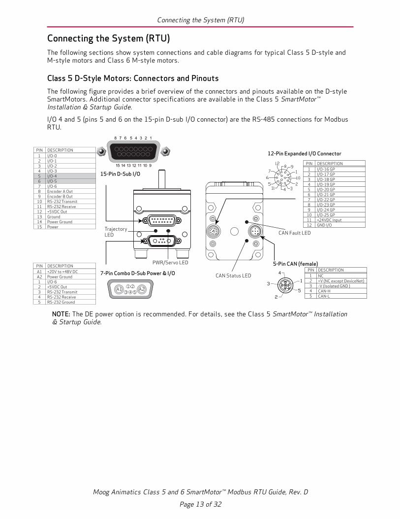
Class 5 D-Style Motors: Connectors and PinoutsThe following figure provides a brief overview of the connectors and pinouts available on the D-styleSmartMotors. Additional connector specifications are available in the Class 5 SmartMotor™Installation & Startup Guide.
I/O 4 and 5 (pins 5 and 6 on the 15-pin D-sub I/O connector) are the RS-485 connections for ModbusRTU.
PIN
12345
NC+V (NC except DeviceNet)-V (Isolated GND )CAN-HCAN-L
DESCRIPTION
5-Pin CAN (female)
123456789
101112
I/O-16 GPI/O-17 GPI/O-18 GPI/O-19 GPI/O-20 GPI/O-21 GPI/O-22 GPI/O-23 GPI/O-24 GPI/O-25 GP+24VDC InputGND I/O
PIN DESCRIPTION
12-Pin Expanded I/O Connector123456789
101112131415
I/O-0I/O-1I/O-2I/O-3I/O-4I/O-5I/O-6Encoder A OutEncoder B OutRS-232 TransmitRS-232 Receive+5VDC OutGroundPower GroundPower
PIN DESCRIPTION
7-Pin Combo D-Sub Power & I/O
A1 A21 2
3 4 5
A1A212345
+20V to +48V DCPower GroundI/O-6+5VDC OutRS-232 TransmitRS-232 ReceiveRS-232 Ground
PIN DESCRIPTION
15-Pin D-Sub I/O
Trajectory LED
PWR/Servo LED
CAN Fault LED
CAN Status LED
15 14 13 12 11 10 9
8 7 6 5 4 3 2 1
NOTE: The DE power option is recommended. For details, see the Class 5 SmartMotor™ Installation& Startup Guide.
Moog Animatics Class 5 and 6 SmartMotor™ Modbus RTU Guide, Rev. D
Page 13 of 32

Class 5 M-Style Motors: Connectors and Pinouts
Class 5 M-Style Motors: Connectors and PinoutsThe following figure provides a brief overview of the connectors and pinouts available on the M-styleSmartMotors. Additional connector specifications are available in the Class 5 SmartMotor™Installation & Startup Guide.
RS-485 channel 0 (pins 2 and 3 on the Communication connector) is the RS-485 connection forModbus.
PIN
12345
+24VDC OutI/O-3 or -LimitGND-CommonI/O-2 or +LimitI/O-10
DESCRIPTION
LIMIT INPUTS
PIN
12345
NC+V (NC except DeviceNet)-V (Unisolated Ground)CAN-HCAN-L
DESCRIPTION
CANOPEN
123456789
101112
I/O-0I/O-1I/O-4I/O-5I/O-6I/O-7I/O-8I/O-9Not Fault OutDrive Enable In+24VDC OutGND-Common
PIN
I/Os
12345678
GND-CommonRS-485B CH0RS-485A CH0ENC A+ (In/Out)ENC B- (In/Out)ENC A- (In/Out)+5VDC OutENC B+ (In/Out)
PIN DESCRIPTION
COMMUNICATION
1234
Control Power In 24VmaxChassis GND/EarthGND-CommonAmplifier Power 48Vmax
PIN DESCRIPTION
POWER INPUT
RS-485 serial communication uses a voltage differential signal. Appropriate terminating resistors should be included on the RS-485 network to ensure reliable performance.
DESCRIPTION
CANOPENRUN LED
12-Pin I/O
4-Pin Power Input
8-PinCOM Encoder Bus
5-Pin CANopen(female is standard)
5-PinLimit Inputs
CANOPENERROR LED
TRAJECTORYLED
SERVO-AMPLIFIERLED
Moog Animatics Class 5 and 6 SmartMotor™ Modbus RTU Guide, Rev. D
Page 14 of 32

Class 6 M-Style Motors: Connectors and Pinouts
Class 6 M-Style Motors: Connectors and PinoutsThe following figure provides a brief overview of the connectors and pinouts available on the Class 6M-style SmartMotors. Additional connector specifications are available in the Class 6SmartMotor™Installation & Startup Guide.
RS-485 channel 0 (pins 2 and 3 on the Communication connector) is the RS-485 connection forModbus.
1
2 3
4POWER INPUT
PIN FUNCTION DESCRIPTION
1 24 VDC CONTROL I/O POWER2 EARTH CHASSIS GROUND3 GND MOTOR COMMON GROUND4 48 VDC MOTOR POWER
COMMUNICATION
PIN FUNCTION
1 GND-COMMON2 RS-485B CH03 RS-485A CH04 ENC A+ (IN/OUT)5 ENC B- (IN/OUT)6 ENC A- (IN/OUT)7 5 VDC OUT8 ENC B+ (IN/OUT)
1
23
4
56
7
8
1
23
4
5
67
89
10
11
12
I/Os
PIN FUNCTION DEFAULT
1 IN0 GENERAL PURPOSE2 IN1 GENERAL PURPOSE3 IN2/POSLIMIT POSITIVE LIMIT4 IN3/NEGLIMIT NEGATIVE LIMIT5 IN4 GENERAL PURPOSE
6 IN5 GENERAL PURPOSE
7 IN6 GENERAL PURPOSE
8 IN7-DRVEN DRIVE ENABLE9 OUT8/BRAKE BRAKE OUTPUT
10 OUT9-NOFAULT NOT FAULT11 24 VDC OUT* CONTROL I/O POWER12 GND MOTOR COMMON GROUND
INPUT OR OUTPUT
INPUT, DISCRETE OR ANALOG
POSSIBLE (SELECTABLE) FUNCTIONS
INPUT, DISCRETE OR ANALOG INPUT INPUT INPUT
INPUT
INPUT
INPUT OUTPUT OUTPUT POWER OUTPUT** N/A
GENERAL PURPOSE GENERAL PURPOSE POSITIVE LIMIT OR GENERAL PURPOSE NEGATIVE LIMIT OR GENERAL PURPOSE GENERAL PURPOSE, OR EXTERNAL ENCODER INDEX CAPTURE GENERAL PURPOSE, OR INTERNAL ENCODER INDEX CAPTURE GENERAL PURPOSE, G COMMAND, OR HOMING INPUT (ETHERCAT ONLY)
N/A
NOT FAULT BRAKE OUTPUT OR GENERAL-PURPOSE OUTPUT DRIVE ENABLE
*NOTE: 2 AMPS MAX **SUPPLIED FROM POWER INPUT PIN 1
CONTROL I/O POWER
RS-485 serial communication uses a voltage differential signal. Appropriate terminating resistors should be included on the RS-485 network to ensure reliable performance. For details, see the sectionPower and RS-485 Com Multidrop.
1
2
3 4
Shield tied to motorhousing
LED 4: Link LED
LED 2: (Network specific**) LED
LED 0: Motor Drive LED
LED 5: Link LED
LED 3: (Network specific**) LED
LED 1: Motor Busy LED
*The Input/Output applies to these networks. Refer to the following CAUTIONS.**For LED Status information, refer to the corresponding SmartMotor fieldbus guide.
USB Port LEDSD Card LED
EtherNet/IP
PIN FUNCTION
1 +TX2 +RX3 -TX4 -RX
PIN FUNCTION
1 +TD2 +RD3 -TD4 -RD
PROFINET
*Input *Output
EtherCAT*
PIN FUNCTION
1 +TX2 +RX3 -TX4 -RX
Moog Animatics Class 5 and 6 SmartMotor™ Modbus RTU Guide, Rev. D
Page 15 of 32

Cable Diagram
Cable DiagramThe following figure shows a Modbus RTU master connected to a serial daisy chain of slave devices.Although different network topologies are possible, the daisy chain provides the most reliableperformance. If drops are made from the main trunk line, they should be kept as short as possible.
NOTE: When calculating the overall (total) cable length, you must account for all cable segments inthe network.
RS-485 Serial Bus
Other slave device:- I/O module,- etc.
Modbus Master*- PC,- PLC,- etc.
*Master may have termination option; see master’s documentation for details.
120 OhmTerminator
120 OhmTerminator*
SerialPort
Moog AnimaticsSmartMotor Slave
Moog AnimaticsSmartMotor Slave
SerialPort
SerialPort
SerialPort
NOTE: RS-485 serial communications uses a voltage differential signal that requires propertermination with a 120 ohm resistor at both ends of the network cable. This follows RS-485standards for biasing to ensure reliable performance.
Maximum Cable LengthNOTE: When calculating the overall (total) cable length, you must account for all cable segments inthe network.
Moog Animatics recommends a maximum cable length of 1000 meters or a maximum baud rate of115200. As baud rate increases, the maximum cable length decreases. The maximum cable lengthallowed depends on the baud rate, gauge and other physical properties of the cable, operatingenvironment and other factors.
For more details, see the Modbus Serial Line Protocol and Implementation Guide V1.02
Moog Animatics Class 5 and 6 SmartMotor™ Modbus RTU Guide, Rev. D
Page 16 of 32

Understanding the Status LEDs
Understanding the Status LEDsThis section describes the Modbus RTU status LEDs for the Class 5 and Class 6 motors.
Class 5 MotorsThe Status LEDs provide the same functionality for the D-style and M-style (including IP-sealed)SmartMotors.
NOTE: If the motor is equipped with the CANopen option, LEDs 2 and 3 do not apply to ModbusRTU.
LED Status on Power-up:• With no program and the travel limit inputs are low:
LED 0 will be solid red indicating the motor is in a fault state due to travel limit fault.
LED 1 will be off.
• With no program and the travel limit inputs are high:LED 0 will be solid red for 500 milliseconds and then begin flashing green.
LED 1 will be off.
• With a program that disables only travel limits and nothing else:
LED 0 will be solid red for 500 milliseconds and then begin flashing green.
LED 1 will be off.
LED 0: Drive Status Indicator
Off No power
Solid green Drive on
Flashing green Drive off
Flashing red Watchdog fault
Solid red Major fault
Alt. red/green In boot load; needs firmware
LED 1: Trajectory Status Indicator
Off Not busy
Solid green Drive on, trajectory in progress
P3 (CANopen option)
P1 (Power Input)
LED 0
P2 (COM Encoder Bus)
P3 (I/O Connector)
P4 (Limit Inputs)
P5 (CANopen)
LED 3LED 2
P4 (EXPANDED I/O option)
LED 1
LED 1
LED 2
LED 3
LED 0
P1 (Main Power)
P2 (I/O Connector)
Moog Animatics Class 5 and 6 SmartMotor™ Modbus RTU Guide, Rev. D
Page 17 of 32

Class 6 Motors
Class 6 MotorsThe following figure and tables describe the functionality of the Status LEDs on the Class 6SmartMotor.
Off No power
Solid green Drive on
Blinking green Drive off, no faults
Triple red flash Watchdog fault
Solid red Faulted or no drive enable input
Off Not busy Solid green Drive on, trajectory in progress
Flashing # red Flashes fault code* (see below) when Drive LED is solid red
Refer to the corresponding SmartMotor fieldbus guide
Refer to the corresponding SmartMotor fieldbus guide
Refer to the corresponding SmartMotor fieldbus guide
Refer to the corresponding SmartMotor fieldbus guide
LED 4: Link LED
LED 2: (Network specific) LED
LED 0: Motor Drive LED
LED 5: Link LED
LED 3: (Network specific) LED
LED 1: Motor Busy LED
LED 0: Motor Drive LED LED 1: Motor Busy LED
LED 3: (Network specific) LED
LED 5: Link LED
LED 2: (Network specific) LED
LED 4: Link LED
LED Status on Power-up:• With no program and the travel limit inputs are low:
LED 0 solid red; motor is in fault state due to travel limit fault
LED 1 off
• With no program and the travel limits are high:LED 0 solid red for 500 milliseconds then flashing green
LED 1 off
• With a program that only disables travel limits:
LED 0 red for 500 milliseconds then flashing green
LED 1 off
Flash123456789
1011
DescriptionNOT UsedBus VoltageOver CurrentExcessive TemperatureExcessive PositionVelocity LimitdE/Dt - First derivative of position error is excessiveHardware Positive Limit ReachedHardware Negative Limit ReachedSoftware Positive Travel Limit ReachedSoftware Negative Travel Limit Reached
LED 1 Fault Codes:
*Busy LED pauses for 2 seconds before flashing the code
Flickering = On/Off in 0.1 sec; Blinking = On/Off in 0.5 sec; Flashing = separated by 1 sec for EtherCAT LEDs and 2 sec for Fault Codes
Flashing green Active
Flashing red Suspended
Solid red USB power detected, no configuration
USB Active LED
Under cover: USB Active LEDSD Card LED (for SD Card-equipped motors)
Blinking green
Busy, do not remove card
Solid green
Card detected
Solid red
Card with no SmartMotor data
SD Card LED (for SD Card-equipped motors)No card, bad or damaged cardOff
Moog Animatics Class 5 and 6 SmartMotor™ Modbus RTU Guide, Rev. D
Page 18 of 32

Using Modbus
Using ModbusThe following sections describe how to enable Modbus communications with your SmartMotor, alongwith information on supported function codes, input registers and holding registers.
Modbus RTU Description 20
OCHN Command 20
M-style Motor Example 20
D-style Motor Example 20
Legacy Modbus RTU Discussion 20
Supported Function Codes 21
16-Bit Access 21
32-Bit Access 21
Input Registers - 3X 22
3X Mapping 22
Holding Registers - 4X 23
4X Mapping 23
Modbus RTU Communications Example 24
Modbus RTU Communication Setup 24
Modbus RTU Sample Command Sequences 25
Read input registers (status word 3) 25
Write variable "a" (a=100000) 26
Read variable "a" (value returned is 100000) 27
Call GOSUB(1) (Success) 27
Moog Animatics Class 5 and 6 SmartMotor™ Modbus RTU Guide, Rev. D
Page 19 of 32

Modbus RTU Description
Modbus RTU DescriptionModbus RTU is a standard that allows industrial devices to communicate over serial connections. TheMoog Animatics Class 5 and 6 SmartMotors support communication to a PLC, HMI, or other hostdevice over serial RS-485 only.
NOTE: The Moog Animatics Class 6 SmartMotor also supports the Modbus TCP/IP protocol overEthernet TCP/IP connections. Refer to that guide for details.
OCHN CommandThe OCHN command is used to open the serial port with Modbus RTU support. Refer to the followingexamples. By default, SmartMotor serial ports are not open in this mode.
The Class 5 and 6 SmartMotors will act as a slave devices in such a network. User integer variableshave read/write access as word (16-bit), or long (32-bit values). Status words can be read as 16-bitwords. Also, subroutines may be called via GOSUB(value).
NOTE: In this guide, hexadecimal numbers are prefixed by 0x. Therefore 0x0001 is a hexadecimalone in 16-bit representation, and 0x00000001 is a hexadecimal one in 32-bit representation.
M-style Motor ExampleOCHN(MB4,0,N,115200,1,8,D) ' Modbus Com0 M-series circular connector.
NOTE: Because the M-style SmartMotor has only one serial port, it is mutually exclusive withapplications that need to interact with the SMI software over serial communications. If the abovecode is used in an M-style motor, it may be necessary to use the SMI software CommunicationLockup Wizard to disable to program when SMI is needed to configure the motor.
D-style Motor ExampleOCHN(MB4,1,N,115200,1,8,D) ' Modbus Com1 D-series 15-pin connector.SADDR1 ' Modbus uses this address to identify itself.
For more details on the OCHN command, see the SmartMotor™ Developer's Guide.
Legacy Modbus RTU DiscussionMemory/registers designated as being in the 4X space are referred to as read/write space. This is anassociation consistent with legacy Modbus RTU.
Memory/registers designated as being in the 3X space are referred to as read-only space. This is anassociation consistent with legacy Modbus RTU.
For Class 5 and 6 SmartMotor access to resources described in this document, note that zero-basedaddressing is used. At the Modbus network level, this is the address that is transmitted. Somecontrollers may ask the user to specify addresses that are not zero-based. The address in the 4Xspace of 40001 is actually 0000(hex) on the network. Further, because legacy space is small, anetwork address of 8000(hex) is converted to a 4X reference as follows:
32768 + 40001 = 72769 (some Modbus RTU tools may do this)
Likewise, in the 3X space, the network address of 8000(hex) is converted to legacy format as follows:
32768 + 30001 = 62769
Note that address offsets are actually separated by function codes in the 4X and 3X legacy referencespaces. Therefore, what looks like an overlap in controller memory is not. The controller memory has
Moog Animatics Class 5 and 6 SmartMotor™ Modbus RTU Guide, Rev. D
Page 20 of 32
Supported Function Codes
been separated to respect the convention of read/write memory and read-only memory, 4X and 3X,respectively.
Some controllers may handle this differently. Therefore, it is the responsibility of the systemprogrammer to be aware of the method used in the host controller. The SmartMotor simply expectszero-based addresses and is not aware of any translation that the host may conduct.
Supported Function CodesA small set of Modbus function codes are supported for simple access to variables and status words.The GOSUB feature of the AniBasic language can be accessed through register write as well.
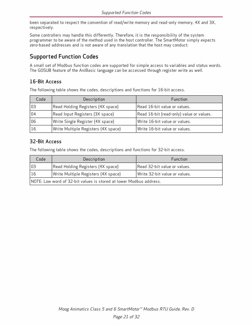
16-Bit AccessThe following table shows the codes, descriptions and functions for 16-bit access.
Code Description Function03 Read Holding Registers (4X space) Read 16-bit value or values.04 Read Input Registers (3X space) Read 16-bit (read-only) value or values.06 Write Single Register (4X space) Write 16-bit value or values.16 Write Multiple Registers (4X space) Write 16-bit value or values.
32-Bit AccessThe following table shows the codes, descriptions and functions for 32-bit access.
Code Description Function03 Read Holding Registers (4X space) Read 32-bit value or values.16 Write Multiple Registers (4X space) Write 32-bit value or values.NOTE: Low word of 32-bit values is stored at lower Modbus address.
Moog Animatics Class 5 and 6 SmartMotor™ Modbus RTU Guide, Rev. D
Page 21 of 32

Input Registers - 3X
Input Registers - 3XThe Modbus 3X input registers are 16-bit registers used to read data to the PLC (i.e., they are readonly). Regarding the SmartMotor, the set of data that can be read includes the Moog AnimaticsAniBasic "RW(x)" status words — the physical I/O state inputs RW(16) and, optionally, RW(17), andother RW(x) status words. Refer to the following table.
3X MappingThe following table describes the 3X mapping.
Address(hex)
Byte# Description Comments
0x0000 2 Status Register 0 Drive state and hardware limits0x0001 2 Status Register 1 Index capture and software limits0x0002 2 Status Register 2 Programs and communications0x0003 2 Status Register 3 PID and motion0x0004 2 Status Register 4 Timers0x0005 2 Status Register 5 Interrupts0x0006 2 Status Register 6 Commutation and bus0x0007 2 Status Register 7 Trajectory details0x0008 2 Status Register 8 Cam and interpolation user bits0x0009 2 Status Register 9 N/A0x000a 2 Status Register 10 N/A0x000b 2 Status Register 11 N/A0x000c 2 Status Register 12 User bits word 00x000d 2 Status Register 13 User bits word 10x000e 2 Status Register 14 N/A0x000f 2 Status Register 15 N/A0x0010 2 Status Register 16 I/O state, word 00x0011 2 Status Register 17 I/O state, word 1 (D-style with AD1 option only)
NOTES:1. Addresses shown are zero-based. Legacy Modbus addresses may be translated differently by thehost controller.2. Refer to the SmartMotor Developer's Guide for a full description of status word functionality.
LIMITATIONS: Up to 29 words can be read at a time (for the purposes of the input registers, reading is only meaningful up to the index shown in the previous table).
Moog Animatics Class 5 and 6 SmartMotor™ Modbus RTU Guide, Rev. D
Page 22 of 32

Holding Registers - 4X
Holding Registers - 4XThe Modbus 4X holding registers are 16-bit registers used to read data to and write data from thePLC. Regarding the SmartMotor, the set of data that can be read/written includes the Moog AnimaticsAniBasic variables a-zzz, ab, aw and al, and the GOSUB command. Refer to the following table.
4X MappingThe following table describes the 4X mapping.
Address (hex) Byte#
AniBasic CommandDescription Comments
0x2000-2033 - a to z User memory0x2034-2067 - aa to zz User memory0x2068-209B - aaa to zzz User memory, includes zzz0x209C-0x2101 ab[0]-ab[203]
al[0]-al[50]aw[0]-aw[101]
User memory array
0x8004 GOSUB(label) Execute subroutine specified by labelNOTES:
1. Addresses shown are zero-based. Legacy Modbus addresses may be translated differently by thehost controller.
2. User memory is word-addressable only. The low-addressed word is the lower half of a 32-bitnumber in the controller.
LIMITATIONS: Up to 29 words can be read at a time. However, if accessing SmartMotor variables a, b, c, etc., which are 2 words each as 32-bit variables, then 14 variables can be accessed in a read operation. Writing multiple registers has a restriction of up to 27 words (13 variables that are 32-bits each).
Moog Animatics Class 5 and 6 SmartMotor™ Modbus RTU Guide, Rev. D
Page 23 of 32

Modbus RTU Communications Example
Modbus RTU Communications ExampleThis topic contains Modbus communications examples.
Modbus RTU Communication SetupThis section describes a typical setup for Modbus RTU (serial) communications.
l Connect the SmartMotor's RS-485 pins to the PLC, HMI or other device that is serving as theModbus master. For details, refer to Connecting the System (RTU) on page 13.
l For D-style motors, I/O 4 and 5 (pins 5 and 6 on the 15-pin D-sub I/O connector) are theRS-485 connections for Modbus RTU.
l For M-style motors, RS-485 channel 0 (pins 2 and 3 on the Communication connector) isthe RS-485 connection for Modbus.
l Verify that the OCHN (Open Channel) command is in a user program in the connectedSmartMotor. For details, see OCHN Command on page 20.
l Verify that the SmartMotor's serial address is also used for the Modbus slave ID (i.e., both themotor address and Modbus slave ID must match). The SADDR= command is used in theprogram to set the SmartMotor serial address. Refer to the SADDR example in OCHN Commandon page 20.
l For testing, you can use a PC as the Modbus master along with the free utility programQModBus (http://qmodbus.sourceforge.net/). Refer to the following diagram.
4 3
2 1
Channel 0(pins 2 & 3)
M-Style SmartMotor (MODBUS Slave)
PC (MODBUS Master)
RS232485T
SEND
RECEIVE
CBLIP-COM-FL (8 Pin)
Modbus RTU Communication Test Example
Although this wouldn't be used for a real application, it allows you to communicate with aSmartMotor as the Modbus RTU slave. For examples, see Modbus RTU Sample CommandSequences on page 25.
Moog Animatics Class 5 and 6 SmartMotor™ Modbus RTU Guide, Rev. D
Page 24 of 32

Modbus RTU Sample Command Sequences
Modbus RTU Sample Command SequencesThis topic contains some sample Modbus RTU (serial) command sequences. These examples show thedata sent from and received by the Modbus master communicating with a SmartMotor. For theseexamples, a utility software, QModBus, is used to simulate the master, and the SmartMotor uses SlaveID 5.
For each of the following sections:
l Section title = action being performed
l SEND to motor = formatted byte stream sent from master to the SmartMotor
l RECV from motor = formatted byte stream received by the master from the SmartMotor
For each of the following tables:
NOTE: A table is provided to illustrate the parts of the byte sequence only. The byte sequencemust be transmitted as a stream of bytes shown in the SEND/RECEIVE strings above the table (i.e.,no pause or null for the blank cells).
l Slave ID = device node address
l Funct = function code (see Supported Function Codes on page 21)
l Start Addr = start address in memory or single register address (see Input Registers - 3X onpage 22 and Holding Registers - 4X on page 23)
l No. of Reg. = number of coils or number of registers
l Byte Cnt =byte count
l Data low word = data (low word)
l Data high word = data (high word)
l CRC = cyclic redundancy check
Read input registers (status word 3)NOTE: For information on input registers, see Input Registers - 3X on page 22.
SEND to motor: 05 04 00 03 00 01 C0 4E
RECV from motor: 05 04 02 30 90 5C 9C
SlaveID Funct Start
AddrNo. ofReg.
ByteCnt
Datalow word
Datahigh word CRC
SEND 05 04 00 03 00 01 C0 4ERECV 05 04 02 30 90 5C 9CA table is provided to illustrate the parts of the byte sequence only. The byte sequence must be transmitted as a stream ofbytes shown in the SEND/RECEIVE strings above the table (i.e., no pause or null for the blank cells).
Moog Animatics Class 5 and 6 SmartMotor™ Modbus RTU Guide, Rev. D
Page 25 of 32

Write variable "a" (a=100000)
QModBus Utility Showing SEND / RECEIVE Data
Write variable "a" (a=100000)SEND to motor: 05 10 20 00 00 02 04 86 A0 00 01 97 F4
RECV from motor: 05 10 20 00 00 02 4B 8C
SlaveID Funct Start
AddrNo. ofReg.
ByteCnt
Datalow word
Datahigh word CRC
SEND 05 10 20 00 00 02 04 86 A0 00 01 97 F4RECV 05 10 20 00 00 02 4B 8CA table is provided to illustrate the parts of the byte sequence only. The byte sequence must be transmitted as a stream ofbytes shown in the SEND/RECEIVE strings above the table (i.e., no pause or null for the blank cells).
QModBus Utility Showing SEND / RECEIVE Data
Moog Animatics Class 5 and 6 SmartMotor™ Modbus RTU Guide, Rev. D
Page 26 of 32

Read variable "a" (value returned is 100000)
Read variable "a" (value returned is 100000)SEND to motor: 05 03 20 00 00 02 CE 4F
RECV from motor: 05 03 04 86 A0 00 01 57 59
SlaveID Funct Start
AddrNo. ofReg.
ByteCnt
Datalow word
Datahigh word CRC
SEND 05 03 20 00 00 02 CE 4FRECV 05 03 04 86 A0 00 01 57 59A table is provided to illustrate the parts of the byte sequence only. The byte sequence must be transmitted as a stream ofbytes shown in the SEND/RECEIVE strings above the table (i.e., no pause or null for the blank cells).
QModBus Utility Showing SEND / RECEIVE Data
Call GOSUB(1) (Success)NOTE: If the program label doesn’t exist (it must be loaded as a user program in the motor), thenthe SmartMotor will return exception code 0x86 instead of the function code 0x06.
SEND to motor: 05 06 80 04 00 01 21 8F
RECV from motor: 05 06 80 04 00 01 21 8F
SlaveID Funct Start
AddrNo. ofReg.
ByteCnt
Datalow word
Datahigh word CRC
SEND 05 06 80 04 00 01 21 8FRECV 05 06 80 04 00 01 21 8FA table is provided to illustrate the parts of the byte sequence only. The byte sequence must be transmitted as a stream ofbytes shown in the SEND/RECEIVE strings above the table (i.e., no pause or null for the blank cells).
Moog Animatics Class 5 and 6 SmartMotor™ Modbus RTU Guide, Rev. D
Page 27 of 32

Call GOSUB(1) (Success)
QModBus Utility Showing SEND / RECEIVE Data
Moog Animatics Class 5 and 6 SmartMotor™ Modbus RTU Guide, Rev. D
Page 28 of 32

Troubleshooting
TroubleshootingThe following table provides troubleshooting information for solving common problems. For additionalsupport resources, see the Moog Animatics Support page at:
http://www.animatics.com/support.html
Issue Cause SolutionCommunication and Control IssuesMotor control powerlight does notilluminate.
Control power is off,disconnected orincorrectly wired.
Check that control power is connected to theproper pins and turned on. For connectiondetails, see Connecting the System (RTU) onpage 13.
Motor has routed drivepower through drive-enable pins.
Ensure cabling is correct and drive power isnot being delivered through the 15-pinconnector.
Motor is equipped withthe DE option.
To energize control power, apply 24-48 VDCto pin 15 and ground to pin 14.
Motor does notcommunicate with SMI.
Transmit, receive orground pins are notconnected correctly.
Ensure that transmit, receive and ground areall connected properly to the host PC.
Motor program is stuck ina continuous loop or isdisabling communications.
To prevent the program from running onpower up, use the Communications LockupWizard located on the SMI softwareCommunications menu.
Motor does notcommunicate withModbus RTU.
No OCHN command inprogram.
Verify that the OCHN command is used inprogram to set communication parameters.Modbus RTU does not have default settings.
Incorrect baud rate. Check the settings used for the OCHNcommand.
Incorrect Modbus RTUaddress.
Use SADDR or ADDR= command in programto set the correct address at startup.
Motor stopscommunicating afterpower reset, requiresre-detection.
Motor does not have itsaddress set in the userprogram. NOTE: Serialaddresses are lost whenmotor power is off orreset.
Use the SADDR or ADDR= command withinthe program to set the motor address.
Moog Animatics Class 5 and 6 SmartMotor™ Modbus RTU Guide, Rev. D
Page 29 of 32

Troubleshooting
Issue Cause SolutionMotor disconnects fromSMI sporadically.
COM port buffer settingsare too high.
Adjust the COM port buffer settings to theirlowest values.
Poor connection on serialcable.
Check the serial cable connections and/orreplace it.
Power supply unit (PSU)brownout.
PSU may be too high-precision and/orundersized for the application, which causesit to brown-out during motion. Make movesless aggressive, increase PSU size or changeto a linear unregulated power supply.
Red PWR SERVO lightilluminated.
Critical fault. To discover the source of the fault, use theMotor View tool located on the SMI softwareTools menu.
Common FaultsBus voltage fault. Bus voltage is either too
high or too low foroperation.
Check servo bus voltage. If motor uses theDE power option, ensure that both drive andcontrol power are connected.
Overcurrent occurred. Motor intermittently drewmore than its rated levelof current. Does not ceasemotion.
Consider making motion less abrupt withsofter tuning parameters or accelerationprofiles.
Excessive temperaturefault.
Motor has exceededtemperature limit of 85°C.Motor will remainunresponsive until it coolsdown below 80°C.
Motor may be undersized or ambienttemperature is too high. Consider adding heatsinks or forced air cooling to the system.
Excessive positionerror.
The motor's commandedposition and actualposition differ by morethan the user-suppliederror limit.
Increase error limit, decrease load or makemovement less aggressive.
Historicalpositive/negativehardware limit faults.
A limit switch wastripped in the past.
Clear errors with the ZS command.
Motor does not have limitswitches attached.
Configure the motor to be used without limitswitches by setting their inputs as generaluse.
Programming and SMI IssuesSeveral commands notrecognized duringcompiling.
Compiler default firmwareversion set incorrectly.
Use the Compiler default firmware versionoption in the SMI software Compile menu toselect a default firmware version closest tothe motor's firmware version. In the SMIsoftware, view the motor's firmware versionby right-clicking the motor and selectingProperties.
Moog Animatics Class 5 and 6 SmartMotor™ Modbus RTU Guide, Rev. D
Page 30 of 32

Troubleshooting
NOTES
Moog Animatics Class 5 and 6 SmartMotor™ Modbus RTU Guide, Rev. D
Page 31 of 32

www.animatics.com
For product information, visit www.animatics.com For more information or the office nearest you, contact us online, [email protected]
Moog is a registered trademark of Moog Inc. and its subsidiaries. All trademarks as indicated herein are the property of Moog Inc. and its subsidiaries.
TAKE A CLOSER LOOKMoog solutions for a wide variety of applications, including medical, office automation, packaging, industrial, aerospace and defense are only a click away. Visit our worldwide web site for more information.
Americas - West Americas - East Europe AsiaMoog Animatics Moog Animatics Moog Memmingen GmbH Moog Animatics2581 Leghorn Street 1995 NC Hwy 141 Allgaeustr. 8a Kichijoji Nagatani City Plaza 4FMountain View, CA94043 Murphy, NC 28906 87766 Memmingerberg 1-20-1, KichijojihonchoUnited States United States Germany Musashino-Shi, Tokyo 180-0004
Japan
Tel: +1 650-960-4215 Tel: +1 828-837-5115 Tel: +49 (0) 8331 98 480-0 Tel: +81 (0) 422 201251www.animatics.com www.animatics.com www.animatics.de www.animatics.jp
©2014-2020 Moog Inc. All rights reserved. All changes are reserved.
Moog Animatics Class 5 and 6 SmartMotor™ Modbus RTU Guide, Rev. DPN: SC80100014-001

![Developer's Guide for Class 5 or Later SmartMotor™ · 2021. 1. 6. · RAC 251 ACOS(value) 254 RACOS(value) 254 ADDR=formula 256 RADDR 256 ADT=formula 258 ADTS=formula 260 af[index]=formula](https://img.dokumen.tips/doc/110x75/60c91eecfac4d656786b50de/developers-guide-for-class-5-or-later-smartmotora-2021-1-6-rac-251-acosvalue.jpg)