Embed Size (px)
Citation preview

TM
Advanced Class 5 SmartMotor™ Features Include:
Class 5SmartMotor™ Technology
TMIntroducing high speed transparent communications over CAN bus.The optional Combitronic™ technology uses a CAN serial port to join all SmartMotor™ servos where any motor’s program can read, write or control any other motor simply by tagging a local variable or command with the other motor’s CAN address. All SmartMotor™
units become one multi-tasking, data-sharing system without writing a single line of communications code or requiring detailed knowledge of the CAN protocol.
This significant industry advancement allows any single axis to act as master to all other axes in the system, with each servo motor being capable of full access to and control of all motion parameters and I/O of all other servo motors. Any axis may trigger on inputs or
status registers in any other axis with sub-millisecond response time, exceeding the abilities of most PLCs to control motion and I/O together. Now all SmartMotor servos on the network may freely act upon system wide conditions for efficient process control of the entire machine design.
All Integrated Motor products made by Animatics are covered by patent number 5,912,541
Delivering significant industry advancements in programmable integrated servo systems
Phase Encoder
Signal
Derivative Error Limit used on Servo Controlled Spot Welder
Pre-defined Trapezoidal Gearing
SlaveGearedVelocity
SlewRatio
BitTrajectory
Bit
DescendBit
Master Encoder Input over time
Start
90
180
270
Phase Adjust ModeEnables applications such as product tracking where moves must be applied over a target in motion, automatically stabi-lizes pan & tilt applications, or allows arm end effectors to remain parallel to base while the mid arm section moves.
Derivative Error Limit (Rate of change of following error limit) This feature quickly detects jams for safer operation and less chance of damage to equipment or injury to machine operators.
Expanded Electronic Gearing FunctionalityNow includes separate Ascend, Slew and Descend pre-defined distances that may be defined off of either master or slave encoder values for enhancing applica-tions such as high speed winders.
Modulo Count ModeThis is especially useful in rotary pan or azimuth controls for targeting systems, radar, and camera bases. Combined with the Combitronic™ interface, multi camera surveillance systems may more easily pass off subject tracking from one pan & tilt to the next.
Phased Origin stays referenced to base allowing commanded moves to be DYNAMICALLY independent of the phase axis
PML= 360 (Position Modulo Limit) maintain counts between 0 and 359
PMT= 270 (Position Modulo Target) take shortest path to Target Position
Jaw stops immediately upon making contact with metal for minimal prod-uct deflection and maximum balance to each side
With an array of status bits available, all portions of the move may be used for I/O triggering.
Automatic transitions in and out are ideal for high speed labeling applica-tions
Class 5 Motion Profiles
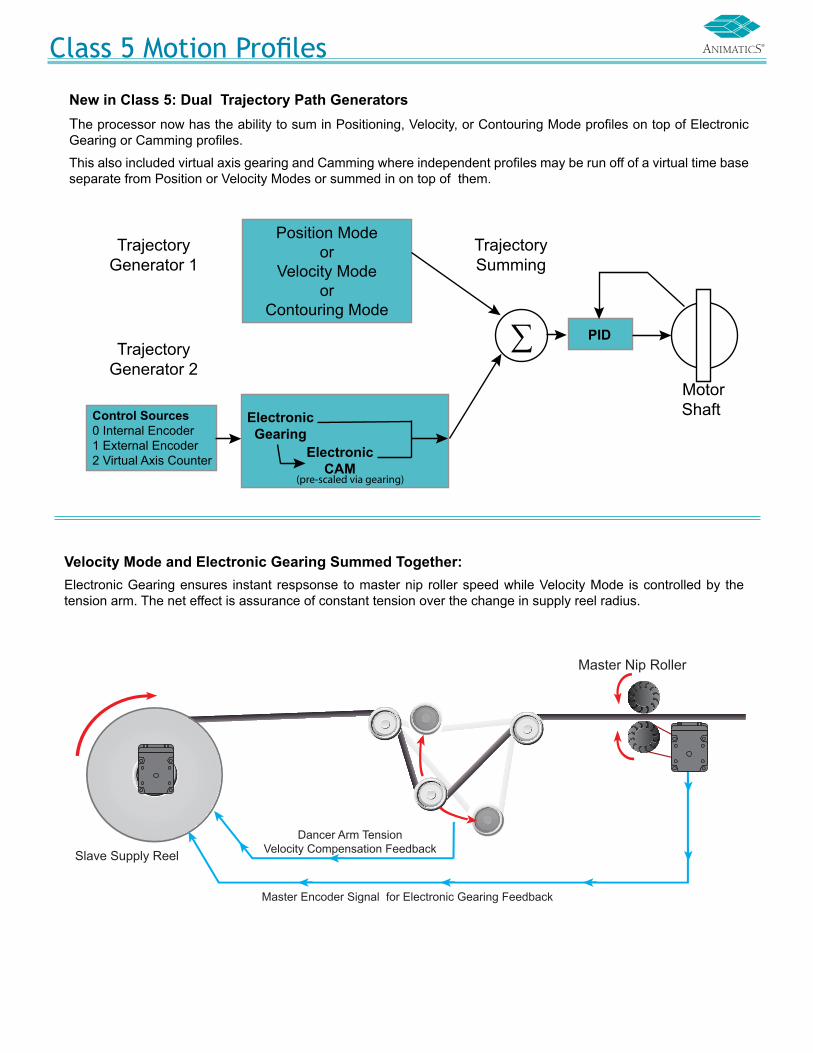
New in Class 5: Dual Trajectory Path Generators The processor now has the ability to sum in Positioning, Velocity, or Contouring Mode profiles on top of Electronic Gearing or Camming profiles.
This also included virtual axis gearing and Camming where independent profiles may be run off of a virtual time base separate from Position or Velocity Modes or summed in on top of them.
Position Modeor
Velocity Modeor
Contouring Mode
TrajectoryGenerator 1
TrajectoryGenerator 2
Control Sources0 Internal Encoder1 External Encoder2 Virtual Axis Counter
ElectronicGearing
ElectronicCAM
PID
TrajectorySumming
�∑ Motor Shaft
(pre-scaled via gearing)
Dancer Arm TensionVelocity Compensation Feedback
Master Nip Roller
Slave Supply Reel
Master Encoder Signal for Electronic Gearing Feedback
Velocity Mode and Electronic Gearing Summed Together:Electronic Gearing ensures instant respsonse to master nip roller speed while Velocity Mode is controlled by the tension arm. The net effect is assurance of constant tension over the change in supply reel radius.

TM
Combitronic operates over a standard “CAN” (Controller Area Network) interface but has no need of a dedicated master. Each Animatics SmartMotor™ connected to the same network communicates on an equal footing, sharing all information, and therefore, sharing all processing resources. An array of Animatics SmartMotor servos become one giant parallel-processing system when equipped with the Combitronic interface.
The only prerequisites for setting up Combitronic communications is to ensure each axis has a unique address and baud rates match.
Combitronic communications have further been architected to coexist invisibly with CANopen and DeviceNet protocols. This means that an array of SmartMotor™ servos can be set up as slaves to an external CANopen master, for example, and still be communicating with each other while the additional communications go undetected by the CANopen master without data collision.
The following code holds in a WHILE loop until the position of Motor 3 exceeds the position of Motor 4.
WHILEPA:3<PA:4LOOP 'WaitforMotor3topassMotor4
As can be seen, any single Animatics servo can now actively grab dynamic data from one or more servos on the network as needed, without the need for code residing in the other SmartMotor servos. The IF conditon below stops motion if Motor 5 slows down.
IFVA:5<10000 'IfrealtimespeedinMotor5dropsbelow100000 X 'stopmotioninthismotor ENDIF
Communications
RS-232
CombitronicMaster
CombitronicMaster
CombitronicMaster
CombitronicMaster
Bank 1 Bank 2 Bank 3 Bank 4
CombitronicSlave
CombitronicSlave
CombitronicSlave
CombitronicSlave
CombitronicSlave
CombitronicSlave
CombitronicSlave
CombitronicSlave
ControllingPC
RX
TX
Motor 2 Motor 2 Motor 2 Motor 2
Motor 3 Motor 3 Motor 3 Motor 3
TX RX TX RX TX RX TX RX
This configuration bypasses the need for a host CAN bus device or CAN bus interface for a PC, allowing standard RS-232 ASCII to control multiple motors. Combitronic technology allows pass-through communications between RS-232 and CAN bus.
Combitronic™ with RS-232 Interface
2PT:3=1234 'setBank2Motor3targetpositon30:0=0 'setorigintozeroonallBank3motors1RPA:2 'reportBank1Motor2actualposition0G 'SendGocommandtoRS232motorsonly2G:0 'SendGocommandtoallBank2motors0G:0 'SendGocommandtoallmotorsonall
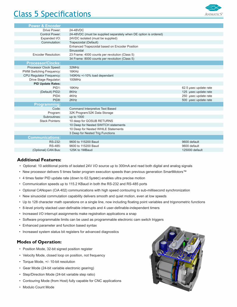
Class 5 SpecificationsPower & Encoder
Drive Power: 24-48VDCControl Power: 24-48VDC (must be supplied separately when DE option is ordered)Expanded I/O: 24VDC isolated (must be supplied)Commutation: Trapezoidal (Default)
Enhanced Trapezoidal based on Encoder PositionSinusoidal
Encoder Resolution: 23 Frame: 4000 counts per revolution (Class 5)34 Frame: 8000 counts per revolution (Class 5)
Processor/Clocks:Processor Clock Speed: 32MHz
PWM Switching Frequency: 16KHzCPU Regulator Frequency: 140KHz +/-10% load dependant
Drive Stage Regulator: 100MHzPID Update Rates:
PID1: 16KHz 62.5 μsec update rate(Default) PID2: 8KHz 125 μsec update rate
PID4: 4KHz 250 μsec update ratePID8: 2KHz 500 μsec update rate
Programming:Code: Command Interpretive Text Based
Program: 32K Program/32K Data StorageSubroutines: up to 1000
Stack Pointers: 10 deep for GOSUB RETURNS10 Deep for Nested SWITCH statements10 Deep for Nested WHILE Statements3 Deep for Nested Trig Functions
Communications:RS-232: 9600 to 115200 Baud 9600 defaultRS-485: 9600 to 115200 Baud 9600 default
(Optional) CAN Bus: 125K to 1MBaud 125000 default
• Optional: 10 additional points of isolated 24V I/O source up to 300mA and read both digital and analog signals
• New processor delivers 5 times faster program execution speeds than previous generation SmartMotors™
• 4 times faster PID update rate (down to 62.5μsec) enables ultra precise motion
• Communication speeds up to 115.2 KBaud in both the RS-232 and RS-485 ports
• Optional CANopen (CiA 402) communications with high speed contouring to sub-millisecond synchronization
• New sinusoidal commutation capability delivers smooth and quiet motion, even at low speeds
• Up to 128 character math operations on a single line, now including floating point variables and trigonometric functions
• 8-level priority stacked user-definable interrupts and 4 user-definable-independent timers
• Increased I/O interrupt assignments make registration applications a snap
• Software programmable limits can be used as programmable electronic cam switch triggers
• Enhanced parameter and function based syntax
• Increased system status bit registers for advanced diagnostics
• Position Mode, 32-bit signed position register
• Velocity Mode, closed loop on position, not frequency
• Torque Mode, +/- 10-bit resolution
• Gear Mode (24-bit variable electronic gearing)
• Step/Direction Mode (24-bit variable step ratio)
• Contouring Mode (from Host) fully capable for CNC applications
• Modulo Count Mode
Additional Features:
Modes of Operation:

PIN MAIN POWER Specifications: P11 I/O – 6 GP or “G” command 25mAmp sink or source
10Bit 0-5VDC A/DRedundant connection on I/O connector 7W2 Combo
D-sub Connector2 +5VDC out 50mAmps max (total)3 RS-232 Transmit Channel(0) 115.2KBaud max4 RS-232 Receive Channel(0) 115.2KBaud max5 SIG GroundA1 Main Power: +20-48VDCA2 GroundPIN I/O CONNECTOR (5VTTL I/O) Specifications: P21 I/O – 0 GP or enc. A or step input 25mAmp sink or source
10Bit 0-5VDC A/D1.5MHz max as enc or step input
DB-15 D-sub Connector
2 I/O – 1 GP or enc. B or dir. input 25mAmp sink or source10Bit 0-5VDC A/D
1.5MHz max as enc or dir. input
3 I/O – 2 Positive over travel or GP 25mAmp sink or source10Bit 0-5VDC A/D
4 I/O – 3 Negative over travel or GP 25mAmp sink or source10Bit 0-5VDC A/D
5 I/O – 4 GP or RS-485 A Channel(1) 25mAmp sink or source10Bit 0-5VDC A/D
115.2KBaud max
6 I/O – 5 GP or RS-485 B Channel(1) 25mAmp sink or source10Bit 0-5VDC A/D
115.2KBaud max
7 I/O – 6 GP or “G” command 25mAmp sink or source10Bit 0-5VDC A/D
Redundant connection on Main Power Connector
8 Phase A encoder output9 Phase B encoder output10 RS-232 Transmit Channel(0) 115.2KBaud max11 RS-232 Receive Channel(0) 115.2KBaud max12 +5VDC out 50mAmps max (total)13 SIG Ground14 Ground15 Main Power: +20-48VDC If -DE option, control power
separate from main powerPIN CAN-bus Connection: P31 NC NC M12 5-PIN
FEMALE END VIEW2 NC NC3 GND_CAN Isolated CAN ground4 CAN-H 1M Baud max5 CAN-L 1M Baud max
PIN Isolated 24VDC I/O Connector Max Load (sourcing) P41 IO – 16 GP 150mAmps
M12 12-PIN FEMALE END VIEW
2 IO – 17 GP 150mAmps3 IO – 18 GP 150mAmps4 IO – 19 GP 150mAmps5 IO – 20 GP 300mAmps 6 IO – 21 GP 300mAmps7 IO – 22 GP 300mAmps8 IO – 23 GP 300mAmps9 IO – 24 GP 300mAmps10 IO – 25 GP 300mAmps11 +24Volts input 18-32VDC12 GND-I/O
Class 5 Connector Pinouts
15 14 13 12 11 10 9
11 10 9
A1 A21 23 4 5
8 7 6 5 4 3 2 1
15 14 13 12 11 10 9
11 10 9
A1 A21 23 4 5
8 7 6 5 4 3 2 1

NEMA 17 FRAMEBRAKE 24V I/O CAN bus
NEMA 34 FRAMEBRAKE 24V I/O CAN bus
-BRK -AD1 -C or -DN -BRK -AD1 -C or -DN
SM17205D
●
SM34165D**SM34165DT**SM34105DSM34205DSM34305DSM34405D
● ● ● ● ● ● ●● ●
● ● ● ● ● ● ●
NEMA 23 FRAMEBRAKE 24V I/O CAN bus -BRK -AD1 -C or -DN
SM23165DSM23165DT
● ●
● ● ●
SM23375DSM23375DTSM23105DSM23205DSM23305DSM23405D
● ●● ●
●● ● ● ● ● ● ●
Animatics Class 5 SmartMotor™ Part Numbering Guidelines
17 20
101620
303740
DD-Sub
DTD-Sub
High Torque
Frame Size Motor ConnectorStyle
34
23
Class 5
1623
NEMA Frame
NEMA Frame
NEMA Frame
101620
304050
Options
Internal brake
Drive enable*
Internal shunt(select models only)**SH
24V Expansion I/O
Options
CANopen™ option
DeviceNet™
1 Flat on shaft
2 Flats on shaft
Complete sealed optionReduced shaft lengthSealed without shaft seal
Machined keywayon motor shaft-K
Profibus-PB ®^
For an overview
of all our products, visit:
www.animatics.com
Animatics Class 5 SmartMotor™ Available Option Combinations
Copyright 2010 by Animatics Corporation. All rights reserved.
**SM34165D & SM34165DT are the only models that can have an internal shunt.
Animatics Corporation • 3200 Patrick Henry Drive, Santa Clara, CA, 95054 • tel: 408.748.8721 • fax: 408.748.8725 • www.animatics.com
FBCL5-1010
* Separate drive & control power^ Profibus option only available on SM23165D & SM23165DT products and without brake or 24V I/O** SM34165D & SM34165DT are the only models that can have an internal shunt.


![Developer's Guide for Class 5 or Later SmartMotor™ · 2021. 1. 6. · RAC 251 ACOS(value) 254 RACOS(value) 254 ADDR=formula 256 RADDR 256 ADT=formula 258 ADTS=formula 260 af[index]=formula](https://img.dokumen.tips/doc/110x75/60c91eecfac4d656786b50de/developers-guide-for-class-5-or-later-smartmotora-2021-1-6-rac-251-acosvalue.jpg)