Embed Size (px)
Citation preview

52 APRIL 2003 / Concrete international
BY NABIL F. GRACE, GEORGE ABDEL-SAYED, FREDERICK C. NAVARRE,RICHARD B. NACEY, WAYNE BONUS, AND LORIS COLLAVINO
Currently, advanced fiber-reinforced polymer (FRP)materials find worldwide application in the construction
of small and large structures,1-5 such as beams andbridges. However, there are few prestressed concretebridges constructed using carbon fiber-reinforcedpolymer (CFRP) tendons as the only flexural reinforce-ment.1-6 FRP is a linearly elastic material, which may notprovide a ductile failure mode if substituted directly forsteel. Results of early research investigations6-10 con-ducted at the Structural Testing Center of LawrenceTechnological University, Southfield, MI, have shownthat internally bonded CFRP tendons, in combinationwith externally draped unbonded CFRP tendons, canlead to reasonably ductile systems for simply sup-ported6,7 and continuous8,10 prestressed concrete bridges.We based both the design of the Bridge Street Bridge11
(located in the city of Southfield, MI) and the double-tee(DT) test beam14 used in this study on these results. TheBridge Street Bridge is the most recent CFRP prestressedconcrete bridge in the U.S., and the first to use CFRPLeadline* tendons, carbon fiber composite cable (CFCC)†
strands, and CFRP NEFMAC‡ sheets.Due to the lack of existing design standards for FRP
prestressed concrete bridges, the Bridge Street Bridgedesign and research team decided to validate the designand construction approach they had developed bytesting a full-scale DT beam14 to failure prior to proceedingwith the manufacture of the 12 DT beams to be used inthe bridge itself. This article presents the experimentalinvestigation of the DT test beam (identical to those usedin the Bridge Street Bridge 11) to evaluate the design and
Full-Scale Test ofPrestressed
Double-Tee BeamCarbon fiber-reinforced polymer provides reinforcement for new bridge design
construction procedures used, along with critical majorstructural parameters such as concrete strains, deflec-tions, forces in the post-tensioning strands at the serviceload, cracking load, ultimate load, and the type andpattern of failure experienced at the ultimate load.
FABRICATION AND INSTRUMENTATIONFigure 1 shows the cross section of the DT test
beam. Reinforcement for each web of the DT beamconsisted of 10 rows of 10-mm-diameter bondedprestressed CFRP tendons and six rows of 12.5 mmnonprestressed CFCC strands. The cross section of theDT beam contains four externally draped, 40-mm-diameter post-tensioned CFCC strands between thewebs and 19 10-mm-diameter nonprestressed CFRP rodsin the flange. In addition, the flange also contains twolayers of transverse, 10-mm-diameter CFRP rods. ACFRP sheet located in the composite concrete toppingprovides reinforcement to control temperature andshrinkage cracks. Table 1 gives the mechanical charac-teristics of the CFRP tendons/rods and the CFCCstrands, while Table 2 and 3 present the characteristicsof the CFRP sheets and the concrete, respectively.12, 13
*Trademark name of CFRP Leadline tendons provided by Mitsubishi
Chemical Corp., Japan†Trademark name of CFCC strands provided by Tokyo Rope Mfg. Co.,
Ltd., Japan‡Trademark name of CFRP grids provided by Autocon Composites
Inc., Canada

Concrete international / APRIL 2003 53
FabricationA single pan form consisting of
two stems, the top flange, and seventransverse integral diaphragms (D1to D7) was used to fabricate theDT test beam. All diaphragmformwork required special attentionto eliminate any constraints orconcrete cracking (between thestems and diaphragms) due toelastic shortening resulting from thetendon release. All constructionactivities took place at the precastfabricator’s plant using a concretemixture that developed a cylinderstrength of 53.8 MPa at the time thebeam was tested. The followingparagraph outlines the sequence ofconstruction activities.
Installation of the CFCC and CFRPflexural reinforcement, steel stirrups,CFRP prestressing tendons, and otherembedded items in the formwork(Fig. 2) marked the initial fabricationstage. Nine of the ten rows of CFRPtendons were draped beforepretensioning using the “hold-down”
Fig. 1: Midspan cross section of the DT test beam for the Bridge Street Bridge project
TABLE 1:MECHANICAL CHARACTERISTICS AND MATERIAL PROPERTIES OF THE CFRP TENDONSAND THE CFCC STRANDS USED IN THE BRIDGE STREET BRIDGE PROJECT AND THEDT TEST BEAM
TABLE 2:MECHANICAL CHARACTERISTICS AND MATERIAL PROPERTIES OF THE NEFMAC SHEETSUSED IN THE BRIDGE STREET BRIDGE PROJECT AND THE DT TEST BEAM
TABLE 3:MATERIAL PROPERTIES OF THE PRECAST CONCRETE AND CONCRETE TOPPING USED FOR THEBRIDGE STREET BRIDGE PROJECT AND THE DT TEST BEAM

54 APRIL 2003 / Concrete international
and the “hold-up” rollers that kept the tendons in placeduring concrete placement, while the bottom-most rowof CFRP tendons was kept straight (Fig. 3). Each CFRPtendon was individually pretensioned to target loadlevels (after seating losses) of 82 kN for rows 1 to 5 (rownumbering starts from the top to the bottom) and 87 kNfor rows 6 to 10. The concrete was placed in theformwork and allowed to cure. After the concreteachieved sufficient strength (45.9 kN), the CFRP tendonswere released and the prestressed beam was removedfrom the formwork. Finally, the four externally drapedpost-tensioning CFCC strands were installed, and, usingthe manufacturer’s built-in anchor system, 60% of thefinal post-tensioning force (445 kN) was applied to eachstrand prior to transport to the testing facility (Fig. 4).
InstrumentationMeasurement of pretensioning force: A load cell was
installed between the fabricator’s stressing jack at thelive end and the anchorage (chuck) and was used tomeasure the pretensioning forces with a read-out device.Also, a few load cells were positioned at the dead end ofselected tendons (between the anchor head and thebulkhead) to verify readings taken at the live end. Wealso used the elongation of the tendons and the pressuregage of the hydraulic pump to verify the desiredpretensioning forces. Once the jacking force gagepressure and elongation were recorded, the stressingassembly was transferred to the next tendon. Thisprocedure continued until all 60 CFRP tendons werestressed. Technicians continuously monitored the loadcells located at the dead end during and after theconcrete placement to measure any changes in thepretensioning forces. Further details can be found inReference 14.
Measurement of concrete strain: Strain gages wereembedded in the concrete to measure strain distribu-tions along the depth of the cross sections at midspanand at the quarter spans. Of the 30 gages installed in thetest beam, 21 gages were installed in the precast sectionat the fabrication plant, while the remaining nine gageswere installed in the cast-in-place concrete topping atthe testing facility. Moreover, seven, vibrating-wire straingages (Fig. 5) were also installed in each of the twowebs at opposite ends of the beam for transfer lengthmeasurements. The transfer length9,14 (according to ACI116R-90) is “the length from the end of the memberwhere the tendon stress is zero to the point along thetendon where the prestress is fully effective.”
Measurement of post-tensioning forces: Before post-tensioning, all four post-tensioning strands were instru-mented with load cells at one end. The load cells wereinstalled between the lock nut on the strand anchor andthe bearing plate embedded in the transverse diaphragm(D2) near the end of the beam. Initial load cell readings
Fig. 2: The initial fabrication stage of the DT test beam includedinstallation of the CFCC and CFRP reinforcement, the steelstirrups, and other embedded items in the formwork
Fig. 3: Installation and stressing of the pretensioned CFRPtendons in the DT test beam
Fig. 4: Applying 60% of the total post-tensioning force to thelongitudinal CFCC strands

Concrete international / APRIL 2003 55
were documented just before stressing the strands toserve as a reference for all subsequent readings.
Post-tensioning forces were applied to the four CFCCstrands in the two separate stages (initial and final).Initial post-tensioning, conducted at the precast plant,applied 60% of the total desired post-tensioning force(445 kN). The final post-tensioning force was applied atthe testing facility after casting the 75-mm-thick concretetopping to bring the post-tensioning to 100% of the totaldesired force.
Each stage (initial and final) of post-tensioning wasapplied in two increments. During the first increment,approximately 50% (134 kN) of the initial post-tensioningforce (30% of the total desired force) was applied bypulling the strands from one end. The post-tensioningsetup was then moved to the opposite end to apply theremaining 30% of the total desired force. The test beamwas supported at the D2 and D6 intermediate transversediaphragms throughout the initial post-tensioningoperations and until its transport to the testing facility.Figure 6 shows the transportation of the precast DT testbeam from the manufacturer’s precast yard in Windsor,ON, to the testing facility in Chicago, IL. Final post-tensioning was applied at the test facility with the beamsupported at the end diaphragms (D1 and D7) afterthe placement of the concrete topping. The averagemeasured strand force after the initial post-tensioningwas 268 kN, while the average measured strand forceafter the final post-tensioning was 449 kN. A similarincremental approach was used to apply the final targetforce (the remaining 40% of the total post-tensioningforce) before the start of testing. The average measuredforce in the CFCC tendons just prior to testing was 443 kN.
TEST SETUPAs shown in Fig. 7, the DT test beam had a span length
of 20.4 m and was simply supported at both ends usingroller supports. The test beam was loaded along twolines orthogonal to its longitudinal centerline to create a3658-mm-wide constant moment region symmetricalabout its midspan. Along each line, load was applied attwo bearing points that were coincident with the beam’swebs. Load was applied using a series of hydraulic jackswith load and extension capability sufficient to induceflexural failure. All loads applied to the beam during thetest were monitored using load cells. Beam displacementsat midspan and quarter span locations were monitoredusing two displacement transducers at each locationattached to the underside of the two webs. In addition tothe applied loads and deflections, output from theconcrete strain gages installed for measuring straindistribution at midspan and the two quarter-spansections, and from the longitudinal CFCC strand loadcells, was also monitored during the flexural test. Output14
from instrumentation was monitored throughout the test
Fig. 5: Seven vibrating-wire strain gages at each of the two websof the DT test beam for transfer length measurement
Fig. 6: Transportation/barging of DT test beam across the DetroitRiver as it traveled from the manufacturer’s precast yard(Windsor, ON) to the testing facility (Chicago, IL)
Fig. 7: The test beam was loaded along two lines orthogonal toits longitudinal centerline to create a constant moment regionsymmetrical about the beam’s midspan
56 APRIL 2003 / Concrete international
Fig. 8: The distribution of concrete strains along the depth of the test beam’s cross section after final post-tensioning. Strains areshown at the beam’s midspan and two quarter span locations
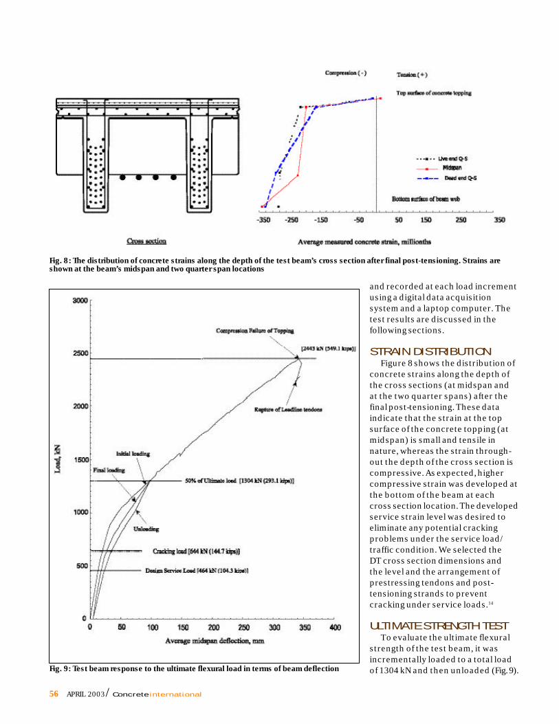
Fig. 9: Test beam response to the ultimate flexural load in terms of beam deflection
and recorded at each load incrementusing a digital data acquisitionsystem and a laptop computer. Thetest results are discussed in thefollowing sections.
STRAIN DISTRIBUTIONFigure 8 shows the distribution of
concrete strains along the depth ofthe cross sections (at midspan andat the two quarter spans) after thefinal post-tensioning. These dataindicate that the strain at the topsurface of the concrete topping (atmidspan) is small and tensile innature, whereas the strain through-out the depth of the cross section iscompressive. As expected, highercompressive strain was developed atthe bottom of the beam at eachcross section location. The developedservice strain level was desired toeliminate any potential crackingproblems under the service load/traffic condition. We selected theDT cross section dimensions andthe level and the arrangement ofprestressing tendons and post-tensioning strands to preventcracking under service loads.14
ULTIMATE STRENGTH TESTTo evaluate the ultimate flexural
strength of the test beam, it wasincrementally loaded to a total loadof 1304 kN and then unloaded (Fig. 9).

Concrete international / APRIL 2003 57
We planned this loading and unloading sequence toevaluate the inelastic energy absorbed in the system andto predict the associated energy ratio, that is, the ratioof inelastic energy absorbed to the total energy of thesystem.8 After the initial loading and unloading sequence,the beam was incrementally loaded to induce flexuralfailure. The ultimate load applied during the test was2443 kN. The average midspan deflection and the CFCCstrand force were observed to be 342 mm and 807 kN,respectively. As shown in Fig. 10, the failure of the DTbeam occurred in the constant moment region along oneside of the skewed midspan diaphragm (D4) and thefailure plane extended across the width of the beamfollowing a 15 degree angle. The ultimate strength of theDT beam was initiated by crushing of the concretetopping, which was weaker in strength than the precastconcrete section. After the concrete topping failed, anattempt was made to further increase the load; however,the beam collapsed without any further increase in theload (Fig. 9). Note that all 60 pretensioned CFRP tendonsruptured at the failure load. The force in the four CFCCpost-tensioning strands nearly doubled during the test,increasing from approximately 443 kN at the start to807 kN (75% of the tensile capacity of the strands) at theultimate load. None of the CFCC strands ruptured nor didtheir anchorages fail. Additional information on the DTbeam can be found in Reference 14.
CONCLUSIONSResults of the full-scale test provided the design and
research team with adequate information to proceed withthe development of the design approach and constructiondocuments for the Bridge Street Bridge.11 The combinedinternal and external prestressing induced the desiredcompressive strains in the cross section, which balancedthe tensile strains induced by the applied load to preventservice load cracking in the beam. The ultimate flexuralcapacity and the cracking of the DT beam were determined
Fig. 10: Ultimate failure of DT test beam occurred in the constantmoment region along one side of the midspan diaphragm (D4)
to be about 3.4 and 1.2 times the service moment,respectively. In addition, the tested flexural strength wasabout 1.6 times that of the calculated capacity. The beamwebs experienced significant cracking before the failureload. Crushing of the concrete topping, followed by therupture of the internal prestressing tendons, initiated thefailure of the DT beam. However, none of the externalunbonded CFCC post-tensioning strands ruptured.
AcknowledgmentsPrestressed Systems Inc. (PSI), Windsor, ON, manufactured the
DT-beam, and Construction Technology Laboratories, Inc. (CTL),Skokie, IL, instrumented and tested the beam. Hubbell, Roth &Clark, Inc. (HRC), Consulting Engineers, Bloomfield Hills, MI, wasthe Engineer of Record and the Construction Manager. The City ofSouthfield and the Federal Highway Administration jointly fundedthe instrumentation and testing of the DT girder. The NationalScience Foundation, Division of Civil and Mechanical System,funded the research activities conducted in the Structural TestingCenter at Lawrence Technological University. Mitsubishi ChemicalCorp., Tokyo Rope Manufacturing Co. Ltd., ABM Corp., SumitomoCorp. of America, Mitsui & Co. (USA) Inc., and Autocon Composites,Inc., also supported the ongoing research investigation. Thetireless efforts of undergraduate and graduate students, S. B. Singh,and Thomas P. Murphy in this research are highly appreciated. Thecomments provided by Gamil Tadros are also appreciated.
References1. ACI Committee 440, “State-of-the-Art Report on Fiber Reinforced
Plastic Reinforcement for Concrete Structures (440R-96),” AmericanConcrete Institute, Farmington Hills, MI, 1996, 153 pp.
2. Rizkalla, S. H., “A New Generation of Civil Engineering Structuresand Bridges,” Proceedings of the Third International Symposium onNon-Metallic (FRPRC) Reinforcement for Concrete Structures, Sapporo,Japan, V. 1, Oct. 1997, pp. 113-128.
3. Dolan, C. W., “FRP Prestressing in the USA,” Concrete International,V. 21, No. 10, Oct. 1999, pp. 21-24.
4. Tadros, G., “Provisions for Using FRP in the Canadian HighwayBridge Design,” Concrete International, V. 22, No. 7, July 2000, pp. 42-47.
5. Japan Society of Civil Engineers (JSCE), “Recommendation forDesign and Construction of Concrete Structures Using ContinuousFiber Reinforcing Materials,” Concrete Engineering Series 23, JapanSociety of Civil Engineers, Tokyo, Japan, Oct. 1997, 325 pp.
6. Grace, N. F., and Abdel-Sayed, G., “Ductility of PrestressedConcrete Bridges Using CFRP Strands,” Concrete International, V. 20,No. 6, June 1998, pp. 25-30.
7. Grace, N. F., and Abdel-Sayed, G., “Behavior of ExternallyDraped CFRP Tendons in Prestressed Concrete Bridges,” PCI Journal,V. 43, No. 5, Sept.-Oct. 1998, pp. 88-101.
8. Grace, N. F., “Response of Continuous CFRP PrestressedConcrete Bridges Under Static and Repeated Loadings,” PCI Journal,V. 45, No. 6, Nov.-Dec. 2000, pp. 84-102.
9. Grace, N. F., “Transfer Length of CFRP/CFCC Strands for Double-TGirders,” PCI Journal, V. 45, No. 5, Sept.-Oct. 2000, pp. 110-126.
10. Grace, N. F.; Enomoto, T.; and Yagi, K., “Behavior of CFCC andCFRP Leadline Prestressing System in Bridge Construction,” PCI
Journal, V. 47, No. 3, May-June 2002, pp. 90-103.

58 APRIL 2003 / Concrete international
ACI member George Abdel-Sayed isEmeritus Professor of Civil and Environ-mental Engineering at the Universityof Windsor, Windsor, ON, Canada. He is amember of the board of the CanadianNetwork on Advanced CompositeMaterials in Bridges and Structures.
ACI member Frederick C. Navarre , SeniorAssociate and Chief Structural Engineer,Hubbell, Roth & Clark, Inc., BloomfieldHills, MI, served as Project Engineer forthe Bridge Street Bridge Project. Hereceived his bachelor’s degree in civilengineering from Wayne State University.
Richard B. Nacey , Senior ProjectEngineer, Hubbell, Roth & Clark, Inc.,Bloomfield Hills, MI, served as ProjectStructural Engineer for the BridgeStreet Bridge Project. He received hisbachelor’s degree in civil engineeringfrom Michigan State University and hismaster’s degree in civil engineering fromWayne State University.
Wayne Bonus is the AdministrativeEngineer for the City of Southfield, MI.He has served as project manager on avariety of diverse projects during his 14years with the city, including the city’sProject Engineer for the Bridge StreetBridge Project. He received his BS in civilengineering from Wayne State University.
Loris Collavino is President of ThePrestressed Group (Prestressed SystemsInc. and Hollowcore Inc.). He is an activemember of the Board of Directors for theCanadian Precast/Prestressed ConcreteInstitute and President of the MichiganPrecast/Prestressed Concrete Association.
11. Grace, N. F.; Navarre, F.; Nacey, R. B.; Bonus, W.; and Collavino, L.,“Design Construction of Bridge Street Bridge—First CFRP Bridge inthe USA,” PCI Journal, V.47, No. 5, Sept.-Oct. 2002, pp. 20-35.
12. Mitsubishi Chemical Corp., “LeadlineTM
Carbon FiberTendons/Bars,” Product Manual, 1994.
13. Tokyo Rope Mfg. Co. Ltd., “Technical Data on CFCC,” ProductManual, 1993.
14. Grace, N. F.; Navarre, F.; Abdel-Sayed, G.; Nacey, R.; and Bonus,W., “Evaluation of CFRP/CFCC Full-Scale DT Beam, Experimental
Study,” PCI Journal (accepted for publication).
Received and reviewed under Institute publication policies.
1/4 PAGE AD HERE
ACI member Nabil F. Grace is a Professorand Chair of the Civil EngineeringDepartment at Lawrence TechnologicalUniversity, Southfield, MI. He is a memberof ACI Committee 440, Fiber ReinforcedPolymer Reinforcement.
CIRCLE READER CARD #10