Embed Size (px)
Citation preview
Stanadyne Corporation92 Deer�eld Road, Windsor, CT 06095, U.S.A. Tel: (860) 525 -0821; Fax: (860) 683 -4581; www.stanadyne.com 99920B
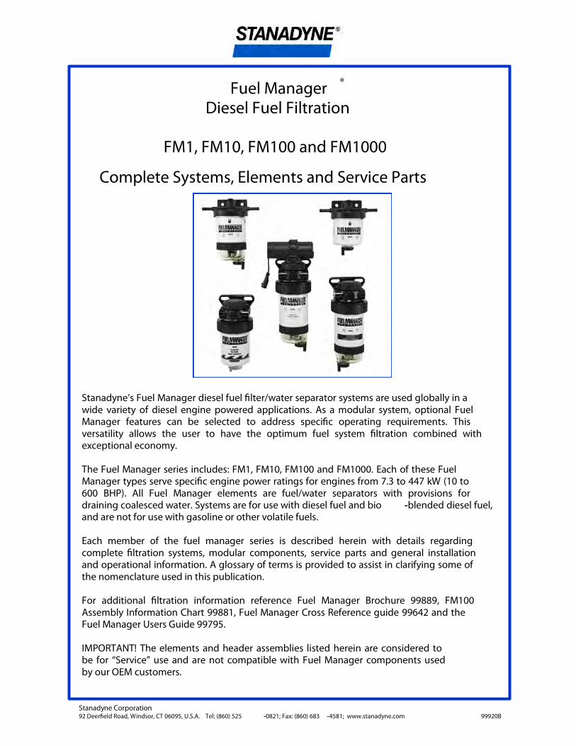
Fuel Manager ® Diesel Fuel Filtration
FM1, FM10, FM100 and FM1000
Complete Systems, Elements and Service Parts
Stanadyne’s Fuel Manager diesel fuel �lter/water separator systems are used globally in a wide variety of diesel engine powered applications. As a modular system, optional Fuel Manager features can be selected to address speci�c operating requirements. This versatility allows the user to have the optimum fuel system �ltration combined with exceptional economy.
The Fuel Manager series includes: FM1, FM10, FM100 and FM1000. Each of these Fuel Manager types serve speci�c engine power ratings for engines from 7.3 to 447 kW (10 to 600 BHP). All Fuel Manager elements are fuel/water separators with provisions for draining coalesced water. Systems are for use with diesel fuel and bio -blended diesel fuel, and are not for use with gasoline or other volatile fuels.
Each member of the fuel manager series is described herein with details regarding complete �ltration systems, modular components, service parts and general installation and operational information. A glossary of terms is provided to assist in clarifying some of the nomenclature used in this publication.
For additional �ltration information reference Fuel Manager Brochure 99889, FM100 Assembly Information Chart 99881, Fuel Manager Cross Reference guide 99642 and the Fuel Manager Users Guide 99795.
IMPORTANT! The elements and header assemblies listed herein are considered to be for “Service” use and are not compatible with Fuel Manager components used by our OEM customers.

- 1 -
Glossary of Terms
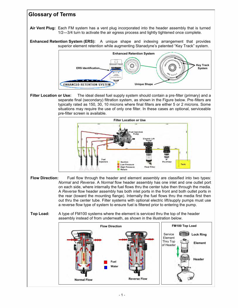
Air Vent Plug: Each FM system has a vent plug incorporated into the header assembly that is turned 1/2—3/4 turn to activate the air egress process and lightly tightened once complete.
Enhanced Retention System (ERS): A unique shape and indexing arrangement that provides
superior element retention while augmenting Stanadyne’s patented “Key Track” system.
Filter Location or Use: The ideal diesel fuel supply system should contain a pre-filter (primary) and a separate final (secondary) filtration system, as shown in the Figure below. Pre-filters are typically rated as 150, 30, 10 microns where final filters are either 5 or 2 microns. Some situations may require the use of only one filter. In these cases an optional, serviceable pre-filter screen is available.
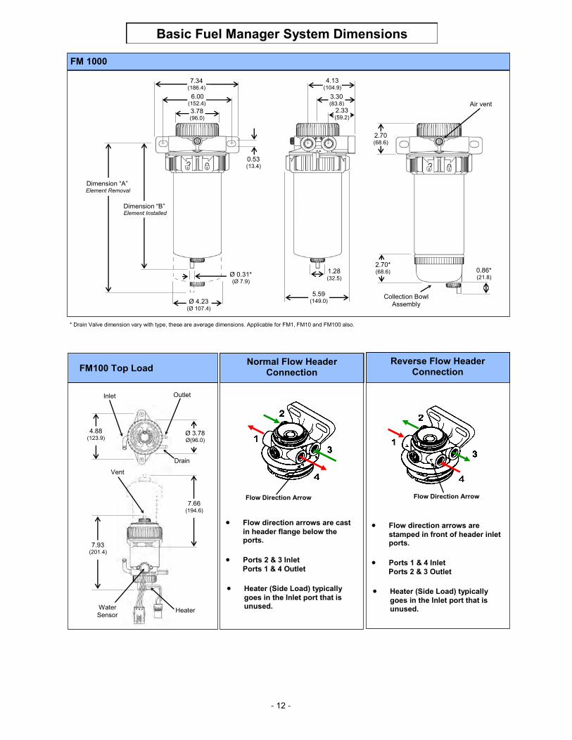
Flow Direction: Fuel flow through the header and element assembly are classified into two types: Normal and Reverse. A Normal flow header assembly has one inlet and one outlet port on each side, where internally the fuel flows thru the center tube then through the media. A Reverse flow header assembly has both inlet ports in the front and both outlet ports in the rear (toward the mounting flange). Internally the fuel flows thru the media first then out thru the center tube. Filter systems with optional electric lift/supply pumps must use a reverse flow type of system to ensure fuel is filtered prior to entering the pump.
Top Load: A type of FM100 systems where the element is serviced thru the top of the header
assembly instead of from underneath, as shown in the illustration below.
Fuel
Water
Flow Direction FM100 Top Load
Header
Element
Lock Ring Service Element Thru Top of Header
Filter Location or Use
ERS Identification
Unique Shape
Key Track System
Enhanced Retention System
- 2 -
FM1 Service Replacement Elements
Element Part No. Use Micron Rating Element Length Pkg. Qty.
40070 Final Filter 5 2.8 (71.1) 12
40072 Final Filter 5 3.6 (91.4) 12
40096 Final Filter 5 4.3 (109.2) 12
42139 Pre-Filter 30 2.8 (71.1) 12
42140 Pre-Filter 30 3.6 (91.4) 12
42141 Pre-Filter 30 4.3 (109.2) 12
FM1 Complete Filter/Water Separator Systems
System Part No. Use
Micron Rating Components
Element Part No.
Element Length Dim. “A”2 Dim “B”2
Pkg. Qty.
40074 Final Filter 5 Air Vent Plug 40072 3.6 (91.4) 5.9 (149.6) 5.3 (133.6) 1
41467 Final Filter 5 Water Collection Bowl , Air Vent plug 40072 3.6 (91.4) 7.6 (193.0) 7.0 (178.2) 1
42145 Pre-Filter 30 Air Vent Plug 42140 3.6 (91.4) 5.9 (149.6) 5.3 (133.6) 1
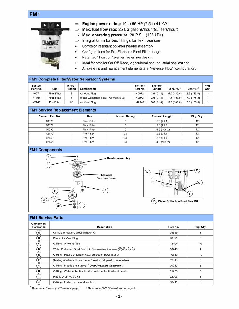
FM1 Components
C
Element (See Table Above)
Header Assembly B
F
I
F A
E
G†
Water Collection Bowl Seal Kit D
H E
G† J
F
FM1 Service Parts
Component Reference Description Part No. Pkg. Qty.
A Complete Water Collection Bowl Kit 29899 1
B Plastic Air Vent Plug 28691 6
C O-Ring - Air Vent Plug 13494 10
D Water Collection Bowl Seal Kit (Contains 6 each of seals E F H J ) 30448 1
E O-Ring - Filter element to water collection bowl header 10519 10
F Sealing Washer - Three “Lobed” seal for all plastic drain valves 32010 5
G O-Ring - Plastic drain valve †Only Available Separately 29210 5
H O-Ring - Water collection bowl to water collection bowl header 31498 5
I Plastic Drain Valve Kit 32003 1
J O-Ring - Collection bowl draw bolt 30911 5
1 Reference Glossary of Terms on page 1. 2 Reference FM1 Dimensions on page 11.
FM1
Engine power rating: 10 to 55 HP (7.5 to 41 kW)
Max. fuel flow rate: 25 US gallons/hour (95 liters/hour)
Max. operating pressure: 20 P.S.I. (138 kPa)
Integral 8mm barbed fittings for flex hose use
Corrosion resistant polymer header assembly
Configurations for Pre-Filter and Final Filter usage
Patented “Twist on” element retention design
Ideal for smaller On-Off Road, Agricultural and Industrial applications.
All systems and replacement elements are “Reverse Flow” 1 configuration.
- 3 -
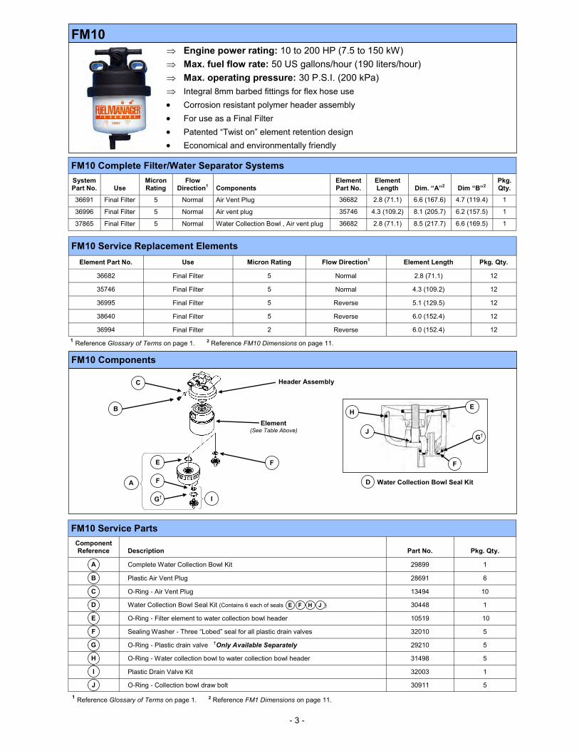
FM10 Engine power rating: 10 to 200 HP (7.5 to 150 kW)
Max. fuel flow rate: 50 US gallons/hour (190 liters/hour)
Max. operating pressure: 30 P.S.I. (200 kPa)
Integral 8mm barbed fittings for flex hose use
Corrosion resistant polymer header assembly
For use as a Final Filter
Patented “Twist on” element retention design
Economical and environmentally friendly
1 Reference Glossary of Terms on page 1. 2 Reference FM10 Dimensions on page 11.
FM10 Complete Filter/Water Separator Systems
System Part No. Use
Micron Rating
Flow Direction1 Components
Element Part No.
Element Length Dim. “A”2 Dim “B”2
Pkg. Qty.
36691 Final Filter 5 Normal Air Vent Plug 36682 2.8 (71.1) 6.6 (167.6) 4.7 (119.4) 1
36996 Final Filter 5 Normal Air vent plug 35746 4.3 (109.2) 8.1 (205.7) 6.2 (157.5) 1
37865 Final Filter 5 Normal Water Collection Bowl , Air vent plug 36682 2.8 (71.1) 8.5 (217.7) 6.6 (169.5) 1
FM10 Service Replacement Elements
Element Part No. Use Micron Rating Flow Direction1 Element Length Pkg. Qty.
36682 Final Filter 5 Normal 2.8 (71.1) 12
35746 Final Filter 5 Normal 4.3 (109.2) 12
36995 Final Filter 5 Reverse 5.1 (129.5) 12
38640 Final Filter 5 Reverse 6.0 (152.4) 12
36994 Final Filter 2 Reverse 6.0 (152.4) 12
FM10 Components
FM10 Service Parts
Component Reference Description Part No. Pkg. Qty.
A Complete Water Collection Bowl Kit 29899 1
B Plastic Air Vent Plug 28691 6
C O-Ring - Air Vent Plug 13494 10
D Water Collection Bowl Seal Kit (Contains 6 each of seals E F H J ) 30448 1
E O-Ring - Filter element to water collection bowl header 10519 10
F Sealing Washer - Three “Lobed” seal for all plastic drain valves 32010 5
G O-Ring - Plastic drain valve †Only Available Separately 29210 5
H O-Ring - Water collection bowl to water collection bowl header 31498 5
I Plastic Drain Valve Kit 32003 1
J O-Ring - Collection bowl draw bolt 30911 5
1 Reference Glossary of Terms on page 1. 2 Reference FM1 Dimensions on page 11.
A
C
Element (See Table Above)
Header Assembly
B
F
I
F
E
G†
Water Collection Bowl Seal Kit D
H E
G† J
F
- 4 -
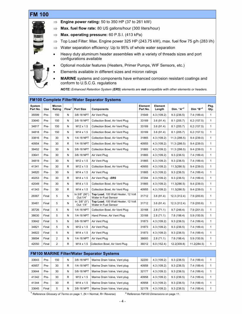
FM 100
Engine power rating: 50 to 350 HP (37 to 261 kW)
Max. fuel flow rate: 80 US gallons/hour (300 liters/hour)
Max. operating pressure: 60 P.S.I. (413 kPa)
Top Load Filter: Max. Engine power 325 HP (243.75 kW), max. fuel flow 75 g/h (283 l/h)
Water separation efficiency: Up to 95% of whole water separation
Heavy duty aluminum header assemblies with a variety of threads sizes and port configurations available
Optional modular features (Heaters, Primer Pumps, WIF Sensors, etc.)
Elements available in different sizes and micron ratings
MARINE systems and components have enhanced corrosion resistant coatings and conform to U.S.C.G. regulations
NOTE: Enhanced Retention System (ERS) elements are not compatible with other elements or headers.
FM100 Complete Filter/Water Separator Systems
System Part No. Use
Micron Rating Flow1 Port Size Components
Element Part No.
Element Length Dim. “A”2 Dim “B”2
Pkg. Qty.
35599 Pre- 150 N 3/8-18 NPT Air Vent Plug 31649 4.3 (109.2) 9.3 (236.5) 7.4 (189.4) 1
33640 Pre- 150 N 3/8-18 NPT Collection Bowl, Air Vent Plug 33169 3.6 (91.4) 8.1 (205.7) 6.2 (157.5) 1
34817 Pre- 150 N M12 x 1.5 Collection Bowl, Air Vent Plug 33169 3.6 (91.4) 8.1 (205.7) 6.2 (157.5) 1
34818 Pre- 150 N M14 x 1.5 Collection Bowl, Air Vent Plug 33169 3.6 (91.4) 8.1 (205.7) 6.2 (157.5) 1
33816 Pre- 30 N 1/4-18 NPT Collection Bowl, Air Vent Plug 31865 4.3 (109.2) 11.3 (286.5) 9.4 (239.0) 1
40954 Pre- 30 R 1/4-18 NPT Collection Bowl, Air Vent Plug 40955 4.3 (109.2) 11.3 (286.5) 9.4 (239.0) 1
39452 Pre- 30 N 3/8-18 NPT Collection Bowl, Air Vent Plug 31865 4.3 (109.2) 11.3 (286.5) 9.4 (239.0) 1
33641 Pre- 30 N 3/8-18 NPT Air Vent Plug 31865 4.3 (109.2) 9.3 (236.5) 7.4 (189.4) 1
34819 Pre- 30 N M12 x 1.5 Air Vent Plug 31865 4.3 (109.2) 9.3 (236.5) 7.4 (189.4) 1
41341 Pre- 30 R M12 x 1.5 Collection Bowl, Air Vent Plug 40955 4.3 (109.2) 11.3(286.5) 9.4 (239.0) 1
34820 Pre- 30 N M14 x 1.5 Air Vent Plug 31865 4.3 (109.2) 9.3 (236.5) 7.4 (189.4) 1
40253 Pre- 30 R M14 x 1.5 Air Vent Plug - ERS 37294 4.3 (109.2) 9.3 (236.5) 7.4 (189.4) 1
42049 Pre- 30 N M14 x 1.5 Collection Bowl, Air Vent Plug 31865 4.3 (109.2) 11.3(286.5) 9.4 (239.0) 1
41343 Pre- 30 R M14 x 1.5 Collection Bowl, Air Vent Plug 40955 4.3 (109.2) 11.3(286.5) 9.4 (239.0) 1
29367 Final 5 N In:3/8” (90°)
Out:1/4”
Top Load, 100 Watt Heater, 12 Volt
Water in Fuel Sensor 31712 3.6 (91.4) 12.3 (312.4) 7.9 (200.6) 1
30481 Final 5 N In: 3/8” (0°)
Out: 1/4”
Top Load, 100 Watt Heater, 12 Volt
Water in Fuel Sensor 31712 3.6 (91.4) 12.3 (312.4) 7.9 (200.6) 1
35726 Final 5 N 1/4-18 NPT Collection Bowl, Air Vent Plug 33168 2.8 (71.1) 9.7 (248.4) 7.9 (201.0) 1
38630 Final 5 N 1/4-18 NPT Hand Primer, Air Vent Plug 33168 2.8 (71.1) 7.8 (198.4) 5.9 (150.9) 1
33642 Final 5 N 3/8-18 NPT Air Vent Plug 31873 4.3 (109.2) 9.3 (236.5) 7.4 (189.4) 1
34821 Final 5 N M12 x 1.5 Air Vent Plug 31873 4.3 (109.2) 9.3 (236.5) 7.4 (189.4) 1
34822 Final 5 N M14 x 1.5 Air Vent Plug 31873 4.3 (109.2) 9.3 (236.5) 7.4 (189.4) 1
36694 Final 2 N 1/4-18 NPT Air Vent Plug 36693 2.8 (71.1) 7.8 (198.4) 5.9 (150.9) 1
42050 Final 2 R M14 x 1.5 Collection Bowl, Air Vent Plug 36012 6.0 (152.4) 12.2(309.8) 11.2(284.5) 1
FM100 MARINE Filter/Water Separator Systems
33643 Pre- 150 N 3/8-18 NPT Marine Drain Valve, Vent plug 32200 4.3 (109.2) 9.3 (236.5) 7.4 (189.4) 1
40957 Pre- 30 R 1/4-18 NPT Marine Drain Valve, Vent plug 40958 4.3 (109.2) 9.3 (236.5) 7.4 (189.4) 1
33644 Pre- 30 N 3/8-18 NPT Marine Drain Valve, Vent plug 32177 4.3 (109.2) 9.3 (236.5) 7.4 (189.4) 1
41342 Pre- 30 R M12 x 1.5 Marine Drain Valve, Vent plug 40958 4.3 (109.2) 9.3 (236.5) 7.4 (189.4) 1
41344 Pre- 30 R M14 x 1.5 Marine Drain Valve, Vent plug 40958 4.3 (109.2) 9.3 (236.5) 7.4 (189.4) 1
33645 Final 5 N 3/8-18 NPT Marine Drain Valve, Vent plug 32178 4.3 (109.2) 9.3 (236.5) 7.4 (189.4) 1
1 Reference Glossary of Terms on page 1. (N = Normal, R= Reverse) 2 Reference FM100 Dimensions on page 11.
- 5 -
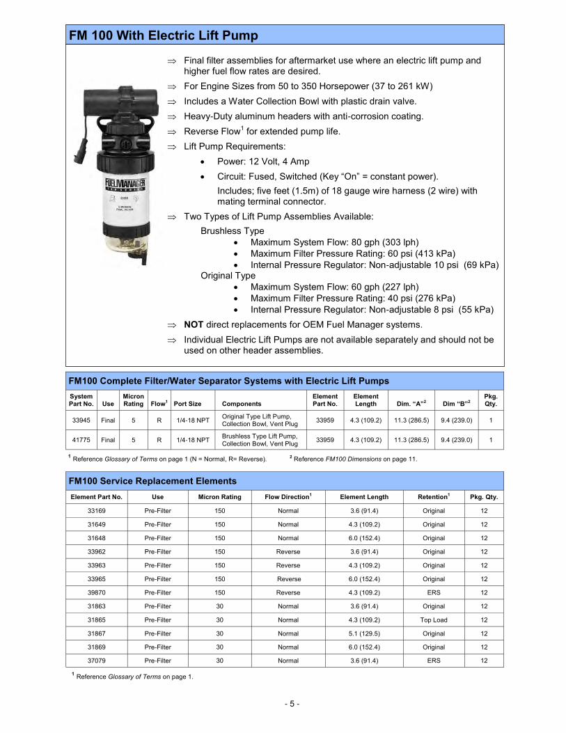
FM 100 With Electric Lift Pump
Final filter assemblies for aftermarket use where an electric lift pump and higher fuel flow rates are desired.
For Engine Sizes from 50 to 350 Horsepower (37 to 261 kW)
Includes a Water Collection Bowl with plastic drain valve.
Heavy-Duty aluminum headers with anti-corrosion coating.
Reverse Flow1 for extended pump life.
Lift Pump Requirements:
Power: 12 Volt, 4 Amp
Circuit: Fused, Switched (Key “On” = constant power).
Includes; five feet (1.5m) of 18 gauge wire harness (2 wire) with mating terminal connector.
Two Types of Lift Pump Assemblies Available:
Brushless Type
Maximum System Flow: 80 gph (303 lph)
Maximum Filter Pressure Rating: 60 psi (413 kPa)
Internal Pressure Regulator: Non-adjustable 10 psi (69 kPa) Original Type
Maximum System Flow: 60 gph (227 lph)
Maximum Filter Pressure Rating: 40 psi (276 kPa)
Internal Pressure Regulator: Non-adjustable 8 psi (55 kPa)
NOT direct replacements for OEM Fuel Manager systems.
Individual Electric Lift Pumps are not available separately and should not be used on other header assemblies.
1 Reference Glossary of Terms on page 1 (N = Normal, R= Reverse). 2 Reference FM100 Dimensions on page 11.
FM100 Complete Filter/Water Separator Systems with Electric Lift Pumps
System Part No. Use
Micron Rating Flow1 Port Size Components
Element Part No.
Element Length Dim. “A”2 Dim “B”2
Pkg. Qty.
33945 Final 5 R 1/4-18 NPT Original Type Lift Pump, Collection Bowl, Vent Plug
33959 4.3 (109.2) 11.3 (286.5) 9.4 (239.0) 1
41775 Final 5 R 1/4-18 NPT Brushless Type Lift Pump, Collection Bowl, Vent Plug
33959 4.3 (109.2) 11.3 (286.5) 9.4 (239.0) 1
1 Reference Glossary of Terms on page 1.
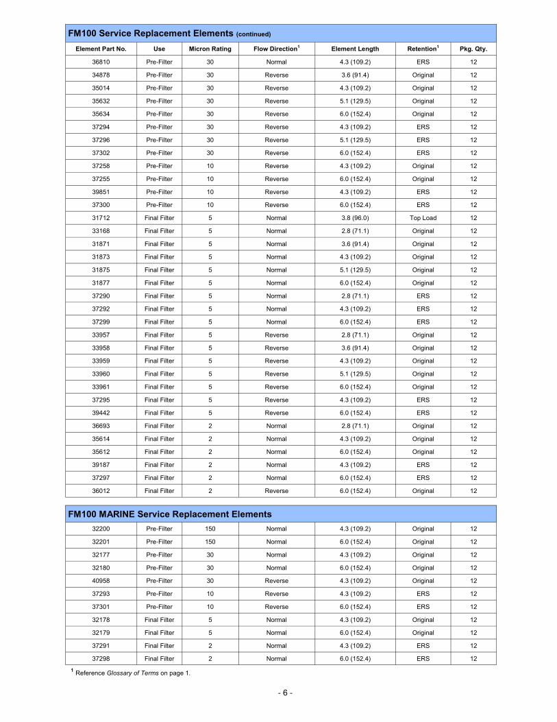
FM100 Service Replacement Elements
Element Part No. Use Micron Rating Flow Direction1 Element Length Retention1 Pkg. Qty.
33169 Pre-Filter 150 Normal 3.6 (91.4) Original 12
31649 Pre-Filter 150 Normal 4.3 (109.2) Original 12
31648 Pre-Filter 150 Normal 6.0 (152.4) Original 12
33962 Pre-Filter 150 Reverse 3.6 (91.4) Original 12
33963 Pre-Filter 150 Reverse 4.3 (109.2) Original 12
33965 Pre-Filter 150 Reverse 6.0 (152.4) Original 12
39870 Pre-Filter 150 Reverse 4.3 (109.2) ERS 12
31863 Pre-Filter 30 Normal 3.6 (91.4) Original 12
31865 Pre-Filter 30 Normal 4.3 (109.2) Top Load 12
31867 Pre-Filter 30 Normal 5.1 (129.5) Original 12
31869 Pre-Filter 30 Normal 6.0 (152.4) Original 12
37079 Pre-Filter 30 Normal 3.6 (91.4) ERS 12
- 6 -
FM100 Service Replacement Elements (continued)
Element Part No. Use Micron Rating Flow Direction1 Element Length Retention1 Pkg. Qty.
36810 Pre-Filter 30 Normal 4.3 (109.2) ERS 12
34878 Pre-Filter 30 Reverse 3.6 (91.4) Original 12
35014 Pre-Filter 30 Reverse 4.3 (109.2) Original 12
35632 Pre-Filter 30 Reverse 5.1 (129.5) Original 12
35634 Pre-Filter 30 Reverse 6.0 (152.4) Original 12
37294 Pre-Filter 30 Reverse 4.3 (109.2) ERS 12
37296 Pre-Filter 30 Reverse 5.1 (129.5) ERS 12
37302 Pre-Filter 30 Reverse 6.0 (152.4) ERS 12
37258 Pre-Filter 10 Reverse 4.3 (109.2) Original 12
37255 Pre-Filter 10 Reverse 6.0 (152.4) Original 12
39851 Pre-Filter 10 Reverse 4.3 (109.2) ERS 12
37300 Pre-Filter 10 Reverse 6.0 (152.4) ERS 12
31712 Final Filter 5 Normal 3.8 (96.0) Top Load 12
33168 Final Filter 5 Normal 2.8 (71.1) Original 12
31871 Final Filter 5 Normal 3.6 (91.4) Original 12
31873 Final Filter 5 Normal 4.3 (109.2) Original 12
31875 Final Filter 5 Normal 5.1 (129.5) Original 12
31877 Final Filter 5 Normal 6.0 (152.4) Original 12
37290 Final Filter 5 Normal 2.8 (71.1) ERS 12
37292 Final Filter 5 Normal 4.3 (109.2) ERS 12
37299 Final Filter 5 Normal 6.0 (152.4) ERS 12
33957 Final Filter 5 Reverse 2.8 (71.1) Original 12
33958 Final Filter 5 Reverse 3.6 (91.4) Original 12
33959 Final Filter 5 Reverse 4.3 (109.2) Original 12
33960 Final Filter 5 Reverse 5.1 (129.5) Original 12
33961 Final Filter 5 Reverse 6.0 (152.4) Original 12
37295 Final Filter 5 Reverse 4.3 (109.2) ERS 12
39442 Final Filter 5 Reverse 6.0 (152.4) ERS 12
36693 Final Filter 2 Normal 2.8 (71.1) Original 12
35614 Final Filter 2 Normal 4.3 (109.2) Original 12
35612 Final Filter 2 Normal 6.0 (152.4) Original 12
39187 Final Filter 2 Normal 4.3 (109.2) ERS 12
37297 Final Filter 2 Normal 6.0 (152.4) ERS 12
36012 Final Filter 2 Reverse 6.0 (152.4) Original 12
FM100 MARINE Service Replacement Elements
32200 Pre-Filter 150 Normal 4.3 (109.2) Original 12
32201 Pre-Filter 150 Normal 6.0 (152.4) Original 12
32177 Pre-Filter 30 Normal 4.3 (109.2) Original 12
32180 Pre-Filter 30 Normal 6.0 (152.4) Original 12
40958 Pre-Filter 30 Reverse 4.3 (109.2) Original 12
37293 Pre-Filter 10 Reverse 4.3 (109.2) ERS 12
37301 Pre-Filter 10 Reverse 6.0 (152.4) ERS 12
32178 Final Filter 5 Normal 4.3 (109.2) Original 12
32179 Final Filter 5 Normal 6.0 (152.4) Original 12
37291 Final Filter 2 Normal 4.3 (109.2) ERS 12
37298 Final Filter 2 Normal 6.0 (152.4) ERS 12
1 Reference Glossary of Terms on page 1.
- 7-
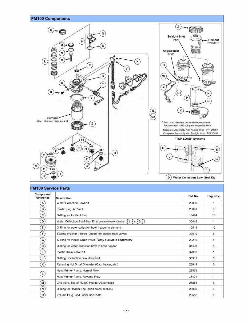
FM100 Service Parts
Component
Reference Description Part No. Pkg. Qty.
A Water Collection Bowl Kit 29899 1
B Plastic plug, Air Vent 28691 6
C O-Ring for Air Vent Plug 13494 10
D Water Collection Bowl Seal Kit (Contains 6 each of seals: E , F , H , J ) 30448 1
E O-Ring for water collection bowl header to element 10519 10
F Sealing Washer - Three “Lobed” for plastic drain valves 32010 5
G O-Ring for Plastic Drain Valve †Only available Separately 29210 5
H O-Ring for water collection bowl to bowl header 31498 5
I Plastic Drain Valve Kit 32003 1
J O-Ring - Collection bowl draw bolt 30911 5
K Retaining Nut Small Diameter (Cap, heater, etc.) 28849 6
L Hand Primer Pump, Normal Flow 29578 1
Hand Primer Pump, Reverse Flow 35474 1
M Cap plate, Top of FM100 Header Assemblies 28853 6
N O-Ring for Header Top (quad cross-section) 28869 6
O Volume Plug used under Cap Plate 29552 6
D
FM100 Components
Water Collection Bowl Seal Kit
H E
G† J
F
“TOP LOAD” Systems
* Top Load Headers not available separately.
Replacement is by complete assembly only.
Complete Assembly with Angled Inlet: P/N 29367
Complete Assembly with Straight Inlet: P/N 30481
Angled Inlet Port*
Z
Straight Inlet Port* Element
P/N 31712
W
X
I1
U1
P
N
Q
K U
U2
L
K
N
O
M N
P
Q
B
S
C
R
T
Y
Z
V
X
I
A
E
G†
F
F
I3 I2
F1
F I1
G†
Element (See Tables on Pages 5 & 6)
- 8 -
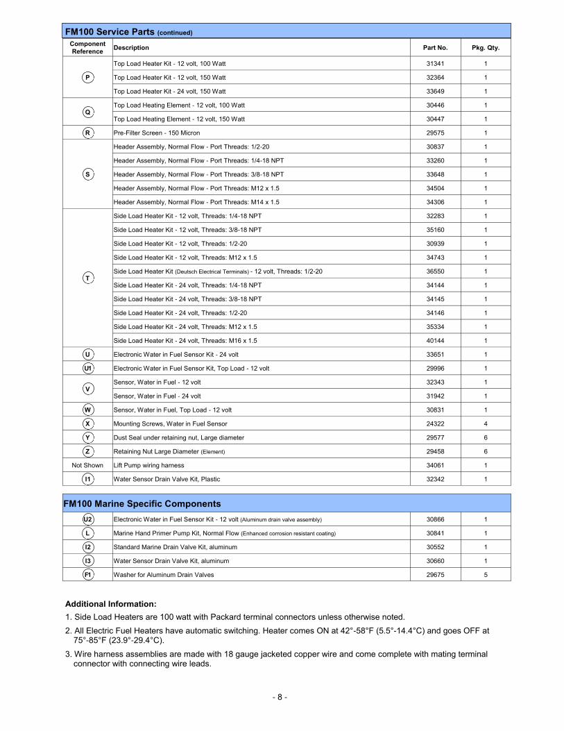
FM100 Service Parts (continued)
Component
Reference Description Part No. Pkg. Qty.
P
Top Load Heater Kit - 12 volt, 100 Watt 31341 1
Top Load Heater Kit - 12 volt, 150 Watt 32364 1
Top Load Heater Kit - 24 volt, 150 Watt 33649 1
Q Top Load Heating Element - 12 volt, 100 Watt 30446 1
Top Load Heating Element - 12 volt, 150 Watt 30447 1
R Pre-Filter Screen - 150 Micron 29575 1
S
Header Assembly, Normal Flow - Port Threads: 1/2-20 30837 1
Header Assembly, Normal Flow - Port Threads: 1/4-18 NPT 33260 1
Header Assembly, Normal Flow - Port Threads: 3/8-18 NPT 33648 1
Header Assembly, Normal Flow - Port Threads: M12 x 1.5 34504 1
Header Assembly, Normal Flow - Port Threads: M14 x 1.5 34306 1
T
Side Load Heater Kit - 12 volt, Threads: 1/4-18 NPT 32283 1
Side Load Heater Kit - 12 volt, Threads: 3/8-18 NPT 35160 1
Side Load Heater Kit - 12 volt, Threads: 1/2-20 30939 1
Side Load Heater Kit - 12 volt, Threads: M12 x 1.5 34743 1
Side Load Heater Kit (Deutsch Electrical Terminals) - 12 volt, Threads: 1/2-20 36550 1
Side Load Heater Kit - 24 volt, Threads: 1/4-18 NPT 34144 1
Side Load Heater Kit - 24 volt, Threads: 3/8-18 NPT 34145 1
Side Load Heater Kit - 24 volt, Threads: 1/2-20 34146 1
Side Load Heater Kit - 24 volt, Threads: M12 x 1.5 35334 1
Side Load Heater Kit - 24 volt, Threads: M16 x 1.5 40144 1
U Electronic Water in Fuel Sensor Kit - 24 volt 33651 1
U1 Electronic Water in Fuel Sensor Kit, Top Load - 12 volt 29996 1
V Sensor, Water in Fuel - 12 volt 32343 1
Sensor, Water in Fuel - 24 volt 31942 1
W Sensor, Water in Fuel, Top Load - 12 volt 30831 1
X Mounting Screws, Water in Fuel Sensor 24322 4
Y Dust Seal under retaining nut, Large diameter 29577 6
Z Retaining Nut Large Diameter (Element) 29458 6
Not Shown Lift Pump wiring harness 34061 1
I 1 Water Sensor Drain Valve Kit, Plastic 32342 1
FM100 Marine Specific Components
U2 Electronic Water in Fuel Sensor Kit - 12 volt (Aluminum drain valve assembly) 30866 1
L Marine Hand Primer Pump Kit, Normal Flow (Enhanced corrosion resistant coating) 30841 1
I 2 Standard Marine Drain Valve Kit, aluminum 30552 1
I 3 Water Sensor Drain Valve Kit, aluminum 30660 1
F1 Washer for Aluminum Drain Valves 29675 5
Additional Information:
1. Side Load Heaters are 100 watt with Packard terminal connectors unless otherwise noted.
2. All Electric Fuel Heaters have automatic switching. Heater comes ON at 42°-58°F (5.5°-14.4°C) and goes OFF at 75°-85°F (23.9°-29.4°C).
3. Wire harness assemblies are made with 18 gauge jacketed copper wire and come complete with mating terminal connector with connecting wire leads.
- 9 -
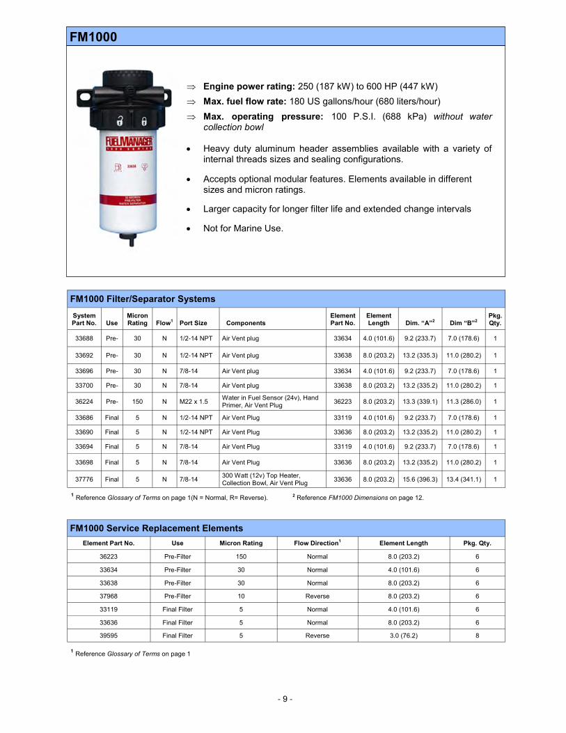
FM1000
Engine power rating: 250 (187 kW) to 600 HP (447 kW)
Max. fuel flow rate: 180 US gallons/hour (680 liters/hour)
Max. operating pressure: 100 P.S.I. (688 kPa) without water collection bowl
Heavy duty aluminum header assemblies available with a variety of internal threads sizes and sealing configurations.
Accepts optional modular features. Elements available in different sizes and micron ratings.
Larger capacity for longer filter life and extended change intervals
Not for Marine Use.
1 Reference Glossary of Terms on page 1(N = Normal, R= Reverse). 2 Reference FM1000 Dimensions on page 12.
FM1000 Filter/Separator Systems
System Part No. Use
Micron Rating Flow1 Port Size Components
Element Part No.
Element Length Dim. “A”2 Dim “B”2
Pkg. Qty.
33688 Pre- 30 N 1/2-14 NPT Air Vent plug 33634 4.0 (101.6) 9.2 (233.7) 7.0 (178.6) 1
33692 Pre- 30 N 1/2-14 NPT Air Vent plug 33638 8.0 (203.2) 13.2 (335.3) 11.0 (280.2) 1
33696 Pre- 30 N 7/8-14 Air Vent plug 33634 4.0 (101.6) 9.2 (233.7) 7.0 (178.6) 1
33700 Pre- 30 N 7/8-14 Air Vent plug 33638 8.0 (203.2) 13.2 (335.2) 11.0 (280.2) 1
36224 Pre- 150 N M22 x 1.5 Water in Fuel Sensor (24v), Hand Primer, Air Vent Plug
36223 8.0 (203.2) 13.3 (339.1) 11.3 (286.0) 1
33686 Final 5 N 1/2-14 NPT Air Vent Plug 33119 4.0 (101.6) 9.2 (233.7) 7.0 (178.6) 1
33690 Final 5 N 1/2-14 NPT Air Vent Plug 33636 8.0 (203.2) 13.2 (335.2) 11.0 (280.2) 1
33694 Final 5 N 7/8-14 Air Vent Plug 33119 4.0 (101.6) 9.2 (233.7) 7.0 (178.6) 1
33698 Final 5 N 7/8-14 Air Vent Plug 33636 8.0 (203.2) 13.2 (335.2) 11.0 (280.2) 1
37776 Final 5 N 7/8-14 300 Watt (12v) Top Heater, Collection Bowl, Air Vent Plug
33636 8.0 (203.2) 15.6 (396.3) 13.4 (341.1) 1
FM1000 Service Replacement Elements
Element Part No. Use Micron Rating Flow Direction1 Element Length Pkg. Qty.
36223 Pre-Filter 150 Normal 8.0 (203.2) 6
33634 Pre-Filter 30 Normal 4.0 (101.6) 6
33638 Pre-Filter 30 Normal 8.0 (203.2) 6
37968 Pre-Filter 10 Reverse 8.0 (203.2) 6
33119 Final Filter 5 Normal 4.0 (101.6) 6
33636 Final Filter 5 Normal 8.0 (203.2) 6
39595 Final Filter 5 Reverse 3.0 (76.2) 8
1 Reference Glossary of Terms on page 1
- 10 -
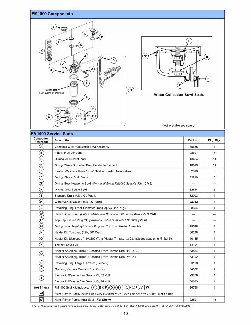
NOTE: All Electric Fuel Heaters have automatic switching. Heater comes ON at 42°-58°F (5.5°-14.4°C) and goes OFF at 75°-85°F (23.9°-29.4°C).
FM1000 Components
† Not available separately
A
I
D
F
E I1
R
Element (See Table on Page 9)
F
E
P
B
C
Q
L† M
M N
O
S
T
J
K†
G†
D
H
E
F
Water Collection Bowl Seals
FM1000 Service Parts Component
Reference Description Part No. Pkg. Qty.
A Complete Water Collection Bowl Assembly 35635 1
B Plastic Plug, Air Vent 28691 6
C O-Ring for Air Vent Plug 13494 10
D O-ring, Water Collection Bowl Header to Element 10519 10
E Sealing Washer - Three “Lobe” Seal for Plastic Drain Valves 32010 5
F O-ring, Plastic Drain Valve 29210 5
G† O-ring, Bowl Header to Bowl (Only available in FM1000 Seal Kit: P/N 36768) — —
H O-ring, Draw Bolt to Bowl 32884 5
I Standard Drain Valve Kit, Plastic 32003 1
I1 Water Sensor Drain Valve Kit, Plastic 32342 1
J Retaining Ring, Small Diameter (Top Cap/Volume Plug) 28694 1
K† Hand Primer Pump (Only available with Complete FM1000 System: P/N 36224) — —
L† Top Cap/Volume Plug (Only available with a Complete FM1000 System) — —
M O-ring under Top Cap/Volume Plug and Top Load Heater Assembly 29588 1
N Heater Kit, Top Load (12V, 300 Watt) 36238 1
O Heater Kit, Side Load (12V, 200 Watt) (Heater Thread: 1/2-20, includes adapter to M16x1.5) 40145 1
P Element Dust Seal 33104 1
Q Header Assembly, Black “E” coated (Ports Thread Size: 1/2-14 NPT) 33564 1
Header Assembly, Black “E” coated (Ports Thread Size: 7/8-14) 33102 1
R Retaining Ring, Large Diameter (Element) 33108 1
S Mounting Screws, Water in Fuel Sensor 24322 4
T Electronic Water in Fuel Sensor Kit, 12 Volt 29268 1
Electronic Water in Fuel Sensor Kit, 24 Volt 38023 1
Not Shown FM1000 Seal Kit, includes: C , E , F , G , H , I , N , R , V† , W† 36768 1
V† Hand Primer Pump, Outer Seal (Only available in FM1000 Seal Kit: P/N 36768) - Not Shown — —
W† Hand Primer Pump, Inner Seal - Not Shown 22591 10
- 11 -
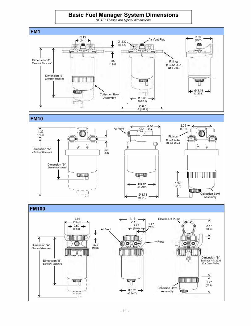
Basic Fuel Manager System Dimensions NOTE: Theses are typical dimensions.
FM10
1.22 (30.9)
Dimension “B” Element Installed
Dimension “A” Element Removal
.35 (8.8)
3.32 (84.2) Air Vent
Ø3.12 (Ø 79.2)
Ø 3.73 (Ø 94.7)
Collection Bowl Assembly
1.97 (50.0)
2.25 (57.1)
Fittings Ø .35 O.D. (Ø 8.8 O.D.)
FM100
Ø 3.73 (Ø 94.7)
Air Vent
Ports
1.47(37.3)
2.77(70.4)
4.12 (104.6)
Electric Lift Pump
Collection Bowl Assembly
1.97 (50.0)
2.57(65.3)
Dimension “B” Subtract 1.0 (25.4)
For Drain Valve Dimension “B”
Element Installed
Dimension “A” Element Removal
3.95 (100.5)
.425 (10.8)
2.50 (63.5)
FM1
Fittings Ø .312 O.D.
(Ø 8 O.D.)
Air Vent Plug
Ø 3.63 Ø (92.1)
Ø 6.0 Ø (152.4)
Ø .332 (Ø 8.4)
Ø 3.18 Ø (80.8)
3.69 (93.7)
Dimension “B” Element Installed
Dimension “A” Element Removal
Collection Bowl Assembly
2.13 (54.1)
.55 (13.9)
- 12 -
Basic Fuel Manager System Dimensions
* Drain Valve dimension vary with type, these are average dimensions. Applicable for FM1, FM10 and FM100 also.
FM 1000
Dimension “B” Element Installed
Ø 4.23 (Ø 107.4)
0.53 (13.4)
7.34(186.4)
3.78 (96.0)
6.00 (152.4)
Ø 0.31* (Ø 7.9)
5.59 (149.0)
1.28 (32.5)
2.70 (68.6)
4.13 (104.9)
Dimension “A” Element Removal
0.86* (21.8)
3.30 (83.8)
2.33 (59.2)
2.70* (68.6)
Collection Bowl Assembly
Air vent
7.66 (194.6)
4.88 (123.9)
7.93 (201.4)
Inlet Outlet
Drain
Water Sensor
Heater
Vent
Ø 3.78 Ø(96.0)
FM100 Top Load
Flow direction arrows are
stamped in front of header inlet ports.
Ports 1 & 4 Inlet
Ports 2 & 3 Outlet
Heater (Side Load) typically
goes in the Inlet port that is unused.
Reverse Flow Header Connection
Flow Direction Arrow Flow Direction Arrow
Normal Flow Header Connection
Flow direction arrows are cast
in header flange below the ports.
Ports 2 & 3 Inlet
Ports 1 & 4 Outlet
Heater (Side Load) typically
goes in the Inlet port that is unused.

99920B Rev. 31 August 2012
Stanadyne Corporation 92 Deerfield Road
Windsor, CT 06095, U.S.A Tel: (860) 525-0821 www.stanadyne.com
Stanadyne SpA Via Matteotti 158
25014 Castenedolo (Brescia), Italia Tel: (39) 030 213 0070
Stanadyne Amalgamations Private Ltd. 96, Aranvayal Village
Poonamalle-Thiruvallur High Road (Near Pratyusha Engg College)
Thiruvallur District- 602025, India Tel: +91 044 37678300
Stanadyne Changshu Corporation 155# Huangshan Road
Southeast Economy Development Zone Changshu City, 215500, Jiangsu Province
P.R.C. (People's Republic of China) Tel: + 86 512 8156 5000