Embed Size (px)
Citation preview
PNNL-19476
Prepared for the U.S. Department of Energy under Contract DE-AC05-76RL01830
Fuel Efficient Diesel Particulate Filter (DPF) Modeling and Development ML Stewart GD Maupin TR Gallant A Zelenyuk DH Kim August 2010
PNNL-19476
Fuel Efficient Diesel Particulate Filter (DPF) Modeling and Development ML Stewart GD Maupin TR Gallant A Zelenyuk DH Kim August 2010 Prepared for the U.S. Department of Energy under Contract DE-AC05-76RL01830 Pacific Northwest National Laboratory Richland, Washington 99352

iii
Summary
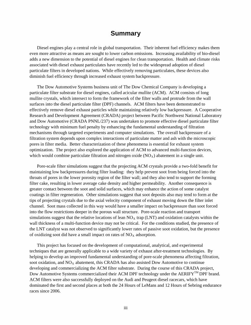
Diesel engines play a central role in global transportation. Their inherent fuel efficiency makes them even more attractive as means are sought to lower carbon emissions. Increasing availability of bio-diesel adds a new dimension to the potential of diesel engines for clean transportation. Health and climate risks associated with diesel exhaust particulates have recently led to the widespread adoption of diesel particulate filters in developed nations. While effectively removing particulates, these devices also diminish fuel efficiency through increased exhaust system backpressure.
The Dow Automotive Systems business unit of The Dow Chemical Company is developing a particulate filter substrate for diesel engines, called acicular mullite (ACM). ACM consists of long mullite crystals, which intersect to form the framework of the filter walls and protrude from the wall surfaces into the diesel particulate filter (DPF) channels. ACM filters have been demonstrated to effectively remove diesel exhaust particles while maintaining relatively low backpressure. A Cooperative Research and Development Agreement (CRADA) project between Pacific Northwest National Laboratory and Dow Automotive (CRADA PNNL/237) was undertaken to promote effective diesel particulate filter technology with minimum fuel penalty by enhancing the fundamental understanding of filtration mechanisms through targeted experiments and computer simulations. The overall backpressure of a filtration system depends upon complex interactions of particulate matter and ash with the microscopic pores in filter media. Better characterization of these phenomena is essential for exhaust system optimization. The project also explored the application of ACM to advanced multi-function devices, which would combine particulate filtration and nitrogen oxide (NOX
Pore-scale filter simulations suggest that the projecting ACM crystals provide a two-fold benefit for maintaining low backpressures during filter loading: they help prevent soot from being forced into the throats of pores in the lower porosity region of the filter wall; and they also tend to support the forming filter cake, resulting in lower average cake density and higher permeability. Another consequence is greater contact between the soot and solid surfaces, which may enhance the action of some catalyst coatings in filter regeneration. Other simulations suggest that soot deposits also may tend to form at the tips of projecting crystals due to the axial velocity component of exhaust moving down the filter inlet channel. Soot mass collected in this way would have a smaller impact on backpressure than soot forced into the flow restrictions deeper in the porous wall structure. Pore-scale reaction and transport simulations suggest that the relative locations of lean NO
) abatement in a single unit.
X trap (LNT) and oxidation catalysts within the wall thickness of a multi-function device may not be critical. For the conditions studied, the presence of the LNT catalyst was not observed to significantly lower rates of passive soot oxidation, but the presence of oxidizing soot did have a small impact on rates of NOX
This project has focused on the development of computational, analytical, and experimental techniques that are generally applicable to a wide variety of exhaust after-treatment technologies. By helping to develop an improved fundamental understanding of pore-scale phenomena affecting filtration, soot oxidation, and NO
adsorption.
X abatement, this CRADA has also assisted Dow Automotive to continue developing and commercializing the ACM filter substrate. During the course of this CRADA project, Dow Automotive Systems commercialized their ACM DPF technology under the AERIFYTM DPF brand. ACM filters were also successfully deployed on the Audi and Peugeot diesel racecars, which have dominated the first and second places at both the 24 Hours of LeMans and 12 Hours of Sebring endurance races since 2006.

v
Acknowledgments
Key Cooperative Research and Development Agreement partners included Cheng G Li, Frank Mao, Steven J Martin, Paul Vosejpka, and Michael Malanga at Dow Automotive Systems; and Aleksander J Pyzik and Robin Ziebarth in Core R&D at The Dow Chemical Company. These members of our team helped guide our research, provided test materials, and shared valuable insight. A number of additional staff in The Dow Chemical Company and Dow Automotive Systems helped to make this project possible, including Jeff Montanye and Tony Samurkus.
This work was funded through the U.S. Department of Energy Office of Vehicle Technologies. We wish to thank Ken Howden and Gurpreet Singh for their guidance and support.
In addition to the authors, a great number of staff at Pacific Northwest National Laboratory contributed guidance and technical work to this effort. These include Heather Dillon, Shelley Carlson, James Coleman, Natalio Saenz, Juan Yang, George Muntean and Darrell Herling.
The research was performed in part using the Molecular Science Computing Facility in the Environmental and Molecular Sciences Laboratory, a national scientific user facility sponsored by the U.S. Department of Energy's Office of Biological and Environmental Research and located at Pacific Northwest National Laboratory.

vii
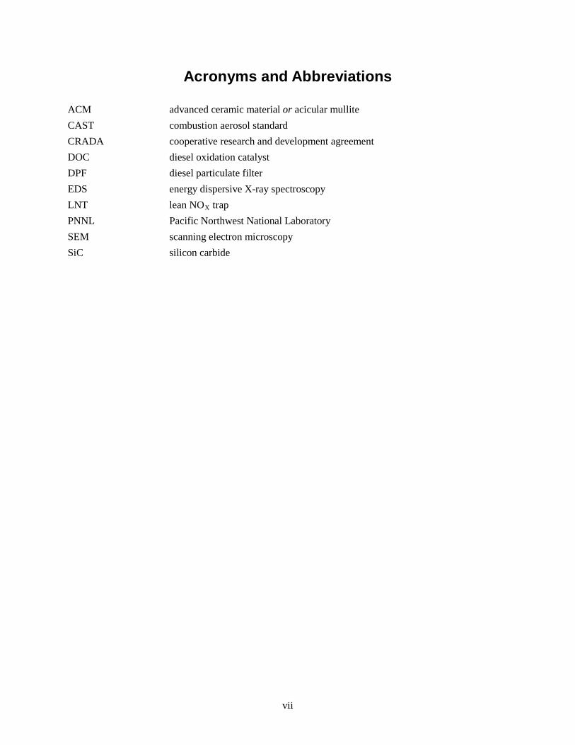
Acronyms and Abbreviations
ACM advanced ceramic material or acicular mullite CAST combustion aerosol standard CRADA cooperative research and development agreement DOC diesel oxidation catalyst DPF diesel particulate filter EDS energy dispersive X-ray spectroscopy LNT lean NOX
PNNL Pacific Northwest National Laboratory trap
SEM scanning electron microscopy SiC silicon carbide

ix
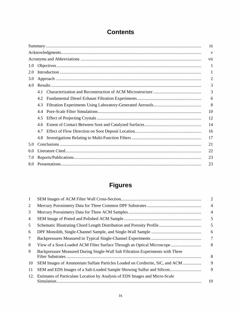
Contents
Summary ............................................................................................................................................... iiiAcknowledgments ................................................................................................................................. vAcronyms and Abbreviations ............................................................................................................... vii1.0 Objectives ..................................................................................................................................... 12.0 Introduction .................................................................................................................................. 13.0 Approach ...................................................................................................................................... 24.0 Results .......................................................................................................................................... 3
4.1 Characterization and Reconstruction of ACM Microstructure ............................................ 34.2 Fundamental Diesel Exhaust Filtration Experiments ........................................................... 64.3 Filtration Experiments Using Laboratory-Generated Aerosols ............................................ 84.4 Pore-Scale Filter Simulations ............................................................................................... 104.5 Effect of Projecting Crystals ................................................................................................ 124.6 Extent of Contact Between Soot and Catalyzed Surfaces .................................................... 144.7 Effect of Flow Direction on Soot Deposit Location ............................................................. 164.8 Investigations Relating to Multi-Function Filters ................................................................ 17
5.0 Conclusions .................................................................................................................................. 216.0 Literature Cited ............................................................................................................................. 227.0 Reports/Publications ..................................................................................................................... 238.0 Presentations ................................................................................................................................. 23
Figures
1 SEM Images of ACM Filter Wall Cross-Section .......................................................................... 22 Mercury Porosimetry Data for Three Common DPF Substrates .................................................. 43 Mercury Porosimetry Data for Three ACM Samples ................................................................... 44 SEM Image of Potted and Polished ACM Sample ....................................................................... 55 Schematic Illustrating Chord Length Distribution and Porosity Profile ....................................... 56 DPF Monolith, Single-Channel Sample, and Single-Wall Sample .............................................. 67 Backpressures Measured in Typical Single-Channel Experiments .............................................. 78 View of a Soot-Loaded ACM Filter Surface Through an Optical Microscope ............................ 89 Backpressure Measured During Single-Wall Salt Filtration Experiments with Three
Filter Substrates ............................................................................................................................ 810 SEM Images of Ammonium Sulfate Particles Loaded on Cordierite, SiC, and ACM ................. 911 SEM and EDS Images of a Salt-Loaded Sample Showing Sulfur and Silicon ............................. 912. Estimates of Particulate Location by Analysis of EDS Images and Micro-Scale
Simulation ..................................................................................................................................... 10
x
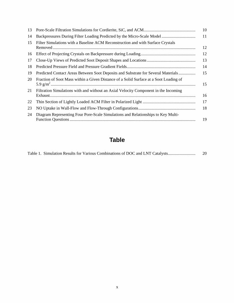
13 Pore-Scale Filtration Simulations for Cordierite, SiC, and ACM ................................................. 1014 Backpressures During Filter Loading Predicted by the Micro-Scale Model ................................ 1115 Filter Simulations with a Baseline ACM Reconstruction and with Surface Crystals
Removed ....................................................................................................................................... 1216 Effect of Projecting Crystals on Backpressure during Loading .................................................... 1217 Close-Up Views of Predicted Soot Deposit Shapes and Locations .............................................. 1318 Predicted Pressure Field and Pressure Gradient Fields ................................................................. 1419 Predicted Contact Areas Between Soot Deposits and Substrate for Several Materials ................ 1520 Fraction of Soot Mass within a Given Distance of a Solid Surface at a Soot Loading of
5.9 g/m2 ......................................................................................................................................... 1521 Filtration Simulations with and without an Axial Velocity Component in the Incoming
Exhaust .......................................................................................................................................... 1622 Thin Section of Lightly Loaded ACM Filter in Polarized Light .................................................. 1723 NO Uptake in Wall-Flow and Flow-Through Configurations ...................................................... 1824 Diagram Representing Four Pore-Scale Simulations and Relationships to Key Multi-
Function Questions ....................................................................................................................... 19
Table
Table 1. Simulation Results for Various Combinations of DOC and LNT Catalysts .......................... 20
1
1.0 Objectives
The objectives of this Cooperative Research and Development Agreement (CRADA) project are
• Develop validated computational tools for prediction of diesel particulate filter behavior including:
– Backpressure during filter loading
– Depth of soot penetration into filter substrate
– Degree of contact between soot and oxidation catalyst coatings
• Develop a fundamental understanding of the way in which the microstructure of advanced Diesel Particulate Filter (DPF) substrates affects macroscopic performance, especially backpressure and filter regeneration, which have a direct impact on overall vehicle fuel economy
• Perform fundamental modeling and experimental studies of proposed systems which combine particulate filtration and nitrogen oxide (NOX
– Explore effect of catalyst placement within the filter wall on NO
) storage and reduction functionalities in a single device
X
– Explore impact of passive filter regeneration on NO
absorption function
X
– Explore impact of NO
absorption
X
absorption on passive filter regeneration.
2.0 Introduction
High-efficiency diesel engines provide an important short- to medium-term strategy for meeting the nation’s transportation needs while minimizing emissions implicated in global climate change. However, concerns over the health effects of particulate emissions from diesel engines have prompted legislation in the United States, Europe, and Asia, which has set challenging limits on vehicular exhaust soot concentrations. DPFs have emerged as an important enabling technology to comply with these new limits. DPFs have a negative impact on fuel efficiency because they introduce backpressure to the exhaust system, and in the case of active regeneration systems, require energy to burn away collected soot. These factors must be minimized in order for high-efficiency diesel engines to provide their maximum economic and environmental benefits.
Mechanisms taking place during filtration and regeneration at the microscopic scale of pores in filter substrates are critical to DPF performance. Many different substrate materials for porous filters have been explored by industry, each with their own set of advantages and disadvantages. Currently, ceramic materials are considered to be the most practical for near-term application. The way in which soot particles interact with substrate microstructures during filtration determines removal efficiency and backpressure. Overall backpressure can also be minimized by prompt and efficient oxidation of soot trapped in the filter, which involves pore-scale transport of heat and, in many cases, active gaseous species such as nitrogen dioxide (NO2). Filtration efficiency can vary dramatically by particle size. This has important implications for human exposure to ultra-fine nanoparticles, which are suspected of posing significant health risks.
2
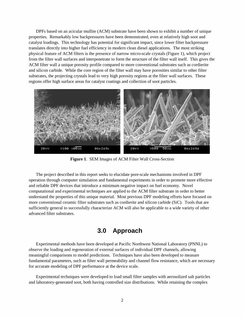
DPFs based on an acicular mullite (ACM) substrate have been shown to exhibit a number of unique properties. Remarkably low backpressures have been demonstrated, even at relatively high soot and catalyst loadings. This technology has potential for significant impact, since lower filter backpressure translates directly into higher fuel efficiency in modern clean diesel applications. The most striking physical feature of ACM filters is the presence of narrow micro-scale crystals (Figure 1), which project from the filter wall surfaces and interpenetrate to form the structure of the filter wall itself. This gives the ACM filter wall a unique porosity profile compared to more conventional substrates such as cordierite and silicon carbide. While the core region of the filter wall may have porosities similar to other filter substrates, the projecting crystals lead to very high porosity regions at the filter wall surfaces. These regions offer high surface areas for catalyst coatings and collection of soot particles.
Figure 1. SEM Images of ACM Filter Wall Cross-Section
The project described in this report seeks to elucidate pore-scale mechanisms involved in DPF
operation through computer simulation and fundamental experiments in order to promote more effective and reliable DPF devices that introduce a minimum negative impact on fuel economy. Novel computational and experimental techniques are applied to the ACM filter substrate in order to better understand the properties of this unique material. Most previous DPF modeling efforts have focused on more conventional ceramic filter substrates such as cordierite and silicon carbide (SiC). Tools that are sufficiently general to successfully characterize ACM will also be applicable to a wide variety of other advanced filter substrates.
3.0 Approach
Experimental methods have been developed at Pacific Northwest National Laboratory (PNNL) to observe the loading and regeneration of external surfaces of individual DPF channels, allowing meaningful comparisons to model predictions. Techniques have also been developed to measure fundamental parameters, such as filter wall permeability and channel flow resistance, which are necessary for accurate modeling of DPF performance at the device scale.
Experimental techniques were developed to load small filter samples with aerosolized salt particles and laboratory-generated soot, both having controlled size distributions. While retaining the complex
3
fractal structure of diesel soot, particles generated with laboratory systems, such as the Combustion Aerosol Standard (CAST) systems marketed by Jing Ltd of Switzerland, allow much better control and reproducibility than can usually be achieved with a diesel engine. Salt particles allow another level of simplification since they are roughly spherical in shape. In addition, unlike soot, some salts can be easily distinguished from filter substrates using techniques such as energy dispersive x-ray spectroscopy (EDS). This allows quantitative examination of the degree of particulate penetration into the filter wall, which is a critical factor in determining backpressure.
A computer model has been developed to predict the nature and location of soot deposits within porous filter substrates by simulating the flight and deposition of individual soot particles [1,2]. Detailed digital maps of the microscopic pores in various substrate materials are created using a novel stochastic reconstruction technique. The lattice-Boltzmann method is used to solve for the flow field of exhaust through the substrate microstructure as soot deposits form. The paths of simulated soot particles are derived from the exhaust flow field and include random Brownian motion. Simulations with various DPF substrates, including cordierite and silicon carbide as well as ACM, show how the substrate microstructures affect filtration performance.
The micro-scale model has also been extended to include the transport of active gaseous species, oxidation of accumulated soot, catalytic conversion of nitrogen oxide (NO) to NO2, and catalytic storage of NOX. Parametric studies were conducted to examine the effect of substrate microstructure on net rates of soot consumption. Additional parametric studies were carried out to better understand the possible interactions between filtration and NOX storage reactions in a proposed device to combine the functions of a DPF and a lean NOX
trap (LNT).
4.0 Results
4.1 Characterization and Reconstruction of ACM Microstructure
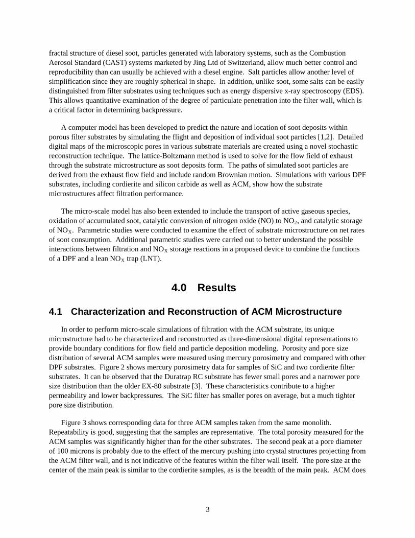
In order to perform micro-scale simulations of filtration with the ACM substrate, its unique microstructure had to be characterized and reconstructed as three-dimensional digital representations to provide boundary conditions for flow field and particle deposition modeling. Porosity and pore size distribution of several ACM samples were measured using mercury porosimetry and compared with other DPF substrates. Figure 2 shows mercury porosimetry data for samples of SiC and two cordierite filter substrates. It can be observed that the Duratrap RC substrate has fewer small pores and a narrower pore size distribution than the older EX-80 substrate [3]. These characteristics contribute to a higher permeability and lower backpressures. The SiC filter has smaller pores on average, but a much tighter pore size distribution.
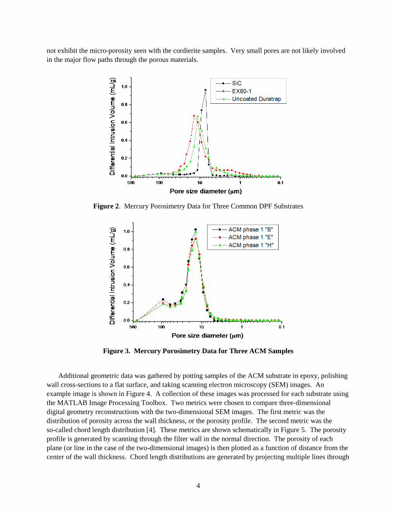
Figure 3 shows corresponding data for three ACM samples taken from the same monolith. Repeatability is good, suggesting that the samples are representative. The total porosity measured for the ACM samples was significantly higher than for the other substrates. The second peak at a pore diameter of 100 microns is probably due to the effect of the mercury pushing into crystal structures projecting from the ACM filter wall, and is not indicative of the features within the filter wall itself. The pore size at the center of the main peak is similar to the cordierite samples, as is the breadth of the main peak. ACM does
4
not exhibit the micro-porosity seen with the cordierite samples. Very small pores are not likely involved in the major flow paths through the porous materials.
Figure 2. Mercury Porosimetry Data for Three Common DPF Substrates
Figure 3. Mercury Porosimetry Data for Three ACM Samples
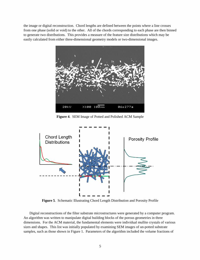
Additional geometric data was gathered by potting samples of the ACM substrate in epoxy, polishing
wall cross-sections to a flat surface, and taking scanning electron microscopy (SEM) images. An example image is shown in Figure 4. A collection of these images was processed for each substrate using the MATLAB Image Processing Toolbox. Two metrics were chosen to compare three-dimensional digital geometry reconstructions with the two-dimensional SEM images. The first metric was the distribution of porosity across the wall thickness, or the porosity profile. The second metric was the so-called chord length distribution [4]. These metrics are shown schematically in Figure 5. The porosity profile is generated by scanning through the filter wall in the normal direction. The porosity of each plane (or line in the case of the two-dimensional images) is then plotted as a function of distance from the center of the wall thickness. Chord length distributions are generated by projecting multiple lines through
5
the image or digital reconstruction. Chord lengths are defined between the points where a line crosses from one phase (solid or void) to the other. All of the chords corresponding to each phase are then binned to generate two distributions. This provides a measure of the feature size distributions which may be easily calculated from either three-dimensional geometry models or two-dimensional images.
Figure 4. SEM Image of Potted and Polished ACM Sample
Figure 5. Schematic Illustrating Chord Length Distribution and Porosity Profile
Digital reconstructions of the filter substrate microstructures were generated by a computer program.
An algorithm was written to manipulate digital building blocks of the porous geometries in three dimensions. For the ACM material, the fundamental elements were individual mullite crystals of various sizes and shapes. This list was initially populated by examining SEM images of un-potted substrate samples, such as those shown in Figure 1. Parameters of the algorithm included the volume fractions of
6
the various fundamental elements, a target porosity at the center of the filter wall, minimum and maximum intersections between new elements and those already present in the geometry, and spatial constraints on the placement of the crystal bases. Instances of the fundamental elements were added sequentially to the geometry at a random location and orientation within the specified region. If the new object did not meet the constraints (such as maximum or minimum intersection with the existing geometry), it was removed and another location and orientation were selected until the element could be successfully placed. This procedure continued until the solid fraction specified by the target wall porosity was reached. Some fraction of the solid material was used to generate “starburst” features. These features, observed many times in micrographs of ACM samples, were made up of a number of crystals radiating out from a single point. A small fraction of the solid volume was reserved for “amorphous” material, which was used to fill in the narrowest cracks and inside corners. After a candidate digital geometry had been generated, its porosity profile and the chord length distributions for the solid and void phases were compared to those collected from the two-dimensional SEM images of the actual substrates. The input parameters were adjusted manually and the process repeated until the match between the image data and digital reconstructions was considered adequate. A digital ACM geometry resulting from this process is shown in Figure 13c. The procedure described here is time consuming and somewhat subjective. An improved approach might be to combine the various metrics into a single figure of merit and automate the process of altering the geometry to maximize this value using a technique such as simulated annealing [5].
4.2 Fundamental Diesel Exhaust Filtration Experiments
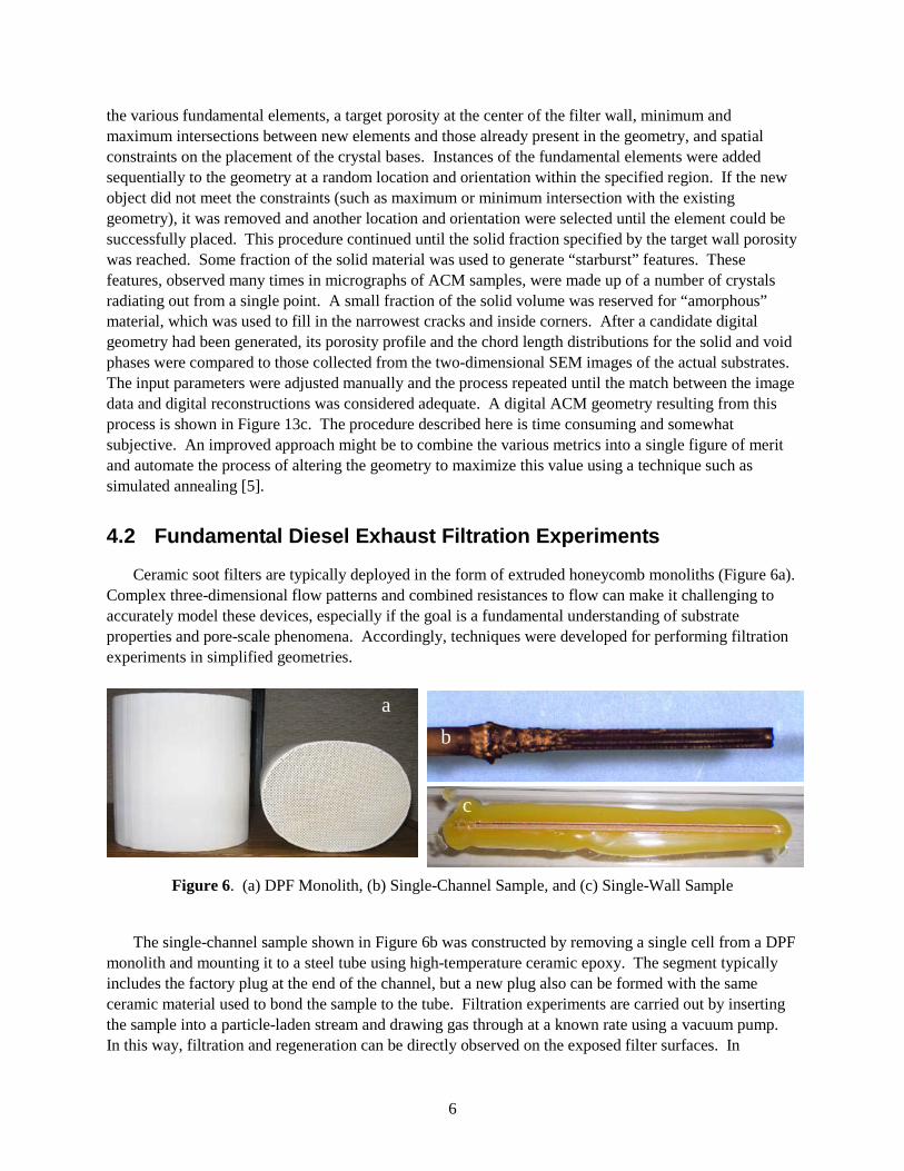
Ceramic soot filters are typically deployed in the form of extruded honeycomb monoliths (Figure 6a). Complex three-dimensional flow patterns and combined resistances to flow can make it challenging to accurately model these devices, especially if the goal is a fundamental understanding of substrate properties and pore-scale phenomena. Accordingly, techniques were developed for performing filtration experiments in simplified geometries.
Figure 6. (a) DPF Monolith, (b) Single-Channel Sample, and (c) Single-Wall Sample
The single-channel sample shown in Figure 6b was constructed by removing a single cell from a DPF
monolith and mounting it to a steel tube using high-temperature ceramic epoxy. The segment typically includes the factory plug at the end of the channel, but a new plug also can be formed with the same ceramic material used to bond the sample to the tube. Filtration experiments are carried out by inserting the sample into a particle-laden stream and drawing gas through at a known rate using a vacuum pump. In this way, filtration and regeneration can be directly observed on the exposed filter surfaces. In
a b
c
7
addition, pressure drop may be measured during filtration in such a way that the only significant resistances to flow are those of the soot cake and porous filter wall. Resistance to flow in the internal channel is usually minor, since the length of the sample is much shorter than the length in a full monolith. Multiple samples may be loaded or regenerated side-by-side in an exhaust stream in order to provide direct comparisons
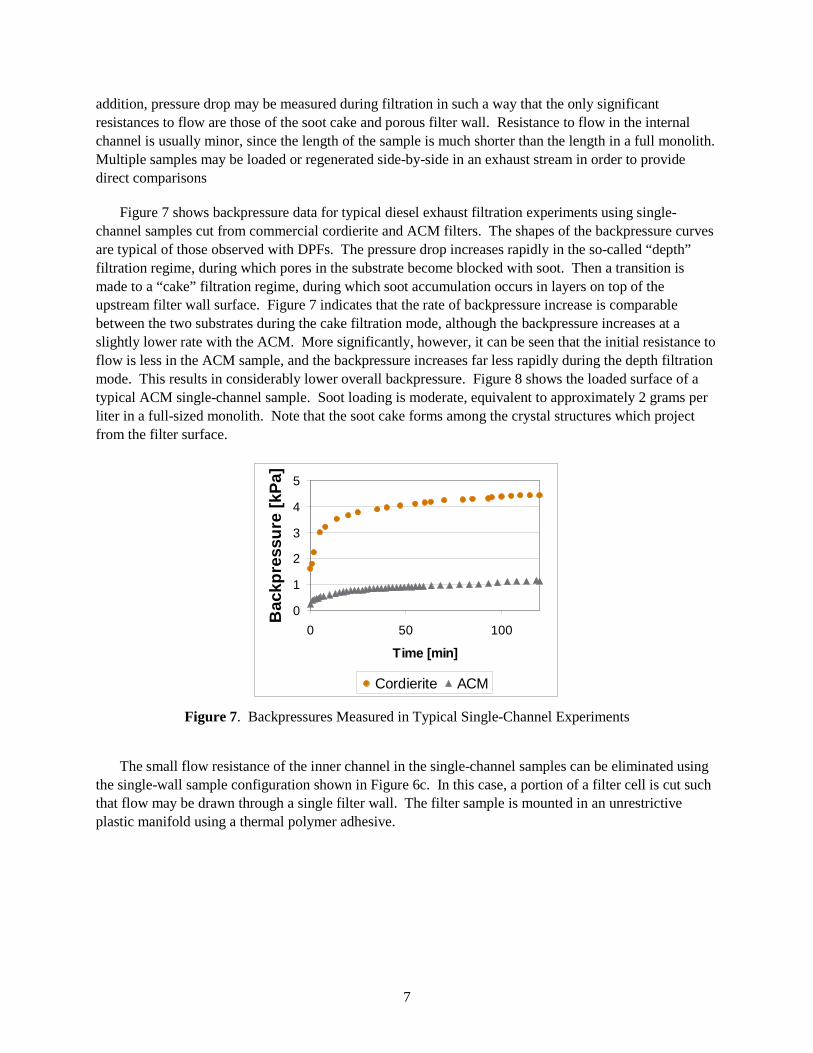
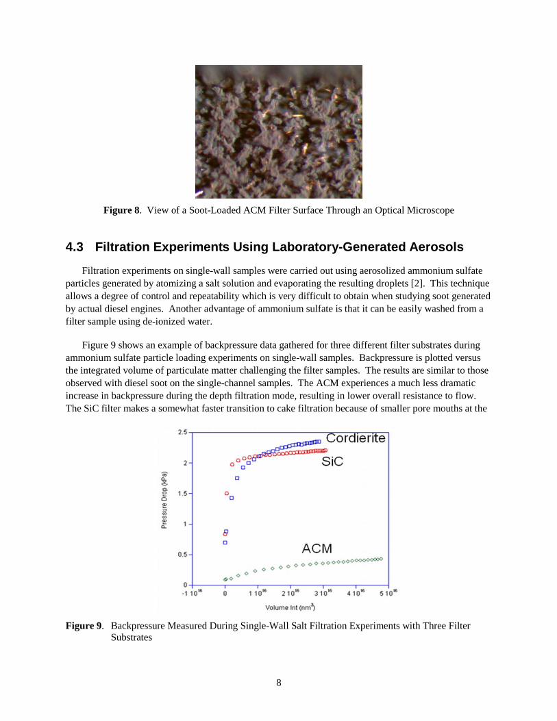
Figure 7 shows backpressure data for typical diesel exhaust filtration experiments using single-channel samples cut from commercial cordierite and ACM filters. The shapes of the backpressure curves are typical of those observed with DPFs. The pressure drop increases rapidly in the so-called “depth” filtration regime, during which pores in the substrate become blocked with soot. Then a transition is made to a “cake” filtration regime, during which soot accumulation occurs in layers on top of the upstream filter wall surface. Figure 7 indicates that the rate of backpressure increase is comparable between the two substrates during the cake filtration mode, although the backpressure increases at a slightly lower rate with the ACM. More significantly, however, it can be seen that the initial resistance to flow is less in the ACM sample, and the backpressure increases far less rapidly during the depth filtration mode. This results in considerably lower overall backpressure. Figure 8 shows the loaded surface of a typical ACM single-channel sample. Soot loading is moderate, equivalent to approximately 2 grams per liter in a full-sized monolith. Note that the soot cake forms among the crystal structures which project from the filter surface.
0
1
2
3
4
5
0 50 100
Time [min]
Bac
kpre
ssur
e [k
Pa]
Cordierite ACM
Figure 7. Backpressures Measured in Typical Single-Channel Experiments
The small flow resistance of the inner channel in the single-channel samples can be eliminated using
the single-wall sample configuration shown in Figure 6c. In this case, a portion of a filter cell is cut such that flow may be drawn through a single filter wall. The filter sample is mounted in an unrestrictive plastic manifold using a thermal polymer adhesive.
8
Figure 8. View of a Soot-Loaded ACM Filter Surface Through an Optical Microscope
4.3 Filtration Experiments Using Laboratory-Generated Aerosols
Filtration experiments on single-wall samples were carried out using aerosolized ammonium sulfate particles generated by atomizing a salt solution and evaporating the resulting droplets [2]. This technique allows a degree of control and repeatability which is very difficult to obtain when studying soot generated by actual diesel engines. Another advantage of ammonium sulfate is that it can be easily washed from a filter sample using de-ionized water.
Figure 9 shows an example of backpressure data gathered for three different filter substrates during ammonium sulfate particle loading experiments on single-wall samples. Backpressure is plotted versus the integrated volume of particulate matter challenging the filter samples. The results are similar to those observed with diesel soot on the single-channel samples. The ACM experiences a much less dramatic increase in backpressure during the depth filtration mode, resulting in lower overall resistance to flow. The SiC filter makes a somewhat faster transition to cake filtration because of smaller pore mouths at the
Figure 9. Backpressure Measured During Single-Wall Salt Filtration Experiments with Three Filter
Substrates
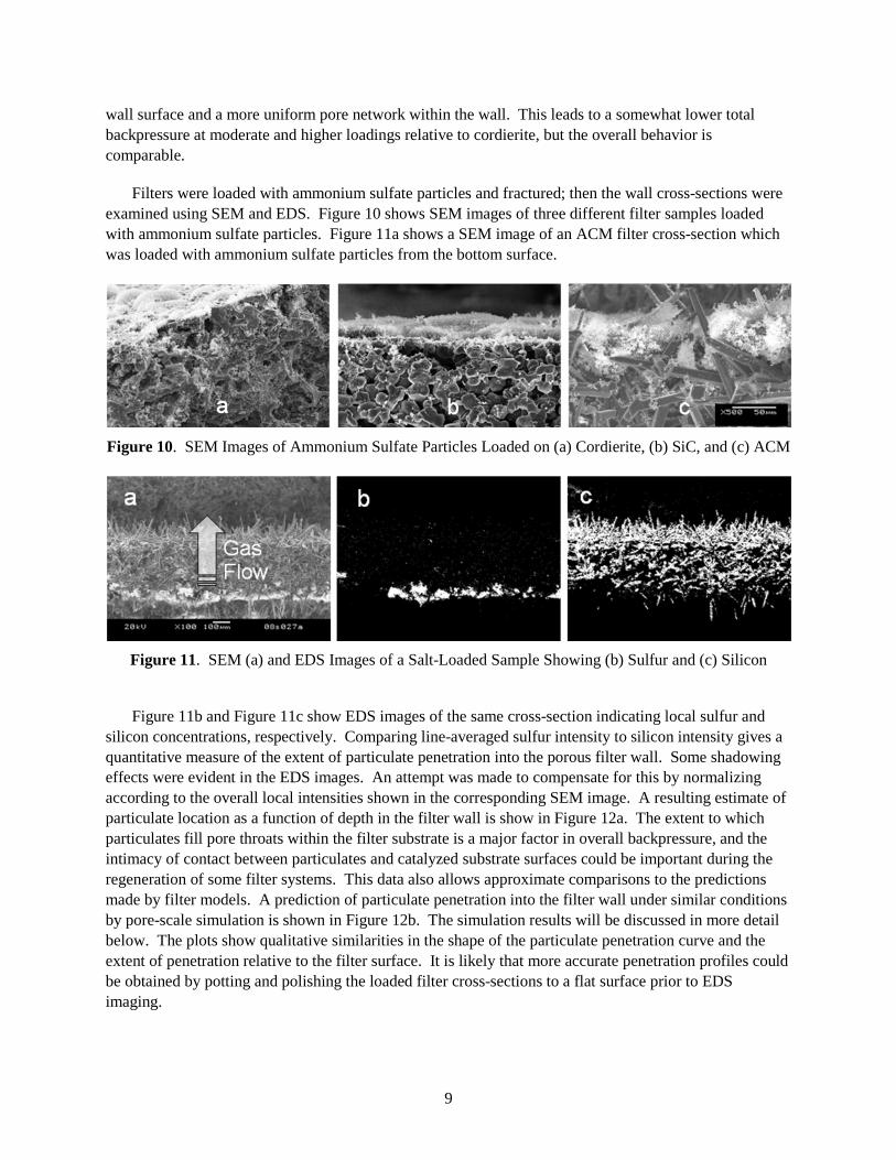
9
wall surface and a more uniform pore network within the wall. This leads to a somewhat lower total backpressure at moderate and higher loadings relative to cordierite, but the overall behavior is comparable.
Filters were loaded with ammonium sulfate particles and fractured; then the wall cross-sections were examined using SEM and EDS. Figure 10 shows SEM images of three different filter samples loaded with ammonium sulfate particles. Figure 11a shows a SEM image of an ACM filter cross-section which was loaded with ammonium sulfate particles from the bottom surface.
Figure 10. SEM Images of Ammonium Sulfate Particles Loaded on (a) Cordierite, (b) SiC, and (c) ACM
Figure 11. SEM (a) and EDS Images of a Salt-Loaded Sample Showing (b) Sulfur and (c) Silicon
Figure 11b and Figure 11c show EDS images of the same cross-section indicating local sulfur and
silicon concentrations, respectively. Comparing line-averaged sulfur intensity to silicon intensity gives a quantitative measure of the extent of particulate penetration into the porous filter wall. Some shadowing effects were evident in the EDS images. An attempt was made to compensate for this by normalizing according to the overall local intensities shown in the corresponding SEM image. A resulting estimate of particulate location as a function of depth in the filter wall is show in Figure 12a. The extent to which particulates fill pore throats within the filter substrate is a major factor in overall backpressure, and the intimacy of contact between particulates and catalyzed substrate surfaces could be important during the regeneration of some filter systems. This data also allows approximate comparisons to the predictions made by filter models. A prediction of particulate penetration into the filter wall under similar conditions by pore-scale simulation is shown in Figure 12b. The simulation results will be discussed in more detail below. The plots show qualitative similarities in the shape of the particulate penetration curve and the extent of penetration relative to the filter surface. It is likely that more accurate penetration profiles could be obtained by potting and polishing the loaded filter cross-sections to a flat surface prior to EDS imaging.
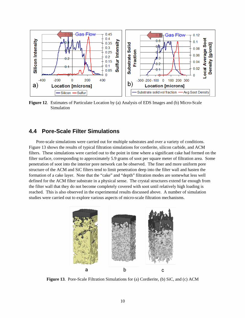
10
Figure 12. Estimates of Particulate Location by (a) Analysis of EDS Images and (b) Micro-Scale
Simulation
4.4 Pore-Scale Filter Simulations
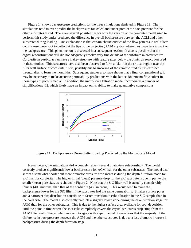
Pore-scale simulations were carried out for multiple substrates and over a variety of conditions. Figure 13 shows the results of typical filtration simulations for cordierite, silicon carbide, and ACM filters. These simulations were carried out to the point in time where a significant cake had formed on the filter surface, corresponding to approximately 5.9 grams of soot per square meter of filtration area. Some penetration of soot into the interior pore network can be observed. The finer and more uniform pore structure of the ACM and SiC filters tend to limit penetration deep into the filter wall and hasten the formation of a cake layer. Note that the “cake” and “depth” filtration modes are somewhat less well defined for the ACM filter substrate in a physical sense. The crystal structures extend far enough from the filter wall that they do not become completely covered with soot until relatively high loading is reached. This is also observed in the experimental results discussed above. A number of simulation studies were carried out to explore various aspects of micro-scale filtration mechanisms.
Figure 13. Pore-Scale Filtration Simulations for (a) Cordierite, (b) SiC, and (c) ACM
11
Figure 14 shows backpressure predictions for the three simulations depicted in Figure 13. The simulations tend to over-predict the backpressure for ACM and under-predict the backpressure for the other substrates tested. There are several possibilities for why the version of the computer model used to perform this study under-predicted the difference in overall backpressure between the ACM and other substrates during loading. One explanation is that certain characteristics of the flow patterns in real filters could cause more soot to collect at the tips of the projecting ACM crystals where they have less impact on the backpressure. This phenomenon is discussed in a subsequent section. It also is possible that the digital reconstructions still did not adequately resolve very fine details of the substrate microstructures. Cordierite in particular can have a flakey structure with feature sizes below the 3 micron resolution used in these studies. Thin structures have also been observed to form a ‘skin’ in the critical region near the filter wall surface of cordierite filters, possibly due to smearing of the ceramic mud as it is extruded through dies to form the monoliths. Subsequent studies also have shown that a finer computational grid may be necessary to make accurate permeability predictions with the lattice-Boltzmann flow solver in these types of porous media. In addition, the micro-scale filtration model incorporates a number of simplifications [1], which likely have an impact on its ability to make quantitative comparisons.
0
0.5
1
1.5
2
2.5
3
3.5
0 1 2 3 4 5 6
Bac
k-pr
essu
re [k
Pa]
Loading [g/m2]
Cordierite
SiC
ACM
Figure 14. Backpressures During Filter Loading Predicted by the Micro-Scale Model
Nevertheless, the simulations did accurately reflect several qualitative relationships. The model
correctly predicts significantly lower backpressure for ACM than for the other substrates. The model also shows a somewhat shorter but more dramatic pressure drop increase during the depth filtration mode for SiC than for cordierite. The higher initial (clean) pressure drop for the SiC substrate is due in part to the smaller mean pore size, as is shown in Figure 2. Note that the SiC filter wall is actually considerably thinner (400 microns) than that of the cordierite (480 microns). This would tend to make the backpressure lower for the SiC filter if the substrates had the same permeability. Smaller surface pores and a narrower size distribution contribute to faster transition to cake filtration in the SiC sample than in the cordierite. The model also correctly predicts a slightly lower slope during the cake filtration stage for ACM than for the other substrates. This is due to the higher surface area available for soot deposition until the point in time where the soot cake completely covers the crystal structures projecting from the ACM filter wall. The simulations seem to agree with experimental observations that the majority of the difference in backpressure between the ACM and the other substrates is due to a less dramatic increase in backpressure during the depth filtration stage.
12
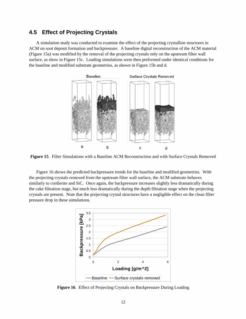
4.5 Effect of Projecting Crystals
A simulation study was conducted to examine the effect of the projecting crystalline structures in ACM on soot deposit formation and backpressure. A baseline digital reconstruction of the ACM material (Figure 15a) was modified by the removal of the projecting crystals only on the upstream filter wall surface, as show in Figure 15c. Loading simulations were then preformed under identical conditions for the baseline and modified substrate geometries, as shown in Figure 15b and d.
Figure 15. Filter Simulations with a Baseline ACM Reconstruction and with Surface Crystals Removed
Figure 16 shows the predicted backpressure trends for the baseline and modified geometries. With
the projecting crystals removed from the upstream filter wall surface, the ACM substrate behaves similarly to cordierite and SiC. Once again, the backpressure increases slightly less dramatically during the cake filtration stage, but much less dramatically during the depth filtration stage when the projecting crystals are present. Note that the projecting crystal structures have a negligible effect on the clean filter pressure drop in these simulations.
0
0.5
1
1.5
2
2.5
3
3.5
0 2 4 6
Loading [g/m^2]
Bac
kpre
ssur
e [k
Pa]
Baseline Surface crystals removed
Figure 16. Effect of Projecting Crystals on Backpressure During Loading
13
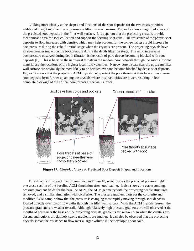
Looking more closely at the shapes and locations of the soot deposits for the two cases provides additional insight into the role of pore-scale filtration mechanisms. Figure 17 shows magnified views of the predicted soot deposits at the filter wall surface. It is apparent that the projecting crystals provide more surface area for soot collection and support the forming soot cake. The resistance of the porous soot deposits to flow increases with density, which may help account for the somewhat less rapid increase in backpressure during the cake filtration stage when the crystals are present. The projecting crystals have an even greater impact on the backpressure during the depth filtration stage. The rapid increase in backpressure observed during depth filtration is the result of pore throats becoming blocked with soot deposits [6]. This is because the narrowest throats in the random pore network through the solid substrate material are the locations of the highest local fluid velocities. Narrow pore throats near the upstream filter wall surface are obviously the most likely to be bridged over and become blocked by dense soot deposits. Figure 17 shows that the projecting ACM crystals help protect the pore throats at their bases. Less dense soot deposits form further up among the crystals where local velocities are lower, resulting in less complete blockage of the critical pore throats at the wall surface.
Figure 17. Close-Up Views of Predicted Soot Deposit Shapes and Locations
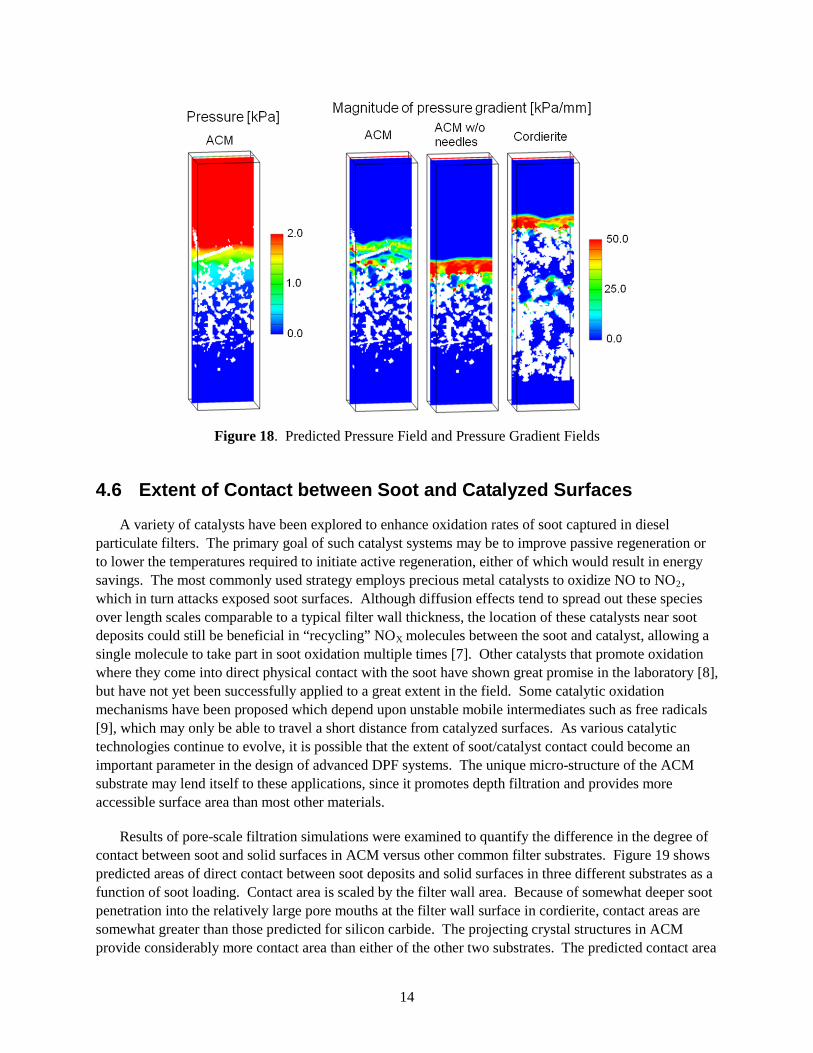
This effect is illustrated in a different way in Figure 18, which shows the predicted pressure field in
one cross-section of the baseline ACM simulation after soot loading. It also shows the corresponding pressure gradient fields for the baseline ACM, the ACM geometry with the projecting needle structures removed, and a similar simulation with cordierite. The pressure gradient plots for the cordierite and modified ACM sample show that the pressure is changing most rapidly moving through soot deposits located directly over major flow paths through the filter wall surface. With the ACM crystals present, the pressure gradients are weaker overall. Although relatively high pressure gradients are still observed at the mouths of pores near the bases of the projecting crystals, gradients are weaker than when the crystals are absent, and regions of relatively strong gradients are smaller. It can also be observed that the projecting crystals spread the resistance to flow over a larger volume in the developing soot cake.
14
Figure 18. Predicted Pressure Field and Pressure Gradient Fields
4.6 Extent of Contact between Soot and Catalyzed Surfaces
A variety of catalysts have been explored to enhance oxidation rates of soot captured in diesel particulate filters. The primary goal of such catalyst systems may be to improve passive regeneration or to lower the temperatures required to initiate active regeneration, either of which would result in energy savings. The most commonly used strategy employs precious metal catalysts to oxidize NO to NO2, which in turn attacks exposed soot surfaces. Although diffusion effects tend to spread out these species over length scales comparable to a typical filter wall thickness, the location of these catalysts near soot deposits could still be beneficial in “recycling” NOX
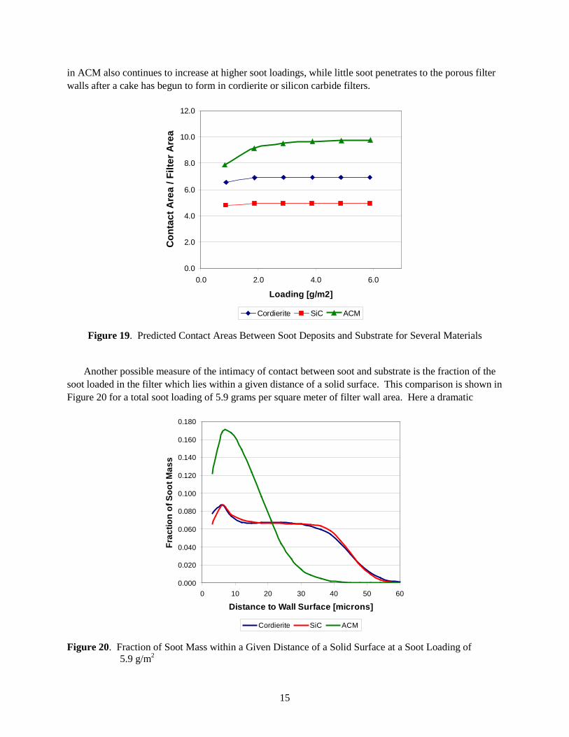
Results of pore-scale filtration simulations were examined to quantify the difference in the degree of contact between soot and solid surfaces in ACM versus other common filter substrates.
molecules between the soot and catalyst, allowing a single molecule to take part in soot oxidation multiple times [7]. Other catalysts that promote oxidation where they come into direct physical contact with the soot have shown great promise in the laboratory [8], but have not yet been successfully applied to a great extent in the field. Some catalytic oxidation mechanisms have been proposed which depend upon unstable mobile intermediates such as free radicals [9], which may only be able to travel a short distance from catalyzed surfaces. As various catalytic technologies continue to evolve, it is possible that the extent of soot/catalyst contact could become an important parameter in the design of advanced DPF systems. The unique micro-structure of the ACM substrate may lend itself to these applications, since it promotes depth filtration and provides more accessible surface area than most other materials.
Figure 19 shows predicted areas of direct contact between soot deposits and solid surfaces in three different substrates as a function of soot loading. Contact area is scaled by the filter wall area. Because of somewhat deeper soot penetration into the relatively large pore mouths at the filter wall surface in cordierite, contact areas are somewhat greater than those predicted for silicon carbide. The projecting crystal structures in ACM provide considerably more contact area than either of the other two substrates. The predicted contact area
15
in ACM also continues to increase at higher soot loadings, while little soot penetrates to the porous filter walls after a cake has begun to form in cordierite or silicon carbide filters.
0.0
2.0
4.0
6.0
8.0
10.0
12.0
0.0 2.0 4.0 6.0
Loading [g/m2]
Con
tact
Are
a / F
ilter
Are
a
Cordierite SiC ACM
Figure 19. Predicted Contact Areas Between Soot Deposits and Substrate for Several Materials
Another possible measure of the intimacy of contact between soot and substrate is the fraction of the
soot loaded in the filter which lies within a given distance of a solid surface. This comparison is shown in Figure 20 for a total soot loading of 5.9 grams per square meter of filter wall area. Here a dramatic
0.000
0.020
0.040
0.060
0.080
0.100
0.120
0.140
0.160
0.180
0 10 20 30 40 50 60
Distance to Wall Surface [microns]
Frac
tion
of S
oot M
ass
Cordierite SiC ACM
Figure 20. Fraction of Soot Mass within a Given Distance of a Solid Surface at a Soot Loading of 5.9 g/m2
16
difference is apparent between ACM and the other substrates examined. Again, because of the projecting crystal structures in ACM, a much higher fraction of the loaded soot is in close proximity (10 to 15 microns) to a solid surface. This may be a more interesting metric for postulated catalytic mechanisms which involve short-lived mobile intermediates.
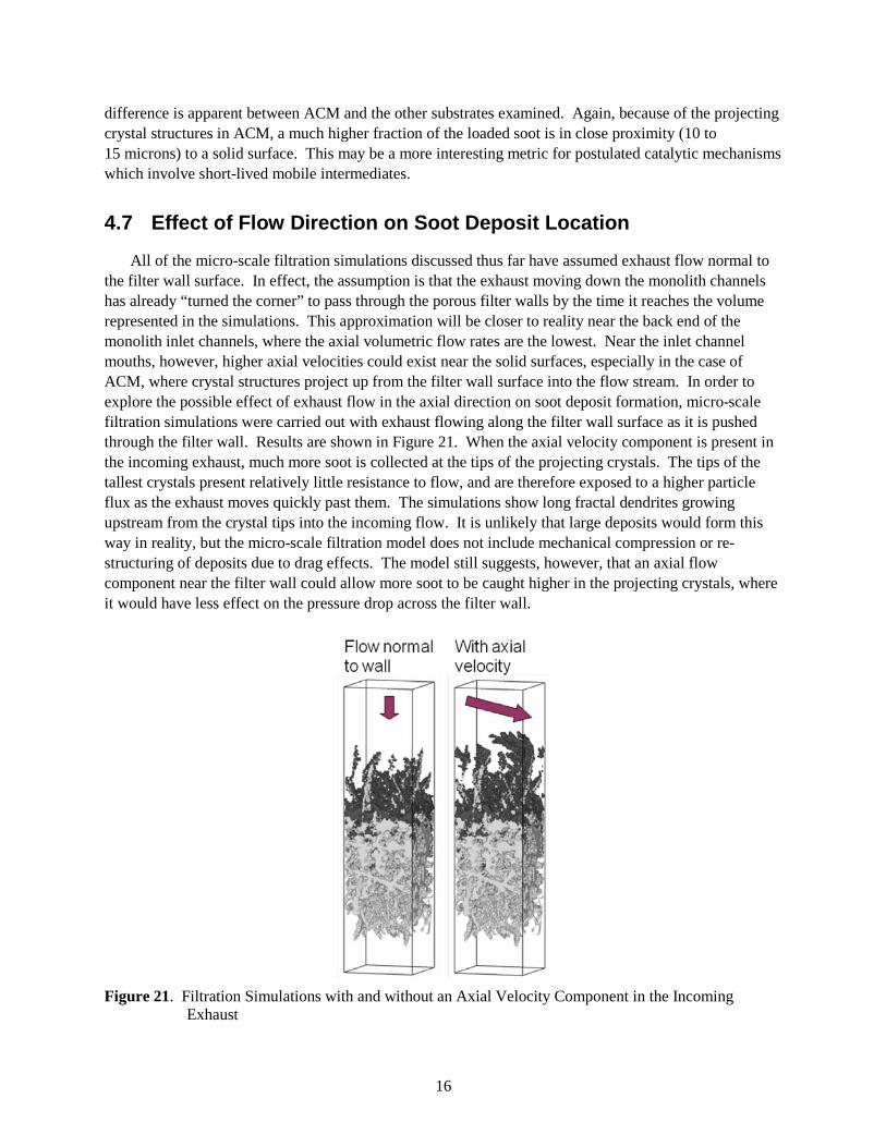
4.7 Effect of Flow Direction on Soot Deposit Location
All of the micro-scale filtration simulations discussed thus far have assumed exhaust flow normal to the filter wall surface. In effect, the assumption is that the exhaust moving down the monolith channels has already “turned the corner” to pass through the porous filter walls by the time it reaches the volume represented in the simulations. This approximation will be closer to reality near the back end of the monolith inlet channels, where the axial volumetric flow rates are the lowest. Near the inlet channel mouths, however, higher axial velocities could exist near the solid surfaces, especially in the case of ACM, where crystal structures project up from the filter wall surface into the flow stream. In order to explore the possible effect of exhaust flow in the axial direction on soot deposit formation, micro-scale filtration simulations were carried out with exhaust flowing along the filter wall surface as it is pushed through the filter wall. Results are shown in Figure 21. When the axial velocity component is present in the incoming exhaust, much more soot is collected at the tips of the projecting crystals. The tips of the tallest crystals present relatively little resistance to flow, and are therefore exposed to a higher particle flux as the exhaust moves quickly past them. The simulations show long fractal dendrites growing upstream from the crystal tips into the incoming flow. It is unlikely that large deposits would form this way in reality, but the micro-scale filtration model does not include mechanical compression or re-structuring of deposits due to drag effects. The model still suggests, however, that an axial flow component near the filter wall could allow more soot to be caught higher in the projecting crystals, where it would have less effect on the pressure drop across the filter wall.
Figure 21. Filtration Simulations with and without an Axial Velocity Component in the Incoming
Exhaust
17
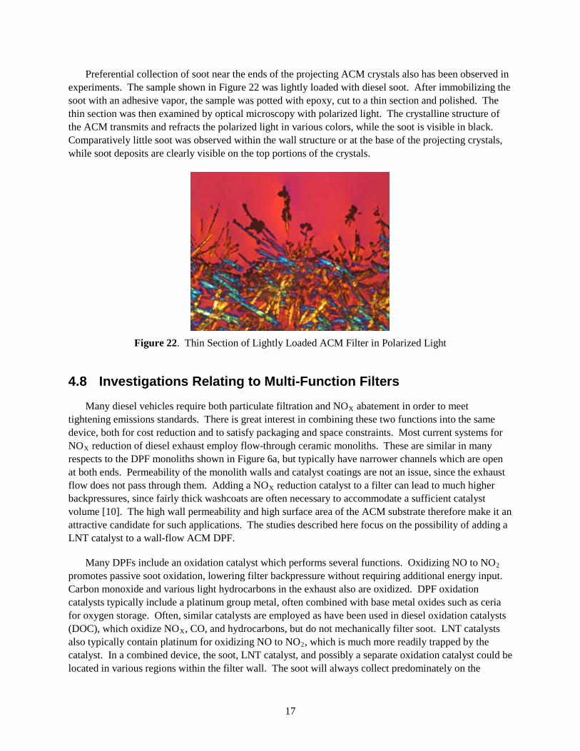
Preferential collection of soot near the ends of the projecting ACM crystals also has been observed in experiments. The sample shown in Figure 22 was lightly loaded with diesel soot. After immobilizing the soot with an adhesive vapor, the sample was potted with epoxy, cut to a thin section and polished. The thin section was then examined by optical microscopy with polarized light. The crystalline structure of the ACM transmits and refracts the polarized light in various colors, while the soot is visible in black. Comparatively little soot was observed within the wall structure or at the base of the projecting crystals, while soot deposits are clearly visible on the top portions of the crystals.
Figure 22. Thin Section of Lightly Loaded ACM Filter in Polarized Light
4.8 Investigations Relating to Multi-Function Filters
Many diesel vehicles require both particulate filtration and NOX abatement in order to meet tightening emissions standards. There is great interest in combining these two functions into the same device, both for cost reduction and to satisfy packaging and space constraints. Most current systems for NOX
Figure 6 reduction of diesel exhaust employ flow-through ceramic monoliths. These are similar in many
respects to the DPF monoliths shown in a, but typically have narrower channels which are open at both ends. Permeability of the monolith walls and catalyst coatings are not an issue, since the exhaust flow does not pass through them. Adding a NOX
Many DPFs include an oxidation catalyst which performs several functions. Oxidizing NO to NO
reduction catalyst to a filter can lead to much higher backpressures, since fairly thick washcoats are often necessary to accommodate a sufficient catalyst volume [10]. The high wall permeability and high surface area of the ACM substrate therefore make it an attractive candidate for such applications. The studies described here focus on the possibility of adding a LNT catalyst to a wall-flow ACM DPF.
2 promotes passive soot oxidation, lowering filter backpressure without requiring additional energy input. Carbon monoxide and various light hydrocarbons in the exhaust also are oxidized. DPF oxidation catalysts typically include a platinum group metal, often combined with base metal oxides such as ceria for oxygen storage. Often, similar catalysts are employed as have been used in diesel oxidation catalysts (DOC), which oxidize NOX, CO, and hydrocarbons, but do not mechanically filter soot. LNT catalysts also typically contain platinum for oxidizing NO to NO2, which is much more readily trapped by the catalyst. In a combined device, the soot, LNT catalyst, and possibly a separate oxidation catalyst could be located in various regions within the filter wall. The soot will always collect predominately on the
18
upstream filter wall surface, but the catalysts could be coated on either or both sides of the filter walls, and techniques exist for placing very thin coatings of oxidation catalysts throughout the entire wall thickness. Flow patterns within a wall-flow DPF are different enough from those in a flow-through LNT that concerns have also been raised that not all of the catalyst volume might have equal exposure to the exhaust, leading to less efficient use of the catalyst. This has been suggested by data from early attempts to combine DPF and selective catalytic reduction functionality in a wall-flow device [11].
A number of fundamental questions are therefore raised by the prospect of combining LNT and DPF functionality in the same device. These include:
1. What is the performance difference between “flow-through” versus “wall-flow” configurations?
2. Is there an advantage of an additional oxidation catalyst upstream versus uniformly dispersed throughout the wall?
3. What is the impact of NOX
4. Does reduction of NO
adsorption on passive soot oxidation rates?
2 to NO by soot oxidation inhibit rates of NOX
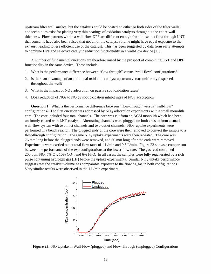
Question 1: What is the performance difference between “flow-through” versus “wall-flow” configurations? The first question was addressed by NO
adsorption?
X adsorption experiments with a small monolith core. The core included four total channels. The core was cut from an ACM monolith which had been uniformly coated with LNT catalyst. Alternating channels were plugged on both ends to form a small wall-flow system with two inlet channels and two outlet channels. NOX uptake experiments were performed in a bench reactor. The plugged ends of the core were then removed to convert the sample to a flow-through configuration. The same NOX
Figure 23
uptake experiments were then repeated. The core was 76 mm long before the plugged ends were removed, and 60 mm long after the ends were removed. Experiments were carried out at total flow rates of 1 L/min and 0.5 L/min. shows a comparison between the performance of the two configurations at the lower flow rate. The gas feed contained 200 ppm NO, 5% O2, 10% CO2, and 6% H2O. In all cases, the samples were fully regenerated by a rich pulse containing hydrogen gas (H2) before the uptake experiments. Similar NOX uptake performance suggests that the catalyst volume has comparable exposure to the flowing gas in both configurations. Very similar results were observed in the 1 L/min experiment.
Figure 23. NO Uptake in Wall-Flow (plugged) and Flow-Through (unplugged) Configurations
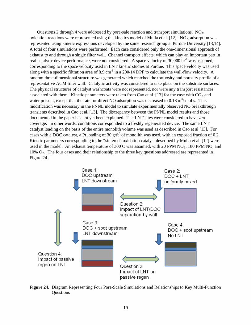
19
Questions 2 through 4 were addressed by pore-sale reaction and transport simulations. NOX oxidation reactions were represented using the kinetics model of Mulla et al. [12]. NOX adsorption was represented using kinetic expressions developed by the same research group at Purdue University [13,14]. A total of four simulations were performed. Each case considered only the one-dimensional approach of exhaust to and through a single filter wall. Channel transport effects, which can play an important part in real catalytic device performance, were not considered. A space velocity of 30,000 hr-1 was assumed, corresponding to the space velocity used in LNT kinetic studies at Purdue. This space velocity was used along with a specific filtration area of 8.9 cm-1 in a 200/14 DPF to calculate the wall-flow velocity. A random three-dimensional structure was generated which matched the tortuosity and porosity profile of a representative ACM filter wall. Catalytic activity was considered to take place on the substrate surfaces. The physical structures of catalyst washcoats were not represented, nor were any transport resistances associated with them. Kinetic parameters were taken from Cao et al. [13] for the case with CO2 and water present, except that the rate for direct NO adsorption was decreased to 0.13 m3/ mol s. This modification was necessary in the PNNL model to simulate experimentally observed NO breakthrough transients described in Cao et al. [13]. The discrepancy between the PNNL model results and those documented in the paper has not yet been explained. The LNT sites were considered to have zero coverage. In other words, conditions corresponded to a freshly regenerated device. The same LNT catalyst loading on the basis of the entire monolith volume was used as described in Cao et al [13]. For cases with a DOC catalyst, a Pt loading of 30 g/ft3 of monolith was used, with an exposed fraction of 0.2. Kinetic parameters corresponding to the “sintered” oxidation catalyst described by Mulla et al. [12] were used in the model. An exhaust temperature of 300 C was assumed, with 20 PPM NO2, 180 PPM NO, and 10% O2
Figure 24. The four cases and their relationship to the three key questions addressed are represented in
.
Figure 24. Diagram Representing Four Pore-Scale Simulations and Relationships to Key Multi-Function
Questions
20
Case 1 involved separate DOC and LNT catalyst layers, the former on the upstream filter wall face, and the latter on the downstream face. Case 2 was identical to Case 1, except that the LNT and DOC catalysts were uniformly mixed throughout the entire filter wall. Case 3 was similar to Case 1 with the addition of a soot loading of 5.9 g/m2
Table 1 on the upstream wall surface. Case 4 was similar to Case 3 with the
omission of the LNT catalyst on the downstream wall surface. shows predicted NOX
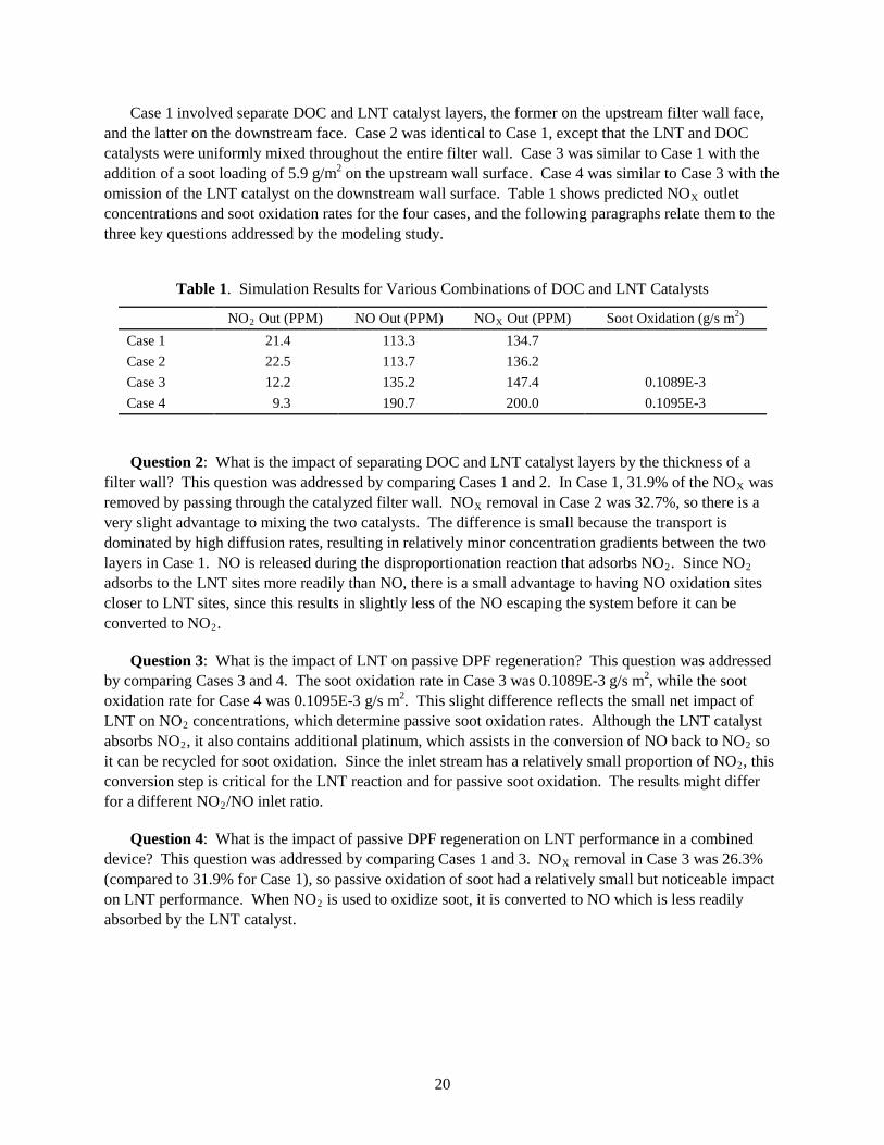
Table 1. Simulation Results for Various Combinations of DOC and LNT Catalysts
outlet concentrations and soot oxidation rates for the four cases, and the following paragraphs relate them to the three key questions addressed by the modeling study.
NO2 NO Out (PPM) Out (PPM) NOX Soot Oxidation (g/s m Out (PPM) 2
Case 1 )
21.4 113.3 134.7 Case 2 22.5 113.7 136.2 Case 3 12.2 135.2 147.4 0.1089E-3 Case 4 9.3 190.7 200.0 0.1095E-3
Question 2: What is the impact of separating DOC and LNT catalyst layers by the thickness of a filter wall? This question was addressed by comparing Cases 1 and 2. In Case 1, 31.9% of the NOX was removed by passing through the catalyzed filter wall. NOX removal in Case 2 was 32.7%, so there is a very slight advantage to mixing the two catalysts. The difference is small because the transport is dominated by high diffusion rates, resulting in relatively minor concentration gradients between the two layers in Case 1. NO is released during the disproportionation reaction that adsorbs NO2. Since NO2 adsorbs to the LNT sites more readily than NO, there is a small advantage to having NO oxidation sites closer to LNT sites, since this results in slightly less of the NO escaping the system before it can be converted to NO2
Question 3: What is the impact of LNT on passive DPF regeneration? This question was addressed by comparing Cases 3 and 4. The soot oxidation rate in Case 3 was 0.1089E-3 g/s m
.
2, while the soot oxidation rate for Case 4 was 0.1095E-3 g/s m2. This slight difference reflects the small net impact of LNT on NO2 concentrations, which determine passive soot oxidation rates. Although the LNT catalyst absorbs NO2, it also contains additional platinum, which assists in the conversion of NO back to NO2 so it can be recycled for soot oxidation. Since the inlet stream has a relatively small proportion of NO2, this conversion step is critical for the LNT reaction and for passive soot oxidation. The results might differ for a different NO2
Question 4: What is the impact of passive DPF regeneration on LNT performance in a combined device? This question was addressed by comparing Cases 1 and 3. NO
/NO inlet ratio.
X removal in Case 3 was 26.3% (compared to 31.9% for Case 1), so passive oxidation of soot had a relatively small but noticeable impact on LNT performance. When NO2
is used to oxidize soot, it is converted to NO which is less readily absorbed by the LNT catalyst.
21
5.0 Conclusions
PNNL and its CRADA partners at Dow Automotive Systems and The Dow Chemical Company have carried out a program to promote the development of fuel efficient diesel particulate filters and next-generation multi-function devices by studying fundamental filtration and transport phenomena. The unique microstructure of the ACM substrate was characterized by mercury porosimetry, microscopy, and image analysis, allowing three-dimensional digital reconstructions for micro-scale flow and transport simulations. Fundamental filtration studies were carried out using small filter samples which eliminate some of the complexity of full filter monoliths. Filtration experiments with diesel soot and with aerosolized salt particles both indicated much lower backpressures with ACM than with other common substrates. SEM images show that filter cakes form among the crystal structures which extend from the ACM filter wall surfaces. EDS images allow estimates of the degree of particulate penetration into the filter wall, which appears to be greater for ACM than for other common DPF substrates.
Pore-scale filtration simulations accurately reflect several qualitative aspects of filtration behavior. The simulations predict higher pressure drops for silicon carbide and cordierite than ACM, although the difference observed in experiments is under-predicted. The simulations suggest that most of the difference in backpressure between ACM and the other substrates is due to a less dramatic increase in pressure drop during the depth filtration stage. Close examination of simulation results suggests that the crystal structures which project from the ACM filter wall play important roles in keeping the back-pressure low by protecting pore mouths at their bases from being completely blocked and by supporting the soot deposits which form among them, leading to more open structures with higher overall permeability. Simulations also indicate that ACM offers considerably more surface area for contact between a catalyzed filter and captured soot. Some experiments suggested that a significant portion of the soot captured in ACM filters is initially deposited near the tips of the projecting crystal structures. Simulations indicate that this may be due in part to the axial flow of exhaust along the length of the filter channels.
Fundamental experiments and modeling studies were carried out to answer several key questions regarding proposed multi-function devices, which could remove soot, hydrocarbons, carbon monoxide, and oxides of nitrogen from diesel exhaust. Experiments suggested that wall-flow LNT devices can perform similarly to flow-through devices with the same amount of catalyst. Transport and reaction simulations suggest that there may not be great advantages to separating LNT and oxidation catalysts across the filter wall thickness, due to the dominance of diffusion transport. Under the conditions examined, little adverse impact of NOX adsorption on soot oxidation was predicted, since the LNT catalyst also produced a significant amount of NO2 from NO. Passive oxidation of soot, however, was observed to have a noticeable impact on rates of NOX adsorption, since the oxidation reaction converts NO2
Insight gained during this CRADA project has supported Dow Automotive as they commercialized the ACM substrate in the AERIFY
to NO, which is much less readily adsorbed on the LNT catalyst.
TM product line and made strategic decisions concerning the development of new technologies. Over the course of this research project, ACM filters were also successfully deployed on Audi and Peugeot diesel racecars which have between them taken most of the first and second place trophies in the 24 Hours of LeMans and 12 Hours of Sebring races for the past five years. It would not have been possible for any of the diesel vehicles to compete in these traditionally gasoline-dominated events without reliable and effective exhaust particulate filtration. These successes
22
demonstrated not only the performance of automotive diesel engines, but also the efficacy of DPF technology as it was being deployed around the world to meet new emissions standards on consumer vehicles. The experimental and modeling techniques developed over the course of the project are applicable to a wide range of other advanced substrates for exhaust filters and multi-function after-treatment devices.
6.0 Literature Cited
1. Stewart, M., D. Rector, G. Muntean, and G. Maupin, "A mechanistic model for particle deposition in diesel particluate filters using the lattice-Boltzmann technique." In 28th International Cocoa Beach Conference & Exposition on Advanced Ceramics & Composites. 2004. Cocoa Beach, FL, United States: American Ceramic Society, Westerville, OH, United States.
2. Yang, J., M. Stewart, G. Maupin, D. Herling, and A. Zelenyuk, "Single wall diesel particulate filter (DPF) filtration efficiency studies using laboratory generated particles." Chemical Engineering Science, 2009. 64(8): p. 1625-1634.
3. Merkel, G.A., D.M. Beall, D.L. Hickman, and M.J. Vernacotola, "Effects of Mictrostructure and Cell Geometry on Performance of Cordierite Diesel Particulate Filters." SAE Technical Paper Series, 2001. 2001-01-0193.
4. Roberts, A. and S. Torquato, "Chord-distribution functions of three-dimensional random media: Approximate first-passage times of Gaussian processes." PHYSICAL REVIEW E, 1999. 59(5): p. 4953-4963.
5. Talukdar, M.S., O. Torsaeter, and J.J. Howard, "Stochastic reconstruction of chalk samples containing vuggy porosity using a conditional simulated annealing technique." Transport in Porous Media, 2004. 57(1): p. 1-15.
6. Merkel, G.A., W.A. Cutler, T. Tao, A. Chiffey, P. Phillips, M.V. Twigg, and A. Walker, "New cordierite diesel particulate filters for catalyzed and non-catalyzed applications." In 9th Diesel Engine Emissions Reduction Conference. 2003. Newport, Rhode Island.
7. Chatterjee, S., R. Conway, S. Viswanathan, and T. Jacobs, "Diesel Particulate Filter Technology for Low-Temperature and Low-NOx/PM Applications." DEER Conference, 2004, 2004.
8. Southward, B.W.L. and S. Basso, "An Investigation into the NO2-mediated Decoupling of Catalyst to Soot Contact and its Implications for Catalysed DPF Performance." SAE World Congress, 2008. 2008-01-0481.
9. Bokova, M., C. Decarne, E. Abi-Aad, A. Pryakhin, V. Lunin, and A. Aboukais, "Effects of ozone on the catalytic combustion of carbon black." Applied Catalysis B-Environmental, 2004. 54(1): p. 9-17.
10. Cavataio, G., J.W. Girard, and C.K. Lambert, "Cu/Zeolite SCR on High Porosity Particulate Filters: Laboratory and Engine Performance Evaluations." SAE World Congress, 2009. 2009-01-0897.
11. Oladipo, B., O. Bailey, K. Price, N. Balzan, and S. Kaul, "Simplification of Diesel Emission Control System Packaging Using SCR Coated on DPF." In DEER 2008. 2008. Deerborn, MI.
12. Mulla, S.S., N. Chen, L. Cumaranatunge, G.E. Blau, D.Y. Zemlyanov, W.N. Delgass, W.S. Epling, and F.H. Ribeiro, "Reaction of NO and O-2 to NO2 on Pt: Kinetics and catalyst deactivation." Journal Of Catalysis, 2006. 241(2): p. 389-399.
13. Cao, L., J.L. Ratts, A. Yezerets, N.W. Currier, J.M. Caruthers, F.H. Ribeiro, and W.N. Delgass, "Kinetic Modeling of NOx Storage/Reduction on Pt/BaO/Al2O3 Monolith Catalysts." Industrial & Engineering Chemistry Research, 2008. 47(23): p. 9006-9017.
23
14. Kromer, B.R., L. Cao, L. Cumaranatunge, S.S. Mulla, J.L. Ratts, A. Yezerets, N.W. Currier, F.H. Ribeiro, W.N. Delgass, and J.M. Caruthers, "Modeling of NO oxidation and NOx storage on Pt/BaO/Al2O3 NOx traps." Catalysis Today, 2008. 136: p. 93-103.
7.0 Reports/Publications
1. Gallant, T.R., M.L. Stewart, D.H. Kim, G.D. Maupin. “Diesel Soot Filter Characterization and Modeling for Advanced Substrates” in DOE EERE 2009 Advanced Combustion Engine Research and Development Annual Progress Report. December 2009.
2. Saenz, N., H. Dillon, S. Carlson, and G. Maupin. “Advanced Metallographic Techniques Applied to Diesel Particulate Filters.” Microscopy Today, 2007: 15(5): p. 44.
8.0 Presentations
1. Gallant, T.R. “Diesel Soot Filter Characterization and Modeling for Advanced Substrates.” Presentation at the DOE Hydrogen Program and Vehicle Technologies Program Annual Merit Review and Peer Evaluation Meeting, Arlington, VA, May 20, 2009.
2. Gallant, T.R. “Diesel Soot Filter Characterization and Modeling for Advanced Substrates.” Presentation at the DOE Hydrogen Program and Vehicle Technologies Program Annual Merit Review and Peer Evaluation Meeting, Bethesda, MD, Feb. 27, 2008.
3. Gallant, T.R. “Diesel Soot Filter Characterization and Modeling for Advanced Substrates.” Presentation at the DOE EERE Semi-Mega Merit Review, Arlington, VA, June 18-19, 2007.
4. M.L. Stewart, Gallant, T.R., G.D. Maupin, H.E. Dillon, D.H. Kim, F. Mao, C. Li, S. Martin, A. Pyzik, and R. Ziebarth. “Fundamental Modeling and Experimental Studies of Acicular Mullite Diesel Particulate Filters.” Diesel Exhaust Emissions Reduction Conference, Dearborn, MI, August 5, 2008.
5. Gallant, T.R. “Experimental Diesel Particulate Filter Capabilities at PNNL.” Diesel Exhaust Emissions Reduction Conference, Detroit, MI, August 24, 2006.
6. Gallant, T.R. “Fuel Efficient Diesel Particulate Filter Modeling and Development.” Presentation at the DOE Merit Review of Advanced Combustion, Emission Control, and Fuels Research, Argonne, IL, May 16, 2006.
7. Gallant, T.R. “Single Channel DPF Experiments to Investigate Soot Cake Structures.” Diesel Exhaust Emissions Reduction Conference, Chicago, IL, August 25, 2005.