Embed Size (px)
Citation preview

1
5995482584 April 2007
FRIGIDAIRE
FREEZER
WITH
ELECTRONIC CONTROLS
SERVICE MANUAL
ELECTROLUX MAJOR APPLIANCES OF NORTH AMERICA
White-Westinghouse

2
ATTENTION!!!This service manual is intended for use by persons having electrical and mechanicaltraining and a level of knowledge of these subjects generally considered acceptable in theappliance repair trade. Electrolux Home Products cannot be responsible, nor assume anyliability, for injury or damage of any kind arising from the use of this manual.
Toavoid personal injuryand/orpropertydamage, it is important thatSafeServicingPractices beobserved. The followingare some limitedexamplesof safe practices:
1. DO NOT attempt a product repair if you have any doubts as to your ability tocomplete it in a safe and satisfactory manner.
2. Before servicing or moving an appliance:
• Remove thepowercord fromtheelectrical outlet, trip the circuit breaker to theOFF position, or remove the fuse.
• Turnoff thegas supply.• Turnoff thewatersupply.
3. Never interfere with the proper operation of any safety device.
4. USE ONLY REPLACEMENT PARTS CATALOGED FOR THIS APPLIANCE.SUBSTITUTIONS MAY DEFEAT COMPLIANCE WITH SAFETYSTANDARDS SET FOR HOME APPLIANCES.
5. GROUNDING: The standard color coding for safety ground wires is GREEN, orGREEN with YELLOW STRIPES. Ground leads are not to be used as currentcarrying conductors. It is EXTREMELY important that the service technicianreestablish all safety grounds prior to completion of service. Failure to do so willcreate a hazard.
6. Prior to returning the product to service, ensure that:
• All electrical connections are correct and secure• Allelectrical leads areproperlydressedand securedawayfromsharpedges,
high-temperaturecomponents,andmovingparts• Allnon-insulatedelectrical terminals,connectors,heaters,etc.areadequately
spaced away from all metal parts and panels• All safety grounds (both internal and external) are correctly and securely
connected• All panels are properly and securely reassembled
SAFE SERVICING PRACTICES - ALL APPLIANCES
2007 Electrolux Major Appliances of North America

3
SAFE SERVICING PRACTICES 2
QUICK REFERENCE SHEET 9
Serial nameplate location 9Chest models 9Upright models 9
Serial number breakdown 9Cold control location 10
Chest models 10User interface location 10
Upright models with deluxe control 10Chest models 10
Electronic control location (Upright models with standard control) 10Electronic module location 11
Chest models 11Upright models with deluxe control 11
Temperature alarm switch and indicator lights location(Upright models with standard control) 11Deluxe control information 12Standard control information 13Sample wiring diagram (Chest freezer) 14System schematic (Chest freezer) 15Installation (Chest freezer) 15Refrigerant charge, and electrical specifications (Chest freezer) 15Temperature control (Chest freezer) 15Performance (Chest freezer) 15Thermistor resistance (Chest freezer) 15Sample wiring diagram (Upright models with deluxe control) 16Sample wiring diagram (Upright models with standard control) 17Specifications (Upright Freezers) 18
Refrigerant charge and electrical 18Defrost control 18Temperature control (Upright models with deluxe control) 18Performance (Upright models with deluxe control) 18Temperature control (Upright models with standard control) 18Performance (Upright models with standard control) 18Thermistor resistance (Upright models with deluxe control) 18
System schematic (Upright freezer) 19Service diagnostic (Upright models with deluxe control) 20Air moment in upright freezers 20
SECTION A - OWNERS GUIDE 21
Product registration 21
Record your model and serial numbers 21Register your product 21
Energy saving ideas 21Important safety instructions 21
For your safety 21Child safety 21Risk of child entrapment 22
Electrical information 22Other precautions 22First steps 22
Installation / freezer placement 22Leveling 23
To level upright units 23To level chest units 23
Door removal (Upright models) 23

4
Lid removal (Chest models) 24Setting the temperature control 24
Cool down period 24Electromechanical temperature control (Chest and some upright models) 24Standard electronic temperature control (Some upright frost free models) 24Deluxe electronic temperature control (Some upright frost free models) 24
Freezer optional features 24Power on light 24Electromechanical temperature alarm(Audible only or audible with warning light) 24Electronic temperature alarm (Some electronic chest models) 25Electronic temperature alarm (Some electronic upright models) 25Slide-out basket (Some upright models) 25Security lock with pop-out key 25Interior light 25Adjustable shelf (Some upright models) 25Slide-aside basket (Chest models) 25Fast freezing shelves (Manual defrost upright models) 25Tilt-out shelf (Some upright models) 25Drop front (Some upright models) 26Basket divider (Some upright models) 26Small item shelf (Some upright models) 26Pizza shelf (Some upright models) 26Chest divider (Some chest models) 26
Examples of chest divider configurations 27Compressor mounted drain pan (Most upright frost free models) 27
Care and cleaning 27Between defrostings 27Defrosting 27
To defrost upright models with defrost drain 27To defrost chest models with defrost drain 27To defrost models without defrost drain 28
Cleaning the inside 28Cleaning the outside 28
Power failure / freezer failure 28Risk of child entrapment 28Vacation and moving tips 29
Short vacations 29Long vacations 29
Moving 29If a power failure occurs 29
Avoid service checklist 30Freezer does not run 30Freezer runs too much or too long 30Interior freezer temperature is too cold 30Interior freezer temperature is too warm 30Freezer external surface temperature is warm 30Louder sound levels whenever freezer is on 30Louder sound levels when compressor comes on 30Popping or cracking sound when compressor comes on 30Bubbling or gurgling sound 31Vibrating or rattling noise 31Moisture forms on inside freezer walls 31Moisture forms on outside freezer walls 31Odors in freezer 31Door/lid will not close 31Light bulb is not on 31

5
Automatic icemaker not working (Some models) 31Compact appliance warranty information 32
SECTION B - ELECTRONIC CONTROLS GUIDE 33
Temperature control 33
Temperature setting 33Extreme freeze 33Display lockout 33Alarm function 34Temperature alarm 34Door/lid ajar alarm 34Power failure 34System error alarm 34Alarm function table 34
SECTION C - ELECTRICAL OPERATION 35
Electrical mechanical control models 35
Compressor circuit 35Alarm function circuit 35Freezer light circuit 35
Standard electronic control models 36Sealed system circuit 36Defrost circuit 36Interior light circuit 36Power on indicator light circuit 37Alarm circuit 37
Deluxe electronic control models 38Electronics module and user interface circuit 38Sealed system circuit 38Defrost circuit 38Interior light circuit 39
SECTION D - REFRIGERATION SYSTEM & SERVICE 40
Safety 40
Soldering 40Refrigeration system 41Refrigerant cycle 42Low or high side leak or undercharge 42Test for refrigerant leaks 42Procedure for checking condenser leaks 43Evacuating and recharging 43
Equipment needed for evacuation & recharging 43Installing evacuation and recharging equipment 44Evacuating system 44Charging the system 44Preparing the charging cylinder 45Final leak test 45
SECTION E - TROUBLESHOOTING CHART(ELECTRICAL MECHANICAL CONTROL MODELS) 46
Compressor does not run 46
Compressor runs continuously, but freezer is not cold 46Compressor runs continuously and the freezer is too cold 46Freezer temperatures do not correspond with temperature control settings 47Frost pattern does not cover evaporator 47Buzzer does not sound when temperature in thefreezer compartment goes above 23° F. 47Buzzer does not turn off when temp alarm button is pushed 47Interior light does not illuminate when door/lid is opened 47

6
SECTION F - TROUBLESHOOTING CHART(STANDARD ELECTRONIC CONTROL MODELS) 48
Compressor and evaporator fan motor do not run 48
Compressor does not run, but the evaporator fan motor does 48Evaporator fan motor does not run, but the compressor operates 48Electronic control display does not illuminate, but the freezer operates 48The electronic control does not respond when the upper or down arrows are pushed 48Interior light does not glow when door is opened 48Compressor runs continuously, but freezer is not cold 48Compressor runs continuously and the freezer is too cold 49Freezer temperatures do not correspond with temperature controlsettings, but the compressor operation is normal 49Freezer does not automatically defrost 49Power on indicator light does not glow 49Temp alarm does not sound and temp light does not illuminate whenthe temperature in the freezer goes about 23°F. 49Temp alarm light illuminates when the freezer temperature goes above23°F, but buzzer does not sound 49Temp alarm buzzer sounds when the freezer temperature goes above23°F, but alarm light does not illuminate 49
SECTION G - TROUBLESHOOTING CHART(DELUXE ELECTRONIC CONTROL MODELS) 50
User interface display is blank 50
User interface display shows “CE”. This indicating a communication errorbetween the user interface and electronic module 50Cabinet temperature is not within limits 50Freezer does not go into the extreme freeze modewhen the extreme freeze button is pushed 51Alarms system does not operate when the temperature in the freezer goes above 23°F 51Freezer interior light does not illuminate when door/lid is open 51Door/lid ajar alarm does not operate 51Compressor and evaporator fan motor do not run 51The compressor runs, but the evaporator fan does not 51The evaporator fan motor runs, but the compressor does not 51Freezer does not automatically defrost 52
SECTION H - TEARDOWN (Upright Models) 53
Removing the wire shelves 53
Removing the glass shelves 53Removing the lower wire basket 54Removing the upper Wire basket (Some models) 54Removing the upper wire basket side rails (Some models) 54Removing the door shelf guard 55Removing the door tilt out wire shelf 55Removing the door tilt out wire shelf end cap 55Removing the user interface (Deluxe control models) 56Removing the kickplate 56Removing the door seal 56Removing the inner door liner 57Removing the door handle 57Removing the door lock mechanism 57Removing the upper door hinge cover 58Removing the upper door hinge 58Removing the door 58Removing the bottom door hinge and closer 59Removing the air baffle 59

7
Removing the alarm switch and indicator lights bracket (Standard control models) 59Removing either of the indicator lights (Standard control models) 60Removing the alarm switch (Standard control models) 60Removing the lights and switch bracket housing (Standard control models) 61Removing the alarm buzzer (Standard control models) 61Removing the light shield 61Removing the light bulb 61Removing the light bulb socket 61Removing the alarm switch cover (Standard control models) 62Removing the alarm switch (Standard control models) 62Removing the evaporator cover 62Removing the electronic control (Standard control models) 63Removing the defrost thermostat 63Removing the defrost heater 64Removing the evaporator fans assembly 64Removing the evaporator fans motor 64Removing the evaporator fan blade 64Removing the thermistor (Deluxe control models) 65Removing the evaporator 65Removing the door switch (Standard control models) 65Removing the door switch ( Deluxe control models) 66Disconnecting the drain hose 67Removing the drain pan 67Removing the filter-drier 67Removing the compressor controller 67Removing the compressor 68
To flush the system 68Using dry nitrogen to flush the system 68Using refrigerant to flush the system 69
Installing a new compressor 69Removing the electronic module (Deluxe control models) 70Removing the main breakers 70Removing the corner breaker 71Assembling the new main breaker and (2) new corner breakers 71
SECTION I - TEARDOWN (Chest Models) 72
Removing the baskets 72
Removing the dividers (Some models) 72Removing the interior light shield 72Removing the interior light bulb 72Releasing the lid 73Removing lid inner liner and seal 73Removing interior light socket 74Removing interior light switch 74Removing lid handle 75Removing interface board 76Removing lock latch 76Removing locking mechanism 76Removing outer lid panel 77Removing the hinges 77Removing the hinges (Alternate method) 78Replacing the breaker trim 78
Removing the breaker trim 79Removing the end caps 79
Removing the internal drain cap 79Removing the external drain cap 79Removing the cold control knob 80Releasing the machine compartment cover 80

8
Removing the thermistor 81Removing the electronic module 81Removing the run capacitor and controller assembly 82Removing the filter-drier 82Replacing the compressor 82
To flush the system 83Using dry nitrogen to flush the system 83Using refrigerant to flush the system 83
Installing a new compressor 83Replacing the condenser 85

9
QUICK REFERENCE SHEET
1. Serial nameplate location:
Chest models
On the left side of the freezer, above themachine compartment.
Upright models
Left-hand side of the freezer liner.
2. Serial number breakdown.
W B 7 0 8 2 4 3 2 1
Incremented unit numberProduction week
Last digit of production year
Product identificationManufacturing Facility

10
3. Cold control location:
Chest models.
Mounted to the right end of the machinecompartment cover.
4. User interface location:
Upright freezer models with deluxe electroniccontrol.
Top front center of the freezer door.
Chest models.
Front center of freezer lid.
5. Electronic control location:
Upright freezer models with standard electroniccontrol.
Upper right corner of the evaporator cover.

11
6. Electronic module location:
Chest freezer models.
Upper right corner of the rear wall of the machinecompartment.
Upright freezer models with deluxe electronic
control.
Top rear left corner of machine compartment.
7. Temperature alarm switch and indicatorlights location:
Upright freezers with standard electronic controls.
Right side of front kick plate.

12
Deluxe Control Information
1. Temperature settings from 10° above zero to 10° below zero in 1° increments.
2. The control setting may be locked, to prevent accidental or unauthorized changes, by pressing and holding thealarm reset key until the control beeps. When the control is in lockout mode, if either the up or down arrowsare pushed “LOC” will appear in the display. To unlock the control press and hold the alarm reset key until thecontrol beeps and “UL” appears in the display
3. During normal operation the control displays the temperature inside the freezer in either Fahrenheit orcentigrade. To change the reading from Fahrenheit to centigrade or from centigrade to Fahrenheit, press andhold the alarm reset button and the down arrow simultaneously until the control panel beeps.
4. To turn the freezer off set the control to 10° and push the up arrow. “OF” will appear in the display. With thecontrol set to off, the freezer light will still operate, but neither the compressor or the defrost cycle will.
5. There is a 13 minute compressor off time delay built into the control.
6. To turn the control on push the down arrow. 10° will appear in the display. If the freezer is to be operated at atemperature below 10°, push the down arrow until the desired temperature is indicated on the control.
7. The control is designed to fail safe. If the control fails the compressor runs continuously with a 30 minutedefrost cycle every 12 hours.
8. When the extreme freeze button is pressed, “FF” will appear in the display and the compressor will operatecontinuously for 72 hours or until the button is pushed again.
9. To check the thermistor set to control in the service mode, (refer to page 20) then press the temp alarm button.If “0” appears in the display the thermistor is open. If “C” appears in the displays the thermistor is shorted. Ifa “-” appears in the display the thermistor is good.
10. If the cabinet temperature rises to the level above 23°F. the high temperature alarm will activate. The controlpanel will beep every five seconds, the red alarm light will glow and the display will flash. This will continue untilthe temperature level drops below 23°F. To stop the beeping press the alarm reset button, to stop the displayfrom flashing press and hold the alarm reset button.
11. An automatic 30 minute defrost cycle will occur every 12 hours of compressor run time.
12. To manually defrost the freezer, press and hold the extreme freeze and the temperature alarm buttonssimultaneously for 10 seconds or more. A half second beep will sound and “df” will appear in the display for 3seconds indicating the control has entered into the 30 minute defrost cycle. At the end of the defrost cycle thecontrol will then restart its 12 hour compressor run time count for the next automatic defrost cycle.
13. If the door is left ajar for more than five minutes, the door alarms is activated. The control panel will beep everyfive seconds, the red alarm light will glow and the display will alternate between “d” and the cabinettemperature. Press the alarm reset button to turn off the audible alarm. The display will keep flashing and thered light will stay on. Close the door of the freezer to return it to normal operation.

13
Standard Control Information
1. Temperature settings from 1 to 7. For corresponding temperatures see the chart below.
Set points Base Temperature °F.
0 OFF
1 10
2 6.6
3 3.3
4 0
5 - 3.3
6 - 6.6
7 - 10
2. To turn the freezer off set the control to 1 and push the up arrow (3) times. “O” will appear in the displayindicating the control is in the off position. With the control set to off, the freezer light will still operate, butneither the compressor or the defrost cycle will.
3. There is a 13 minute compressor off time delay built into the control.
4. To turn the control on push the down arrow 3 times. “1” will appear in the display. If the freezer is to be operatedat a setting temperature below 1, push the down arrow until the desired number is indicated on the control.
5. The control is designed to fail safe. If the control fails the compressor runs continuously with a 30 minutedefrost cycle every 12 hours.
6. To check the thermistor set to control to “4” then press both the up and down arrow at the same time for 3seconds to initiate the service mode. If “0” appears in the display the thermistor is open. If “C” appears in thedisplays the thermistor is shorted. If a “-” appears in the display the thermistor is good.
7. An automatic 30 minute defrost cycle will occur every 12 hours of compressor run time.
8. To manually defrost the freezer set the control to ” 2” and press the up and down arrows simultaneously forthree seconds. “d” will appear in the display and a 30 minute defrost will occur. The control will then restart its12 hour compressor run time for the next automatic defrost cycle.

14
Chest Freezer Sample Wiring Diagramalways refer to diagram with product
IMPORTANTIF ANY GREEN GROUNDING WIRES ARE REMOVED DURING SERVICING, THEY MUST BE RETURNED TOTHEIR ORIGINAL POSITION AND PROPERLY SECURED.
Thermistor
NL
See Diagram
VR/Cold ControlBlack
Compressor
RedGray
Blue
Power
Purple
UserInterface
ElectronicModule
YellowBlue
Brown
Orange
Lid Switch Interior Light
Black Red White
Black
White
White
RunCapacitor
Yel
Wh
CapacitorController
15
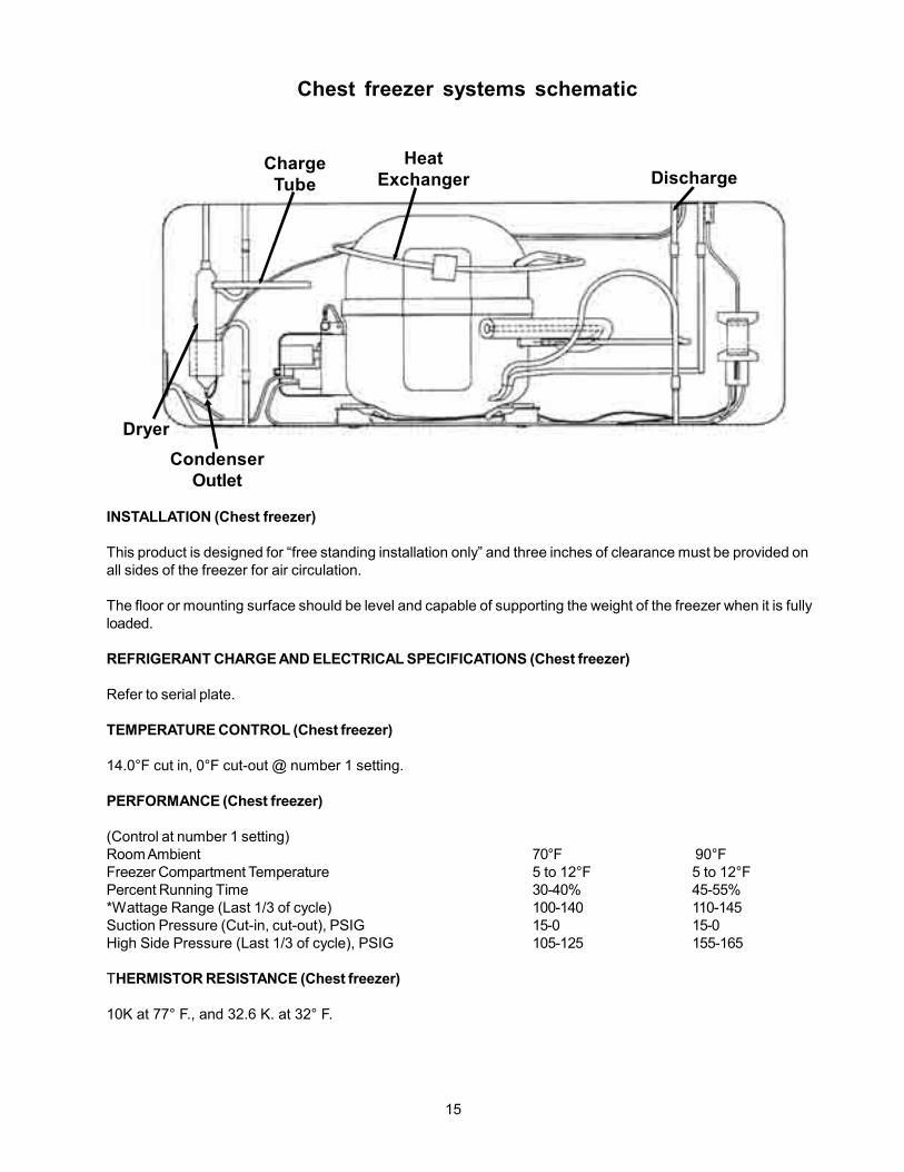
ChargeTube
HeatExchanger Discharge
Dryer
CondenserOutlet
INSTALLATION (Chest freezer)
This product is designed for “free standing installation only” and three inches of clearance must be provided onall sides of the freezer for air circulation.
The floor or mounting surface should be level and capable of supporting the weight of the freezer when it is fullyloaded.
REFRIGERANT CHARGE AND ELECTRICAL SPECIFICATIONS (Chest freezer)
Refer to serial plate.
TEMPERATURE CONTROL (Chest freezer)
14.0°F cut in, 0°F cut-out @ number 1 setting.
PERFORMANCE (Chest freezer)
(Control at number 1 setting)Room Ambient 70°F 90°FFreezer Compartment Temperature 5 to 12°F 5 to 12°FPercent Running Time 30-40% 45-55%*Wattage Range (Last 1/3 of cycle) 100-140 110-145Suction Pressure (Cut-in, cut-out), PSIG 15-0 15-0High Side Pressure (Last 1/3 of cycle), PSIG 105-125 155-165
THERMISTOR RESISTANCE (Chest freezer)
10K at 77° F., and 32.6 K. at 32° F.
Chest freezer systems schematic

16
Overload
Relay
C
B
N
L
RunCapacitor
CompressorController
C
B
Upright Freezer with Deluxe Electronic Control
Sample Wiring Diagramalways refer to diagram with product
A..BlackB..WhiteC..PurpleD..BlueE..GrayF..RedG..YellowH..BrownJ..Orange
IMPORTANTIF ANY GREEN GROUNDING WIRES ARE REMOVEDDURING SERVICING, THEY MUST BE RETURNED TOTHEIR ORIGINAL POSITION AND PROPERLY SECURED.
A
A
G
B
C
A
A
CB
B
B
POWER
WATER VALVE
NL
ICE MAKER
SEE DIAGRAM
COMPRESSOR
INTERIOR LIGHT
DEFROSTHEATER
B
DEFROSTTHERMOSTAT
J
AA
F
FA/BA A
JF
DOORSWITCH
THERMISTOR
ELECTRONICMODULE
9 VOLTBATTERY
H J G
G
D
DF
USERINTERFACE
FAN

17
D
D
D
F
E
C
C
AB
L N
ELECTRONIC CONTROL
SEEDIAGRAM
COMPRESSOR
FAN
DEFROSTTHERMOSTAT
DEFROSTHEATER
DOORSWITCH
INTERIORLIGHT
POWER ON
ALARMSENSOR
ALARMOFF ON
BUZZER
TEMP WARNING
Upright Freezer with Standard Electronic Control
Sample Wiring Diagramalways refer to diagram with product
Overload
Relay
C
B
N
L
RunCapacitor
CompressorController
C
B
A..BlackB..WhiteC..YellowD..RedE..OrangeF..Brown
IMPORTANTIF ANY GREEN GROUNDING WIRES ARE REMOVED DURING SERVICING, THEY MUST BE RETURNED TOTHEIR ORIGINAL POSITION AND PROPERLY SECURED.

18
SPECIFICATIONS (Upright Freezers)
REFRIGERANT CHARGE AND ELECTRICAL
Refer to serial plate.
DEFROST CONTROL
An automatic 30 minute defrosting period is initiated after every 12 hours of compressor running time. During thedefrosting period a thermostat will switch the defrost heater off after the frost on the evaporator has melted. Thedefrost thermostat closes at 10ºF and opens at 50ºF.
Upright Freezers with Deluxe Electronic Control
TEMPERATURE CONTROL
4.0°F cut in, -10°F cut-out @ number 1 setting.
PERFORMANCE
(Control at number 1 setting)Room Ambient 70°F 90°FFreezer Compartment Temperature 2 to 8°F 2 to 8°FPercent Running Time 35 - 45% 50 - 65%*Wattage Range (Last 1/3 of cycle) 115 - 140 120 - 145Suction Pressure (Cut-in, cut-out), PSIG 14 - 0 14 - 0High Side Pressure (Last 1/3 of cycle), PSIG 100 - 115 140 -155
Upright Freezers with Standard Electronic Control
TEMPERATURE CONTROL
4.0°F cut in, -10°F cut-out @ number 1 setting.
PERFORMANCE
(Control at number 1 setting)Room Ambient 70°F 90°FFreezer Compartment Temperature 2 to 12°F 2 to 12°FPercent Running Time 30 - 45% 45 - 65%*Wattage Range (Last 1/3 of cycle) 100 - 140 110 - 145Suction Pressure (Cut-in, cut-out), PSIG 14 - 0 14 - 0High Side Pressure (Last 1/3 of cycle), PSIG 100 - 125 140 -165
THERMISTOR RESISTANCE (Upright freezers Deluxe Electronic Control)
10K at 77° F., and 32.6 K. at 32° F.

19
SYSTEM SCHEMATIC
CondenserEvaporator Coil
SuctionTube
Compressor
Drier
High SideProcess
Tube
Capillary
Low Sid Process Tubee
Discharge
UPRIGHT FREEZER
Hot wall
20
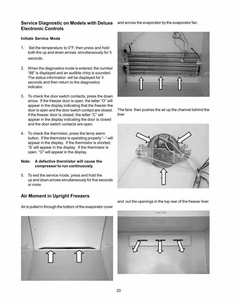
Service Diagnostic on Models with DeluxeElectronic Controls
Initiate Service Mode
1. Set the temperature to 0°F, then press and holdboth the up and down arrows simultaneously for 5
seconds.
2. When the diagnostics mode is entered, the number“88” is displayed and an audible chirp is sounded.The status information will be displayed for 3seconds and then return to the diagnosticsindicator.
3. To check the door switch contacts, press the downarrow. If the freezer door is open, the letter ”O” willappear in the display indicating that the freezer thedoor is open and the door switch contact are closed.If the freezer door is closed, the letter “C” willappear in the display indicating the door is closedand the door switch contacts are open.
4. To check the thermistor, press the temp alarmbutton. If the thermistor is operating properly “--” willappear in the display. If the thermistor is shorted,“S’ will appear in the display. If the thermistor isopen, “O” will appear in the display.
Note: A defective thermistor will cause thecompressor to run continuously.
5. To exit the service mode, press and hold theup and down arrows simultaneously for five secondsor more.
Air Moment in Upright Freezers
Air is pulled in through the bottom of the evaporator cover
and across the evaporator by the evaporator fan.
The fans then pushes the air up the channel behind theliner
and out the openings in the top rear of the freezer liner.

21
Energy Saving Ideas
• The freezer should be located in the coolest area ofthe room, away from heat producing appliances orheating ducts, and out of direct sunlight.
• Let hot foods cool to room temperature beforeplacing in the freezer. Overloading the freezer forcesthe compressor to run longer. Foods that freeze tooslowly may lose quality or spoil.
• Be sure to wrap foods properly and wipe containersdry before placing them in the freezer. This cuts downon frost build-up inside the freezer.
• Freezer shelves and baskets should not be lined withaluminum foil, wax paper, or paper toweling. Linersinterfere with cold air circulation, making the freezerless efficient.
• Organize and label food to reduce door/lid openingsand extended searches. Remove as many items asneeded at one time, and close door/lid as soon aspossible.
Important Safety Instructions
Read all instructions before using this freezer.
For your safety
Do not store or use gasoline or other flammable vaporsand liquids in the vicinity of this unit or any other appli-ance. Read product labels for flammability and otherwarnings.
Child Safety
• Destroy carton, plastic bags, and any exteriorwrapping material immediately after the freezer isunpacked. Children should never use these items forplay. Cartons covered with rugs, bedspreads, plasticsheets or stretch wrap may become airtightchambers and can quickly cause suffocation.
SECTION A - OWNERS GUIDE
Product Registration
The information contained in this Use and Care Guidewill instruct you on how to properly operate and care foryour product. Please read through the information con-tained in your literature pack to learn more about yournew freezer.
Record your Model and Serial Numbers
Record the model number and serial number of thisfreezer in the space provided below.
Model No.Serial No.
Register Your Product
The self-addressed PRODUCT REGISTRATION CARD(shown above) should be filled in completely, signed andreturned to Electrolux Home Products.
This Use and Care Guide provides operating instructionsfor your model. Use your freezer only as instructed inthis Use and Care Guide.

22
• A child might suffocate if he crawls into the freezer tohide or play. Remove the door/lid of the freezer whennot in use, even if you plan to discard the freezer.Many communities have laws requiring you to takethis safety precaution.
• Remove or discard any spacers used to secure theshelves during shipping. Small objects are a chokehazard to children.
Risk of Child Entrapment
Child entrapment and suffocation are not problems ofthe past. Junked or abandoned refrigerators or freezersare still dangerous – even if they will sit for “just a fewdays”. If you are getting rid of your old refrigerator orfreezer, please follow the instructions below to help pre-vent accidents:
• Remove the door/lid.
• Leave shelves in place so children may not easilyclimb inside.
• Have the refrigerant removed by a qualifiedtechnician.
Electrical InformationThese guidelines must be followed to ensure that safetymechanisms in the design of this freezer will operateproperly.
• Refer to the serial plate for correct electrical rating.The power cord of the freezer is equipped with athree-prong grounding plug for protection againstshock hazards. It must be plugged directly into itsown properly grounded three-prong receptacle,protected with a 15 amp time delay fuse or circuitbreaker. The receptacle must be installed inaccordance with the local codes and ordinances.Consult a qualified electrician. Receptacles withGround Fault Circuit Interrupters (GFCI) are NOTRECOMMENDED. DO NOT USE AN EXTENSIONCORD OR AN ADAPTER PLUG.
• If the voltage varies by 10 percent or more, freezerperformance may be affected. Operating the freezerwith insufficient power can damage the motor. Suchdamage is not covered under the warranty. If yoususpect your voltage is high or low, consult yourpower company for testing.
• To prevent the freezer from being turned offaccidentally, do not plug the unit into an outletcontrolled by a wall switch or pull cord.
• Do not pinch, knot, or bend the power cord in anymanner.
Other Precautions
• To defrost, always unplug unit first.
• Never unplug the freezer bypulling on the power cord.Always grip the plug firmly and pull straight out fromthe receptacle.
• Turning the control to “OFF” turns off the compressorbut does not disconnect power to other electricalcomponents.
First StepsBefore starting the freezer, follow these important firststeps.
Installation / Freezer Placement• Choose a place that is near a grounded electrical
outlet.
• The freezer should be located where surroundingtemperature will not exceed 110ºF (43ºC).Temperatures of 32ºF (0ºC) and below will NOTaffect freezer operation. Additional compressorheaters are not recommended.
• Allow space around the unit for good air circulation.Leave a 3 inch (75mm) space on all sides of thefreezer for adequate circulation.

23
LevelingThe freezer must have all bottom corners resting firmlyon a solid floor. The floor must be strong enough to sup-port a fully loaded freezer. It is VERY IMPORTANT foryour freezer to be level in order to function properly. If thefreezer is not leveled during installation, the door/lid maybe misaligned and not close or seal properly, causingcooling, frost or moisture problems.
To level Upright Units:After discarding crating screws and wood base, use acarpenter’s level to level the freezer from front to back.Adjust the plastic leveling feet in front, ½ bubble higher,so that the door closes easily when left halfway open.
To level Chest Units:If needed, add metal or wood shims between feet padsand floor.
Door Removal (Upright Models)• Unplug the unit.
• Gently lay freezer on its back, on a rug or blanket.
• Remove two base screws and base panel. Removewire from clips on bottom of cabinet, if required.
• Unplug connector, if required, by holding the cabinetconnector in place and pulling the door connectorout.
• Remove the bottom hinge screws.
• Remove the plastic top hinge cover.
• Remove the screws from the top hinge.
• Remove the top hinge from the cabinet.
• Remove the door and bottom hinge from the cabinet.
• To replace door, reverse the above procedures andsecurely tighten all screws to prevent hinge slippage.
BasePanel Base Panel Screws
Hinge Screws
Wire
Door Connector
Clips
Cabinet Connector
PLASTIC LEVELING FEET
CREATINGSCREW
Unpacking and Leveling- Upright Freezers
DISCARD THE (4)CRATINGSCREWS
AND (2) WOODBASES

24
Standard Electronic Temperature ControlFigure 2
Deluxe Electronic Temperature Control (SomeUpright Frost Free Models)Refer to the Electronics Control Guide supplied whenyou purchase a deluxe electronic upright model. SeeFigure 3 for deluxe electronics control panel.
Deluxe Electronic Temperature ControlFigure 3
Freezer Optional FeaturesYour freezer may have some or all of the featureslisted below. Become familiar with these features andtheir use and care.
Power On LightThe power on light indicates that the freezer is properlyconnected to an electrical power. The light glows evenwhen the temperature control is turned to “OFF”. If thelight goes out, refer to “Freezer does not run” in theAvoid Service Checklist section.
Electromechanical Temperature Alarm (AudibleOnly or Audible with Warning Light)This feature is designed to provide a warning of apossible malfunction. If the temperature of the foodrises to a level unsafe for long-term storage, thebuzzer will sound. The red light, if equipped, will alsoglow. The TempAlarm feature operates on householdelectricity. If power fails, the alarm will not function. AnON/OFF switch allows you to deactivate the TempAlarm when not wanted. The freezer is shipped withthe Temp Alarm in the “OFF” position (if equipped).After the freezer has run approximately four (4) hours,the red light, if equipped, will go off. Then you mayactivate the Temp Alarm without the alarm sounding.
Press the “ON” switch to activate the Temp Alarmfeature. To deactivate, press the “OFF” switch.
Lid Removal (Chest Models)• See lid removal instructions on the back of the
cabinet.
Setting the Temperature Control
Cool Down Period• For safe food storage, allow four (4) hours for freezer
to cool down completely. The freezer will runcontinuously for the first several hours. Foods thatare already frozen may be placed in the freezer afterthe first few hours of operation. Unfrozen foodsshould NOT be loaded into the freezer until freezerhas operated for four (4) hours.
• When loading freezer, freeze only three (3) pounds offresh food per cubic foot of freezer space at one time.Distribute packages to be frozen evenly throughoutthe freezer. It is not necessary to turn the controlknob to a colder setting while freezing food.
Electromechanical Temperature Control (Chest andSome Upright Models)
The electromechanical temperature control is locatedinside the freezer on upright models, and on the left ex-terior wall on chest models (see figure 1). The tempera-ture is factory preset to provide satisfactory food storagetemperatures. However, the temperature control is ad-justable to provide a range of temperatures for yourpersonal satisfaction. To adjust the temperature setting,turn the temperature control knob clockwise or counterclockwise. Allow several hours for the temperature tostabilize between adjustments.
Electromechanical ControlFigure 1
Standard Electronic Temperature Control (SomeUpright Frost Free Models)The standard electronic temperature control is locatedinside the freezer on upright models (see Figure 2).Temperature is factory preset to provide satisfactoryfood storage temperatures. To adjust the temperaturesetting, move the UP ( ) button for warmer tempera-ture and DOWN ( ) button for colder temperature onthe control panel. Allow several hours for the tempera-ture to stabilize between adjustments.

25
If the alarm sounds, be sure freezer is properly leveled,and the door/lid closes freely and seals properly. If yoususpect a technical malfunction, call an authorizedservice personnel immediately.
Electronic Temperature Alarm (Some ElectronicChest Models)This feature is designed to provide a warning if theinside temperature reaches an unsafe level. The TempAlarm feature operates on household electricity. It willnot function if household electricity is interrupted.
When the freezer is initially plugged in, the red TempAlarm indicator light blinks. The indicator light willcontinue to blink until the freezer has reached a safefreezing temperature. If a malfunction causes anunsafe temperature inside the freezer, the red light willblink and the buzzer will sound. To silence the buzzer,press the ALARM OFF button. The indicator light willcontinue to blink until a safe freezing temperature isagain reached. If the problem is not solved withintwelve (12) hours, the buzzer will turn on again. If theALARM OFF button is not pressed, the buzzer willturn itself off automatically after 48 hours, but the redTemp Alarm light will continue to blink.
Electronic Temperature Alarm (Some ElectronicUpright Models)Refer to the Electronics Control Guide supplied whenyou purchase a deluxe electronic upright model.
Slide-Out Basket (Some Upright Models)The slide-out basket, located at the bottom of thefreezer provides separate storage space for items thatare difficult to store on freezer shelves. To remove thebasket, pull out and lift up.
Security Lock with Pop-out KeyThis security lock fastens the door/lid snugly, ensuringthat stored food is secure. To lock or unlock thefreezer, push the key into the lock and turn. The keypops out of the lock after it has been turned.
Interior LightThe light comes on automatically when the door/lid isopened. To replace the light bulb, turn the temperaturecontrol to “OFF” and unplug the electrical cord.Replace the old bulb with a bulb of the same type andwattage.
Adjustable Shelf (Some Upright Models)This shelf can be moved to one of two positions. Liftthe shelf up and out to move to the desired position.
Slide-Aside Basket (Chest Models)This basket helps organize odd-shaped items. Toreach other packages in the freezer, slide the basketaside or lift out.
Fast Freezing Shelves (Manual Defrost UprightModels)These shelves contain cooling coils to freeze foodsquickly and allow cold air to constantly circulate through-out the freezer. Do not use sharp metal objects such asice picks or scrapers to clean the shelves. This coulddamage the shelves and reduce their cooling ability.These shelves are not adjustable.
Tilt-Out Shelf (Some Upright Models)This shelf is located inside on the freezer door and pro-vides additional storage space. To access an item, tiltthe top of the “basket” shelf down.
Tilt-Out Shelf

26
Drop Front (Some Upright Models)The drop front, located at the bottom of the freezer, pro-vides a separate compartment for small irregular shapeditems. Lift the front up and out to remove.
Basket Divider (Some Upright Models)Use these handy dividers to keep the various items storedin your baskets more organized. To change the locationof the divider simply slide your basket out, lift up oneach end of the divider until it is disengaged from thebasket, place divider in the desired location (make sureit is between two vertical wires) and press down firmlyon each end until it snaps into place.
Small Item Shelf (Some Upright Models)Use this shelf to store several of your single-servingmicrowavable dinners or other small items that you wantto keep in an easy-to-reach spot.
Pizza Shelf (Some Upright Models)Here is the place to store up to four extra-large boxes offrozen pizza without ever having to dig them out frombeneath a pile of other stored goods. To change the lo-cation of the pizza shelf: support the bottom center ofthe shelf with one hand and use your other hand to gen-tly ease each support tab outward until they have alldropped between the edge of the shelf and the liner wall.It may help to slide the supporting shelf slightly to theside opposite that in which you are removing the tabs in
order to get a larger gap between the edge of the sup-porting shelf and the liner wall.
Next, locate the pizza shelf beneath the shelf nearestyour desired location and snap each tab upwards be-tween the wire or glass shelf and liner until the tab hassnapped into place and is resting on top of the support-ing shelf. Repeat for each tab until all four are firmly inplace and then load with desired items.
Chest Divider (Some Chest Models)Use these clever dividers to custom-arrange a variety ofdifferent sized storage bins in the bottom of your chestfreezer. Use the peel-n-stick labels found in your litera-ture packet to help remind you which items are storedwhere. If you have an item that isn’t already covered byone of the pre-printed labels then use one of the blanklabels and a permanent marking pen to make your owncustom label. Labels can be peeled off when no longerneeded and replaced by new and different ones.

27
Examples of Chest Divider Configurations:
Compressor Mounted Drain Pan (Most Upright FrostFree Models)Most upright frost free freezers are equipped with a com-pressor mounted drain pan that collects condensate dur-ing each defrost cycle. This compressor mounted drainpan takes advantage of the heat generated by the com-pressor to evaporate condensate water so there is noneed to empty the pan during each defrost cycle.
Care and Cleaning• Damp objects stick to cold metal surfaces. DO NOT
touch interior metal surfaces with wet or damp hands.• The freezer must be unplugged (to avoid electrical
hazard) from power source when defrosting the unit.
Some upright and chest freezers are frost free and
defrost automatically, but should be cleaned occasion-ally.
Between DefrostingsTo avoid frequent defrosting, occasionally use a plasticscraper to remove frost. Scrape with pulling motion.NEVER use a metal instrument to remove frost.
DefrostingIt is important to defrost and clean the freezer when ¼ to½ inch of frost has accumulated. Frost may tend to ac-cumulate faster on the upper part of the freezer due towarm, moist air entering the freezer when the door/lid isopened. Remove food and leave the door/lid open whendefrosting the freezer.
To Defrost Upright Models with Defrost Drain:• Remove the drain plug on the inside floor of the freezer
by pulling it straight out.
• To access external drain tube on models with a basepanel, first remove the two screws from the basepanel. Locate the drain tube near the left centerunder the freezer.
• Place a shallow pan under the drain tube. Defrostwater will drain out. Check the pan occasionally sowater does not overflow (see figure 1).
• A ½ inch garden hose adapter can be used to drainthe freezer directly into a floor drain. If your model isnot equipped with an adapter, one can be purchasedat most hardware stores.
• Replace the drain plug when defrosting and cleaningare completed. If the drain is left open, warm air mayenter the freezer.
To Defrost Chest Models with Defrost Drain:• Place a shallow pan or the Divider/Drain Pan (ifequipped) beneath the drain outlet. Pull out the outside

28
drain plug (see figure 2).
A ½ inch garden hose adapter can be used to drain thefreezer directly into a floor drain (see figure 3).
If your model is not equipped with an adapter, one canbe purchased at most hardware stores.
• Pull out the drain plug inside the freezer (see figure 4).
Defrost water will drain out. Check pan occasionallyso water does not overflow.
• Replace the drain plugs when defrosting andcleaning are completed. If the drain is left open, warmair may enter the freezer.
To Defrost Models without Defrost Drain:• Place towels or newspapers on the freezer bottom to
catch the frost. The frost will loosen and fall.
• Remove the towels and/or newspapers.
• If the frost is soft, remove it by using a plastic scraper.If the frost is glazed and hard, fill deep pans with hotwater and place them on the freezer bottom.
• Close the freezer door/lid. Frost should soften in aboutfifteen (15) minutes.
• Repeat this procedure is necessary.
Cleaning The InsideAfter defrosting, wash inside surfaces of the freezer witha solution of two (2) tablespoons of baking soda in one(1) quart (1.136 liters) warm water. Rinse and dry. Wringexcess water out of the sponge or cloth when cleaningin the area of the controls, or any electrical parts.
Wash the removable parts with the baking soda solutionmentioned above, or mild detergent and warm water. Rinseand dry. NEVER use metallic scouring pads, brushes,abrasive cleaners or alkaline solutions on any surface.DO NOT wash removable parts in a dishwasher.
Cleaning The OutsideWash the cabinet with warm water and mild liquid deter-gent. Rinse well and wipe dry with a clean soft cloth.Replace parts and food.
Do not use razor blades or other sharp instruments, whichcan scratch the freezer surface when removing adhesivelabels.Any glue left from the tape can be removed with amixture of warm water and mild detergent, or touch theresidue with the sticky side of the tape already removed.DO NOT REMOVE THE SERIAL PLATE.
Power Failure / Freezer FailureRisk of Child Entrapment
If leaving the freezer door/lid open while on vacation, makecertain that children cannot get into the freezer and be-come entrapped. DO NOT open freezer door/lid unnec-essarily if freezer is off for several hours.

29
Vacation and Moving Tips
Short Vacations:• Leave the freezer operating during periods of non-
use of less than three (3) weeks.
Long Vacations:If the freezer will not be used for several months:
• Remove all food and unplug the power cord.
• Clean and dry the interior thoroughly.
• Leave the freezer door/lid open slightly, blocking itopen if necessary, to prevent odor and mold growth.
Moving:When moving the freezer, follow these guidelines to pre-vent damage:
• Disconnect the power cord plug from the wall outlet.
• Remove foods, then defrost, and clean the freezer.
• Secure all loose items such as base panel, baskets,and shelves by taping them securely in place toprevent damage.
• In the moving vehicle, secure freezer in an uprightposition to prevent movement. Also, protect outsideof freezer with a blanket or similar item.
IF APOWER FAILURE OCCURS:Frozen foods will stay frozen for at least 24 hours if thefreezer is kept closed. If the power failure continues,pack seven or eight pounds of dry ice into the freezerevery 24 hours. Look in the Yellow Pages under “DryIce”, “Dairies”, or “Ice Cream Manufacturers” for local dryice suppliers. Always wear gloves and use caution whenhandling dry ice.
If the freezer has stopped operating, see the “Freezerdoes not run” section in theAvoid Service Checklist sec-tion of this use and care guide. If you cannot solve theproblem, call an authorized service personnel immedi-ately.
If the freezer remains off for several hours, follow thedirections above for the use of dry ice during a powerfailure. If necessary, take the food to a local locker plantuntil the freezer is ready to operate. Look in the YellowPages under “Frozen Food Locker Plants”.

30

31

32

33
SECTION B - ELECTRONIC CONTROLSGUIDE
TEMPERATURE CONTROL
TEMPERATURE SETTING
The desired temperature inside the freezer can be setusing the UP (%) and DOWN (%) buttons on thecontrol panel, located on the door/lid of the freezer.Press either the UP or DOWN buttons once to displaythe current setting. You may now use the UP andDOWN buttons to change the temperature setting toone which suits your needs. The range of settings is -10ºF to 10ºF (-24ºC to -12ºC) (see figures 1 and 2).The display will return to showing the temperature ofthe cabinet after five (5) seconds of inactivity.
You may also turn off the freezer by pressing the UPbutton when at temperature setting of 10ºF (-12ºC). Thedisplay will read 0FF (see figure 3). The freezer will notcool anything while it is in 0FF position. The door lightwill continue to operate while in 0FF .
WARNING: The freezer still has electrical powerwhile in 0FF. Disconnect freezer from the outletbefore cleaning or moving it.
TEMPERATURE MODE CHANGE
Temperature display can be changed from ºF to ºC to ºFby pressing the ALARM RESET and DOWN arrow si-multaneously until the control panel beeps. The displaywill change to the other mode.
EXTREMEFREEZE
Extreme Freeze enables the compressor to run continu-ously to help cool large quantities of warm (room tem-perature) foods faster. Always cool sown hot foods toroom temperature before placing them in the freezer. Usethis feature just prior to adding large quantities of unfro-zen foods (not to exceed three (3) pounds per cubic footof freezer space). For example, do not place more than45 pounds of room temperature food into a 15 cubic footfreezer.To activate the Extreme Freeze feature, push the Ex-treme Freeze button. The control panel will beep onceand the display will now read “FF” indicating that Ex-treme Freeze has begun (see figure 4).
For your convenience, Extreme Freeze will automati-cally turn off after a period of 72 hours and the freezerwill return to the previous temperature setting. You maydeactivate Extreme Freeze at anytime by pressing theExtreme Freeze button. The display will return to show-ing the current temperature inside the freezer and thecontrol panel will beep once.
DISPLAY LOCKOUT
Press and hold the ALARM RESET key until the controlpanel beeps to activate or deactivate the Display Lock-out feature which prevents the user from accidentallychanging the temperature and extreme freeze settings.“L0C ” (LOCK) will be displayed for three (3) secondsindicating that the control panel is locked (see figure 5).Once in lockout when a key is pressed, “L0C ” will dis-play for three (3) seconds. When the lockout is deacti-vated, “UL” (UNLOCK) will display for 1 second (see fig-ure 6).
34
ALARM FUNCTIONS
TEMPERATUREALARM
If the cabinet temperature rises to a level above 23ºF(-5ºC), a high temperature alarm will be activated. Thecontrol panel will beep every five (5) seconds, the redalarm light will glow and the display will flash. This willcontinue until the problem is determined, corrected andtemperature once again drops to a level below 23ºF(-5ºC). You may stop the beep by pressing the ALARMRESET button. To also stop the display from flashing,press and hold theALARM RESET button until the con-trol panel beeps. TemperatureAlarm will reactivate itselfupon reaching a safe temperature.
DOOR / LID AJAR ALARM
The door/lid alarm will activate if it is ajar for more thanfive (5) minutes. The control panel will beep every five (5)seconds, the red alarm light will glow and the displaywill alternate between “d” (DOOR/LID) and the cabinettemperature (see figure 7). Press the ALARM RESETbutton to turn the audible alarm (beep) off. The displaywill keep flashing and the red light will stay on. Close thedoor/lid of the freezer to return it to normal operation.
POWER FAILURE (Models with 9 Volt Battery)
If power to the freezer is lost, the power loss alarm willactivate. The display will be off but the control panel willbeep every minute (see figure 8). To turn the audiblealarm (beep) off, press the ALARM RESET button. Theaudible alarm will also turn off automatically when poweris reconnected to the freezer. The temperature alarmwill activate if the temperature of the cabinet rises to alevel above 23ºF (-5ºC) during power failure. The red alarmlight however, will not illuminate.
SYSTEM ERROR ALARM
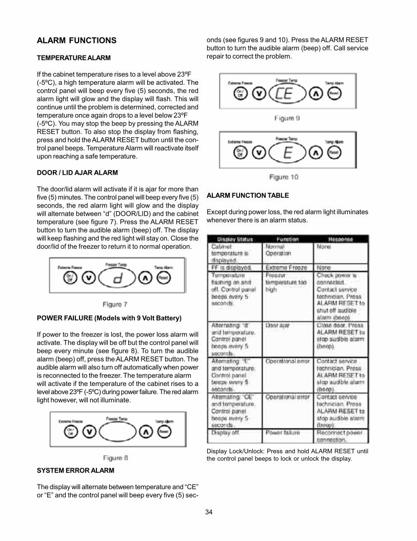
The display will alternate between temperature and “CE”or “E” and the control panel will beep every five (5) sec-
onds (see figures 9 and 10). Press the ALARM RESETbutton to turn the audible alarm (beep) off. Call servicerepair to correct the problem.
ALARM FUNCTION TABLE
Except during power loss, the red alarm light illuminateswhenever there is an alarm status.
Display Lock/Unlock: Press and hold ALARM RESET untilthe control panel beeps to lock or unlock the display.

35
SECTION C - ELECTRICAL OPERA-TION
Electrical mechanical control models:
Electrical mechanical control models have three basiccircuits:
1. The electrical circuitry that controls and powers thecompressor.
2. The electrical circuitry for the alarm function, andpower on indicator light.
3. The electrical circuitry for the freezer light.
Compressor circuit
When powers applied to the freezer. Line is connectedto the electronic module and the lid switch. Neutral isconnected to one side of the compressor, interior light,and the electronic module. With line and neutral bothapplied to the electronic module, the module activatesand checks the resistance of the cold control. The re-sistance of the cold control tells electronic module, ifthe control is turned off or at what temperature the freezershould operate. The temperature in the freezer is sensedby a thermistor, which is a device that changes resis-tance as the temperature changes. If the cold control isset at any position other than off, the electronic modulereads the resistance of the thermistor, and calculatesthe temperature in the freezer compartment. If the tem-
perature in the freezer is above the upper limits of thecontrol setting, the electronic module applies line volt-age to the compressor circuit, starting the compressor.With the compressor operating the sealed system coolsthe freezer compartment. As the freezer compartmentcools the resistance of the thermistor increases. Theelectronic module monitors the resistance of the ther-mistor as it increases. When the temperature in thefreezer reaches the lower limits of the control setting theresistance of the thermistor tells electronic module toremove power from the compressor.
Alarm function circuit
The components that make up the alarm function andpower on light circuits are the user interface and elec-tronic module. The alarm function is designed to alertthe user if the temperature in the freezer goes above23°F for any reason. The power on light gives the user avisual indication that power is applied to the freezer. Noteboth the power on light and the alarm function operatewith the cold control set to off or at a temperature set-ting.
The user interface is made up of the alarm off switch andtwo indicator lights. A yellow light to indicate that poweris being applied to the freezer and a red light for thetemperature alert.
When power is applied to the freezer, the electronic mod-ule applies power to the yellow indicator light causing itto glow.
The electronic module constantly monitors the tempera-ture in the freezer compartment. If the temperature inthe freezer compartment goes above 23°F, the electronicmodule will beep every five seconds and the red alarmlight will flash. The beeping will continue until either thefreezer goes below 23°F or the alarm off switch is pushed.The red indicator light will continue to flash until the tem-perature in the freezer goes below 23°F.
Freezer light circuit
The freezer light circuit is made up of the lid switch andthe freezer interior light. When the freezer lid is open tocontacts of the lid switch close and apply power to thefreezer interior light.

36
Standard electronic control models:
The models with the standard electronic control havefive basic electrical circuits:
1. The sealed system circuit made up of the electroniccontrol, compressor and evaporator fan motor.
2. The defrost circuit is made up of the electroniccontrol, defrost thermostat and the defrost heater.
3. The interior light circuit is made up of the door switchand the interior light.
4. The power on light circuit is made up of the poweron light.
5. The alarm circuit is made up of the alarm sensor,temperature warning light, alarm off/on switch andthe buzzer.
Sealed system circuit
When the freezer is plug-in, powers apply to electroniccontrol. The electronic control has a keypad with upand down arrows that allows the user to turn the controloff, or select the freezers operating temperature. Thepreset temperature settings are shown in the control’sdisplay as numbers from zero to seven, with zero beingoff and seven being the coldest.
A thermistor in the control is used to sense the tempera-ture of the freezer. If the electronic control is program forany number, other than zero, the control reads the resis-tance of the thermistor and compares it to the pre-pro-grammed temperature setting. If the resistance indi-cates that the temperature in the freezer is above theupper limits of the preprogramed temperature setting,the control applies power to the compressor and theevaporator fan motor. This cools the freezer compart-ment and causes the resistance of the thermistor to in-crease. When the temperature in the freezer compart-ment reaches the lower limits of the control setting, thecontrol removes power from the compressor and evapo-rator fan motor. By cycling the compressor and evapo-rator fan motor off and on electronic control maintainsthe preset temperature in the freezer compartment.
Defrost circuit
The electronic control has a preprogram defrost programthat performs a 30 minute defrost cycle after every 12hours of compressor run time. After 12 hours of com-pressor run time, the defrost section of the electroniccontrol activates providing line to neutral voltage acrossthe defrost thermostat and the defrost heater for 30 min-utes. The defrost thermostat is a safety device that isused to prevent damage to the cabinet by the defrostheater. Although the control provides line to neutral volt-age for 30 minutes, during a normal defrost cycle, thecontacts of the defrost thermostat open at about the 12to 14 minute mark removing power from the defrostheater. The remaining time of the defrost cycle allowsthe water to drip off the evaporator, so it does not re-freeze when the compressor starts at the end of thedefrost cycle.
Interior light circuit
Whenever powers is applied to the freezer, line to neu-tral voltage is applied across the door switch and interiorlight circuit. When the freezer doors is close the con-tacts of the door switch are open preventing current fromflowing in the circuit. When the door is opened the con-tacts of the door switch close allowing current to flowthrough the circuit causing the interior light to glow.

37
Power on indicator light circuit
The power on indicator light is connected between lineand neutral. Whenever power is applied to the freezerthe indicator light glows, giving a visual indication thatpowers is applied to the freezer.
Alarm circuit
The alarm circuit is a series parallel circuit, with linevoltage being applied to the alarm sensor. If the tem-perature in the freezer goes above 23°F. the contacts ofalarm sensor close. This applying power to the parallelcircuit formed by the temperature warning light circuitand the alarm off/on switch and the buzzer circuit. Thebuzzer may be deactivated by placing the alarm off onswitch to the off position.

38
Deluxe electronic control models:
The models with the deluxe electronic control have fivebasic electrical circuits:
1. Electronic module and user interface circuit that ismade up of the user interface, electronic moduleand thermistor.
2. Sealed system circuit that is made up of electronicmodule, the evaporator fan motor and thecompressor.
3. Defrost circuit that is made up of electronic module,defrost heater, and defrost thermostat.
4. Interior light circuit that is made up of the electronicmodule, door switch and the interior light.
Note: The 9 V battery backup is not available onsome models and the icemaker comes asa kit.
Electronics module and user interface circuit
The electronic module controls the operation of the freezerwith inputs from the arrows on the interface, the extremefreeze switch, the alarm off switch, the thermistor, and doorswitch. The outputs of the electronic module are to thedisplay of the interface, the compressor and evaporator fancircuit, the defrost circuit and the temp alarm indicator light.
The electronic module uses the input from the up and downarrows to raise or lower the temperature at which the freezeroperates or to turn the control off. The input from the ex-treme freeze switch tells the control to apply power to thecompressor evaporator fan circuit for 72 hours or until theswitch is pushed again. During an extreme freeze opera-tion, the 30 minute defrost occurs every 12 hours of com-pressor run time. Pushing the alarm off switch tells theelectronic module to turn the beeper off when the alarmfunction is operating. The input from the thermistor allowselectronic module to calculate the temperature in the freezercompartment. With this knowledge the module cycles thecompressor and evaporator fan circuit off and on to main-tain the temperature at the program level. The module alsouses this information to activate the alarm circuit, when theinput from the thermistor indicates the temperature in thefreezer compartment is about 23°F. When the door is openedthe closing of the contacts the door switch tells the timerfunction of the module to start a five minute countdown. Ifthe contacts of the door switch do not open within the fiveminute the module activates the door ajar alarm.
Sealed system circuit
The electronic module, evaporator fan motor, and compres-sor form a series circuit. When the electronic module deter-mines that the temperature in the freezer is above it’s pre-set limits, the relay on the module closes and provides lineto neutral voltage to the evaporator fan motor and the com-pressor. With the evaporator fan motor and compressorrunning the freezer compartment cools down. When thetemperature in the freezer compartment reaches the presetlower limit in the module the relay opens removing powerfrom the evaporator fan motor and the compressor.
Defrost circuit
The timer section of the electronic module, records the com-pressor run time. When the accumulated run time of thecompressor reaches 12 hour, the module turns off the com-pressor and activates defrost circuit. For 30 minutes themodule supplies lined a neutral voltage to the series circuitformed by the defrost heater and the defrost thermostat.The defrost thermostat is a safety device connected in thecircuit to protect the freezer liner, if the defrost heater is al-lowed to remain on too long. In a normal defrost cycle thecontacts of the defrost thermostat opens at about the 12 to14 minute mark stopping current flow in the circuit. Duringthe rest of the 30 minutes the water is allowed to drain offthe evaporator, so it does not refreeze when the compres-sor restarts.
A
A
G
B
C
A
A
CB
B
B
POWER
WATER VALVE
NL
ICE MAKER
SEE DIAGRAM
COMPRESSOR
INTERIOR LIGHT
DEFROSTHEATER
B
DEFROSTTHERMOSTAT
J
AA
F
FA/BA A
JF
DOORSWITCH
THERMISTOR
ELECTRONICMODULE
9 VOLTBATTERY
H J G
G
D
DF
USERINTERFACE
FAN

39
Interior light circuit
The interior light circuit is a series circuit formed by theelectronic module, the door switch and the interior light.The electronic module provides line to neutral voltage to theinterior light circuit, whenever powers applied to the freezer.When the freezer door is closed, the contacts of the of thedoor switch are open, preventing current flow in the circuit.When the door is open, the contacts of the switch are closedand current flows through the circuit causing the light toglow. When current flows in the circuit the timing section ofelectronic module is activated for a five minute countdown.If the current flow in the interior light circuit is interrupted, byclosing the door, which in turn opens the contacts of thedoor switch, the countdown is stopped. If the door is notclosed within the five minute, the door alarm function isactivated, notifying the user to close the door.

40
SECTION D - REFRIGERATION SYSTEM &SERVICE
NOTICE: Instructions given here are furnished as aguide. Persons attempting to use these to makerepairs to the sealed refrigeration system shouldhave a working knowledge of refrigeration andprevious training on sealed system repair.
Safety
Compressor Testing: Whenevertesting a compressor, extremecaution should be used to preventdamaging the terminals. Acompressor with a damagedterminal or a grounded terminalwinding can expel a terminal fromits insulated housing when thecompressor is energized. If thishappens, a mixture of refrigerantand oil will be released that couldbe ignited by an external heatsource (open flame, heater, etc.).Also, if there is air in the systemwhen it happens, a spark at thecompressor shell could ignite therefrigerant and oil mixture.
Charging Sealed Systems: Over
charging a freezer system withrefrigerant can be dangerous. If theovercharge is sufficient to immersethe major parts of the motor andcompressor in liquid refrigerant, asituation has been created which,when followed by a sequence ofcircumstances, can lead to thecompressor shell seam separating.
A hydraulic block occurs preventingthe compressor from starting. Thiscondition is know as locked rotor.Electrical current continues to flowthrough the compressor motorwindings which become, in effect,electrical resistance heaters. Theheat produced begins to vaporizethe excess refrigerant liquid,causing a rapid increase in systempressure. If the compressorprotective devices fail, the pressurewithin the system may rise toextremes far in excess of the designlimits. Under these conditions, theweld seam around the compressor
shell can separate with explosiveforce, spewing oil and refrigerantvapor which could ignite.
To eliminate this exceedingly rarebut potential hazard, never addrefrigerant to a sealed system. Ifrefrigerant is required, evacuate theexisting charge and recharge withthe correct measured amount ofrefrigerant specified for the system.
Soldering
CAUTION Wear the proper and approved safetyglasses when working with or on anypressurized system or equipment. Havean approved dry type fire extinguisherhandy when using any type of gasoperated torch.
1. All joints to be soldered must have a proper fit. Theclearance between tubes to be soldered should befrom .001” to .006”. It is not practical to actuallymeasure this, however you do not want a dry fit or aloose fit. The tubing joints should overlap about thedistance of their diameter except for restrictor tubeswhich should be inserted 1.25”
2. Clean all joint areas with fine steel wool or preferablyan abrasive cloth, such as grit cloth No. 23 or“Scotch-Brite.”
3. Apply a thin film of a liquid flux recommended forsilver soldering to the surfaces to be joined, and tothe surfaces immediately adjacent to the joint.
4. Align the tubing so that is no stress on the joint. Donot move the tubing while the solder is solidifying orleaks will result.
CAUTION During the application of heat, usewet cloths to prevent the heat fromconducting to areas other than thesoldered joint. Use a sheet of metal asa heat deflector to keep the flame awayfrom inflammable materials andpainted surfaces.
5. Use a torch of adequate capacity so that the jointcan be quickly heated with a minimum of heat travelto other points. Use a good grade of silver solder.
6. Solder the connections. If the tubing is properlycleaned and fluxed, solder will flow readily. Do notuse an excessive amount of solder, just enough tomake a good bond.

41
7. Allow the joint to cool then wash exterior withwater to remove flux.
Refrigeration System
Basic components of a refrigeration system are:
1. The compressor located in the machinecompartment.
2. The condenser that is foamed to the outer walls ofthe cabinet.
3. The evaporator mounted to the rear wall of the foodcompartment or
attached to the food compartment liner.
4. The capillary tube connects the output end of thedrier to the input of the evaporator.

42
5.The filter-drier located in the machine compartment.
6.The suction line connects the output of theevaporator to the input side of the compressor.
Note: Portions of the capillary tube and thesuction line are soldered together to formthe heat exchanger.
Refrigerant Cycle
The refrigerant cycle is a continuous cycle that occurswhenever the compressor is in operation. Liquid refrig-erant is evaporated in the evaporator by the heat thatenters the cabinet through the insulated walls and theheat introduced by the product load and door openings.The refrigerant vapor is then drawn from the evaporator,though the suction line, to the compressor. The pres-sure and temperature of the vapor is raised in the com-pressor by compression, and the vapor is then forcedthrough the discharge valve into the discharge line andinto the condenser. Air passing over the condenser sur-face removes heat from the high pressure vapor, whichthen condenses to a liquid. The liquid refrigerant flowsfrom the condenser to the evaporator, through the small
diameter liquid line (capillary tube). Before it enters theevaporator, it is sub-cooled in the heat exchanger by thelow temperature suction vapor in the suction line.
Low or High Side Leak or Undercharge
A loss of refrigerant results in excessive or continuouscompressor operation; above normal freezer compart-ment temperature; a partially frosted evaporator (depend-ing on the amount of refrigerant loss); above normalfreezer compartment temperature; low suction pressure(vacuum) and low wattage. The condenser will be “warmto cool,” again, depending on the amount of refrigerantlost.
When refrigerant is added, the frost pattern will improve;the suction and discharge pressures will rise; the con-denser will become hot; and the wattage will increase.In the case of a low side refrigerant leak, resulting in acomplete loss of refrigerant, the compressor will run, butwith no refrigeration. Suction pressure will drop belowatmospheric pressure, and air and moisture will be drawninto the system, saturating the filter-drier.
If a slight undercharge of refrigerant is indicated, and noleak could be found after a thorough leak test, the chargecan be corrected without changing the compressor.
If there is reason to believe the system has operated fora considerable length of time with no refrigerant, and theleak occurred in the evaporator, excessive amounts ofmoisture may have entered the system. In such casesthe compressor may need to be replaced to prevent re-petitive service.
If a high side leak is located and some refrigerant re-mains in the system, it is not necessary to change thecompressor.
Test for Refrigerant Leaks
If the system is diagnosed as short of refrigerant and thesystem has not been recently opened, there is probably
SYSTEM SCHEMATIC
Condenser Evaporator
Compressor
Discharge
Drier
Suction TubeCapillary
Condenser Bottom Loop

43
a leak in the system. Adding refrigerant without firstlocating and repairing the leak, or replacing the compo-nent would not permanently correct the difficulty. THELEAK MUST BE FOUND. Sufficient refrigerant mayhaveescaped to make it impossible to leak test effectively.In such cases, add a 1/4” line piercing valve to the com-pressor process tube. Add sufficient refrigerant to in-crease the pressure to 75 lb. per sq. inch. Through thisprocedure, slow leaks are more easily detected beforedischarging the system.
Note: The line piercing valve (clamp on type)should be used for adding refrigerant andtest purposes only. It must be removed fromthe system after it has served its purpose.
Procedure for Checking Condenser Leaks
Before checking for leaks in the condenser, check allaccessible system components and joints for leaks.
If a condenser leak is suspected:
1. Discharge the system by using refrigerant recoveryequipment.
2. Disconnect the condenser tube from the drier andpinch off and solder both the drier and condensertube closed.
3. Remove the discharge tube from the compressorand seal the opening to the compressor.
4. Connect a pressure gauge and access valve to thedischarge tube and pressurize to 250 lbs. using drynitrogen or carbon dioxide.
Never pressurize with oxygen.
Never open a high pressure tankunless it is equipped with apressure regulator. Never put highpressure on the dome of thecompressor. Make sure the gaugeand fitting is in good condition anddo not leak.
5. Leave the pressure on the condenser for 24 hours.Any drop in pressure is an indication of a leak.
Evacuating and Recharging
CAUTION: Check the serial plate for the correctrefrigerant type. It is extremely important toverify the type of refrigerant in the systembefore starting any sealed system repairs.
CAUTION: With the possible exception of thevacuum pump, all service equipmentthat comes in contact with R-134aduring evacuation and recharging mustbe dedicated. Accordingly, R-134a willrequire a dedicated charging cylinder,manifold gauge set, process tubeadaptors, and hoses. Any residualmineral oil on other tools (tubingcutter, etc.) must be thoroughly cleanedoff before using on R-134a/Ester oilsystems. It will be necessary to checkwith the manufacturer of your vacuumpump for refrigerant and oilcompatibility issues.
CAUTION: If you use a vacuum pump with mineraloil to evacuate an R-134a system, it isABSOLUTELY ESSENTIAL to have ashut-off valve between the pump andyour manifold gauge set. The hand valvemust be closed during all times whenthe vacuum pump is not operating. Thiswill prevent the migration of mineral oilvapor into the R134a/Ester oil system. Ifthe vacuum pump should stop duringevacuation for any reason, the handpump shut-off valve must be closedimmediately.
CAUTION: Insure that your refrigeration hoses arespecified for use with R-134arefrigerant. Research has shown thatcompounds in standard refrigerationhoses may enter sealed systems andultimately restrict the cap tube in anR-134a system.
Equipment Needed For Evacuation &Recharging:
• Heated charging cylinder.
• Standard 3-port manifold gauge set:4 charging hoses.Tee fitting with valve core stem removed.(Robinair No. 40396).Hand shut-off valve (Robinair No.40380).
• Two stage vacuum pump.
• Process tube adapter kit (Robinair No. 12458).
• Tubing cutter.
• Pinch-off tool capable of making leak proof seal.

44
• Complete brazing torch set.
• Small 3-corner file.
• Grit cloth or Scotch-Brite.
• 45% silver solder and flux.
Installing Evacuation and RechargingEquipment:
1. Disconnect the appliance from electrical supply.
2. If compressor was replaced, install correct sizedprocess tube adaptor on process tube. Ifcompressor was not replaced, cut process tube withtubing cutter leaving as much tube as possible andinstall correct size process tube adaptor.
3. Install correct sized process tube adaptor onhigh-side process tube.
4. Attach refrigeration service gauge manifold tosystem in following order:
• Low-side (compound gauge) hose to suction sideprocess tube adaptor.
• High-side (pressure gauge) hose to high-sideprocess tube adaptor.
• Center port manifold hose before hand shut-offvalve to charging cylinder.
• Center port manifold hose after hand shut-off valveto vacuum pump.
Evacuating System
WARNING: R-134A SYSTEMS AREPARTICULARLY SUSCEPTIBLE TOMOISTURE CONTAMINATION WHICHCAN ONLY BE PREVENTED BYEVACUATING THE SYSTEM FOR AMINIMUM OF 30 MINUTES TO ATTAIN AMINIMUM 29.9 INCH (500 MICRON ORLOWER) VACUUM.
To achieve the required levels of evacuation, a properlymaintained two stage vacuum pump in good condition isrequired. It is absolutely essential to maintain yourvacuum pump according to the manufacturer’sinstructions including required oil changes at therecommended intervals. Vacuum pump oil should alwaysbe changed after evacuating a contaminated system.Vacuum pump performance should be checkedperiodically with a micron gauge.
1. Make certain that charging cylinder valve, handshut-off valve, and manifold gauge valves are closed.
2. Start vacuum pump.
3. Open hand shut-off valve and slowly open bothmanifold valves, turning counterclockwise, for twofull rotations.
CAUTION: If high vacuum equipment is used, justcrack both manifold valves for a fewminutes and then open slowly for thetwo full turns counterclockwise. This willprevent the compressor oil fromfoaming and being drawn into thevacuum pump.
4. Operate the vacuum pump for a minimum of 30minutes to a minimum of 29.9” (500 micron) vacuum.
5. Close hand shut-off valve to vacuum pump. Watchcompound gauge for several minutes. If reading rises,there is a leak in the system, go to step 6. If no leakis indicated, stop vacuum pump. System is nowready for charging.
6. If a leak is indicated, stop vacuum pump andintroduce a small charge of refrigerant into systemby cracking valve on bottom of charging cylinderuntil system is pressurized to 40 or 50 lbs psig.
7. Leak test low-side. Close compound gauge.Run compressor for a few minutes and leak testhigh side.
When leak is found, recapture refrigerant using EPAapproved recovery system Repair and go backto step 1.
Charging the System
CAUTION: Check the serial plate for the correctrefrigerant type. It is extremelyimportant to verify the type ofrefrigerant in the system beforestarting any sealed system repairs.
CAUTION: After charging the system with liquid becertain to wait at least 5 minutes beforestarting the compressor to give therefrigerant a chance to dispersethroughout the system. Otherwise thecompressor could be damaged byattempting to pump excessivequantities of liquid.

45
Preparing The Charging Cylinder:
1. Make certain that hand shut-off valve to vacuumpump is closed.
2. Close high-side manifold gauge valve.
3. Set charging cylinder scale to pressure indicated oncylinder pressure gauge.
4. Observe refrigerant level in sight glass. Subtractamount to be charged into system and note shut offpoint.
5. Open charging cylinder valve slowly and allow propercharge to enter system.
6. As soon as refrigerant in sight glass has gone downto predetermined level, close charging cylinder valve.
WARNING: DISCONNECT THE CHARGINGCYLINDER HEATER AT THIS TIME TOPREVENT THE CYLINDER PRESSUREFROM EXCEEDING ITS MAXIMUMLIMITS.
7. Allow system to sit for five minutes.
8. Turn on compressor and allow it to run for a fewminutes and monitor system pressures.
9. When satisfied that the unit is operating correctly,clamp the high-side process tube with the pinch-offtool while the unit is still running.
10. Slowly open the high-side manifold gauge valve toallow the compressor to remove any refrigeranttrapped in the high-side hose and the processfitting.
11. Close both of the manifold gauge valves. If thehigh-side gauge reading rises, the pinch-off must becorrected before proceeding.
12. Remove the high-side process tube adaptor andsolder the process tube closed.
13.Clamp the low-side process tube with the pinch-offtool while the unit is running. Remove the low-sideprocess tube adaptor and solder the process tubeclosed.
14. Check the process tubes for refrigerant leaks.
Final Leak Test:
1. With the refrigerator turned OFF, leak test alllow-side system components.
2. Turn the unit ON and run until the condenser iswarm. Leak test the high-side system components.

46
SECTION E - TROUBLESHOOTING CHART (ELECTRICAL MECHANICAL CONTROLMODELS)
FAILURE
Compressor does not run.
Compressor runs continu-ously, but freezer is notcold.
Compressor runs continu-ously and the freezer istoo cold.
CHECK
1. Does the power light glow?
2. Is the temperature controls set tooff?
3. Disconnect the wiring harness fromthe controller and measure thevoltage drop between the two wiresin the harness. Did the meter readline to neutral voltage?
4. Disconnect the wiring harness fromthe temperature control, set the dialto number (4), and measure theresistance between the blue wireand the center black wire. Is thereading between 3500 and 4500ohms?
1. Connect a low side gauge to theprocessing tube on the compressor.Is the pressure, in a vacuum or lowerthan normal?
1. Disconnect the wiring harness fromthe temperature control, set the dialto number (4), and measure theresistance between the blue wireand the center black wire. Is thereading between 3500 and 4500ohms?
2. Disconnect the wiring harness fromthe electronic module that goesto the thermistor and thetemperature control. Measure theresistance between the red wire andthe gray wire.
CORRECTION
Yes, go to step (2).
No, checked for power to the freezer andthat the freezer is plugged in.
Yes, turn the temperature control on.
No, go to step (3).
Yes, defective compressor controller or com-pressor
No, go to step (4).
Yes, defective electronic module.
No, defective temperature control.
Yes, system low on refrigerant, check forleak in system.
No, defective compressor.
Yes, go to step (2).
No, defective temperature control.
If the meter read shorted or open the ther-mistor is defective.
If the meter reads between 50,000 and70,000 ohms the electronic module is de-fective.
Note: Always check wiring between components.

47
FAILURE
Freezer temperaturesdoes not correspondwith temperature controlsettings.
Frost pattern does notcover evaporator.
Buzzer does not soundwhen temperature in thefreezer compartmentgoes above 23° F.
Buzzer does not turn offwhen temp alarm buttonis pushed.
Interior light does not illu-minate when door/lid isopened.
CHECK
1. Disconnect the wiring harness fromthe temperature control, set the dialto number (4), and measure theresistance between the blue wireand the center black wire. Is thereading between 3500 and 4500ohms?
1. Low on gas or restricted.
1. Disconnect the wiring harness fromthe electronic module that goesto the thermistor and thetemperature control. Measure theresistance between the red wire andthe gray wire. Is the resistancebetween 10,000 and 35,000ohms?
1. Does the contacts of the tempswitch closed, when the tempswitch is pushed?
1. Check the light bulb with an ohmmeter. Is the bulb good?
CORRECTION
Yes, replace the thermistor, if problem is notcorrected replace the electronic module
No, replace the temperature control.
Check for leaks or restriction.
Yes, defective electronic module.
No, defective thermistor.
Yes, defective wiring or electronic module
No, defective temp switch.
Yes, defective lid switch.
No, defective light bulb.
Note: Always check wiring between components.

48
SECTION F - TROUBLESHOOTING CHART (STANDARD ELECTRONIC CONTROLMODELS)
FAILURE
Compressor and evapora-tor fan motor does not run.
Compressor does not run,but the evaporator fanmotor does.
Evaporator fan motordoesnot run, but the compres-sor operates.
Electronic control displaydoes not illuminate, butthe freezer operates.
The electronic controldoes not respond whenthe upper or down arrowsare pushed.
Interior light does not glowwhen door is opened.
Compressor runs continu-ously, but freezer is notcold.
CHECK
1. Is a power on indicator lightglowing?
2. Is a display in electronic controlilluminated?
3. Measure the input voltage to theelectronic control. Is line to neutralvoltage being applied?
4. Is the electronic controls set tozero?
5. Disconnect the wiring harness fromthe compressor controller andmeasure the voltage drop betweenthe two wires in the harness. Doesthe meter read line to neutralvoltage?
1. Defective compressor orcompressor controller.
1. Is there something blocking the fanblade?
1. Defective electronic control.
1. Is the control set to zero?
1. Check the light bulb with an ohmmeter. Is the bulb good?
1. Connect a low side gauge to theprocessing tube on the compressor.Is the pressure, in a vacuum or lowerthan normal?
CORRECTION
Yes, go to step (2).
No, checked for power to the freezer andthat the freezer is plugged in.
Yes, go to step (4).
No, go to step (3).
Yes, defective electronic control.
No, defective wiring harness.
Yes, set the control from 1 to 7.
No, go to step (5).
Yes, defective compressor controller or com-pressor and evaporator fan motor.
No, the defective electronic control.
Checks compressor and compressor con-troller.
Yes, remove restriction.
No, defective fan motor.
Replace electronic control.
Yes, the down arrow must be pushed (3)times to advance the control from “0” to “1”.
No, electronic control was defective.
Yes, defective door switch.
No, defective light bulb.
Yes, system low on refrigerant, check forleak in system.
No, defective compressor.
Note: Always check wiring between components.

49
FAILURE
Compressor runs continu-ously and the freezer istoo cold.
Freezer temperatures donot correspond withtemperature controlsettings, but the com-pressor operation isnormal.
Freezer does notautomatically defrost.
Power on indicator lightdoes not glow.
Temp alarm does notsound and temp lightdoes not illuminate,when the temperature inthe freezer goes about23°F.
Temp alarm light illumi-nates when the freezertemperature goes above23°F, but buzzer doesnot sound.
Temp alarm buzzersounds when the freezertemperature goes above23°F, but alarm lightdoes not illuminate.
CHECK
1. Defective electronic control.
1. Defective electronic control.
1. Program the control for a manualdefrost. Does a defrost operate?
2. Disconnect the incoming line to thedefrost thermostat, and the wirefrom the defrost heater to thecontrol. Measure the resistanceacross the defrost thermostat andthe defrost heater. Is the readingabout 25 ohms?
3. Disconnected defrost thermostatfrom the defrost heater and measurethe resistance of the defrost heater.Is a reading about 25 ohms?
1. Does the freezer operate?
1. Using an ohm meter check thecontinuity of the alarm sensor at atemperature above 23°F. Does themeter read zero or infinity?
1. Is the temp alarm switch on?
2. Check the alarm switch with an ohmmeter. Does a switch check good?
1. Defective light.
CORRECTION
Replaced the electronic control.
Replaced the electronic control.
Yes, replaced electronic module.
No, go to step (2).
Yes, defective electronic control.
No, go to step (3).
Yes, defective defrost thermostat.
No, defective defrost heater.
Yes, defective indicator light.
No, check that the freezer is plugged in, andthat power is applied to the freezer.
Zero, check the wiring connections, light,alarm switch and buzzer.
Infinity, defective alarm sensor.
Yes, go to step (2).
No, set the alarm switch to on.
Yes, defective buzzer.
No, defective alarm switch.
Replace light.
Note: Always check wiring between components.

50
FAILURE
User interface display isblank.
User interface displayshows “CE”. This indicat-ing a communication er-ror between the user inter-face and electronic mod-ule.
Cabinet temperature isnot within limits.
CHECK
1. Is the freezer plugged in?
2. Removed interface from the door anddisconnects the wire harness from theinterface. Measure the voltagebetween the brown and orange wiresin the plug. Is in the reading greaterthan 4.3 VDC?
3. Is a voltage greater than 5.7VDC?
4. Disconnect the user interface cablefrom the electronic module.Measure the voltage between the redwire and the black wire in theharness plug that is connected to theelectronic module. Is the voltage0.3 VDC greater than the voltagereading in step 2?
1. Check the connectors in the wiringbetween the user interface andelectronic module. Is there a wiringproblem?
2. Replace the user interface. Does thiscorrect the problem?
3. Replaced electronic module. Doesthis correct the problem?
1. Initiate the service mode (refer to page20) and checked the thermistor.What appears in the display?
SECTION G - TROUBLESHOOTING CHART (DELUXE ELECTRONIC CONTROLMODELS)
CORRECTION
Yes, go to step (2).
No, plug the freezer in.
Yes, go to step (3).
No, go to step (4).
Yes, replaced electronic module.
No, replaced the user interface if problemis not corrected, replaced electronic mod-ule.
Yes, open wire or connection, recheck allconnections and wiring. If defects cannotbe located, replaced the door.
No, replaced electronic module.
Yes, correct wiring problem.
No, go to step (2).
Yes, problem has been solved.
No, go to step (3).
Yes, problem has been solved.
No, rechecked the wiring, if the problemstill exists, replaced the door.
If “C” or “O” appears in the display replacethe thermistor.
If “--” appears in the display replaced elec-tronic module.
Note: Always check wiring between components.

51
FAILURE
Freezer does not go intothe extreme freeze modewhen the extreme freezebutton is pushed.
Alarms system does notoperate when the tem-perature in the freezergoes above 23°F.
Freezer interior light doesnot illuminate when door/lid is open.
Door/lid ajar alarm doesnot operate.
Compressor and evapora-tor fan motor do not run.
The compressor runs, butthe evaporator fan doesnot.
The evaporator fan motorruns, but the compressordoes not.
CHECK
1. Check the wiring and theconnections between the userinterface and electronic module.Is a wiring defective?
1. Does either the buzzer sound or theindicator light illuminate?
1. Program to control for the servicemode (refer to page 20) and checkthe door switch contactswith thedoor open. Does the display show“C” or “O”?
1. Program to control for the servicemode (refer to page 20) and checkthe door switch contactswith thedoor open. Does the display show“O”?
1. Does the display show, the internaltemperature of the freezer?
2. Disconnected the wire harness fromthe compressor controller andmeasure voltage drop between thetwo pins in the harness. Does themeter read line to neutral voltage orzero?
1. Is the evaporator fan blade block?
1. Check the compressor and thecompressor controller.
CORRECTION
Yes, correct wiring problem.
No, replaced the interface board, and if prob-lem is not corrected, replaced electronicmodule.
Yes, if the indicator light illuminates, but thebuzzer does not sound, replace electronicmodule. If the buzzer sounds, but the lightdoes not illuminate, replace the user inter-face. If problem is not corrected, replacethe electronic module.
No, replaced the electronic module.
If the display shows “O” the light bulb orwiring is defective.
If the display shows “C” the switch is defec-tive.
Yes, replaced electronic module.
No, replaced the door switch.
Yes, go to step (2).
No, refer to display is blank or to the displayshows ”CE” depending on what the displayshows.
If the meter reads line to neutral voltage, theevaporator fan motor is defective and eitherthe controller or the compressor is also de-fect.
If the meter reads the zero, the electronicmodule was defective.
Yes, remove the restriction.
No, replaced evaporator fan motor.
Replace the defective item.
Note: Always check wiring between components.

52
FAILURE
Freezer does not auto-matically defrost.
CHECK
1. Program the control for a manualdefrost. Does a defrost operate?
2. Disconnect the orange wire from thedefrost thermostat and the whitewire from the defrost heater.Measure the resistance betweenthe wire on the thermostat in the wireat the end of the heater. Is thereading about 25 ohms?
3. Disconnected defrost thermostatfrom the defrost heater and measurethe resistance of the defrost heater.Is a reading about 25 ohms?
CORRECTION
Yes, replaced electronic module.
No, go to step (2).
Yes, defective electronic control.
No, go to step (3).
Yes, defective defrost thermostat.
No, defective defrost heater.

53
SECTION H - TEARDOWN (Upright Mod-
els)
This section will describe how to remove componentsfrom the freezer. Unless stated, reverse the procedureto reinstall the component.
Always remove electrical powerfrom the freezer when workingin an area where electrical poweris present.
Removing the Wire Shelves:
1. Remove the wire shelves by pushing up on the rightside of the shelf and slide the shelf to the right todisengage the left side of the shelf from the liner.
2. Lift up on the left side of the shelf and slide theshelf to the left.
Removing the Glass Shelves:
1. Remove the glass shelves by pushing up on theright side of the shelf and slide the shelf to the rightto disengage the left side of the shelf from the liner.
2. Lift up on the left side of the shelf and slide the shelfto the left.

54
Removing the Lower Wire Basket:
1. Remove the wire basket by pulling the basket outuntil it hits the stop.
then
2. Lift up on the front and pull the basket the rest of theway out.
Removing the Upper Wire Basket: (SomeModels)
1. Remove the wire basket by pulling the basket outuntil it hits the stops.
2. Lift up on the front and pull the basket the rest of theway out.
Removing the Upper Wire Basket SideRails: (Some Models)
1. Remove the upper wire basket.

55
2. Remove the (3) Phillips screws holding the side railto the liner.
Removing the Door Shelf Guard:
1. Bend the shelf guard out in the middle and pull thetabs out of the door liner.
Removing the Door Tilt Out Wire Shelf:
1. Flex the door liner out and lift the wire shelf out ofthe end cap.
Removing the Door Tilt Out Wire Shelf EndCap:
1. Remove the tilt out wire shelf.
2. Snap the end cap out of the liner.

56
Removing the User Interface: (Deluxe Con-trol Models)
1. Peel off the overlay.
2. Remove the (2) Phillips screws holding the userinterface to the door panel.
3. Lift the user interface out and disconnect the wiringharness.
Removing the Kickplate:
1. Remove the (2) Phillips screws holding the kickplateto the cabinet, and pull the kick plate straightforward.
Removing the Door Seal:
Note: The screws that hold the inner door liner tothe outer door panel do not go throughthe door seal.
1. Loosen the screws holding the inner door liner tothe outer door panel and slide the door seal out fromunder the inner door panel.

57
Removing the Inner Door Liner:
1. Remove the (48) Phillips screws holding the innerdoor liner to the outer panel, and lift the inner doorliner off.
Removing the Door Handle:
Note: The door handle is fastened to the outerliner of the door by a 7/16” nut. The handleis install on the outer door liner before the
door is foamed.
1. Remove the inner door liner.
2. Starting at the edge of the metal liner, and using thehandle has a positioning guide, using a sharp knife,carefully cut a 1 inch square hole in the foam,behind each end of the handle to reveal the nut.
3. Using a deep 7/16 in socket remove the 2 nuts andlift to handle off.
Note: Replace the foam.
Removing the Door Lock Mechanism:
1. Carefully remove enough foam to gain access to thelocking fork.
2. Using a common screwdriver push-up on thelocking fork until it disengages the lock mechanism.
3. Pull the lock assembly out of the door liner.
Note: Replace the foam.

58
3. Lift the hinge off.
Removing the Door:
1. Remove power from the freezer, and remove thekickplate.
2. On models with the deluxe control system,disconnect the interface wire harness at theelectronic module.
Removing the Upper Door Hinge Cover:
1. The upper door hinge cover snaps to the upper doorhinge. To remove the hinged cover insert a commonscrewdriver between the cover in the door and liftthe cover off.
Removing the Upper Door Hinge:
1. Removes the upper door hinge cover.
2. Using a 5/16 in socket remove the (2) screwsholding the hinge the Cabinet.
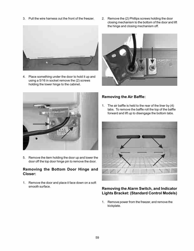
59
3. Pull the wire harness out the front of the freezer.
4. Place something under the door to hold it up andusing a 5/16 in socket remove the (2) screwsholding the lower hinge to the cabinet.
5. Remove the item holding the door up and lower thedoor off the top door hinge pin to remove the door.
Removing the Bottom Door Hinge andCloser:
1. Remove the door and place it face down on a softsmooth surface.
2. Remove the (2) Phillips screws holding the doorclosing mechanism to the bottom of the door and liftthe hinge and closing mechanism off.
Removing the Air Baffle:
1. The air baffle is held to the rear of the liner by (4)tabs. To remove the baffle roll the top of the baffleforward and lift up to disengage the bottom tabs.
Removing the Alarm Switch, and IndicatorLights Bracket: (Standard Control Models)
1. Remove power from the freezer, and remove thekickplate.

60
Removing either of the Indicator Lights:(Standard Control Models)
1. Remove power from the freezer remove theindicator lights and switch bracket anddisconnect the wires from the light that is to beremoved.
2. Press in on the tabs on the side of the light andpush the light out of the front bracket.
Removing the Alarm Switch: (StandardControl Models)
1. Remove power from the freezer, remove the lightand switch bracket and disconnect the wires fromthe switch.
2. Squeeze the locking tabs on the top and bottom ofthe switch and pushed the switch out of the front ofthe bracket.
2. Disconnect the (2) wires from the buzzer.
3. Disconnect the wiring harness that goes to the lightsand the switch.
4. Remove the (2) Phillips screws holding the bracketto the cabinet.
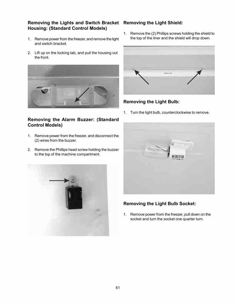
61
Removing the Lights and Switch BracketHousing: (Standard Control Models)
1. Remove power from the freezer, and remove the lightand switch bracket.
2. Lift up on the locking tab, and pull the housing outthe front.
Removing the Alarm Buzzer: (StandardControl Models)
1. Remove power from the freezer, and disconnect the(2) wires from the buzzer.
2. Remove the Phillips head screw holding the buzzerto the top of the machine compartment.
Removing the Light Shield:
1. Remove the (2) Phillips screws holding the shield tothe top of the liner and the shield will drop down.
Removing the Light Bulb:
1. Turn the light bulb, counterclockwise to remove.
Removing the Light Bulb Socket:
1. Remove power from the freezer, pull down on thesocket and turn the socket one quarter turn.

62
2. Unplug the switch from the liner and lift to switch off.
Removing the Evaporator Cover:
1. Remove power from the freezer, remove the wirebasket or baskets, on models with two basketsremove one of the upper basket glides and thebottom shelf.
2. Remove the (4) Phillips screws holding the top ofthe cover to the rear wall liner.
3. Remove the (2) Phillips screws, from the front of thecover, holding the cover to the evaporator standoffsand the (3) Phillips screws holding the cover to thebottom of the liner.
2. Disconnect the wires.
Removing the Alarm Switch Cover: (Stan-dard Control Models)
1. Squeeze the top and bottom of the cover todisengage the tabs from a liner and lift the cover off.
Removing the Alarm Switch: (StandardControl Models)
1. Remove the alarm switch cover.

63
3. Slide one side of the cover forward and remove oneof the side seal.
4. Is the model has a standard control system,unplug the wire harness from the control and liftevaporator cover out.
Removing the Electronic Control:(Standard Control Models)
1. Remove power from the freezer and remove theevaporator cover.
2. Remove the electronic control cover by disengagingthe four locking tabs holding the cover to thecontrol.
3. With the cover removed the control will pull out thefront of the evaporator cover.
Removing the Defrost Thermostat:
1. Remove power from the freezer and remove theevaporator cover.

64
2. Disconnect the wires to the thermostat and unsnapthe thermostat from the evaporator.
Removing the Defrost Heater:
1. Remove power from the freezer and remove theevaporator cover.
2. Disconnect the wires to the heater.
3. Release the (2) of aluminum straps securing theheater to the bottom of the evaporator.
4. Pull the heater down to disengaged it from theevaporator.
Removing the Evaporator Fan Assembly:
1. Remove power from the freezer and remove theevaporator cover.
2. Disconnect the wire harness from the evaporator fanmotor.
3. Using a 5/16” socket remove the (2) bolts holding thefan bracket to the liner and lift the fan assembly out.
Removing the Evaporator Fan Motor:
1. Remove power from the freezer and remove theevaporator cover.
2. Disconnect the wire harness from the evaporator fanmotor.
3. Using a 5/16” socket remove the (2) bolts holding themotor to the bracket and lift the motor out.
Removing the Evaporator Fan Blade:
1. Remove power from the freezer and remove theevaporator cover.
2. Remove the fan assembly.

65
3. Pull the fan blade off.
Note: When installing the fan blade, be sure topush it completely on.
Removing the Thermistor: (Deluxe ControlModels)
1. Remove power from the freezer and remove theevaporator cover.
2. Remove the Phillips screw holding the thermistor tothe back of the liner, then cut and splice the newthermistor into place.
Removing the Evaporator:
1. Remove power from the freezer the and removethe evaporator cover assembly.
2. Remove the defrost heater, termination thermostatand the styrofoam blocks between the evaporatorand the freezer liner
3. Recover refrigerant by using EPAapprovedrecovery system.
Note: Whenever this sealed system is opened,the filter-drier must be replaced.
CAUTION: On R-134a systems, the system mustNOT be left open to the atmospherefor more than 10 minutes to preventmoisture contamination of compressoroil.
4. Remove the filter-drier.
5. Cut the suction line at the compressor.
6. Straighten the tubing, remove the foam sleeve andcarefully feed the heat exchanger, through thecabinet, while pulling up on the evaporator.
Removing the Door Switch: (StandardControl Models)
1. Remove power from the freezer, raise the front ofthe freezer up and block it up.

66
2. Disconnect the wires from door switch.
3. Press in on the locking tab on the side of the switchand push the switch out the front.
Removing the Door Switch: (DeluxeControl Models)
1. Remove power from the freezer, raise the front ofthe freezer up and block it up.
LOCKING TAB
2. Disconnect the wires from door switch.
3. Press in on the locking tab on the side of the switchand push the switch out the front.

67
Disconnecting the Drain Hose:
1. The drain hose is pushed over the cabinet draintube and the drain pan Inlet tube. To remove thehose pull it off of the cabinet drain tube and the drainpan inlet tube.
Removing the Drain Pan:
1. Remove power from the freezer, raise the front ofthe freezer up and block it up.
2. Release a locking tab and push the drain pan upuntil it clears the spring tab on the compressor. Thenbring it forward, and lifted it out.
Removing the Filter-Drier:
1. Remove power and obtain access to the rear ofthe freezer.
CAUTION: On R-134a systems, the system mustNOT be left open to the atmosphere for
more than 10 minutes to preventmoisture contamination of compressoroil.
2. Recover refrigerant by using EPAapprovedrecovery system.
CAUTION: DO NOT un-braze old filter-drier fromsystem. This will vaporize and drivemoisture from desiccant back intosystem. The old filter-drier should becut out of system.
3. Using a three corner file score and break the tubeat the bottom of the filter-drier.
4. Remove the filter-drier by cutting the tube at the topof the filter-drier as close as possible.
Removing the Compressor Controller:
1. Remove power and obtain access to the rear ofthe freezer.

68
2. Release the plugs locking tab and disconnect thewire harness from the controller.
3. Using needle nose pliers remove the spring wireholding the controller to the compressor.
4. Pull the controller off of the compressor.
Removing the Compressor:
CAUTION: NEVER install a new compressor withoutfirst checking for possible systemcontamination.
To check for contamination, obtain oil sample from oldcompressor.
• If the oil has burned odor, but no color change orresidue — install the new compressor
• If oil has a burned odor and a sugar or gritty feel
as well as showing signs of contamination (darkcolor) — Flush The System. Remove as much ofcontamination as possible from system beforeinstalling new compressor and filter-drier.
To Flush the System:
NOTE: It is recommended that system be flushedwith dry Nitrogen. However, if refrigerantis used to flush the system you must lookat the serial plate to see what type ofrefrigerant is used in the system. This isthe only refrigerant that can be usedto flush the system and it must berecovered.
CAUTION: Use extreme care when using DryNitrogen to flush systems. Pressure innitrogen cylinder could be as high as2000 psi. Nitrogen cylinder must beequipped with approved pressureregulator and pressure relief valve.Ensure that your hoses have adequateratings for pressure involved and thatall of your equipment is in goodcondition.
CAUTION: The end of the flushing hose on thistank regulator must be equipped witha hand shut-off valve. (Robinair No.4038) Close hand shut-off valve andadjust nitrogen regulator to correctpressure before proceeding withflushing procedure.
Using Dry Nitrogen to Flush the System:
1. Remove compressor and filter-drier. Connectprocess coupling to outlet tube of condenser.
2. Fasten cloth over other end of coil to prevent old oilfrom spraying out into the room.
3. Connect hand shut-off valve on flushing hose toprocess coupling.
4. Slowly open hand shut-off valve and allow nitrogento flow through condenser until discharge is clear.
CAUTION: DO NOT exceed 300 PSIG.
5. Disconnect cap tube from evaporator. Flushevaporator in same manner as condenser.
CAUTION: DO NOT exceed 150 PSIG.

69
6. Flush cap tube. This is only possible if you haveproper service valve adaptor.
CAUTION: DO NOT exceed 300 PSIG.
7. Reassemble system.
Using Refrigerant to Flush the System:
CAUTION: Refrigerant used for flushing must berecovered into a recovery system.Meter amount of refrigerant used forflushing with your charging cylinder.DO NOT OVERFILL THE SYSTEM.
1. Disconnect the suction and discharge lines from thecompressor and remove the filter-drier. Connectprocess coupling to outlet and inlet tube ofcondenser.
2. Connect hose to outlet process coupling andcharging cylinder. Connect another hose to inletcoupling and recovery system.
3. Open charging cylinder and allow refrigerant to flowthrough condenser until discharge into bag is clear.
NOTE: To flush evaporator and heat exchanger youmust remove evaporator from insideproduct to disconnect cap tube.
4. Disconnect capillary tube from evaporator.Flush evaporator in same manner as condenser.
5. Flush cap tube. This is only possible if you haveproper service valve adaptor.
6. Reassemble system.
Installing a New Compressor:
NOTE: Entirely new compressors have beendeveloped for use with R-134a and Ester oilrefrigeration systems. Both compressorand electric motor have been modified. Oldcompressors intended for R-12 refrigerantmust not be used for new systems chargedwith R-134a.
Replacement of compressor and installation of filter-driermust be done in a continuous sequence so system isexposed to atmosphere no longer than necessary.
All replacement compressors are shipped with rubberplugs in the suction, discharge and process tubes andcontain the correct oil charge and a holding charge ofinert gas.
Compressors have a low-side process tube attached tothe compressor shell. A high-side process tube is at-tached to the filter-drier.
WARNING: DO NOT OPERATE RECIPROCATINGCOMPRESSOR WHEN CHARGINGLIQUID REFRIGERANT INTO SYSTEMTHROUGH ITS PROCESS TUBE.
Replacement compressors for appliances may have anoil cooler even if the original compressor did not. If theproduct is not equipped for an oil cooler, leave the plas-tic caps in place and install the compressor connectingonly to the suction and discharge lines of the new com-pressor.
Before installing the replacement compressor removethe discharge plug and check for the pop sound of theinert gas leaving the compressor.
CAUTION: DO NOT use compressor if you do nothear this sound.
If the compressor checks OK, reinstall the plug. Do notremove any of the plugs again until the compressor is inposition and you are ready to braze the lines.
CAUTION: On R-134a systems, compressor mustNOT be left open to atmosphere for morethan 10 minutes to prevent moisturecontamination of oil.
A new compressor which is cold (e.g. after having beenkept in a cold service van) should be left to warm to thesurrounding temperature before the plugs on the com-pressor connections are removed. This will help preventcondensation from forming in the oil and the compres-sor. Also, avoid opening the system when any of thecomponents or lines are cold.
NOTE: RELEASE holding charge (release slowly toavoid oil discharge) on new compressor toensure there is no leak in seam or tubing.Reinstall rubber plug.
1. Remove electrical power from the freezer.
2. Obtain access to the rear of the freezer
3. Recover refrigerant byusing EPAapproved recoverysystem.

70
4. Remove the controller.
5. Using a 7/16” socket remove the (4) bolts, one ineach corner, holding the compressor to the base.
6. After refrigerant is completely recovered, cutsuction and discharge lines as close to compressoras possible. Leave only enough tubing to pinch offand seal defective compressor. Plug or tape anyopensystem tubing to avoid entrance of moisture and airinto system. Remove inoperable compressor andtransfer mounting parts to new compressor.
7. Install new compressor in exact same manner asoriginal compressor.
8. Reform both suction and discharge lines to alignwith new compressor. If they are too short, useadditional lengths of tubing. Joints should overlap0.5” to provide sufficient area for good solder joint.Clean and mark area where tubing should be cut .
Cut tubing with tubing cutter. Work as quicklyas possible to avoid letting moisture and air intosystem.
Removing the Electronic Module: (DeluxeControl Models)
1. Remove power from the freezer.
2. Obtain access to the rear of the freezer.
3. Unplugged the wiring harnesses to the electronicmodule.
4. Remove the (2) Phillips screws holding the electronicmodule to the top of the machine compartment andlift electronic module out.
Removing the Main Breakers:
Note: The breakers are installed on the appliancebefore foam is added to the appliance.When the foam is added to the appliance,the foam adheres to the breakers. Whenremoving the breakers, pieces of foam maybreak off and stick to the breakers. Removeany of the larger pieces from the breakersand put them back in the cabinet.

71
Note: The edge breakers are formed so they snapand lock to the edge of the cabinet and theedge of the liner.
1. Using a regular putty knife, start at the middle of thebreaker, and carefully worked it between the cabinetand the breaker, push it as far towards insideedge to the breaker is possible. The goal is to breakthe inner flange on the underside of the breaker thatis attaching it to the cabinet. Worked the knife
toward each end, breaking through the flange is yougo.
2. Carefully peel back the breaker from the cabinettowards the inside of the unit so as to minimizethe amount of foam that sticks to the breaker. Usea putty knife to remove any large pieces of foam thatstick to the breaker and placed them back in thecabinet.
3. Repeat the process using a regular putty knife breakthe breaker flange between the inside breaker edgein the interior liner.
4. Starting in the center pull the breaker out from thefreezer, using the putty knife to separate thebreaker from the foam. Tried to remove as little ofthe foam as possible. And a large pieces of the foamthat are missing need to be replaced with additionalinsulation.
Removing the Corner Breaker:
Note: The corner breakers are flange to exceptmain breakers.
1. Remove one of the main breakers, that is attachedto the corner breaker.
2. Using a pair of pliers pull the corner breaker awayfrom the other main breaker.
Assembling the New Main Breaker and (2)New Corner Breakers:
1. Work the (2) corner breakers onto the existingbreakers.
2. Allowing the main breaker to flex in the middle andgradually work the corner breakers and the mainbreaker over the cabinet and liner flanges until theylays down smoothly.
3. Seal any joints and openings with NSF-approvesealant.
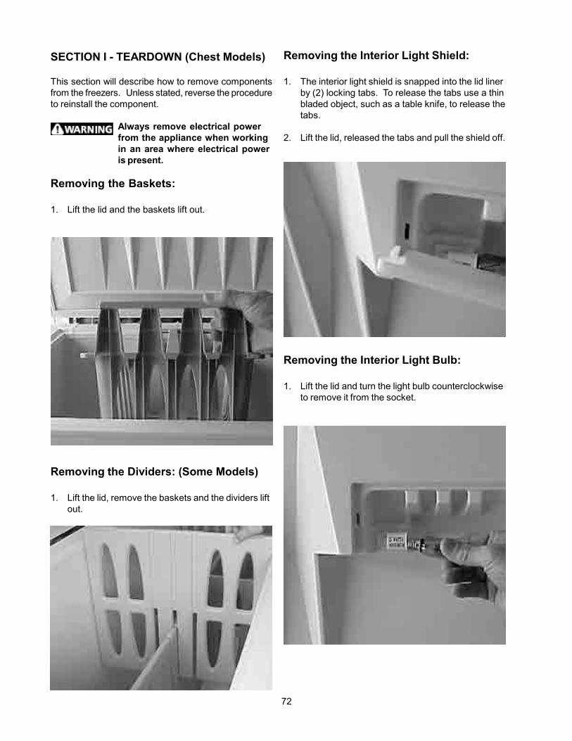
72
SECTION I - TEARDOWN (Chest Models)
This section will describe how to remove componentsfrom the freezers. Unless stated, reverse the procedureto reinstall the component.
Always remove electrical powerfrom the appliance when workingin an area where electrical poweris present.
Removing the Baskets:
1. Lift the lid and the baskets lift out.
Removing the Dividers: (Some Models)
1. Lift the lid, remove the baskets and the dividers liftout.
Removing the Interior Light Shield:
1. The interior light shield is snapped into the lid linerby (2) locking tabs. To release the tabs use a thinbladed object, such as a table knife, to release thetabs.
2. Lift the lid, released the tabs and pull the shield off.
Removing the Interior Light Bulb:
1. Lift the lid and turn the light bulb counterclockwiseto remove it from the socket.

73
Releasing the Lid:
1. Disconnect electrical power from the freezer andinsert a nail in each of the hinges to lock the hingesopen.
2. Using a 5/16” socket, remove the (4) screws, fromeach hinge, holding the upper part of the hinge tothe lid.
Note: The electrical cord, providing power to thelid is still connected.
3. Place something behind the freezer, that is aboutthe same height as the freezer, and carefully lift thelid over the hinges, turn the lid over and lay the thelid on the object.
Removing Lid Inner Liner and Seal:
The lid inner liner is held to the lid outer liner by plasticrivets and (4) Phillips head screws that are hidden in bythe seal.
Note: The number of plastic rivets will very withthe size of the freezer.
1. Disconnect electrical power from the freezer,released the lid and place it on the support withthe inner liner up.
2. Roll the seal back and using a commonscrewdriver pop-out the rivets.

74
3. Remove the (4) Phillips screws, one in each corner,holding the inner liner to the outer liner.
4. The seal will now lift off.
5. Remove the light shield and a light bulb, raise theinner liner and disconnect the wires from a lightsocket and light switch. The inner liner will now liftoff.
Removing Interior Light Socket:
1. Disconnect electrical power from the freezer and
remove the light shield and light bulb.
2. Release the lid and remove the plastic rivetsand (4) Phillips head screws holding the inner linerto the outer liner.
3. Raise the inner liner, disconnect the (2) wires fromthe socket. When reconnecting the wires be sureto connect the white wire to the terminal marked W.
4. Squeeze the (2) locking tabs and push the socketout of the liner.
Removing Interior Light Switch:
1. Disconnect electrical power from the freezer and
remove the light shield and light bulb.
2. Release the lid and remove the plastic rivetsand (4) Phillips head screws holding the inner linerto the outer liner.
3. Raise the inner liner and disconnect the two wiresfrom the switch.

75
4. Release the locking tab and push the socketout of the liner.
Removing Lid Handle:
1. Disconnect electrical power from the freezer andrelease the inner lid liner.
2. Remove the insulation from the lid panel.
3. Using a 1/2” wrench remove the (2) nuts holding thehandle to the panel.
4. Remove the permagum sealing the wire harnessopening.
Note: Always replace the permagum whenreinstalling the handle.
5. Insert a common screwdriver between the panel andthe bottom of the handle and pull the handle out, soit clears the face of the locking mechanism.

76
3. Unplug the wire harness from the board.
Removing Lock Latch:
1. Disconnect electrical power from the freezer andrelease of the inner lid liner.
2. Pull the insulation back, remove the Phillips screwholding the latch to the locking mechanism and liftthe latch off.
Removing Locking Mechanism:
1. Disconnect electrical power from the freezer andremove of the lid handle.
2. Remove the latch arm.
6. Push down on the plastic studs to release the handlefrom the liner.
Removing Interface Board:
1. Disconnect electrical power from the freezer andremove the lid handle.
2. Using a #1 Phillips remove the (2) screws holdingthe board to the handle and lift the board out.

77
3. Using a common screwdriver release the locking forkand push the locking mechanism out the front of thepanel.
Removing Outer Lid Panel:
1. Disconnect electrical power from the freezer andremove the inner lid liner.
2. Remove the insulation, lid handle and the lockingmechanism.
3. Disconnect the wiring harness from interface boardand , the green ground wire from the panel.
4. Using a common screwdriver work the wiring gromitinto the outer lid panel and remove the harness.
5. The outer panel can now be removed.
Removing the Hinges:
1. While holding in on the bottom part of the hinge,use a 5/16 “ socket, to remove the (4) screwsholding the bottom part of the hinge to the freezer.
2. Slowly release the pressure from the bottom part ofthe hinge.
3. While holding the hinge, use a 5/16 “ socket, toremove the (4) screws holding the hinge to the lidand lift the hinge off.

78
Removing the Hinges: (Alternate Method)
1. With the lid closed insert a pin or nail into the hingeto lock it closed.
2. Using a 5/16” socket remove the (4) screws holdingthe hinge to the lid and the (4) screws holding thehinge to the chassis.
Replacing the Breaker Trim:
When the freezer is manufactured, the trim and end capsare installed before foam is added to the freezer. Whenfoam is added to the freezer, some of the foam adheresto the trim and caps, helping to hold them in place. Whena piece of trim or an end cap is removed, some of thefoam will come with it. If the trim or end cap is to bereused the foam must be cleaned off.
The outer liner of the cabinet has a 3/16” flange and theinner liner has (2) grooves in it.
The trim has a channel with a locking tab that snapsdown over the inner liner and a flange with a locking tabthat snaps under the flange of the outside liner.
The end caps are formed to allow the trim to slide intothem.
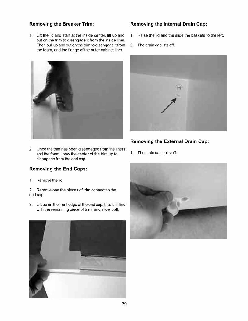
79
Removing the Internal Drain Cap:
1. Raise the lid and the slide the baskets to the left.
2. The drain cap lifts off.
Removing the External Drain Cap:
1. The drain cap pulls off.
Removing the Breaker Trim:
1. Lift the lid and start at the inside center, lift up andout on the trim to disengage it from the inside liner.Then pull up and out on the trim to disengage it fromthe foam, and the flange of the outer cabinet liner.
2. Once the trim has been disengaged from the linersand the foam, bow the center of the trim up todisengage from the end cap.
Removing the End Caps:
1. Remove the lid.
2. Remove one the pieces of trim connect to theend cap.
3. Lift up on the front edge of the end cap, that is in linewith the remaining piece of trim, and slide it off.

80
Removing the Cold Control Knob:
1. The cold control knob pulls off.
Releasing the Machine CompartmentCover:
1. Disconnect electrical power.
2. Remove the (2) Phillips screws holding themachine compartment cover to the outer liner.
3. Pull out on the top of the cover.
Removing the Cold Control:
1. Disconnect power and release the machinecompartment cover.
2. Disconnect the wire harness to the cold control.
3. Push down on the control to release thespring-loaded tabs from the machine compartmentcover and lift the control out.
Removing the Machine CompartmentCover:
1. Disconnect power and release the machinecompartment cover.

81
2. Release the cold control and lift the cover out of theslots.
Removing the Thermistor:
1. Disconnect power and release the machinecompartment cover.
2. Remove the permagum from the base of the tube inwhich the thermistor is inserted.
3. Pull the thermistor out of the tube.
Note: When replacing the thermistor, cut andsplice the new thermistor into the circuit.
Removing the Electronic Module:
1. Disconnect power and remove the machinecompartment cover.
2. Unplug the wire harnesses from the module.
3. Remove the (2) Phillips screws holding the moduleto the back wall of the machine compartment andlift the module out.

82
Removing the Run Capacitor andController Assembly:
1. Disconnect electrical power and remove themachine compartment cover.
2. Unplugged the wires from the controller andrelease the spring wire clip holding the runcapacitor and controller assembly to thecompressor.
3. Pull the controller off of the compressor and slidethe capacitor off of the controller.
Removing the Filter-Drier:
1. Disconnect power from the freezer and remove themachine compartment cover.
CAUTION: On R-134a systems, the system mustNOT be left open to the atmosphere formore than 10 minutes to preventmoisture contamination of compressoroil.
2. Recover refrigerant by using EPAapprovedrecovery system.
CAUTION: DO NOT un-braze old filter-drier fromsystem. This will vaporize and drivemoisture from desiccant back intosystem. The old filter-drier should becut out of system.
3. Using a three corner file score and break the tubeat the bottom of the filter-drier.
4. Remove the filter-drier by cutting the tube at the topof the filter-drier as close as possible.
Replacing the Compressor:
CAUTION: NEVER install a new compressor withoutfirst checking for possible systemcontamination.

83
To check for contamination, obtain oil sample from oldcompressor.
• If the oil has burned odor, but no color change orresidue — install the new compressor
• If oil has a burned odor and a sugar or gritty feelas well as showing signs of contamination (darkcolor) — Flush The System. Remove as much ofcontamination as possible from system beforeinstalling new compressor and filter-drier.
To Flush the System:
NOTE: It is recommended that system be flushedwith dry Nitrogen. However, if refrigerantis used to flush the system you must lookat the serial plate to see what type ofrefrigerant is used in the system. This isthe only refrigerant that can be usedto flush the system and it must berecovered.
CAUTION: Use extreme care when using DryNitrogen to flush systems. Pressure innitrogen cylinder could be as high as2000 psi. Nitrogen cylinder must beequipped with approved pressureregulator and pressure relief valve.Ensure that your hoses have adequateratings for pressure involved and thatall of your equipment is in goodcondition.
CAUTION: The end of the flushing hose on thistank regulator must be equipped witha hand shut-off valve. (Robinair No.4038) Close hand shut-off valve andadjust nitrogen regulator to correctpressure before proceeding withflushing procedure.
Using Dry Nitrogen to Flush the System:
1. Remove compressor and filter-drier. Connectprocess coupling to outlet tube of condenser.
2. Fasten cloth over other end of coil to prevent old oilfrom spraying over room.
3. Connect hand shut-off valve on flushing hose toprocess coupling.
4. Slowly open hand shut-off valve and allow nitrogento flow through condenser until discharge is clear.
CAUTION: DO NOT exceed 300 PSIG.
5. Reassemble system.
Using Refrigerant to Flush the System:
CAUTION: Refrigerant used for flushing must berecovered into a recovery system.Meter the amount of refrigerant used forflushing with your charging cylinder.DO NOT OVERFILL THE SYSTEM.
1. Disconnect the suction and discharge lines from thecompressor and remove the filter-drier. Connectprocess coupling to outlet and inlet tube ofcondenser.
2. Connect hose to outlet process coupling andcharging cylinder. Connect another hose to inletcoupling and recovery system.
3. Open charging cylinder and allow refrigerant to flowthrough condenser until discharge into bag is clear.
4. Reassemble system.
Installing a New Compressor:
NOTE: Entirely new compressors have beendeveloped for use with R-134a and Ester oilrefrigeration systems. Both compressor andelectric motor have been modified. Oldcompressors intended for R-12 refrigerantmust not be used for new systems chargedwith R-134a.
Replacement of compressor and installation of filter-driermust be done in a continuous sequence so system isexposed to atmosphere no longer than necessary.
All replacement compressors are shipped with rubberplugs in the suction, discharge and process tubes andcontain the correct oil charge and a holding charge ofinert gas.
Compressors have a low-side process tube attached tothe compressor shell. A high-side process tube is at-tached to the filter-drier.
WARNING: DO NOT OPERATE RECIPROCATINGCOMPRESSOR WHEN CHARGINGLIQUID REFRIGERANT INTO SYSTEMTHROUGH ITS PROCESS TUBE.

84
Replacement compressors for freezer may have an oilcooler even if the original compressor did not. If the prod-uct is not equipped for an oil cooler, leave the plasticcaps in place and install the compressor connecting onlyto the suction and discharge lines of the newcompressor.
Before installing the replacement compressor removethe discharge plug and check for the pop sound of theinert gas leaving the compressor.
CAUTION: DO NOT use compressor if you do nothear this sound.
If the compressor checks OK, reinstall the plug. Do notremove any of the plugs again until the compressor is inposition and you are ready to braze the lines.
CAUTION: On R-134a systems, compressor mustNOT be left open to atmosphere for morethan 10 minutes to prevent moisturecontamination of oil.
A new compressor which is cold (e.g. after having beenkept in a cold service van) should be left to warm to thesurrounding temperature before the plugs on the com-pressor connections are removed. This will help preventcondensation from forming in the oil and the compres-sor. Also, avoid opening the system when any of thecomponents or lines are cold.
NOTE: RELEASE holding charge (release slowly toavoid oil discharge) on new compressor toensure there is no leak in seam or tubing.Reinstall rubber plug.
1. Disconnect electrical supply to freezer.
2. Remove machine compartment panel.
3. Recover refrigerant byusing EPAapproved recoverysystem.
4. Remove the controller and run capacitor from thecompressor and unplug the ground wire.
6. Remove mounting clips and washers.
7. After refrigerant is completely recovered, cutsuction and discharge lines as close to compressoras possible. Leave only enough tubing to pinch offand seal defective compressor. Plug or tape anyopensystem tubing to avoid entrance of moisture and airinto system. Remove inoperable compressor andtransfer mounting parts to new compressor.
8. Install new compressor in exact same manner asoriginal compressor.
9. Reform both suction and discharge lines to alignwith new compressor. If they are too short, useadditional lengths of tubing. Joints should overlap0.5” to provide sufficient area for good solder joint.Clean and mark area where tubing should be cut.Cut tubing with tubing cutter. Work as quickly aspossible to avoid letting moisture and air intosystem.

85
NOTE: If low-side process tube is too short, silversolder four inch piece of tubing ontoprocess tube at this time.
10. Solder all connections.
13. Replace the original filter-drier.
CAUTION: DO NOT un-braze old filter-drier fromsystem. This will vaporize and drivemoisture from desiccant back intosystem. The old filter-drier should becut out of system.
15. Evacuate and charge system using recommendedprocedure described under Evacuating andRecharging.
Replacing the Condenser:
The condenser is foamed in place and is not accessiblefor repair. However, repair can be made by installing aservice replacement condenser kit. Refer to the appro-priate part list of the model been service for the correctkit part number.
Each service replacement condenser kit consists of: acondenser assembly that can be installed on the backof the cabinet, mounting hardware, replacement filter-drier and a complete installation instructions.
To install, use the following procedure:
1. Disconnect unit from source of power.
2. Recover refrigerant byusing EPAapproved recoverysystem.
3. Installed the replacement condenser in accordancewith the instructions included with the kit.
4 Evacuate and charge a system using therecommended procedure described underevacuation and recharging found in section D.

86
NOTES

87
NOTES

88