Embed Size (px)
Citation preview
Friction Devices
Q. 5.1. (a) Define brake.
Ans. A brake is a device used for retarding or stopping the motion of a body. When
we apply brakes a frictional resistance acts on the body the kinetic energy of the body is
dissipated in the form of heat.
Q. 5.1. (b) Define dynamometer.
Ans. A dynamometer is a device for measuring the mechanical power developed by a machine.
Dynamorneter applies the frictional resistance and has an arrangement to measure the resistance
applied. By knowing the resistance applied the power can be calculated.
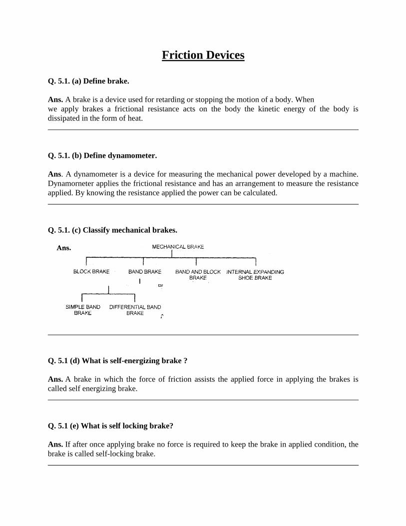
Q. 5.1. (c) Classify mechanical brakes.
Q. 5.1 (d) What is self-energizing brake ?
Ans. A brake in which the force of friction assists the applied force in applying the brakes is
called self energizing brake.
Q. 5.1 (e) What is self locking brake?
Ans. If after once applying brake no force is required to keep the brake in applied condition, the
brake is called self-locking brake.
SECTION—B
Q. 5.2 (a) Differentiate between absorption dynamometer and transmission dynamometer.
Ans. In absorption dynamometer,the power to be measured is absorbed in doing work against the
frictional resistance applied and is dissipated in the form of heat
A transmission dynamornetei measure the poi er which is being transmittcd The power bemg
measured is not dissipated in the form of heat g the power while being transmitted from steam
turbine is the ship impeller can be measured by transmission dynamometer.
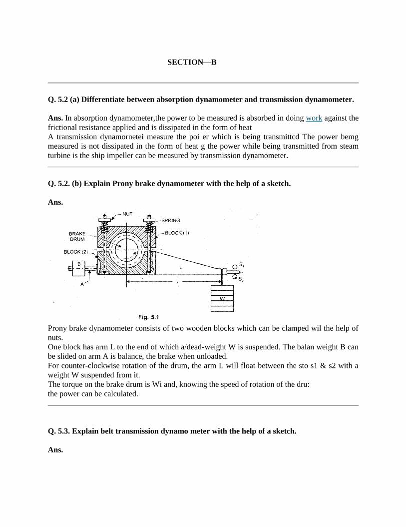
Q. 5.2. (b) Explain Prony brake dynamometer with the help of a sketch.
Ans.
Prony brake dynamometer consists of two wooden blocks which can be clamped wil the help of
nuts.
One block has arm L to the end of which a/dead-weight W is suspended. The balan weight B can
be slided on arm A is balance, the brake when unloaded.
For counter-clockwise rotation of the drum, the arm L will float between the sto s1 & s2 with a
weight W suspended from it.
The torque on the brake drum is Wi and, knowing the speed of rotation of the dru:
the power can be calculated.
Q. 5.3. Explain belt transmission dynamo meter with the help of a sketch.
Ans.
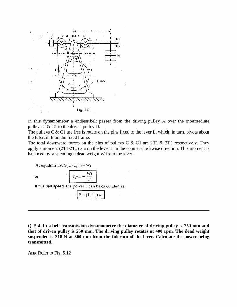
In this dynamometer a endless.belt passes from the driving pulley A over the intermediate
pulleys C & C1 to the driven pulley D.
The pulleys C & C1 are free is rotate on the pins fixed to the lever L, which, in turn, pivots about
the fulcrum E on the fixed frame.
The total downward forces on the pins of pulleys C & C1 are 2T1 & 2T2 respectively. They
apply a moment (2T1-2T.,) x a on the lever L in the counter clockwise direction. This moment is
balanced by suspending a dead weight W from the lever.
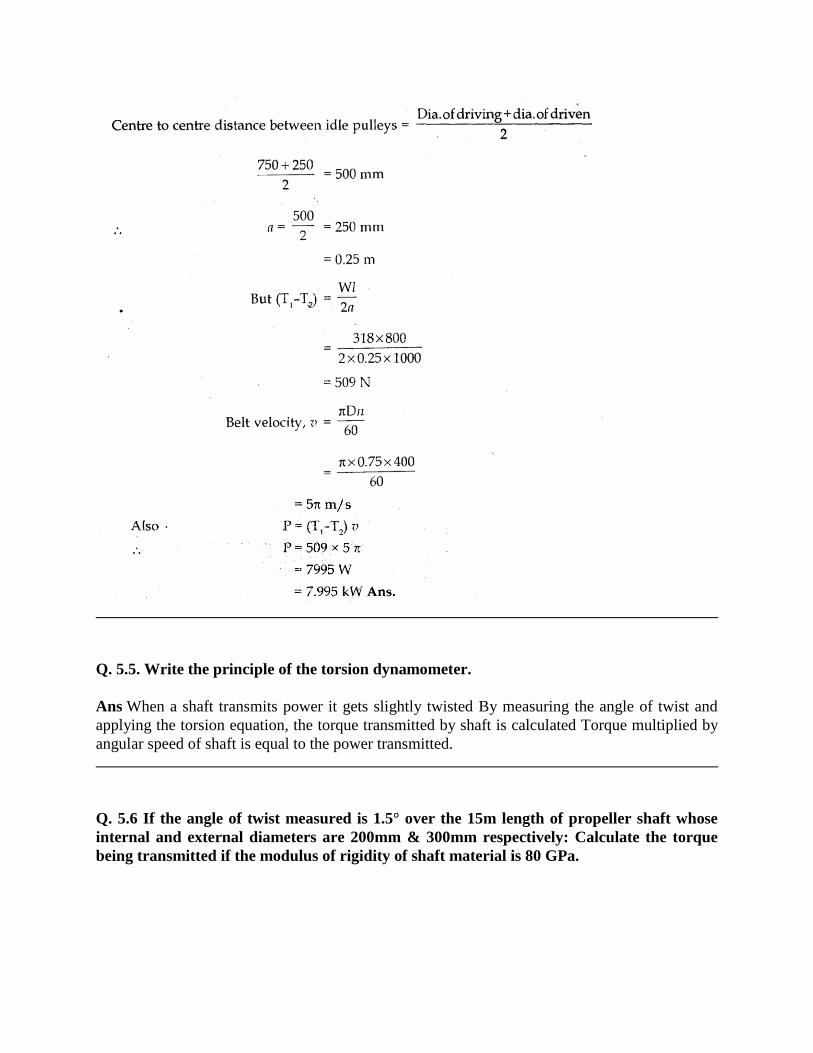
Q. 5.4. In a belt transmission dynamometer the diameter of driving pulley is 750 mm and
that of driven pulley is 250 mm. The driving pulley rotates at 400 rpm. The dead weight
suspended is 318 N at 800 mm from the fulcrum of the lever. Calculate the power being
transmitted.
Ans. Refer to Fig. 5.12
Q. 5.5. Write the principle of the torsion dynamometer.
Ans When a shaft transmits power it gets slightly twisted By measuring the angle of twist and
applying the torsion equation, the torque transmitted by shaft is calculated Torque multiplied by
angular speed of shaft is equal to the power transmitted.
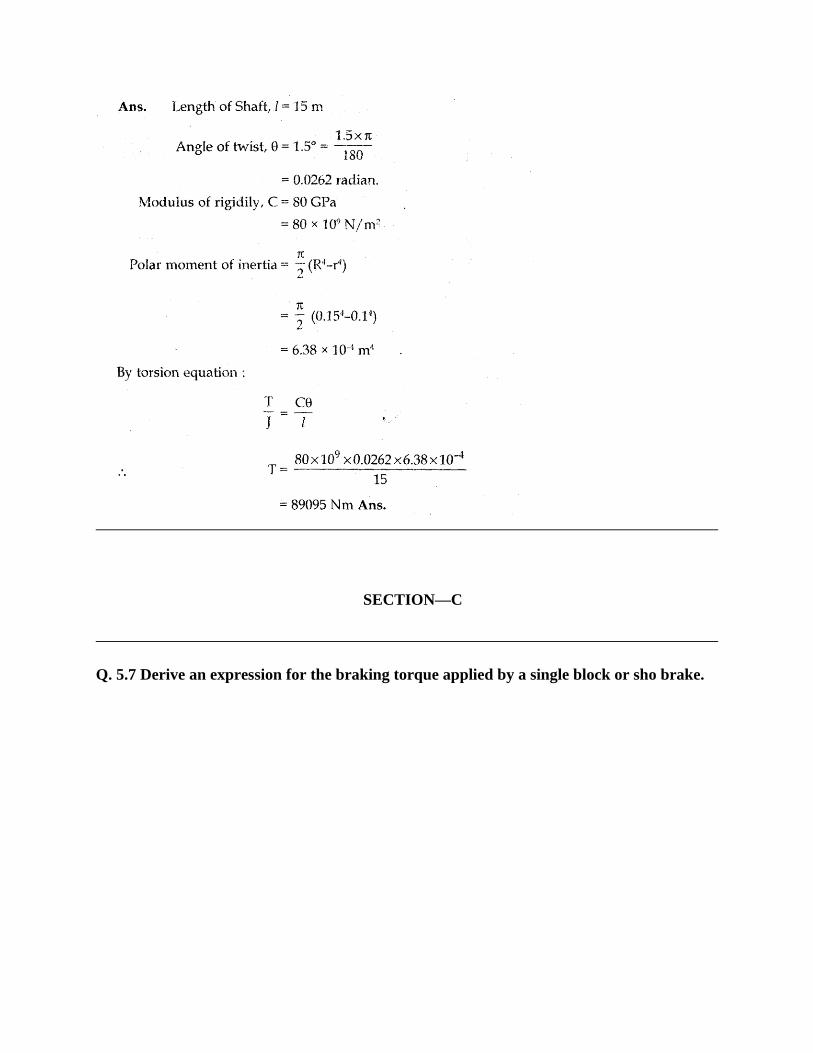
Q. 5.6 If the angle of twist measured is 1.5° over the 15m length of propeller shaft whose
internal and external diameters are 200mm & 300mm respectively: Calculate the torque
being transmitted if the modulus of rigidity of shaft material is 80 GPa.
SECTION—C
Q. 5.7 Derive an expression for the braking torque applied by a single block or sho brake.
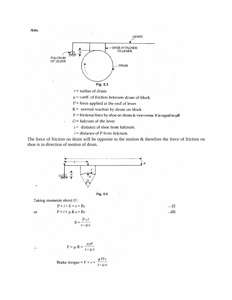
The force of friction on drum will be opposite to the motion & therefore the force of friction on
shoe is in direction of motion of drum.
Note (a) : — From equation (i), we see that moment F a gets added to moment P x of the applied
force. Thus the frictional force helps the applied force in applying the brake. Such type of brake
is called self energizing brake.
Note (b) :-- From equation (ii), P = R (s - tin), therefore if s ha, no force will be required to the
keep the brake applied. This type of brake is called self locking brake.
Note (c) :— In the above equations t’ will have to be used in place of j.t if the angle 20
subtended by the shoe is > 400.
Q. 5.9 A bicycle and rider travelling at 12 knVhr on a level ground have a mass of 105 kg.
A brake is applied to the rear wheel which is 800 mm in diameter. The pressure applied on
the brake is 80 N and the coefficient of friction 0.06. Find the distance covered by the
bicycle and the number of turns of its wheel before the cycle comes to rest
Ans. Normal reaction, R = 80 N
p = 0.06
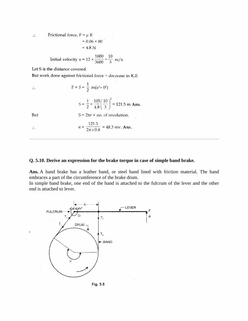
Q. 5.10. Derive an expression for the brake torque in case of simple band brake.
Ans. A band brake has a leather band, or steel band lined with friction material. The band
embraces a part of the circumference of the brake drum.
In simple band brake, one end of the band is attached to the fulcrum of the lever and the other
end is attached to lever.
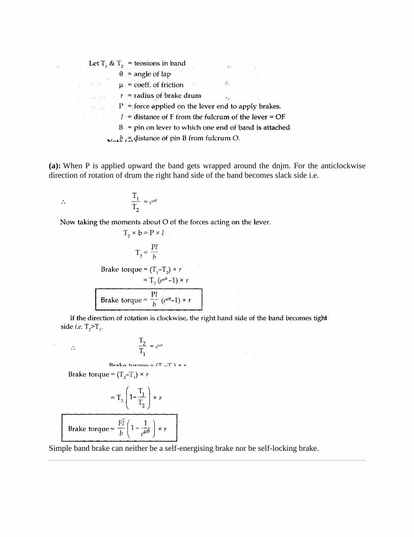
(a): When P is applied upward the band gets wrapped around the dnjm. For the anticlockwise
direction of rotation of drum the right hand side of the band becomes slack side i.e.
Simple band brake can neither be a self-energising brake nor be self-locking brake.
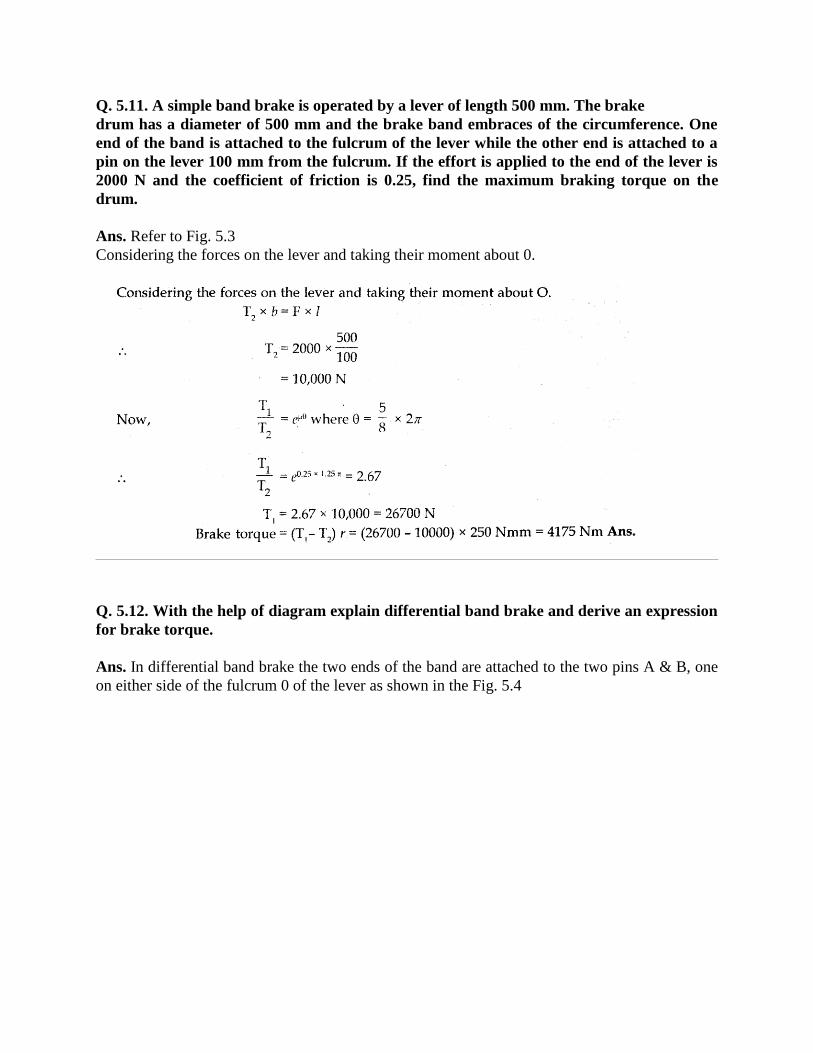
Q. 5.11. A simple band brake is operated by a lever of length 500 mm. The brake
drum has a diameter of 500 mm and the brake band embraces of the circumference. One
end of the band is attached to the fulcrum of the lever while the other end is attached to a
pin on the lever 100 mm from the fulcrum. If the effort is applied to the end of the lever is
2000 N and the coefficient of friction is 0.25, find the maximum braking torque on the
drum.
Ans. Refer to Fig. 5.3
Considering the forces on the lever and taking their moment about 0.
Q. 5.12. With the help of diagram explain differential band brake and derive an expression
for brake torque.
Ans. In differential band brake the two ends of the band are attached to the two pins A & B, one
on either side of the fulcrum 0 of the lever as shown in the Fig. 5.4
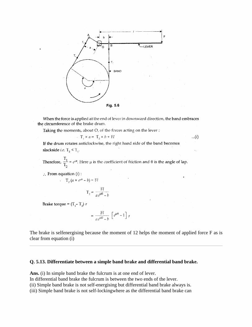
The brake is selfenergising because the moment of 12 helps the moment of applied force F as is
clear from equation (i)
Q. 5.13. Differentiate between a simple band brake and differential band brake.
Ans. (i) In simple band brake the fulcrum is at one end of lever.
In differential band brake the fulcrum is between the two ends of the lever.
(ii) Simple band brake is not self-energising but differential band brake always is.
(iii) Simple band brake is not self-lockingwhere as the differential band brake can
be.
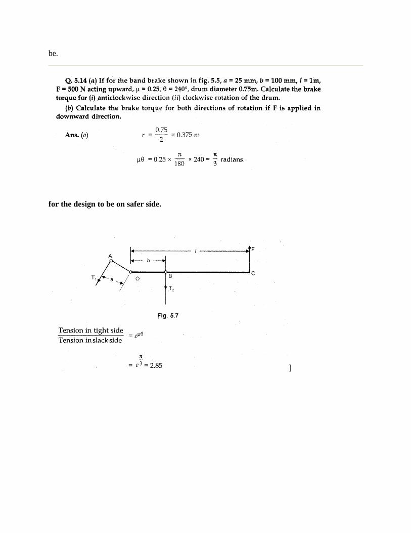
for the design to be on safer side.
]
(b) If F is applied downward at end C of the lever, the downward movement of pin B will be
greater than the upward moment of pin A, therefore the band will move away from the drum and
thus no brake torque will act on the drum.
Q. 5.15. What is the difference between a brake and a dynamometer?
Ans. A dynamometer is used for measuring the power developed by a machine and therefore has
the arrangement to measure the resistant applied to the motion of the machine. It is not used to
slow down or stop the machine.
A brake is used to slow down or stop the motion of a body. It need not have any measuring
arrangement to know the resistance applied to the motion of the body.
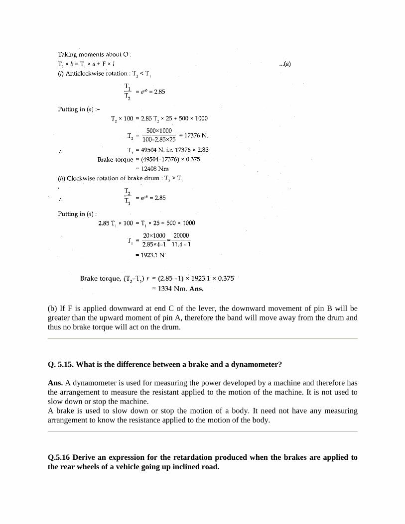
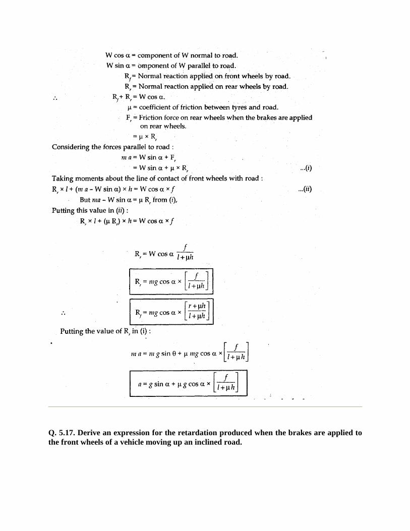
Q.5.16 Derive an expression for the retardation produced when the brakes are applied to
the rear wheels of a vehicle going up inclined road.
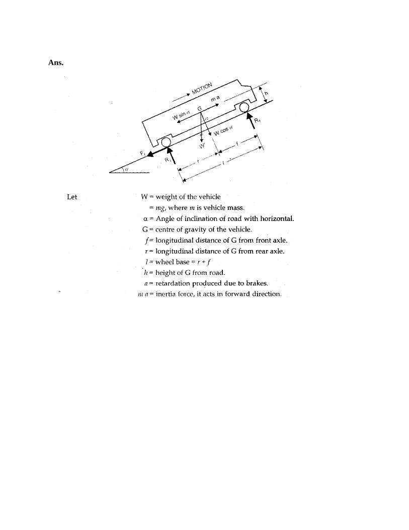
Ans.
Q. 5.17. Derive an expression for the retardation produced when the brakes are applied to
the front wheels of a vehicle moving up an inclined road.
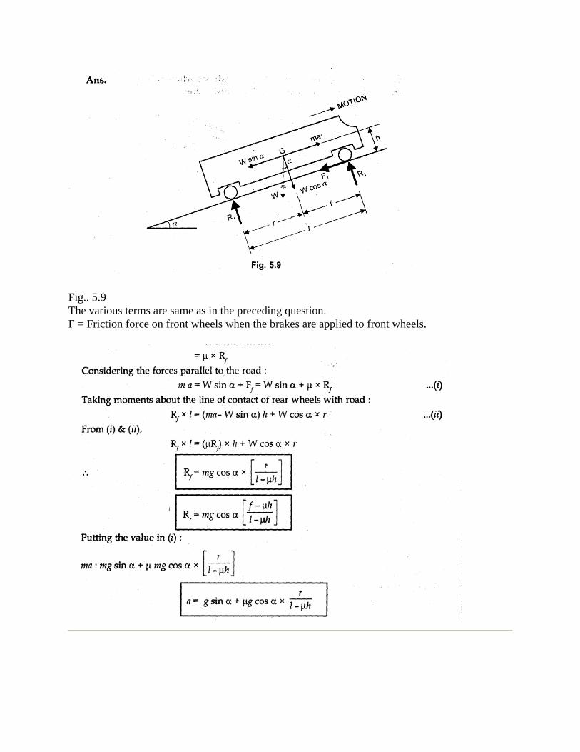
Fig.. 5.9
The various terms are same as in the preceding question.
F = Friction force on front wheels when the brakes are applied to front wheels.
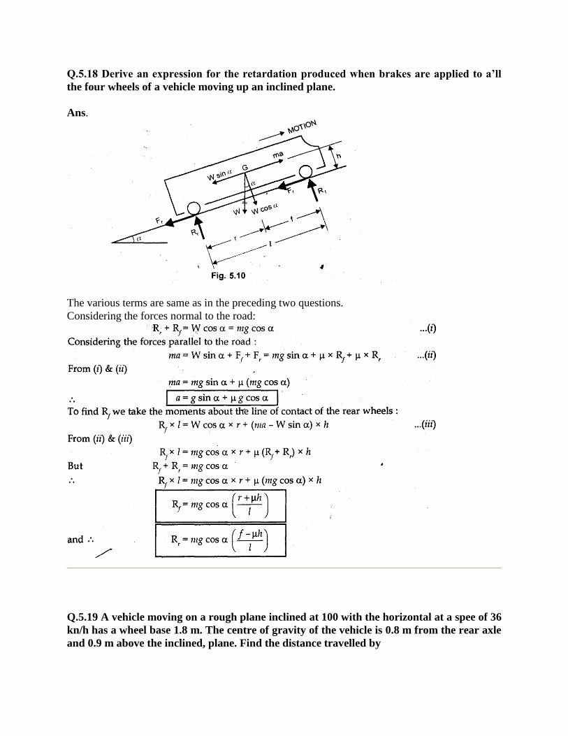
Q.5.18 Derive an expression for the retardation produced when brakes are applied to a’ll
the four wheels of a vehicle moving up an inclined plane.
Ans.
The various terms are same as in the preceding two questions.
Considering the forces normal to the road:
Q.5.19 A vehicle moving on a rough plane inclined at 100 with the horizontal at a spee of 36
kn/h has a wheel base 1.8 m. The centre of gravity of the vehicle is 0.8 m from the rear axle
and 0.9 m above the inclined, plane. Find the distance travelled by
the vehicle before connected to rest and the time taken to do sohen the vehicle moves up
the plane.
The brakes are applied to a1lthe four wheels and the coefficient of friction is 0.5.
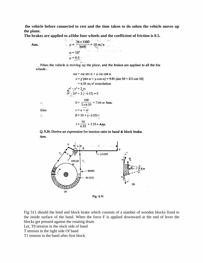
Fig 511 should the bind and block brake which consists of a number of wooden blocks fixed to
the inside surface of the band. When the force F is applied downward at the end of lever the
blocks get pressed against the rotating drum
Let, T0 tension in the slack side of band
T tension in the tight side Of band
T1 tension in the band after first block
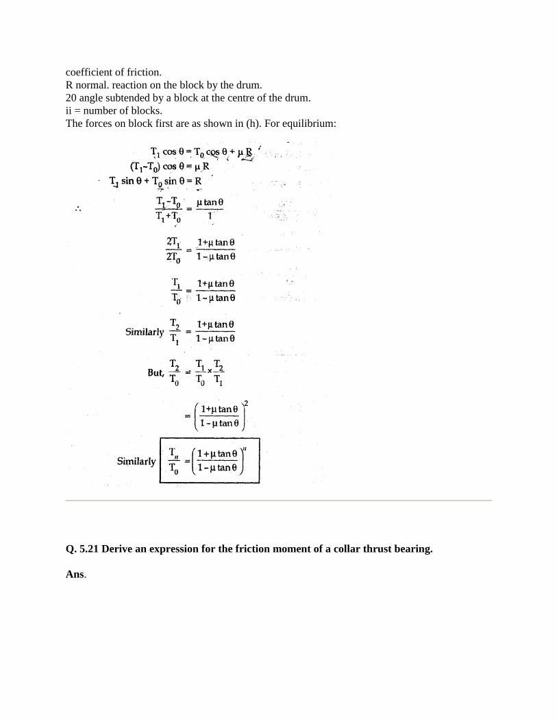
coefficient of friction.
R normal. reaction on the block by the drum.
20 angle subtended by a block at the centre of the drum.
ii = number of blocks.
The forces on block first are as shown in (h). For equilibrium:
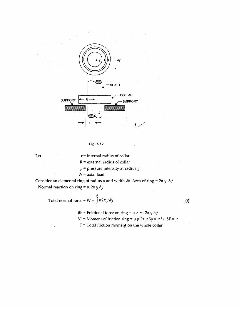
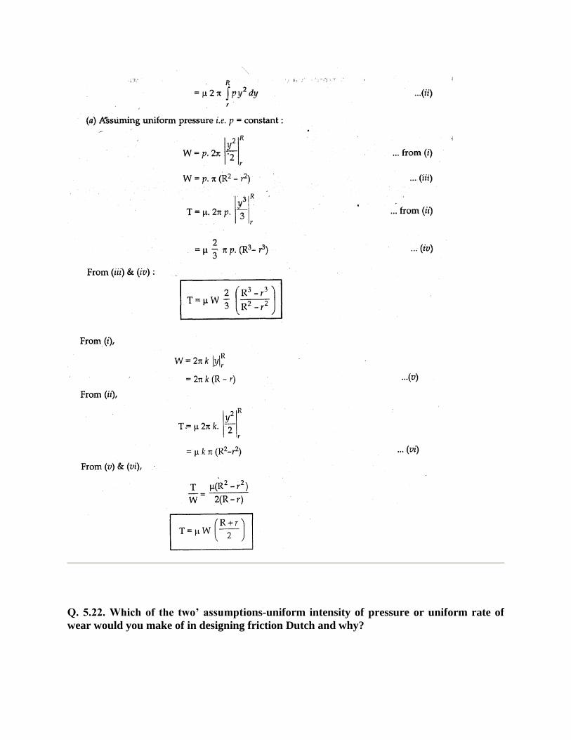
Q. 5.21 Derive an expression for the friction moment of a collar thrust bearing.
Ans.
Q. 5.22. Which of the two’ assumptions-uniform intensity of pressure or uniform rate of
wear would you make of in designing friction Dutch and why?
Ans I. designing a friction clutch, the assumption of uniform use of Because if clutch is designed
by ass uniform the clutch will able to transmitter ujavke been designed even if the intensity of
pressure is uniform. In this way the design is on safe side.’
Q. 5.23. Differentiate between theory of uniform .pressure and theory of uniform wear.
Ans. The assumption of uniform hold good-with newly fitted leaning surfaces where
the surfaces is assumed tobe perfect. But as the wear depends
upon the velocity and r intensity therefore the wear will not be uniform, therefore, as the slft Is
run or sometime the 5resure distribution will remain uniform
According to the assumption of uniform-pressure goes on decreasing radically
outward because velocity goes on ñcreksi1ig2iia11Loutward. ‘
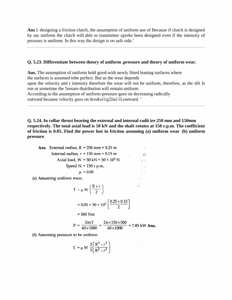
Q. 5.24. In collar thrust bearing the external and internal radii ire 250 mm and 150mm
respectively. The total axial load is 50 kN and the shaft rotates at 150 r.p.m. The coefficient
of friction is 0.05. Find the power lost in friction assuming (a) uniform wear (b) uniform
pressure.
Note : From the question 5.24, it is clear that friction torque is less if wear is assumed to be
constant. Therefore,. in design of clutch the wear is assumed to be uniform
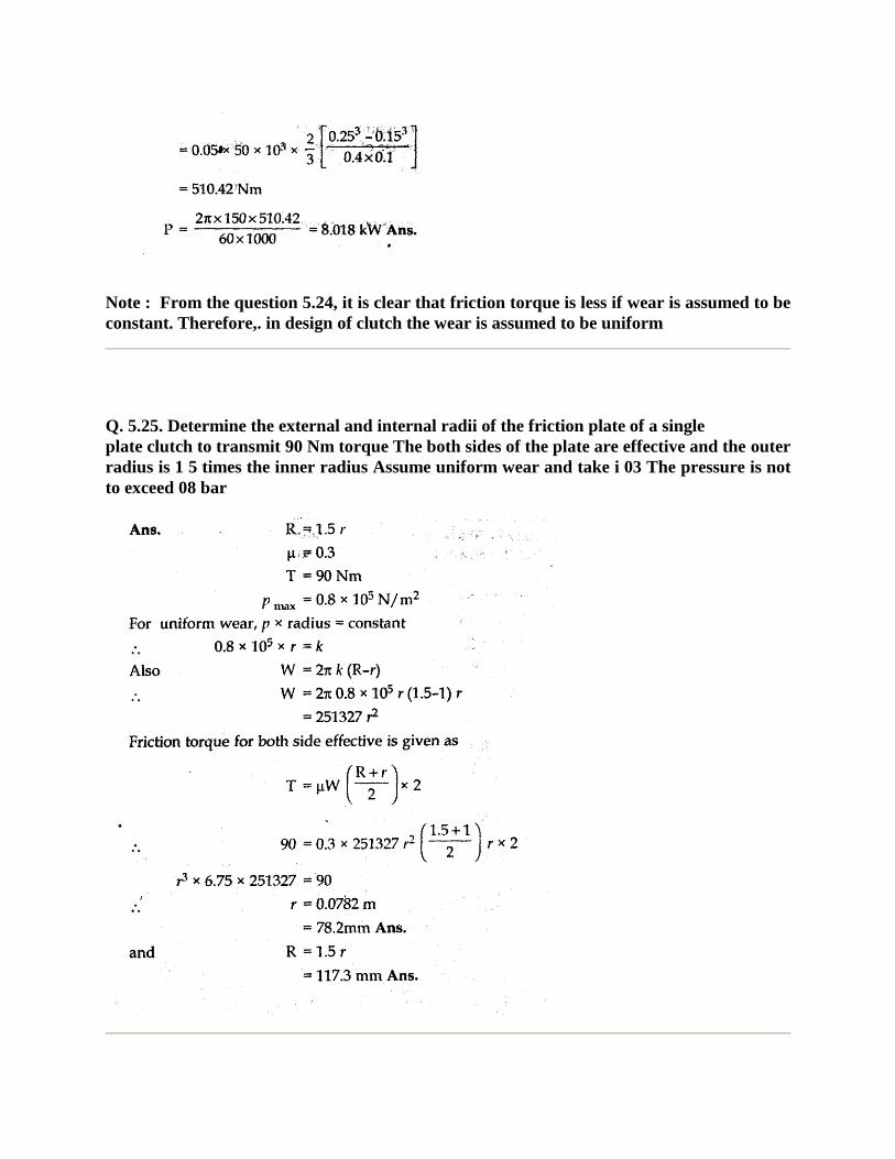
Q. 5.25. Determine the external and internal radii of the friction plate of a single
plate clutch to transmit 90 Nm torque The both sides of the plate are effective and the outer
radius is 1 5 times the inner radius Assume uniform wear and take i 03 The pressure is not
to exceed 08 bar
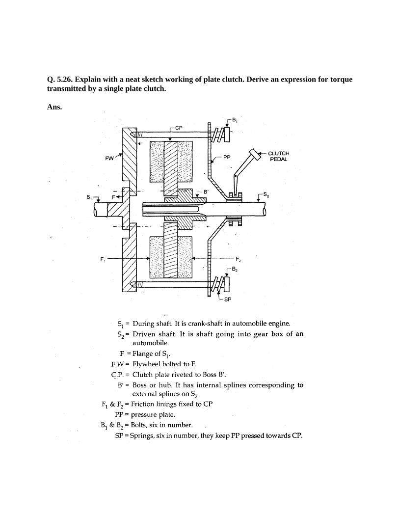
Q. 5.26. Explain with a neat sketch working of plate clutch. Derive an expression for torque
transmitted by a single plate clutch.
Ans.
Working: The springs keep the pressure plate pressed towards clutch plate. Due to this the clutch
plate remains san4-wiched between pressure plate and flywheel. Therefore when the shaft S1
rotates, the clutch plate also rotate with FW & PP. Thus power is transmitted from to S2.
When pedal is pressed, the PP moves towards right hand side, the CP becomes free and therefore
stops rotating. Thus power is stopped from going to shaft 2•
For derivation please see 5.21. The torque will be double of the torque of collar because in single
plate clutch there are two pairs of friction surfaces
.
Q. 5.27. What are thick & thin film lubrications?
Ans. If lubricant layerS is of finite thickness, so that no actual contact takes place between the
surfaces, the friction is determined by the viscosity of lubricant. It is thick film lubrication.
If the layer is only a few molecules thick, the friction is determined by the oiliness of the
lubricant. It is thin film lubrication.
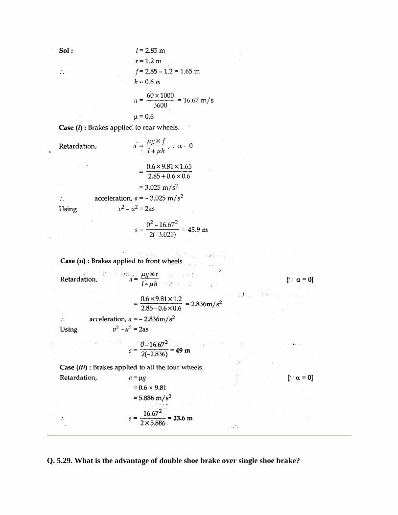
Q. 5.28. A vehicle having a wheel base 2.85 m, has its centre of mass 1.2 from the rear axle
and 600 mm above ground. It moves on a level road at a speed of 60 knVhr. Determine the
distance moved by the vehicle before coming to rest on applying the brakes (i) to the rear
wheels, (ii) to the front wheels (iii) to all the four wheels. Take = 0.6
Q. 5.29. What is the advantage of double shoe brake over single shoe brake?
Ans. Single shoe when pressed against the brake drum, produces side thrust on the bearings of
the shaft of the drum.
But in case of double shoe brake, the two shoes presses the drum in opposite direction, therefore
there is no side thrust.
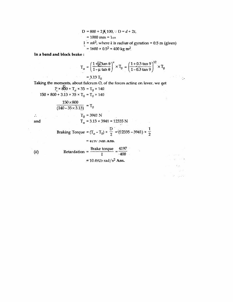
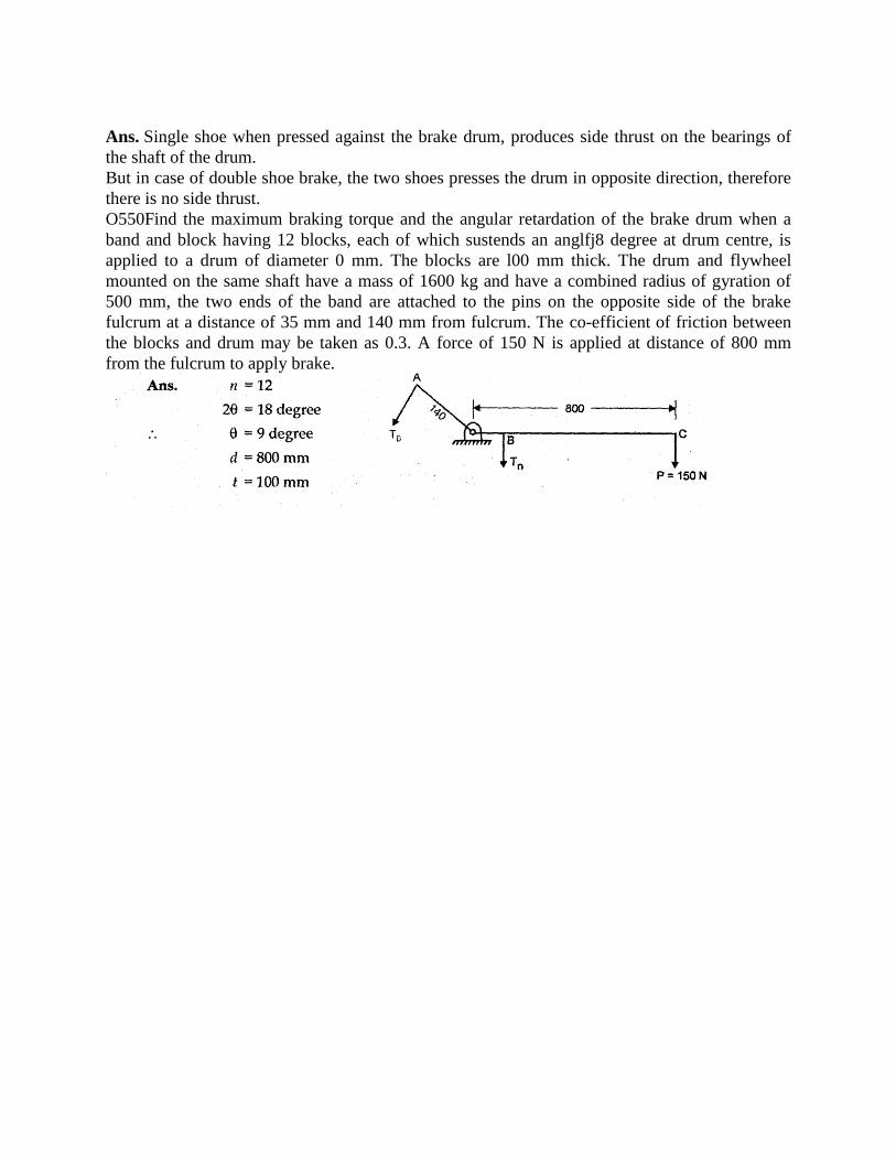
O550Find the maximum braking torque and the angular retardation of the brake drum when a
band and block having 12 blocks, each of which sustends an anglfj8 degree at drum centre, is
applied to a drum of diameter 0 mm. The blocks are l00 mm thick. The drum and flywheel
mounted on the same shaft have a mass of 1600 kg and have a combined radius of gyration of
500 mm, the two ends of the band are attached to the pins on the opposite side of the brake
fulcrum at a distance of 35 mm and 140 mm from fulcrum. The co-efficient of friction between
the blocks and drum may be taken as 0.3. A force of 150 N is applied at distance of 800 mm
from the fulcrum to apply brake.