Embed Size (px)
Citation preview

Freedom XDS Calibration Manual
P/N SG07230041
REVISION A
REV DATE 08/09/14
THIS DRAWING IS COPYRIGHTED AND IS THE PROPERTY OF CERTIFIED POWER INC.
Des Moines, IA (800) 333‐7411 Bridgeton, MO (800) 999‐7411
Burnsville, MN (800) 289‐1330 Perrysburg, OH (800) 374‐7411
Mundelein, IL (888) 905‐7411

Freedom XDS Calibration Manual: SG07230041
Certified Power Inc. Page 2
DocumentRevisionHistoryREVISION DATE DESCRIPTION
A 08/09/14 INITIAL RELEASE
PurposeThis manual is a guide to assist in calibration of the Freedom XDS (FXDS) spreader control system. This manual
leads the user through a step‐by‐step setup process for several given application examples. Items covered in
this manual include:
1. Setup of materials
2. Measured Dump Procedures (Auger calibration)
3. Spinner calibration
4. Gate calibration
5. Speedometer Calibration

Freedom XDS Calibration Manual: SG07230041
Certified Power Inc. Page 3
ContentsDocument Revision History ................................................................................................................................. 2
Purpose ................................................................................................................................................................ 2
Getting Started .................................................................................................................................................... 5
Technician’s Overview ......................................................................................................................................... 5
Logging In ......................................................................................................................................................... 5
F.I.R.S.T. ........................................................................................................................................................... 5
Date/Time ........................................................................................................................................................ 6
Truck ID ............................................................................................................................................................ 6
Units (Imperial‐US/Metric) .............................................................................................................................. 6
Calibration ........................................................................................................................................................... 7
Equipment Needed .......................................................................................................................................... 7
Calibrating Ground Speed (MPH) .................................................................................................................... 7
Configuring the Feeder .................................................................................................................................... 8
Configuring Materials .................................................................................................................................. 8
Setting Trims .............................................................................................................................................. 10
Closed Loop Measured Dump ................................................................................................................... 11
Open Loop Measured Dump ..................................................................................................................... 12
Gate Calibration ............................................................................................................................................. 14
Manual Gate .............................................................................................................................................. 14
Semi‐Automatic/Automatic ....................................................................................................................... 15
Gate Mode Measured Dump ..................................................................................................................... 16
Spinner Calibration ........................................................................................................................................ 17
Setting Min/Max Trims .............................................................................................................................. 17
Percent Mode ............................................................................................................................................ 17
Lane Mode ................................................................................................................................................. 18
Zero Velocity Spinners (ZV) ....................................................................................................................... 19
Directional Spinners .................................................................................................................................. 21
Swenson PPS G2 Directional Spinner ........................................................................................................ 22
Prewet Calibration ......................................................................................................................................... 23
Anti‐Ice Calibration ........................................................................................................................................ 25
Saving and Restoring (Calibration and Configuration) .................................................................................. 27
Freedom XDS Calibration Manual: SG07230041
Certified Power Inc. Page 4
USB Drive Recommendations .................................................................................................................... 27
Save/Restore Process ................................................................................................................................ 27
Glossary ............................................................................................................................................................. 29
Appendix I: FXDS Errors ..................................................................................................................................... 31
Appendix II: Important Reference Documents and Part Numbers ................................................................... 32
Freedom XDS Calibration Manual: SG07230041
Certified Power Inc. Page 5
GettingStarted The FXDS spreader control system is the latest in the line of Certified Power spreader controls. FXDS is next
generation spreader control based on the platform of the ACS spreader control. The FXDS brings to market
new features such as advanced spinners, dual spreaders, dynamic variable gates and a large user friendly color
touch screen.
Technician’sOverview 1. This document covers the “Technician” level login.
2. The user has access only to the tools required to operate and calibrate the spreader on the vehicle.
3. By default the FXDS will start in “User” Mode.
4. The system will usually power on automatically when the truck is started. This can vary depending on
specific installation.
5. Before starting calibration the Technician should be familiar with all topics covered in the SG07230040
Operator’s Manual.
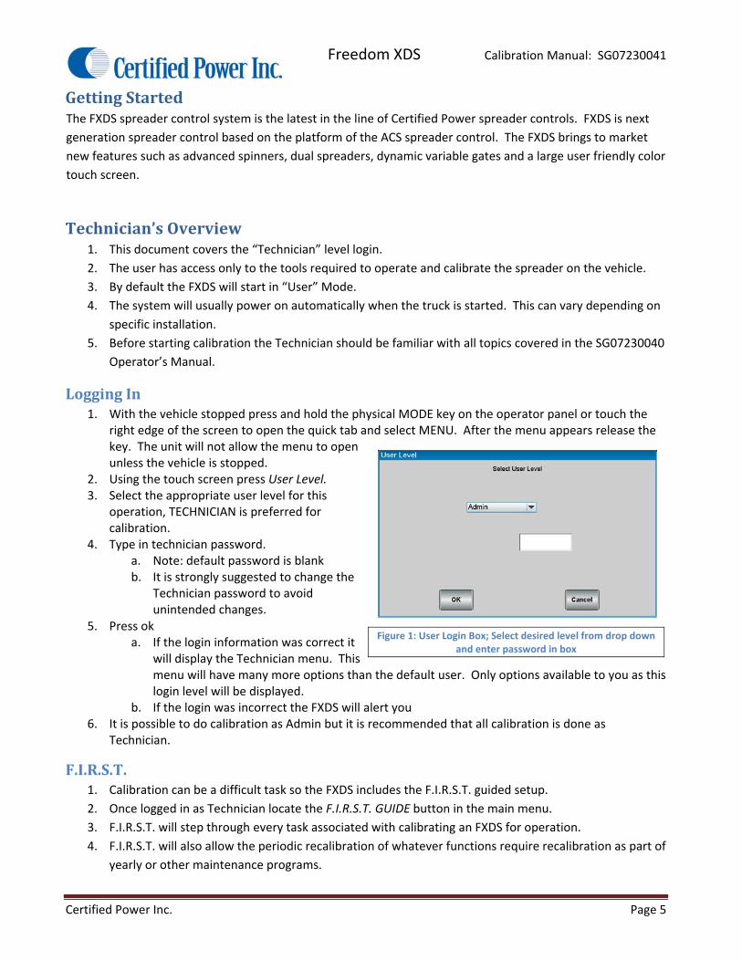
LoggingIn1. With the vehicle stopped press and hold the physical MODE key on the operator panel or touch the
right edge of the screen to open the quick tab and select MENU. After the menu appears release the key. The unit will not allow the menu to open unless the vehicle is stopped.
2. Using the touch screen press User Level. 3. Select the appropriate user level for this
operation, TECHNICIAN is preferred for calibration.
4. Type in technician password. a. Note: default password is blank b. It is strongly suggested to change the
Technician password to avoid unintended changes.
5. Press ok a. If the login information was correct it
will display the Technician menu. This menu will have many more options than the default user. Only options available to you as this login level will be displayed.
b. If the login was incorrect the FXDS will alert you 6. It is possible to do calibration as Admin but it is recommended that all calibration is done as
Technician.
F.I.R.S.T.1. Calibration can be a difficult task so the FXDS includes the F.I.R.S.T. guided setup.
2. Once logged in as Technician locate the F.I.R.S.T. GUIDE button in the main menu.
3. F.I.R.S.T. will step through every task associated with calibrating an FXDS for operation.
4. F.I.R.S.T. will also allow the periodic recalibration of whatever functions require recalibration as part of
yearly or other maintenance programs.
Figure 1: User Login Box; Select desired level from drop down and enter password in box
Freedom XDS Calibration Manual: SG07230041
Certified Power Inc. Page 6
5. View calibration section of this manual for further details on calibration functions.
6. You should be familiar with all topics covered in this manual before attempting to perform a FIRST
setup.
Date/Time1. A new FXDS may not arrive with the correct date and time entered. The unit will warn the operator
that one or both of these values are not correctly set.
2. To check and set the date and time valves enter the Main Menu ‐> System Setup.
a. There are two menus here for setting these valves
b. Date: Sets the current date
c. Time: Sets the current time
3. In either menu set the correct information with the drop down menus and press “Ok”.
4. The new Date and Time are now set and the system will no longer indicate the times are not set.
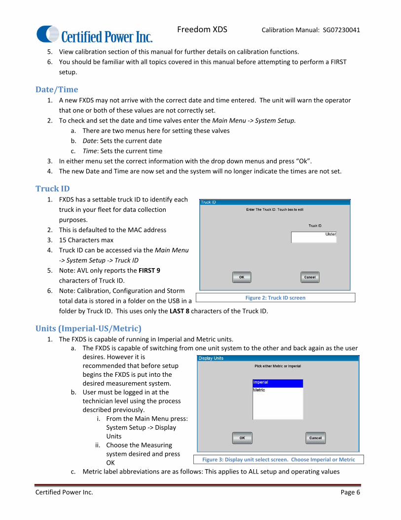
TruckID1. FXDS has a settable truck ID to identify each
truck in your fleet for data collection
purposes.
2. This is defaulted to the MAC address
3. 15 Characters max
4. Truck ID can be accessed via the Main Menu
‐> System Setup ‐> Truck ID
5. Note: AVL only reports the FIRST 9
characters of Truck ID.
6. Note: Calibration, Configuration and Storm
total data is stored in a folder on the USB in a
folder by Truck ID. This uses only the LAST 8 characters of the Truck ID.
Units(Imperial‐US/Metric)1. The FXDS is capable of running in Imperial and Metric units.
a. The FXDS is capable of switching from one unit system to the other and back again as the user desires. However it is recommended that before setup begins the FXDS is put into the desired measurement system.
b. User must be logged in at the technician level using the process described previously.
i. From the Main Menu press: System Setup ‐> Display Units
ii. Choose the Measuring system desired and press OK
c. Metric label abbreviations are as follows: This applies to ALL setup and operating values
Figure 2: Truck ID screen
Figure 3: Display unit select screen. Choose Imperial or Metric
Freedom XDS Calibration Manual: SG07230041
Certified Power Inc. Page 7
i. kg ‐ Kilogram
ii. km – Kilometer
iii. MT – Metric Ton or tonne
iv. kg/Ln.km – Kilogram per Lane Kilometer
v. l/kg ‐ Liters per Kilogram
vi. l/min. – Liters per Minute
vii. km/h ‐ Kilometers per Hour
viii. kg/min. – Kilograms per Minute
2. To change this setting navigate to Main Menu ‐> System Setup ‐> Display Units
Calibration1. This section will guide you through the calibration necessary for operation of the FXDS.
2. Log In as Technician for calibration.
EquipmentNeeded1. Fully functioning Truck with Spreader installed. 2. Materials intended for use. i.e., salt, sand, or cinders. 3. Pre‐Wet with sufficient fluid in the tanks.
a. Use caution if using straight water. Water will freeze, causing major damage to all system components.
b. If water is to be used for calibration, be sure to flush the system thoroughly with windshield washer fluid when calibration is completed to prevent freezing.
4. Available Truck scale for measuring the weight of the vehicle before and after a measured dump. 5. A calculator (if setting up multiple materials). 6. A bathroom scale and 5 gallon bucket and shovel (if truck scale is unavailable).
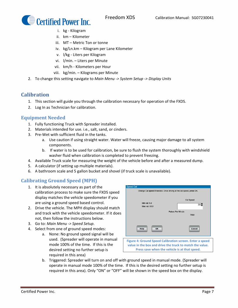
CalibratingGroundSpeed(MPH)1. It is absolutely necessary as part of the
calibration process to make sure the FXDS speed display matches the vehicle speedometer if you are using a ground speed based control.
2. Drive the vehicle. The MPH display should match and track with the vehicle speedometer. If it does not, then follow the instructions below.
3. Go to: Main Menu ‐> Speed Setup. 4. Select from one of ground speed modes:
a. None: No ground speed signal will be used. (Spreader will operate in manual mode 100% of the time. If this is the desired setting no further setup is required in this area)
b. Triggered: Spreader will turn on and off with ground speed in manual mode. (Spreader will operate in manual mode 100% of the time. If this is the desired setting no further setup is required in this area). Only “ON” or “OFF” will be shown in the speed box on the display.
Figure 4: Ground Speed Calibration screen. Enter a speed value in the box and drive the truck to match the value.
Press save when the vehicle is at that speed.

Freedom XDS Calibration Manual: SG07230041
Certified Power Inc. Page 8
c. Oriented: Spreader will be able to run in full automatic mode. Spreader will automatically adjust output rate to match ground speed.
5. Vehicle Speed input type a. VRM: This setting used for Low voltage AC signals. This type of input can be susceptible to
noise and the wiring should be shielded with the shield connected to chassis ground. b. Mechanical Source: This is the most typical setting. This setting will be used in most
applications where the MPH signal source is the vehicles computer. Always check with the vehicle manufacturer before attaching to any vehicle wiring.
c. Mechanical Sink: Typically this setting is used for after‐market hall‐sensors that are NPN open‐collector output.
d. Low Voltage: Same as mechanical source. 6. Confirm your selection and then enter the Speed Cal menu. You will now calibrate the FXDS’s speed
input. 7. Change the “Cal Speed” value to the vehicle speed you intend to drive at. Typical values are around
30 mph. 8. Caution! Have someone else drive the vehicle while ANY calibration adjustments are made. 9. While the vehicle is in motion and the dash speedometer reads exactly the value you set in “Speed
Cal” press OK to save the value a. If no pulses appear on screen the ground speed is incorrectly wired or configured. Check your
ground speed type and wiring and attempt to calibrate ground speed again. b. When you return to the main operation screen the speed shown on the FXDS should now
match the vehicle speedometer. 10. OPTIONAL: Enter the Speed Setup ‐> Speed Threshold menu. This variable changes the size of a speed
change required for the FXDS to react. 0.5 is the recommended setting.
ConfiguringtheFeeder1. The following section covers the setup of the trucks auger or conveyors
2. This includes cross augers
a. Cross augers do not have materials that need to be setup
b. Cross augers do not need to have measured dump run
c. The only setup required on the cross auger is to set the trims
3. IF YOU ARE USING GATE CONTROL CONFIGURE GATE CONTROL BEFORE CONFIGURING THE FEEDER
ConfiguringMaterials1. Before calibrating the feeder it is necessary to define the materials you intend to spread.
2. To setup materials navigate to the Material Setup screen. It is found Main Menu ‐> Configuration ‐>
Feeder Setup OR Liquid Setup ‐> Name of Spreader ‐> Material Setup
3. There are (10) materials allowed in the FXDS. Each have the following attributes:
a. Material Name: A unique name that identifies the material such as “SALT” or
“50SALT50SAND” for a 50% salt sand mixture.
b. Speed Required: Sets if there is a requirement for ground speed to “Blast” material. If set to
“NO” the vehicle can Blast while not moving
Freedom XDS Calibration Manual: SG07230041
Certified Power Inc. Page 9
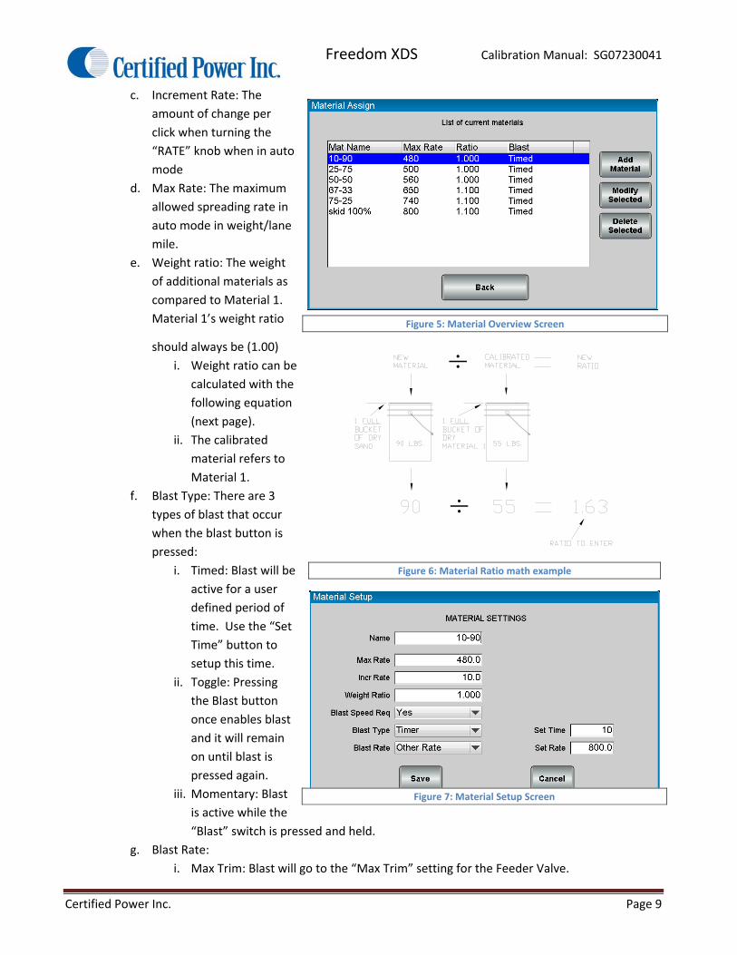
c. Increment Rate: The
amount of change per
click when turning the
“RATE” knob when in auto
mode
d. Max Rate: The maximum
allowed spreading rate in
auto mode in weight/lane
mile.
e. Weight ratio: The weight
of additional materials as
compared to Material 1.
Material 1’s weight ratio
should always be (1.00)
i. Weight ratio can be
calculated with the
following equation
(next page).
ii. The calibrated
material refers to
Material 1.
f. Blast Type: There are 3
types of blast that occur
when the blast button is
pressed:
i. Timed: Blast will be
active for a user
defined period of
time. Use the “Set
Time” button to
setup this time.
ii. Toggle: Pressing
the Blast button
once enables blast
and it will remain
on until blast is
pressed again.
iii. Momentary: Blast
is active while the
“Blast” switch is pressed and held.
g. Blast Rate:
i. Max Trim: Blast will go to the “Max Trim” setting for the Feeder Valve.
÷
÷Figure 5: Material Overview Screen
Figure 6: Material Ratio math example
Figure 7: Material Setup Screen
Freedom XDS Calibration Manual: SG07230041
Certified Power Inc. Page 10
ii. Max Rate: Blast will go to the “Maximum Rate” setting for this material. (You set this at
the beginning of Materials section.)
iii. Other Rate: Use alternative rate chosen. Note this rate is limited by the Max Trim
setting.
SettingTrims1. Set/Check Trims (Rough Adjustments)
a. Before loading the vehicle: It’s good to set rough trims. This eliminates excess material being
spread during the measured dump process.
b. Max Trim: Navigate to the Trims Cal menu. Adjust maximum trim and SAVE the new max
value.
i. Setting should be the highest pulse count achieved. Do not raise trim beyond the max
pulse count
ii. If there is no closed loop feedback determine when the function no longer runs any
faster even with increased trim. A photo tachometer is helpful for this process.
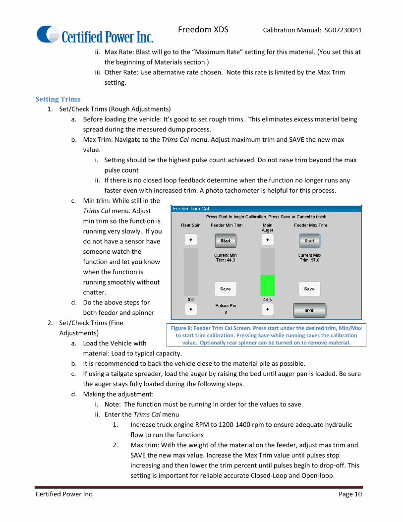
c. Min trim: While still in the
Trims Cal menu. Adjust
min trim so the function is
running very slowly. If you
do not have a sensor have
someone watch the
function and let you know
when the function is
running smoothly without
chatter.
d. Do the above steps for
both feeder and spinner
2. Set/Check Trims (Fine
Adjustments)
a. Load the Vehicle with
material: Load to typical capacity.
b. It is recommended to back the vehicle close to the material pile as possible.
c. If using a tailgate spreader, load the auger by raising the bed until auger pan is loaded. Be sure
the auger stays fully loaded during the following steps.
d. Making the adjustment:
i. Note: The function must be running in order for the values to save.
ii. Enter the Trims Cal menu
1. Increase truck engine RPM to 1200‐1400 rpm to ensure adequate hydraulic
flow to run the functions
2. Max trim: With the weight of the material on the feeder, adjust max trim and
SAVE the new max value. Increase the Max Trim value until pulses stop
increasing and then lower the trim percent until pulses begin to drop‐off. This
setting is important for reliable accurate Closed‐Loop and Open‐loop.
Figure 8: Feeder Trim Cal Screen. Press start under the desired trim, Min/Max to start trim calibration. Pressing Save while running saves the calibration
value. Optionally rear spinner can be turned on to remove material.
Freedom XDS Calibration Manual: SG07230041
Certified Power Inc. Page 11
3. If running open loop, it is best to use a hand held tachometer somewhere on
the feeder mechanism. Have an assistant use the tachometer and call out the
RPM until an increase in the MAX TRIM value no longer increases feeder RPM.
iii. While still in the Trims Cal menu
1. Min trim: With the weight of the material on the feeder, press START. Adjust
min trim so the spreader moves consistently without chatter.
2. If running open loop (no sensor), adjust min trim to point where feeder is
running as slow as possible but without stalling.
ClosedLoopMeasuredDump1. Note: The procedure below is for use when gate mode is disabled on the truck. For measured dump
calibration with a gate see the “Gate Setup” section of this manual.
2. Starting Closed Loop Measured Dump.
a. You may make changes to vary the output from 1‐100% at any time.
b. Increase truck engine RPM to 1200‐1400 rpm to ensure adequate hydraulic flow to run the
functions.
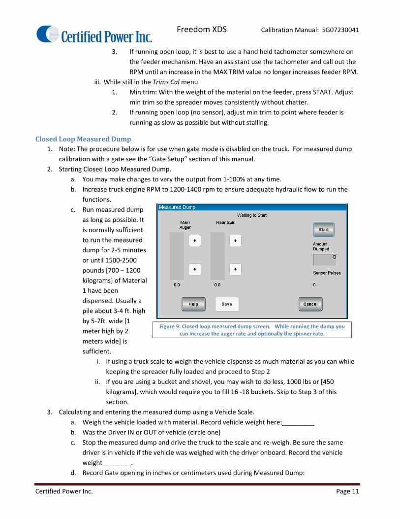
c. Run measured dump
as long as possible. It
is normally sufficient
to run the measured
dump for 2‐5 minutes
or until 1500‐2500
pounds [700 – 1200
kilograms] of Material
1 have been
dispensed. Usually a
pile about 3‐4 ft. high
by 5‐7ft. wide [1
meter high by 2
meters wide] is
sufficient.
i. If using a truck scale to weigh the vehicle dispense as much material as you can while
keeping the spreader fully loaded and proceed to Step 2
ii. If you are using a bucket and shovel, you may wish to do less, 1000 lbs or [450
kilograms], which would require you to fill 16 ‐18 buckets. Skip to Step 3 of this
section.
3. Calculating and entering the measured dump using a Vehicle Scale.
a. Weigh the vehicle loaded with material. Record vehicle weight here:_________
b. Was the Driver IN or OUT of vehicle (circle one)
c. Stop the measured dump and drive the truck to the scale and re‐weigh. Be sure the same
driver is in vehicle if the vehicle was weighed with the driver onboard. Record the vehicle
weight________.
d. Record Gate opening in inches or centimeters used during Measured Dump:
Figure 9: Closed loop measured dump screen. While running the dump you can increase the auger rate and optionally the spinner rate.

Freedom XDS Calibration Manual: SG07230041
Certified Power Inc. Page 12
________inches or _______centimeters
e. Press the “Start” key to begin the dump. Pressing “Stop” will pause the measured dump at any
time. Simply press start again to continue dumping material.
f. Original weight of truck (recorded above)_______(‐) new weight of truck (after dump)______
= total weight of material dispensed ________(lbs. or Kg. dumped).
g. Key in the weight of the material for “Pounds Dumped” or “Kilograms Dumped” in the space
provided on the screen. Before saving this number double check that the information input is
accurate. If this number is not accurate the spreader will not be accurate and may not
operate correctly.
h. Press save
4. Alternative weighing method using the bathroom scale, bucket, and shovel Method:
a. Create a pile roughly 3ft. high by 5‐6 ft wide. [1 meter high by 2 meters wide].
b. Weigh the empty bucket. Record the weight in the blank space provided below for “empty
bucket weight.”
c. Shovel the material into a 5 gallon bucket.
d. Weigh the first FULL bucket. Record it below.
e. Subtract the weight of the empty bucket from the full bucket weight completing the equation
below. The result is the material weight of one bucket. Record the weight below.
f. Full bucket weight_______ (‐) empty bucket weight ______ = Material weight per bucket
________ (lbs. or Kg)
g. Fill the bucket with Material 1 as before and count the total number of buckets filled. Record
this information so you do not lose track of how many buckets you’ve filled. Also, do not
forget to count the first bucket.
h. If you have a partial bucket at the end, weigh this bucket on the scale and subtract the empty
bucket weight.
i. Use this equation to calculate the total Material 1 dumped:
Total number of buckets________ (x) material weight______ = total material weight_______
j. Enter this number in the space provided on the screen. Before saving this number double
check that the information entered is accurate. If this number is not accurate the spreader
will not be accurate and may not operate correctly.
k. Press Save
5. Manually enter Pounds/Pulse [Kilograms/Pulse]
a. It’s not necessary to run measured dump if the Pounds/Pulse [Kilograms/Pulse] value is
known. It can be manually entered at any time. This could be necessary for any reason if
calibration variables may have been lost because the controller has been replaced or the unit
has had factory defaults restored by the administrator.
b. These values can also be saved via the Save and Restore menu under calibration. It is highly
recommended that calibrations for each truck be saved incase a problem occurs with the
spreader unit. Please read the section on Saving and Restoring for more information on this
topic.
OpenLoopMeasuredDump1. Starting Open Loop Measured Dump
Freedom XDS Calibration Manual: SG07230041
Certified Power Inc. Page 13
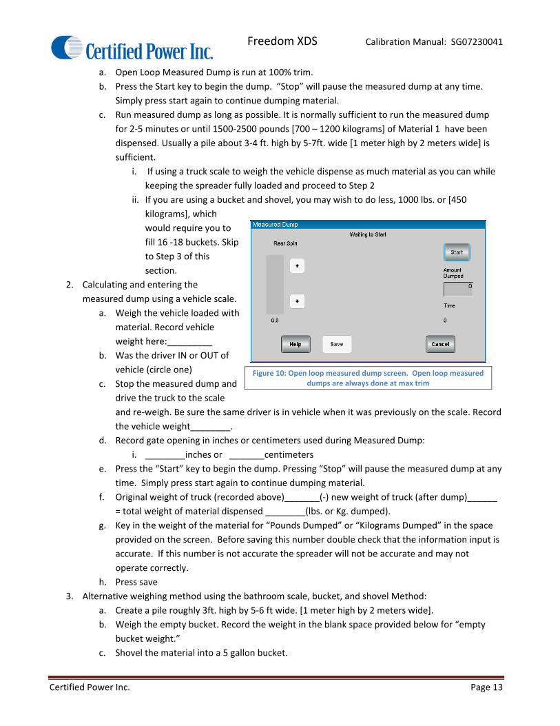
a. Open Loop Measured Dump is run at 100% trim.
b. Press the Start key to begin the dump. “Stop” will pause the measured dump at any time.
Simply press start again to continue dumping material.
c. Run measured dump as long as possible. It is normally sufficient to run the measured dump
for 2‐5 minutes or until 1500‐2500 pounds [700 – 1200 kilograms] of Material 1 have been
dispensed. Usually a pile about 3‐4 ft. high by 5‐7ft. wide [1 meter high by 2 meters wide] is
sufficient.
i. If using a truck scale to weigh the vehicle dispense as much material as you can while
keeping the spreader fully loaded and proceed to Step 2
ii. If you are using a bucket and shovel, you may wish to do less, 1000 lbs. or [450
kilograms], which
would require you to
fill 16 ‐18 buckets. Skip
to Step 3 of this
section.
2. Calculating and entering the
measured dump using a vehicle scale.
a. Weigh the vehicle loaded with
material. Record vehicle
weight here:_________
b. Was the driver IN or OUT of
vehicle (circle one)
c. Stop the measured dump and
drive the truck to the scale
and re‐weigh. Be sure the same driver is in vehicle when it was previously on the scale. Record
the vehicle weight________.
d. Record gate opening in inches or centimeters used during Measured Dump:
i. ________inches or _______centimeters
e. Press the “Start” key to begin the dump. Pressing “Stop” will pause the measured dump at any
time. Simply press start again to continue dumping material.
f. Original weight of truck (recorded above)_______(‐) new weight of truck (after dump)______
= total weight of material dispensed ________(lbs. or Kg. dumped).
g. Key in the weight of the material for “Pounds Dumped” or “Kilograms Dumped” in the space
provided on the screen. Before saving this number double check that the information input is
accurate. If this number is not accurate the spreader will not be accurate and may not
operate correctly.
h. Press save
3. Alternative weighing method using the bathroom scale, bucket, and shovel Method:
a. Create a pile roughly 3ft. high by 5‐6 ft wide. [1 meter high by 2 meters wide].
b. Weigh the empty bucket. Record the weight in the blank space provided below for “empty
bucket weight.”
c. Shovel the material into a 5 gallon bucket.
Figure 10: Open loop measured dump screen. Open loop measured dumps are always done at max trim

Freedom XDS Calibration Manual: SG07230041
Certified Power Inc. Page 14
d. Weigh the first FULL bucket. Record it below.
e. Subtract the weight of the empty bucket from the full bucket weight completing the equation
below. The result is the material weight of one bucket. Record the weight below.
f. Full bucket weight_______ (‐) empty bucket weight ______ = Material weight per bucket
________ (lbs. or Kg)
g. Fill the bucket with Material 1 as before and count the total number of buckets filled. Record
this information so you do not lose track of how many buckets you’ve filled. Also, do not
forget to count the first bucket.
h. If you have a partial bucket at the end, weigh this bucket on the scale and subtract the empty
bucket weight.
i. Use this equation to calculate the total Material 1 dumped:
i. Total number of buckets________ (x) material weight______ = total material
weight_______
j. Enter this number in the space provided on the screen. Before saving this number double
check that the information entered is accurate. If this number is not accurate the spreader
will not be accurate and may not operate correctly.
k. Press Save
4. Manually enter Pounds/Pulse [Kilograms/Pulse]
a. It’s not necessary to run measured dump if the Pounds/Pulse [Kilograms/Pulse] value is
known. It can be manually entered at any time. This could be necessary for any reason if
calibration variables may have been lost because the controller has been replaced or the unit
has had factory defaults restored by the administrator.
b. These values can also be saved via the Save and Restore menu under calibration. It is highly
recommended that calibrations for each truck be saved incase a problem occurs with the
spreader unit. Please read the section on “Saving and Restoring” for more information on this
topic.
GateCalibration1. Gate calibration takes place in two steps
2. Calibration of the Gate
3. Calibration of the Spreader
4. If gate of any type is enabled gate should be setup prior to the calibration of the feeder.
ManualGate1. Manual gate is simply a gate on the back of the truck that has no pneumatic or hydraulic actuator
attached to it.
2. Manual gate may have an electronic position sensor attached to the gate to read position.
3. To calibrate the gate first set the following items
a. Minimum gate heights the operator is allowed to enter. Accessed via Configuration ‐>Spinner
Setup ‐>GATE NAME ‐> Gate Min Height
b. Maximum gate heights the operator is allowed to enter. Accessed via Configuration ‐>Spinner
Setup ‐>GATE NAME ‐> Gate Max Height
Freedom XDS Calibration Manual: SG07230041
Certified Power Inc. Page 15
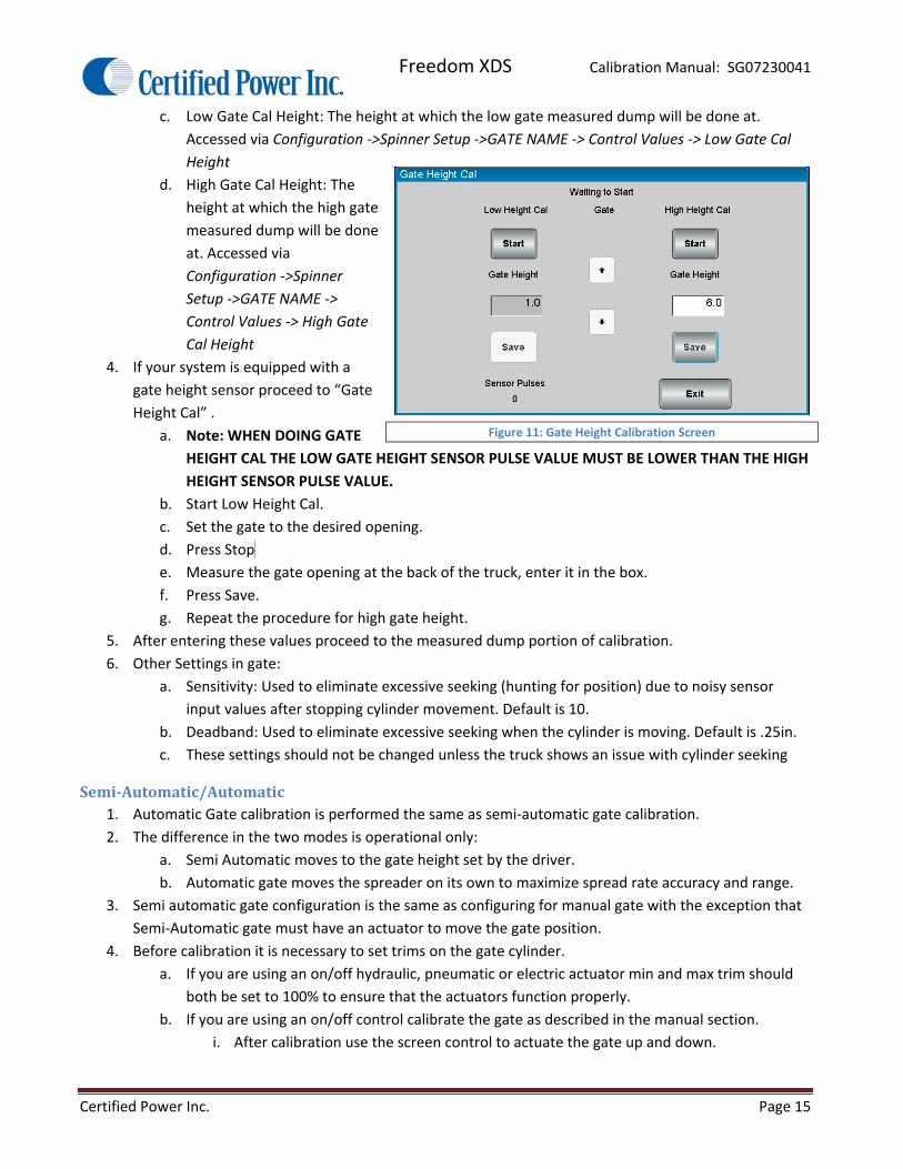
c. Low Gate Cal Height: The height at which the low gate measured dump will be done at.
Accessed via Configuration ‐>Spinner Setup ‐>GATE NAME ‐> Control Values ‐> Low Gate Cal
Height
d. High Gate Cal Height: The
height at which the high gate
measured dump will be done
at. Accessed via
Configuration ‐>Spinner
Setup ‐>GATE NAME ‐>
Control Values ‐> High Gate
Cal Height
4. If your system is equipped with a
gate height sensor proceed to “Gate
Height Cal” .
a. Note: WHEN DOING GATE
HEIGHT CAL THE LOW GATE HEIGHT SENSOR PULSE VALUE MUST BE LOWER THAN THE HIGH
HEIGHT SENSOR PULSE VALUE.
b. Start Low Height Cal.
c. Set the gate to the desired opening.
d. Press Stop .
e. Measure the gate opening at the back of the truck, enter it in the box.
f. Press Save.
g. Repeat the procedure for high gate height.
5. After entering these values proceed to the measured dump portion of calibration.
6. Other Settings in gate:
a. Sensitivity: Used to eliminate excessive seeking (hunting for position) due to noisy sensor
input values after stopping cylinder movement. Default is 10.
b. Deadband: Used to eliminate excessive seeking when the cylinder is moving. Default is .25in.
c. These settings should not be changed unless the truck shows an issue with cylinder seeking
Semi‐Automatic/Automatic1. Automatic Gate calibration is performed the same as semi‐automatic gate calibration.
2. The difference in the two modes is operational only:
a. Semi Automatic moves to the gate height set by the driver.
b. Automatic gate moves the spreader on its own to maximize spread rate accuracy and range.
3. Semi automatic gate configuration is the same as configuring for manual gate with the exception that
Semi‐Automatic gate must have an actuator to move the gate position.
4. Before calibration it is necessary to set trims on the gate cylinder.
a. If you are using an on/off hydraulic, pneumatic or electric actuator min and max trim should
both be set to 100% to ensure that the actuators function properly.
b. If you are using an on/off control calibrate the gate as described in the manual section.
i. After calibration use the screen control to actuate the gate up and down.
Figure 11: Gate Height Calibration Screen
Freedom XDS Calibration Manual: SG07230041
Certified Power Inc. Page 16
ii. If the gate is moving too slow/too fast use the flow control provided with the valve to
adjust the speed of the gate. The gate should take 4‐5 seconds to move the span from
min opening to max opening.
b. If you are using a hydraulic cylinder with a proportional valve you can set valve trims to
moderate the speed.
2. Setting trims
a. This process should only be followed if the gate is being controlled by a proportional hydraulic
actuator.
b. If using an electric actuator set min trim to 97 and max trim to 98.
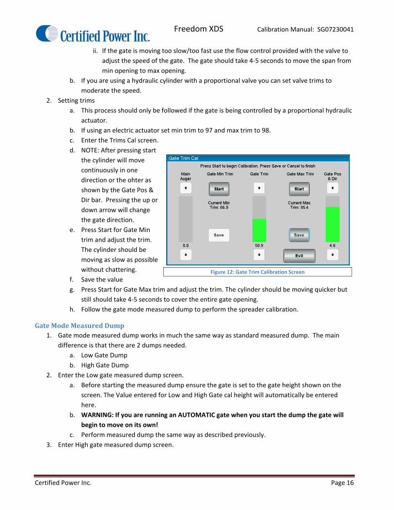
c. Enter the Trims Cal screen.
d. NOTE: After pressing start
the cylinder will move
continuously in one
direction or the ohter as
shown by the Gate Pos &
Dir bar. Pressing the up or
down arrow will change
the gate direction.
e. Press Start for Gate Min
trim and adjust the trim.
The cylinder should be
moving as slow as possible
without chattering.
f. Save the value
g. Press Start for Gate Max trim and adjust the trim. The cylinder should be moving quicker but
still should take 4‐5 seconds to cover the entire gate opening.
h. Follow the gate mode measured dump to perform the spreader calibration.
GateModeMeasuredDump1. Gate mode measured dump works in much the same way as standard measured dump. The main
difference is that there are 2 dumps needed.
a. Low Gate Dump
b. High Gate Dump
2. Enter the Low gate measured dump screen.
a. Before starting the measured dump ensure the gate is set to the gate height shown on the
screen. The Value entered for Low and High Gate cal height will automatically be entered
here.
b. WARNING: If you are running an AUTOMATIC gate when you start the dump the gate will
begin to move on its own!
c. Perform measured dump the same way as described previously.
3. Enter High gate measured dump screen.
Figure 12: Gate Trim Calibration Screen

Freedom XDS Calibration Manual: SG07230041
Certified Power Inc. Page 17
a. Before starting the measured dump ensure the gate is set to the gate height shown on the
screen. The Value entered for Low and High Gate cal height will automatically be entered
here.
b. WARNING: If you are running an AUTOMATIC gate when you start the dump the gate will
begin to move on its own!
c. Perform measured dump the same way as described previously.
4. The gate/feeder calibration is now complete.
SpinnerCalibration
SettingMin/MaxTrims1. Spinner Min/Max trims must be set prior to specific settings for the spinner type. Set trim first.
2. Navigate to Configuration ‐>Spinner Setup ‐>SPINNER NAME ‐> Trims Cal.
3. For ZV spinners see the notes in the ZV spinner section about min/max trims
4. Feeder is also available so material
spread distance can be judged.
a. Closed Loop
i. Trims Cal: (Max Trim)
Adjust min trim for
the lowest pulses
possible pulses. Press
“Save” to save the
calibration
ii. Trims Cal: (Min Trim)
Adjust Max Trim for
the highest pulse
count (sensor feedback) without raising the Max trim value above where pulses stop
increasing. Raising this too high will cause poor resolution on the liquid control
iii. If a feedback sensor pulse signal is unavailable the trims will not save in closed loop
mode.
b. Open Loop
i. Trims Cal: (Mix Trim) Adjust min trim so the spinner moves at the lowest speed without
pulsating. Press “Save” to save the calibration
ii. Trims Cal: (Max Trim) Adjust Max Trim to the highest speed the spinner can run.
NOTE: this is not 100%, it is the point where the spinner will not spin any faster.
PercentMode1. Percent mode spinner is utilized when the operator needs complete control over the Spinner speed.
Percent mode spinner has no interaction with the Feeder. See Lane Control Spinner below if you wish
to have the feeder controlled by number of Spinner lanes active (Lane control).
2. There’s no calibration necessary for percent mode spinner. It is only necessary to make sure trim
levels are set properly under load.
3. Load the truck with material if it’s not already loaded from performing a measured dump.
Figure 13: Spinner Trim calibration screen

Freedom XDS Calibration Manual: SG07230041
Certified Power Inc. Page 18
4. Navigate to Calibration menu via Configuration ‐> Spinner Setup ‐> SPINNER NAME ‐> Valve Setup.
5. If Spinner is setup for percent mode the menu sequence is as follows.
6. CAUTION! Spinner is live when you going into MIN or MAX trim! Be sure all personnel are well clear
of the vehicle!
7. Closed Loop spinner works identical to open loop spinner; the only difference will be pulses/min will
be shown on the calibration screen with the presence of a working spinner sensor circuit.
LaneMode1. Lane control is used when it’s important to keep uniform lbs/lane mile (lbs/Ln.mi.) [kg/Ln.km metric
mode] across all lanes while the truck is dispensing material.
a. The feeder speed is tied to the spinner speed
b. As the spinner is changed from 1 to 2 lanes, the feeder output is automatically doubled. If 3
lanes are selected the feed rate is tripled.
2. This calibration is identical regardless of spinner feedback (open/closed loop)
3. Perform Trim adjustments as detailed in the previous section for Percent Mode Spinner
4. Ensure you are in “Lane” mode by checking the Spinner Mode menu under the Spinner Setup menu.
5. Set the number of lanes by entering the
Configuration ‐> Spinner Setup ‐>
SPINNER NAME ‐> Control Values ‐> Max
Lanes.
a. NUMBER OF LANES should be
chosen with the following
conditions applied:
i. In LANE MODE; The
Spinner controls the
Feeder. Setting “Number
of Lanes” to (4) allows the
driver of the vehicle to
select 1 to 4 lanes. The Feeder and Pre‐Wet must be capable of putting out 4X the
displayed feed rate set on the operating screen.
ii. If the feeder cannot keep up with the requirement, the operator will get “FEED RATE
LIMITED” error in operating mode, and will see similar errors for the Pre‐Wet as well.
b. CAUTION! Keep all personnel clear of the mechanism. The Feeder and Spinner are active
when adjusting “Spinner Cal”. The Feeder will activate by turning the feeder knob clockwise.
0‐100% of valve trim is available while adjusting the Lane % calibration value. You may also
use the buttons available on screen.
6. Adjust Lane % Calibration up/down with the display arrow keys for one (1) lane of coverage. It may be
necessary to drive the vehicle so you may account for material scatter. USE CAUTION! Be sure feeder
is loading the Spinner with material (salt) while calibrating lanes.
a. If running (2) lanes you must keep “Lane % Calibration” below 50.
b. If running (3) lanes you must keep “Lane % Calibration” below 33.
c. If running (4) lanes you must keep “Lane % Calibration” below 25.
Figure 14: Spinner mode configuration screen
Freedom XDS Calibration Manual: SG07230041
Certified Power Inc. Page 19
ZeroVelocitySpinners(ZV)1. This section describes the calibration of a ZV spinner. If your truck is not equipped with a ZV spinner
you can skip this section.
a. Material being distributed to the road surface is accelerated at a speed equal to the current
vehicle speed in Miles Per hour or [Kilometer per hour metric mode] but in the opposite
direction to which the vehicle is traveling therefore canceling material velocity in relation to
the road surface.
b. As material contacts the road surface it will not tumble and scatter. It becomes possible to
place material in an exact location such as on the crown of the road. This reduces the amount
of wasted material that tumbles to areas of little usefulness.
2. Prep and setup of a ZV Spinner
a. The speed must first be calibrated before calibration of the ZV spinner. Ensure the speed is
properly calibrated by driving the truck and comparing the screen readout to the truck
speedometer.
b. If the speed is ever recalibrated the ZV spinner must then also be recalibrated.
c. ZV spinner must first be selected by the Administrator before proceeding.
d. If ZV is not enabled and a ZV spinner is present on the truck contact your fleet administrator
to enable the feature.
e. The hydraulic system should be brought up to normal operating temperature. This is
especially important if performing an Open‐loop calibration!
f. The vehicle should be loaded with material most typically spread by the ZV spreader.
g. If running variable gate, have the gate adjusted to the most typical opening. Be sure
the current height is displaying on the operating screen.
h. All motor sensors should be wired and functional for closed‐loop operation.
i. Adjust the ZV chute for typical angle and elevation.
3. Trim Adjustment
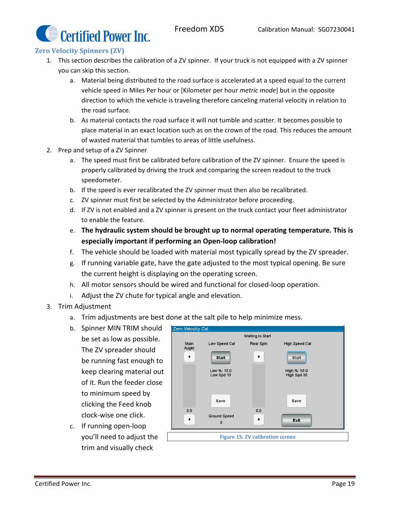
a. Trim adjustments are best done at the salt pile to help minimize mess.
b. Spinner MIN TRIM should
be set as low as possible.
The ZV spreader should
be running fast enough to
keep clearing material out
of it. Run the feeder close
to minimum speed by
clicking the Feed knob
clock‐wise one click.
c. If running open‐loop
you’ll need to adjust the
trim and visually check
Figure 15: ZV calibration screen
Freedom XDS Calibration Manual: SG07230041
Certified Power Inc. Page 20
operation at the back of the truck. If someone can help you it makes the process work
more efficiently.
d. MAX TRIM should be adjusted with NO granular material running through the ZV
mechanism. This is because we wish to find the absolute maximum velocity the ZV can
run under NO load or minimum load; however be sure NOT to exceed the mechanical
limits established by the ZV manufacturer.
4. Getting ready for calibration
a. During the calibration we will set two calibration points
i. Low Speed Cal
ii. High Speed Cal
b. The rest of the calibration involves driving the truck.
c. Find a low to no traffic area for testing if possible.
d. The ZV spinner will activate with the next step.
e. Open‐loop ZV calibration is performed the same as closed‐loop so both are covered
here under the same text. The only difference is the “Open‐loop Cal factor” is
generated internally based on valve trim percent. Changing the “Open‐Loop Factor” or
“Vehicle Speed” value have the same effect on Open‐loop control as “Pulses/Minute”
and “Vehicle Speed” do to Closed‐loop control as described previously for “Manual Cal
value Adjustment”.
f. If calibrating a closed‐loop system, open‐loop values are automatically saved
simultaneously while saving closed loop values. Open‐loop values are necessary in
event sensor failure occurs white operating closed‐loop mode. The number value
stored for open‐loop operation “Open loop Factor” is identical to the “Pulses/Minute”
value for closed‐loop systems.
5. Low Speed Calibration
a. Typical low speed calibration would be in the 5‐8MPH range.
b. Press the “Start” key on the low speed Cal side of the screen.
c. Set the spinner rate using the “Rear Spin” bar in the center of the screen.
d. Slightly increase the feeder rate to send material to the ZV spinner.
e. Drive the vehicle and locate a speed where material ZV is reached.
i. It is useful to have a spotter in another vehicle tell you when the rates match.
ii. When the speeds match press “Save” to store the values.
6. High Speed Calibration
a. Repeat the same procedure for High Speed calibration.
b. The High speed value should be calibrated to the most common vehicle speed
traveled. e.g. 30‐35 MPH.
c. Increase feeder output setting the feed rate to 50‐75% of maximum.
7. ZV Cal values can be adjusted manually if needed after the ZV has been tested in operating
mode. This is especially true for Open‐loop control.
Freedom XDS Calibration Manual: SG07230041
Certified Power Inc. Page 21
a. It is recommended that if calibrating closed‐loop that open‐loop control be tested by
disconnecting the spinner sensor. This places the control in open loop mode.
b. Adjust cal values if necessary. Adjusting cal values while running open‐loop will only
improve the responsiveness of closed‐loop as well.
8. Note: If PPM (pulses/minute) stops increasing with increases to the “Valve Drive Adjust”
value, then you have already reached maximum hydraulic flow and ZV velocity and you need
to decrease valve drive until the PPM drops off slightly. This also sets the maximum speed at
which you will be able to operate the ZV spreader. In event max speed is exceeded while in
normal ‘Operating Mode’ the driver will receive an error message on the screen.
9. Operator (override) LANE knob adjustment range
a. The following set the operator override adjustments for ZV spinner
b. In the “Control Values” Section there are two settings
i. Zero Velocity Max Offset
1. Sets the maximum adjustment +/‐ to give additional control to the
operator
2. This value works on either side of zero; +/‐ 10 PMH to better control
pattern.
3. 10 MPH is the default
ii. Zero Velocity Increment
1. Sets the MPH increment from one click up or down of the spinner knob.
2. The default setting is 1 MPH
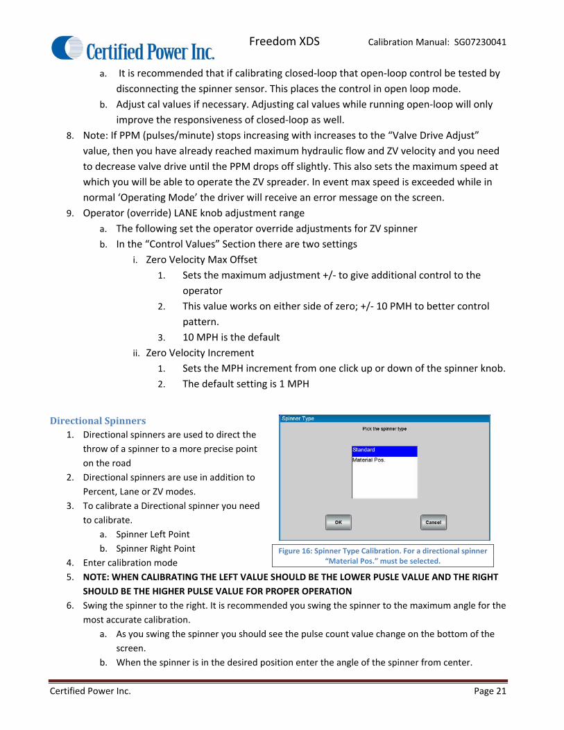
DirectionalSpinners1. Directional spinners are used to direct the
throw of a spinner to a more precise point
on the road
2. Directional spinners are use in addition to
Percent, Lane or ZV modes.
3. To calibrate a Directional spinner you need
to calibrate.
a. Spinner Left Point
b. Spinner Right Point
4. Enter calibration mode
5. NOTE: WHEN CALIBRATING THE LEFT VALUE SHOULD BE THE LOWER PUSLE VALUE AND THE RIGHT
SHOULD BE THE HIGHER PULSE VALUE FOR PROPER OPERATION
6. Swing the spinner to the right. It is recommended you swing the spinner to the maximum angle for the
most accurate calibration.
a. As you swing the spinner you should see the pulse count value change on the bottom of the
screen.
b. When the spinner is in the desired position enter the angle of the spinner from center.
Figure 16: Spinner Type Calibration. For a directional spinner “Material Pos.” must be selected.

Freedom XDS Calibration Manual: SG07230041
Certified Power Inc. Page 22
c. Press save
7. Swing the spreader to the left. It is
recommended you swing the spinner to the
maximum angle for the most accurate
calibration.
a. As you swing the spinner you should
see the pulse count value change on
the bottom of the screen.
b. When the spinner is in the desired
position enter the angle of the
spinner from center.
c. Press save
8. Your spinner bar should now show the current direction of the spinner by angling the bar to the left
and to right as the spinner moves.
SwensonPPSG2DirectionalSpinner1. The Swenson PPS G2 spinner allows the
driver of the truck to place the salt on the
road in various pre determined positions
or any position via manual mode.
2. This spinner type is used in addition to
Percent or Lane modes.
3. To calibrate the spinner first you must
calibrate the spinner actuators fully
extended and fully retracted using the
“Actuator Cal” screen.
4. Press “START” for “Min Actuator Cal” and
fully retract the actuators using the
buttons in the middle of the screen. When
it is fully retracted press save.
5. Press “START” for “Max Actuator Cal” and
fully extend the actuators using the
buttons in the middle of the screen. When
it is fully extended press save.
6. If your feedback reads 0 when you try to
calibrate jog the unit back in the opposite
direction so the feedback is just above 0.
This will prevent controller errors.
7. After calibrating the position sensors
calibrate the preset positions:
a. Left
b. Center
c. Right
Figure 17: Directional Spinner Calibration
Figure 18: Swenson PPS Actuator Cal Screen
Figure 19: Swenson PPS Pre programmed position calibration screen

Freedom XDS Calibration Manual: SG07230041
Certified Power Inc. Page 23
d. Left‐Center
e. All
f. Right‐Center
8. Press the arrows to position the chute to the desired spread point.
9. Press the position you’d like to associate with that spread position.
10. Repeat step 8 & 9 for each of the (6) pre calibrated spread points.
PrewetCalibration5. Checklist: Before starting calibration.
a. Fill tanks with liquid.
i. Caution: Water will
freeze causing major
damage to all system
components.
ii. If water is to be used for
calibration, be sure to
flush system thoroughly
with windshield washer
fluid when calibration is
completed to remove all
water.
b. All typical plumbing and nozzles must be attached. Be sure nozzles are clean.
c. Liquid Pump Bypass valve (inside
pump enclosure) must be set
prior to calibration. Contact your
local Certified Power sales
representative if you have
questions about proper valve
settings.
d. Move the vehicle to a location
where it’s ok to dispense liquid
materials.
e. Electric pump motors can be
driven directly by the FXDS.
Valve Frequency is automatically set to 300Hz and current will be internally limited to 6 amps.
Amp loads higher than 6A require a Solid State Relay (SSR) and additional wiring.
f. Ensure the liquid type is set to one of the following in the Liquid Type menu
i. Prewet – use with a hydraulic driven Prewet Pump.
ii. Elec. Prewet – use when directly controlling an electrically driven Prewet Pump.
iii. Prewet On/Off – used for Hydraulic ratio Pre‐wet systems, single speed electric motors,
or relays.
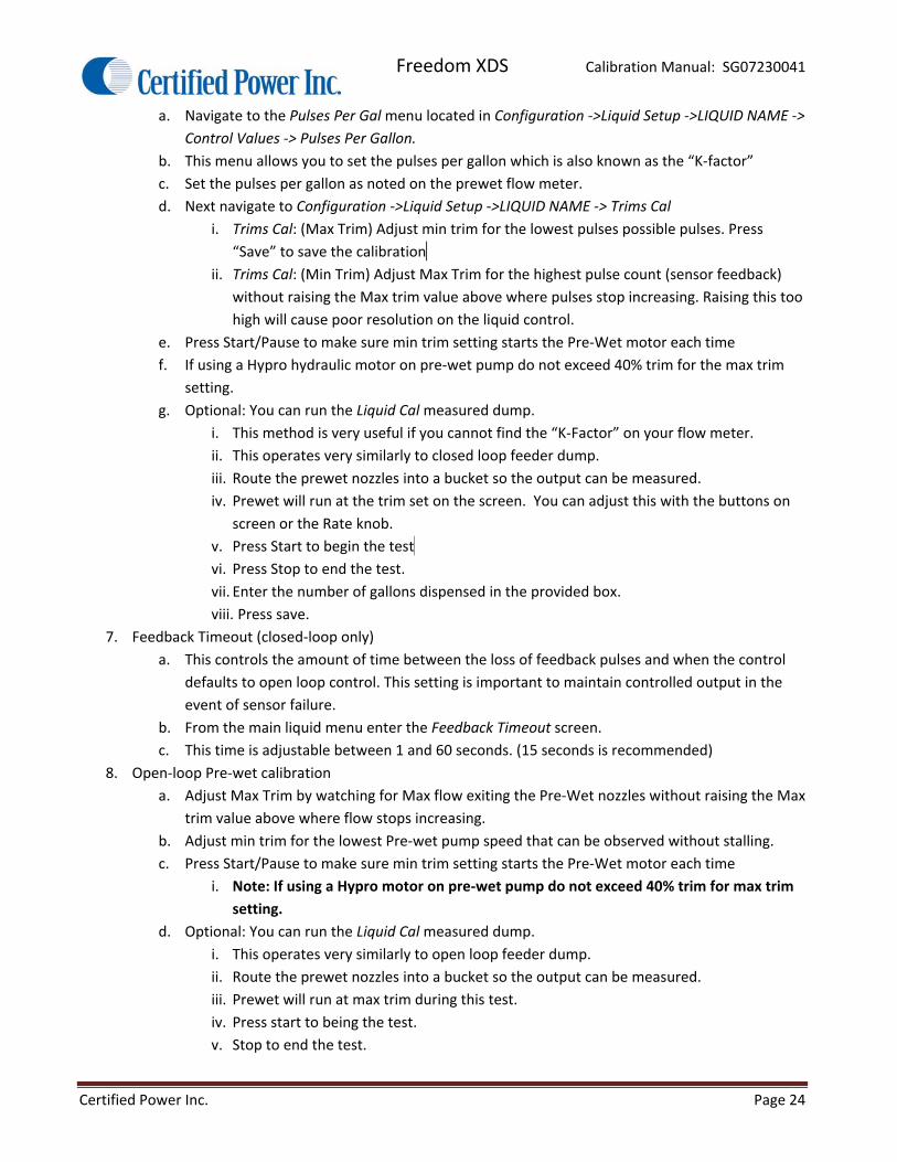
6. Closed‐loop Pre‐wet calibration:
Figure 20: Liquid Trims Calibration Screen
Figure 21: Liquid Measured Dump Screen
Freedom XDS Calibration Manual: SG07230041
Certified Power Inc. Page 24
a. Navigate to the Pulses Per Gal menu located in Configuration ‐>Liquid Setup ‐>LIQUID NAME ‐>
Control Values ‐> Pulses Per Gallon.
b. This menu allows you to set the pulses per gallon which is also known as the “K‐factor”
c. Set the pulses per gallon as noted on the prewet flow meter.
d. Next navigate to Configuration ‐>Liquid Setup ‐>LIQUID NAME ‐> Trims Cal
i. Trims Cal: (Max Trim) Adjust min trim for the lowest pulses possible pulses. Press
“Save” to save the calibration …
ii. Trims Cal: (Min Trim) Adjust Max Trim for the highest pulse count (sensor feedback)
without raising the Max trim value above where pulses stop increasing. Raising this too
high will cause poor resolution on the liquid control.
e. Press Start/Pause to make sure min trim setting starts the Pre‐Wet motor each time
f. If using a Hypro hydraulic motor on pre‐wet pump do not exceed 40% trim for the max trim
setting.
g. Optional: You can run the Liquid Cal measured dump.
i. This method is very useful if you cannot find the “K‐Factor” on your flow meter.
ii. This operates very similarly to closed loop feeder dump.
iii. Route the prewet nozzles into a bucket so the output can be measured.
iv. Prewet will run at the trim set on the screen. You can adjust this with the buttons on
screen or the Rate knob.
v. Press Start to begin the test .
vi. Press Stop to end the test.
vii. Enter the number of gallons dispensed in the provided box.
viii. Press save.
7. Feedback Timeout (closed‐loop only)
a. This controls the amount of time between the loss of feedback pulses and when the control
defaults to open loop control. This setting is important to maintain controlled output in the
event of sensor failure.
b. From the main liquid menu enter the Feedback Timeout screen.
c. This time is adjustable between 1 and 60 seconds. (15 seconds is recommended)
8. Open‐loop Pre‐wet calibration
a. Adjust Max Trim by watching for Max flow exiting the Pre‐Wet nozzles without raising the Max
trim value above where flow stops increasing.
b. Adjust min trim for the lowest Pre‐wet pump speed that can be observed without stalling.
c. Press Start/Pause to make sure min trim setting starts the Pre‐Wet motor each time
i. Note: If using a Hypro motor on pre‐wet pump do not exceed 40% trim for max trim
setting.
d. Optional: You can run the Liquid Cal measured dump.
i. This operates very similarly to open loop feeder dump.
ii. Route the prewet nozzles into a bucket so the output can be measured.
iii. Prewet will run at max trim during this test.
iv. Press start to being the test.
v. Stop to end the test.

Freedom XDS Calibration Manual: SG07230041
Certified Power Inc. Page 25
vi. Enter the number of gallons dispensed in the provided box.
vii. Press save.
9. ON/OFF open‐loop Pre‐wet calibration
a. On/Off Pre‐wet used for Hydraulic ratio Pre‐wet systems, single speed electric motors, or
relays.
b. Output runs at Max trim value. Max trim typically set to 100%.
c. Output turns ON/OFF with Feeder, ground‐speed and Tank empty inputs.
10. Tank Delay
a. Tank delay is the amount of time the prewet float indicates the tank is empty before the
prewet is automatically shut down by the controller. The delay is designed to eliminate
pulsation caused by tank slosh.
b. This can be set between 1‐60 seconds.
c. 5 seconds is the recommended setting.
11. Liquid Shutdown speed
a. This is used to determine the speed at which the prewet is automatically disabled
b. Can be set from 0‐120 mph.
Anti‐IceCalibration1. Checklist: Before starting calibration.
a. Fill tanks with liquid.
i. Caution: Water will freeze causing major damage to all system components.
ii. If water is to be used for calibration, be sure to flush system thoroughly with
windshield washer fluid when calibration is completed to remove all water.
b. All typical plumbing and nozzles must be attached. Be sure nozzles are clean.
c. Move the vehicle to a location where it’s ok to dispense liquid materials.
d. Electric pump motors can be driven directly by the FXDS. Valve Frequency is automatically set
to 300Hz and current will be internally limited to 6 amps. Amp loads higher than 6A require a
Solid State Relay (SSR).
e. Ensure the liquid type is set to “Anti‐Ice” in the Liquid Type menu
f. If you’re using an electric motor or a SSR you must run the “Open Loop Mode” for liquid as
UNCOMPENSATED
g. NOTE: FOR ALL ANTI‐ICE CALIBRATION ALTEAST ONE LANE SWITCH MUST BE ACTIVE FOR
THE PUMP TO OPERATE
2. Closed‐loop Anti‐ice calibration:
a. Navigate to the Pulses Per Gal menu located in Configuration ‐>Liquid Setup ‐>LIQUID NAME ‐>
Control Values ‐> Pulses Per Gallon.
b. This menu allows you to set the pulses per gallon which is also known as the “K‐factor”.
c. Set the pulses per gallon as noted on the prewet flow meter.
d. Next navigate to Configuration ‐>Liquid Setup ‐>LIQUID NAME ‐> Trims Cal.
i. Trims Cal: (Max Trim) Adjust min trim for the lowest pulses possible pulses. Press
“Save” to save the calibration.
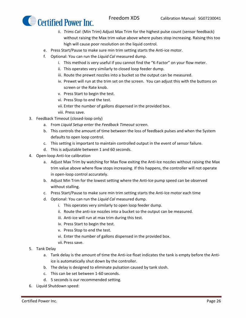
Freedom XDS Calibration Manual: SG07230041
Certified Power Inc. Page 26
ii. Trims Cal: (Min Trim) Adjust Max Trim for the highest pulse count (sensor feedback)
without raising the Max trim value above where pulses stop increasing. Raising this too
high will cause poor resolution on the liquid control.
e. Press Start/Pause to make sure min trim setting starts the Anti‐ice motor.
f. Optional: You can run the Liquid Cal measured dump.
i. This method is very useful if you cannot find the “K‐Factor” on your flow meter.
ii. This operates very similarly to closed loop feeder dump.
iii. Route the prewet nozzles into a bucket so the output can be measured.
iv. Prewet will run at the trim set on the screen. You can adjust this with the buttons on
screen or the Rate knob.
v. Press Start to begin the test.
vi. Press Stop to end the test.
vii. Enter the number of gallons dispensed in the provided box.
viii. Press save.
3. Feedback Timeout (closed‐loop only)
a. From Liquid Setup enter the Feedback Timeout screen.
b. This controls the amount of time between the loss of feedback pulses and when the System
defaults to open loop control.
c. This setting is important to maintain controlled output in the event of sensor failure.
d. This is adjustable between 1 and 60 seconds.
4. Open‐loop Anti‐Ice calibration
a. Adjust Max Trim by watching for Max flow exiting the Anti‐Ice nozzles without raising the Max
trim value above where flow stops increasing. If this happens, the controller will not operate
in open‐loop control accurately.
b. Adjust Min Trim for the lowest setting where the Anti‐Ice pump speed can be observed
without stalling.
c. Press Start/Pause to make sure min trim setting starts the Anti‐Ice motor each time
d. Optional: You can run the Liquid Cal measured dump.
i. This operates very similarly to open loop feeder dump.
ii. Route the anti‐ice nozzles into a bucket so the output can be measured.
iii. Anti‐ice will run at max trim during this test.
iv. Press Start to begin the test.
v. Press Stop to end the test.
vi. Enter the number of gallons dispensed in the provided box.
vii. Press save.
5. Tank Delay
a. Tank delay is the amount of time the Anti‐ice float indicates the tank is empty before the Anti‐
ice is automatically shut down by the controller.
b. The delay is designed to eliminate pulsation caused by tank slosh.
c. This can be set between 1‐60 seconds.
d. 5 seconds is our recommended setting.
6. Liquid Shutdown speed:

Freedom XDS Calibration Manual: SG07230041
Certified Power Inc. Page 27
a. This is used to determine the speed at which the Anti‐Ice is automatically disabled
b. Can be set from 0‐120 mph.
SavingandRestoring(CalibrationandConfiguration)
USBDriveRecommendations1. The FXDS features a USB port for saving and restoring files via a thumb drive
a. Calibration
b. Configuration
c. Firmware (restore only)
d. Storm Totals (save only)
2. The USB Drive should be formatted as FAT or FAT32
a. If using FAT32 format your drive to have an allocation size of the following for best
performance.
i. 16kB
ii. 32kB
b. If you don’t know the format or how to format your thumb drive contact your IT
administrator.
3. It is recommended to use a thumb drive from one of the following vendors
a. PNY
b. SanDisk
c. Patriot
d. Corsair
e. Kingston
f. Transcend
g. Crucial
Save/RestoreProcess1. This menu is located inside the System Setup menu and contains many powerful software
management tools. The most useful to a Technician are described below.
2. Configuration
a. Allows you to save and restore configurations
b. It is recommended that you save your configuration after the unit is calibrated and keep it in a
safe place in case of unit failure.
c. Save will save the file to a thumb drive
i. The file name is A2APPCFG.BIN
ii. There is only 1 file of this type permitted on a thumb drive. If you have multiple trucks
with different configurations you will need a fresh thumb drive or remove the previous
files before backing up another truck.
d. Restore will restore a saved configuration already on the thumb drive.
i. This is useful if you have a fleet of trucks with identical setups.
ii. You can setup 1 truck and then flash the configuration onto all of the other trucks .
3. Calibration
Freedom XDS Calibration Manual: SG07230041
Certified Power Inc. Page 28
a. Allows you to save and restore calibrations.
b. It is recommended that you save your calibration after the unit is setup and keep it in a safe
place in case of unit failure.
c. Save will save the file to a thumb drive
i. The file name is A2APPCAL.BIN
ii. There is only 1 file of this type permitted on a thumb drive. If you have multiple trucks
with different calibrations you will need a fresh thumb drive or remove the previous
files before backing up another truck.
d. Restore will restore a saved configuration already on the thumb drive.

Freedom XDS Calibration Manual: SG07230041
Certified Power Inc. Page 29
GlossaryAuto Mode: The Driver sets a feed rate in lbs/lane mile. The system automatically increases/decreases the
material feed rate with the increase/decrease in ground speed. Feed rate will also change with the
selected lanes if the Lane Mode for the Spinner is active.
Blast: A temporary increase in the Feed rate to cover areas where additional material is critical.
Closed Loop: The control configuration where feedback is provided by a sensor which directly relates to the
shaft speed of the machinery. This feedback is used to ensure the operation is running at the correct
speed to provide accurate and repeatable material feed at all times. Feedback is generally provided
by the auger speed sensor or liquid flow meter.
Firmware: Software that runs the Freedom 2. It is upgradeable via the USB port on the side of the unit.
Ground Speed Oriented: Spreader will automatically adjust output rate based on ground speed. This is only
available in “Auto” mode.
Ground Speed Triggered: Spreader control will automatically turn on when ground speed is detected (vehicle moving) and off when ground speed is lost (vehicle stopped).
Liquid Shutdown Speed: The speed at which the liquid system is automatically turned off by the controller.
Low Voltage Speed Sensor: See Mechanical Source.
Manual Mode: Driver directly sets feed rates based on available trim. There is no change of material feed rate
with the change in ground speed.
Measured Dump: The procedure used to configure the spreader for automatic mode operation.
Mechanical Source: Ground speed type used in applications where the vehicle speed signal source is the vehicle’s computer. Always check with the vehicle manufacturer before attaching to any vehicle wiring.
Mechanical Sink: This setting is used for after‐market hall‐sensors or 12v pulse signals. Also can limit interference on the ground speed input that causes erratic or erroneous ground speed indication.
Open Loop: The control configuration where no sensor is installed on the auger or conveyor shaft. Without shaft speed feedback there can be small variances in speed of the motor which the system cannot sense. These small variances will lead to small spreading inaccuracies.
Open Reference: A value in Amps at which the Freedom 2 will determine if a circuit is open (no connection) at.
This is individually set for each of the 3 PWM outputs. This should usually be set to 0.1 Amps for
traditional valve coils. If using a solid state relay set this to zero.
Speed Threshold: This variable changes the size of a speed change required for the Freedom 2 to react. 0.5 is
the recommended setting.
Freedom XDS Calibration Manual: SG07230041
Certified Power Inc. Page 30
Start Percent: A boost to the output at initial turn on to give the function a “kick start”. Start Percent is only
enabled in closed loop until pulse feedback is sensed. In open loop mode start percent stays on for
the set timeout duration.
Tank Delay: Tank delay is the amount of time the prewet float indicates the tank is empty before the prewet is
automatically shut down by the controller.
Trim: The calibrated range of PWM frequency that is permitted via calibration. Generally minimum trim is the
minimum rate at which the function just starts to move. Maximum trim is the rate at which further
increase of the output PWM has no effect on the driven function. Maximum trim can also be set
lower if desired.
Unload Mode: Unload mode has identical functionality as Manual Mode except it does not write material data into logs. Use “unload mode” instead of manual mode to UNLOAD the vehicle at the yard. This will keep the Storm and Annual Totals from being mistakenly written into, generating false Granular and Liquid spread data. The controller limits the vehicle speed while unloading to less than 5 mph or the controller will be kicked back into Auto mode/pause.
Valve Frequency: This is the PWM frequency that the spreader control uses to drive the valve. All systems are different and no two have the same characteristics so there are no set in stone values to use for this. As rule of thumb however 180Hz is a good starting point when setting PWM frequency.
VRM: A ground speed setting used for Low voltage AC signals. This type of input can be susceptible to noise and the wiring should be shielded with a drain path to chassis ground.

Freedom XDS Calibration Manual: SG07230041
Certified Power Inc. Page 31
AppendixI:FXDSErrorsSetting not Saved, Min exceeds Max: This is a common message seen while saving trims. Usually occurs if
saving a minimum trim percent that is over the maximum trim percent. Try setting max trim first then
set minimum trim last. The error also appears if no feedback is being received from the closed‐loop
sensor when a Save is applied.
Ground Speed Error: This error appears if trying to save a “Speed Cal” and not having any groundspeed signal
present at the MPH Ground Speed input. Try a different “Speed Type” and watch for the “Pulses Per
minute” value to reflect a frequency indicating a good groundspeed signal at the input.
Sensor Power Error: If the sensor power supply line is shorted to ground or has more than 750mA. of current
draw the sensor power supply from the FXDS is being overloaded. Suspect a faulty Feeder sensor or
Liquid Flow‐meter sensor. Also suspect a pinched or crushed wire, corroded connector or any fault
that may cause a short to chassis ground.
Feeder Rate limited: If the Feeder is running at max speed and the current target application rate is NOT being
met, this error will display. Sometimes this error would be indicative of a system that has not been
calibrated or has been calibrated improperly. This error also applies to Liquid, and the Spinner. This
error clears itself when the target rate is being met.
Feeder Rate Overrun: If the Feeder is running at its lowest speed and the current target application rate is
NOT being met, this error will display. Sometimes this error would be indicative of a system that has
not been calibrated or has been calibrated improperly. This error also applies to Liquid, and the
Spinner. Usually this error will only display at very low sustained vehicle speeds of usually 5mph or less
and low target rates. This error clears itself when the target rate is being met.
Sensor fault and Feeder Override: This error occurs when the FXDS was operating in closed‐loop mode and
was not receiving sensor feedback. The FXDS automatically defaults into open‐loop after this error
occurs. Suspect a stalled motor or conveyor, or dry or stalled liquid pump. This could also be caused by
a failed sensor or faulty harness. This error occurs for any closed‐loop function. The error condition is
cleared with a power cycle.
Liquid Tank Empty: The liquid tank is empty

Freedom XDS Calibration Manual: SG07230041
Certified Power Inc. Page 32
AppendixII:ImportantReferenceDocumentsandPartNumbersSG07230040: FXDS Operator’s Manual
SG07230041: FXDS Calibration Manual
SG07010488: FXDS Display Product Document
SG07010489: FXDS Operator Panel Product Document
SG07010515: FXDS output module Product Document
SGS00800600001: BSP image, rename to rom.bin before flashing firmware
SGS00800600002: Main image, rename to image.bin before flashing firmware
SGS00800600003: Backup image, rename to backup.bin before flashing firmware
SGS00800200001: Output Module firmware: NODE1
SGS00800300001: Output Module firmware: NODE2
SGS00800400001: Output Module firmware: NODE3
SGS00800500001: Output Module firmware: NODE4
SGS00800700001: FXDS Operator Panel Firmware