Embed Size (px)
Citation preview

Free Transverse Vibration Analysis of
thin rectangular plates having arbitrarily
varying non-homogeneity along two
concurrent edge
Avinash Kumar
MECHANICAL ENGINEERING
National Institute of Technology, Rourkela

I
Free Transverse Vibration Analysis of
thin rectangular plates having arbitrarily
varying non-homogeneity along two
concurrent edge
Thesis submitted in partial fulfilment of the requirements for the degree of
Master of Technology
in
Mechanical Engineering with Specialization in Machine Design and
Analysis
BY
AVINASH KUMAR
Roll Number (216ME1349)
based on research carried out under supervision of
Prof. R.K BEHERA
May 2018
Department of Mechanical Engineering
National Institute of Technology Rourkela Odisha 769008

II
MECHANICAL ENGINEERING
National Institute of Technology, Rourkela
Prof. R.K Behera
Associate Professor May 24, 2018
Supervisor’s Certificate
This is to certify that the work presented in the thesis entitled Free Transverse Vibration
Analysis of thin rectangular plates having arbitrarily varying non-homogeneity along
two concurrent edge submitted by AVINASH KUMAR, Roll Number 216ME1349, is a
record of original research carried out by him under my supervision and guidance in partial
fulfilment of the requirements of the degree of Master of Technology in MACHINE
DESIGN AND ANALYSIS. Neither this thesis nor any part of it has been submitted earlier
for any degree or diploma to any institute or university in India or abroad.
Prof. R.K BEHERA
Dept. of Mechanical Engineering
National Institute of Technology, Rourkela

III
Dedication
Dedicated to my beloved family
IV
Declaration of Originality
I, AVINASH KUMAR, Roll Number 216ME1349 hereby declare that this thesis entitled
Free Transverse Vibration Analysis of thin rectangular plates having arbitrarily varying
non-homogeneity along two concurrent edge presents my original work carried out as a
Postgraduate student of NIT Rourkela and, to the best of my knowledge, contains no
material previously published or written by another person, nor any material presented by
me for the award of any degree or diploma of NIT Rourkela or any other institution. Any
contribution made to this research by others, with whom I have worked at NIT Rourkela or
elsewhere, is explicitly acknowledged in the dissertation. Works of other authors cited in
this dissertation have been duly acknowledged under the sections “Reference” or
“Bibliography”. I have also submitted my original research records to the scrutiny
committee for evaluation of my dissertation.
I am fully aware that in case of any non-compliance detected in future, the Senate of NIT
Rourkela may withdraw the degree awarded to me on the basis of the present dissertation.
May 24, 2018
NIT Rourkela
Avinash Kumar
V
ACKNOWLEDGEMENTS
The two years I spent at the National Institute of Technology have been full of unforgettable
memories. Thanks to many people who deserve my highest gratitude.
I would like to express our deep sense of gratitude to our supervisor Prof. R.K BEHERA
for giving us this opportunity to work under him. Each and every discussion with him has
been very educative. We are very thankful to him for the patience he had with us and for
giving us absolute freedom in doing our task. We shall remain indebted to him for his
constant support and guidance.
We are thankful to Prof. D R PARHI, Head of the Department, Department of
MECHANICAL Engineering for providing us with necessary facilities for the research
work.
I would also like to express my gratitude to PhD Scholar KRISHANU GANGULY and for
his generous help for the completion of this project.
I would like to thank all my classmates and my friends especially. BIREN KUMAR
PRADHAN, SATYABRATA NAYAK and ABHISHEK PATRA. A truly unbounded
words of thanks to my family for their affection, constant encouragement and forbearance.
Finally, I bow myself to Almighty God whose blessings guard and guide me throughout my
life.
May 24, 2018
NIT Rourkela
Avinash Kumar

VI
ABSTRACT
In this paper, I presented the analysis and numerical results for free transverse vibration of
thin rectangular plates having arbitrarily varying non-homogeneity with the in-plane
coordinates along the two concurrent edges. For finding the general governing differential
equation first used the Kirchhoff’s plate theory by considering their assumptions.
After finding the governing equation for the plate. For the non- homogeneity a linear
variation for Young’s modulus and density of the plate has been assumed. Finite difference
method (FDM) has been used to obtain the eigen value problem for such model plate for
two different boundary condition at the edge namely (i) CCCC fully clamped (ii) CSCS two
opposites are clamped and other two are simply supported.
By solving these eigen value problem using MATLAB, the lowest three eigen value have
been reported as the first three natural frequencies for the three mode of vibration. The effect
of various plate parameters such on the vibration characteristics has been analysed. Three
dimensional mode shape has been plotted.
Keywords: Non-homogeneity, flexural rigidity, FDM, Non-dimensional frequency parameters

VII
CONTENTS Supervisor’s Certificate ....................................................................................................... II
Dedication ........................................................................................................................... III
Declaration of Originality ................................................................................................... IV
ACKNOWLEDGEMENTS ................................................................................................. V
ABSTRACT ....................................................................................................................... VI
Chapter-1 .............................................................................................................................. 1
1. Introduction .................................................................................................................. 2
Plate structure ................................................................................................................... 2
1.2 Background ............................................................................................................ 2
1.3 Present Work .......................................................................................................... 3
1.4 Novelties of this paper ........................................................................................... 4
Chapter 2 ............................................................................................................................... 5
2.1. Literature Review ................................................................................................... 6
Chapter 3 ............................................................................................................................. 11
3.1. Mathematical Formulation ................................................................................... 12
3.1.1 Kirchhoff- love plate theory ......................................................................... 12
3.1.2 Assumption ................................................................................................... 12
3.1.3 Consideration of Non-homogeneity ............................................................. 18
3.2 Boundary Condition ............................................................................................. 18
3.2.1 Clamped edge ............................................................................................... 19
3.2.2 Simply Supported edge ................................................................................. 19
Chapter 4 ............................................................................................................................. 20
4.1. Method of Solution .................................................................................................. 21
4.1.1. Method of Solution Using FDM Technique ................................................. 21
Chapter 5 ............................................................................................................................. 26
5.1.NUMERICAL RESULT AND DISCUSSION ........................................................ 27
Chapter 6 ............................................................................................................................. 36
6.1. Conclusion ............................................................................................................... 37
6.1.1 Observation ........................................................................................................ 37
6.1.2. Future Work ...................................................................................................... 37
References ...................................................................................................................... 39
VIII
List of Figure
Figure 1 Geometric of the isotropic plate ........................................................................ 12
Figure 2 Force (intensity) acting on the plate element ................................................... 13
Figure 3 Moment (intensity) acting on the plate element .............................................. 13
Figure 4 shows the deformed middle surface of the plate element showing slopes and
their change ....................................................................................................................... 14
Figure 5 Kinematics of plate deformation ....................................................................... 15
Figure 6 Boundary condition ............................................................................................ 19
Figure 7 Grid point distribution on a rectangular domain ........................................... 21
Figure 8 Demonstration of interior points, adjacent points and boundary of a
rectangular plates ............................................................................................................. 22
Figure 9 Frequency parameters versus non-homogeneity parameters 1 for a
square CCCC plate for 1 2 0.5 , for the first, second and third mode
respectively ........................................................................................................................ 30
Figure 10 Frequency parameters versus non-homogeneity parameters 1 for a
square CSCS plate for 1 2 0.5 , for the first, second and third mode
respectively ........................................................................................................................ 30
Figure 11 Frequency parameters versus non-homogeneity parameters 1 for a
CCCC square 1 2 0.5 , for the first, second and third mode respectively ........ 31
Figure 12. Frequency parameters versus non-homogeneity parameters 1 for a
CSCS square 1 2 0.5 , for the first, second and third mode respectively .......... 31
Figure 13 frequency parameters versus aspect ratio for CCCC plate ................... 33
Figure 14 frequency parameters versus aspect ratio for CSCS plate ..................... 33
Figure 15 Mode shape ........................................................................................................ 34

IX
List of Table
Table 1 Convergence of frequency Parameters with the grid points ,N M for
homogeneous 1 1 2 2 0 square plate .......................................................... 27
Table 2 Convergence of frequency Parameters with the grid points ,N M for
homogeneous 1 1 2 20.5, 0 square / 1a b plate .................................... 28
Table 3 Convergence of frequency Parameters with the grid points ,N M for
homogeneous 1 1 2 2 0.5 square / 1a b plate ...................................... 29

X
LIST OF ACRONYMS
, ,x y z Cartesian coordinate system
, , ,X Y H W Non dimensional variables
,x yQ Q
Transverse shearing force per unit length in the respective
direction
, ,x y xyN N N
In-plane Normal and Shear force per unit length
,x yM M, xyM
Bending moment and twisting moment intensities per
unit length
,q x y
Transverse external force per unit area
, ,w x y t
Displacement function in z-direction
, ,a b h Length, width and thickness of the plate
,X Y
Mass density function
2
2
w
t
Acceleration in z-direction
,E X Y
Young’s modulus function
, ,x y xy
Normal and shear strain in the respective direction
,D D x y
Flexural rigidity function
Poisson’s ratio
/a b Aspect ratio
1 2,
Non-homogeneity parameters
1 2,
Density parameters
0 0,E
Young’s modulus and density of the plate material at
0X and 0Y
, , ,p q r s Positive integers
,N M Number of grid points in x any y direction
Circular frequency
Non- dimensional frequency parameters
C Clamped
S Simply supported
,X Y Equally spaced grid length and width
,W i j Non dimensional displacement at ,i j points
LVN Linear Variation Non-homogeneity
PVN Parabolic Variation Non-homogeneity

1
Chapter-1
INTRODUCTION

2
1.Introduction
Plate structure
Plate structure element is characterised by its property such as, it is a three dimensional solid
whose thickness is very small as compared to the other dimensions and the effects of the
load that applied on it generate the stresses which are generally normal stress only. The plate
bounded by the two parallel planes, and the distance between the plate is called the thickness
of the plate. The 2D plate theory give the approximate results such as 3D plate like structure.
Because the one dimension of the plate is very less compared to other two dimension of the
plate. So it is a plain stress condition in which the stresses like 0z z zx zy . Along
with the stresses the shear strain yz xz is also zero.
1.2 Background
Several years ago, in the aerospace field an engineer needed to know the first three
frequency and mode shape of a rectangular plate of a certain aspect ratio along with the
certain boundary condition. After various literature search for several weeks, they only get
two first frequency but not get any accurate mode shape. Since he had neither the analytical
capability of solving the problem nor the money and time needed for experimental
programme.
Since we know that, as the technology is increasing rapidly, the requirement of the advanced
material is also at a high demand due to their extensive use in the engineering applications,
especially for the performance in the high temperature environment. Because these material
are stiffer, stronger and corrosion resistance. This literature provides free vibration analysis
of thin rectangular isotropic plate having arbitrarily varying non-homogeneity with the in-
plane coordinates along the two concurrent edges.
But now-a-days, technologists are able to tailor advanced material by mixing two or more
materials to get the desired properties along the one/more direction due to their extensive
demand in the many field of modern engineering applications, and especially for
performance in the high temperature environment. Usually, these materials are stiffer,
stronger and corrosion resistant than the other conventional material used earlier. The

3
structural element made up of such material will be non-homogeneous by nature in which
the material properties may vary continuously in a certain manner either along a line or in a
plane or in a space. During the past few decades, due to development of high speed digital
computer and numerical methodologies a huge amount of work analysing the dynamic
behaviour of the plates of various geometries with different boundary condition. Despite the
aforementioned researches on the vibration of the non- homogeneous rectangular plates,
there exists very few researches in which two-dimensional (2D)- arbitrary variation for the
non-homogeneity of the plate material has been considered.
1.3 Present Work
The present work is done to fill this gap of isotropic plate with the uniform thickness. For
such plate model, the governing differential equation of motion has been solved employing
the Finite Difference Method (FDM). Further, this consideration for non-homogeneity
together with aspect ratio of the plate shows their effect on the natural frequencies for the
all possible combination of the classical boundary condition at the four edge of the plate
material.
But, in this paper linear model for non-homogeneity of the isotropic material have been
considered assuming that the Young’s modulus and density are varying in same distinct
manner along the both in plane coordinates. The non-homogeneity arises due to arbitrary
variation in Young’s modulus and density. All of these investigation have been taking
poison’s ratio as constant. This type of non-homogeneity arises during the fibre reinforced
plastic structure, which use fibre of different strength properties along two mutually
perpendicular directions along the edges of the plate.
Since we know that there are totally 21 possible boundary conditions for a rectangular plate.
this will generate a huge data therefore in this present work, the numerical computation has
been carried out only for the two boundary condition, namely (i) CCCC- all the four edge
are clamped, (ii) CSCS- two opposite edges are simply supported and the other opposite
edges are clamped with the linear variation of Young’s modulus and the density. The effect
of non-homogeneity parameters, density parameters and the aspect ratio on the natural
frequencies has been investigated for the first three modes of vibration.

4
1.4 Novelties of this paper
(i) Plate type structure of 2D model for the non-homogeneity has been proposed.
(ii) The Young’s modulus and density of the plate material are assumed as a function
of in-plane coordinates x and y.
(iii) The proposed model encompasses various unidirectional/bidirectional, linear
and non-linear models.
(iv) FDM solution has been obtained successfully to find the mode shape of this
model plate structure Natural frequency found by using the Rayleigh method
with deflection function as a product of beam function.
(v) This analysis may be useful for missiles and aircraft designers, solid state
physicist and, in general people engaged in material science.

5
Chapter 2
Literature Review

6
2.1. Literature Review
Since we know that, as the technology is increasing rapidly, the requirement of the advanced
material is also at a high demand due to their extensive use in the engineering applications,
especially for the performance in the high temperature environment. Because these material
are stiffer, stronger and corrosion resistance. This literature provides free vibration analysis
of thin rectangular isotropic plate having arbitrarily varying non-homogeneity with the in-
plane coordinates along the two concurrent edges.
The study of non-homogeneous material with fair amount of accuracy is of practical
importance from the view point of design engineers. In this regard, the earliest model for
the non-homogeneity was proposed by Bose [1] in which Young’s modulus and density of
the plate material are supposed to vary with the radius vector i.e. ( , ) = ( 00 , )r. An
approximate solution is obtained using Ritz method. The frequency parameter Ω is found
to increase with the increase in non-homogeneity parameter as well as taper parameter,
while it decreases with the increase in density parameter.
Later on, Biswas [2] developed a model for non-homogeneity considering the exponential
variation for torsional rigidity z
e 1
0
and the material density
ze 1
0
, where
00 , and 1 are constants. DQM (Differential Quadrature Method) has been used to
analyse the free vibration of non- homogeneous orthotropic rectangular plate of parabolic
varying thickness resting on Winkler foundation.
Das and Mishra [3] deals with the transverse vibration of elliptical and circular plate using
two dimensionally boundary characteristics orthogonal polynomial using Rayleigh Ritz
method by considered the non-homogeneity of the plate characterized by taking Young’s
modulus Z 10 and density 2
0 1
Z , 10 and is an integer
greater than 3.
Rao et al. [4] proposed a model for non-homogeneous isotropic thin plate by assuming linear
variation for Young’s modulus and density given by x 10 and x 10 ,
being constant.

7
The free transverse vibration of non -homogeneous circular plate of linearly varying
thickness on the basis of classical plate theory has been analysed with help of Tomar JS,
Gupta DC and Jain NC [5]. In which The frequency parameter increases with increase the
rate of increase for free plate is higher than simply-supported plate but lesser than clamped
plate.
The Natural frequencies for free vibration of non-homogeneous elliptic and circular plates
using two-dimensional orthogonal polynomials has been analyse with help of Chakravety
and Pety [6]. In this paper the non- homogeneity is taken by considering linear variation of
the Young’s Modulus and parabolic variation of the density of the material. The first five
natural frequencies have been analysed in this paper.
Effect of non-homogeneity on asymmetric vibrations of non-uniform circular plates has
been analysed by Seema Sharma, R. Lal, Neelam Singh [7] where the non-homogeneity
arises due to exponential variation of the Young’s modulus as well as density parameters
along the radial direction. The first three natural frequencies are found with using of Ritz
method. The effect of the taper parameters and the density parameters has been analysed in
this paper.
Free transverse vibrations of nonhomogeneous orthotropic rectangular plates with bilinear
thickness variation resting on Winkler foundation are presented by Yazuvendra kumar, R.
Lal [8] by using two dimensional boundary characteristics orthogonal polynomial using
Rayleigh Ritz method on the basis of classical plate theory. Orthogonal polynomial has been
generated by using Gram-Schmidt. The non-homogeneity is considering by taking the linear
variation of the Young’s modulus as well as density. The two dimensional thickness
variation is considered by taken Cartesian product of linear variation. In the previous all
literature papers there is assumption taken that the Poisson’s ratio is constant throughout.
However, in the two studies Rossi and Laura [9] it has been found that effect of the Poisson’s
ratio on the frequency is not appreciable and reported as considerably less than 1%.
Free vibration analysis of clamped orthotropic plate material using Lagrangian multiplier
technique by R. L Ram Kumar et al., [10]. Transverse shear deformation effects were
included using a higher-order plate theory. The validated free vibration analysis has also
been used to develop an analysis to predict the dynamic response of clamped orthotropic
plates subjected to low-velocity impact by a hard object. Effect of non-homogeneity
parameters, aspect ratio and thickness variation together with foundation parameter on the

8
natural frequencies has been illustrated for the first three modes of vibration for four
different combinations of clamped, simply supported and free edges correct to four decimal
places.
The hierarchical finite element method is used to determine the natural frequencies and
modes of a flat, rectangular plate by Bardell [11] Ten different boundary conditions—
including free edges and point supports—are considered in this paper. Extensive results are
presented for each case (including the variation of frequency with the aspect ratio and the
Poisson ratio), and these are shown to be in very good agreement with the work of other
investigators. This confirms both the applicability and accuracy of solution of the HFEM to
problem of this type.
Kantorovich method has also been used to find the natural frequencies of orthotropic
rectangular plates Sakata et al., [12]. In this method the natural frequencies are obtained by
the successive reduction of the plate partial differential equation and by solving the results.
The reduction of the partial differential equation is obtained by assuming an approximate
solution satisfying the boundary condition along the one direction and then apply the
Kantorovich method.
Vibration analysis of laminated composite plates on elastic foundations by Ishan
kucukrendeci and Hasan Kucuk [13]. In this study the composite plates consist of layers and
layer are arranged at different angles. And this plate supported by the springs of five
different points. The finite element method is used to find the natural frequencies of this
plate model. The boundary condition of the plate having three different conditions i.e
clamped, simply supported and free edge. MATLAB is used to solve the equation.
Free vibration analysis of rectangular plates with variable thickness M. Huang [14]. In this
paper an approximate method which is based on the Green function of a ate plate is used.
The Green function of a rectangular plate with arbitrary variable thickness is obtained as a
discrete form of solution for the deflection of the plate with concentrated load. The solution
is obtained at each discrete point which are equally distributed on the plate. After applying
the green function, the free vibration of the plate converted into the eigen value problem of
matrix. The convergence an accuracy of the numerical solution for the natural frequencies
parameters calculated by the proposed method.
Hybrid method for the vibration analysis of the rectangular plate by Kerboua et al., [15].
This paper basically related to the dynamic analyses of the rectangular plates. Mathematical

9
model is developed by the hybrid method and finite element method and Sander’s shell
theory is used to find out the frequency of this plate material. The in plane displacement
membrane component is modelled by bilinear polynomials and the out of plane, normal to
the mid plane displacement component is modelled by an exponential function. the
displacement function is obtained by the exact solution of the equilibrium equation and the
mass and the stiffness matrices are then determined by exact analytical integration to
established the dynamic plate equation.
Vibration analysis of the structure with Differential quadrature approach by Richard
Bellman et al., [16]. This technique could be utilized in a simple manner to obtain the
solution of non-homogeneous differential equations derived from applications of the theory
of invariant imbedding to transport process. In this paper the ideas offer a new technique
for the numerical solution of initial value problem for the ordinary and partial differential
equations for a certain complex problem
A general boundary condition new approach for implementing the general boundary
condition in the GDQ free vibration analysis of rectangular plates is presented in this paper
by C. Shu, H. Du [17]. In this approach boundary condition is directly coupled with the
governing equation. The accuracy of this approach are demonstrated through its application
to the vibration analysis of a rectangular plate with various combination of free edges and
corners. In this approach the equally spaced grid distribution method has been used to find
the natural frequencies of the plate.
Harmonic differential quadrature method and its application to analyse of structural
components String et al., [18]. This method can be used to analysed the buckling and the
free vibration of the beams and rectangular plates. In this method a new technique is used
to find out the weightage coefficient for the differential quadrature. It is more efficient than
the DQ method especially for the higher order frequencies and the buckling load of the
rectangular plates under the wide range of the aspects ratio.
Kuldeep S. Virdi [19] Finite difference method for nonlinear analysis of Structures. This
paper describes a sustained line of development of methods of nonlinear analysis of
structural element and frames using FDM. This method is also extended to use in composite
frames and structure. A good correlation with this experiment has been obtained for the

10
deflection. Also the problem of nonlinear response of the structure has been successfully
solved.
Analysis of beam by the FDM (Finite Difference Method) Gautam Chattopadhyay [20]. In
this paper studied how the FDM technique can be used to find the deflection and frequency
of the beam at each node of the distributed grid points.
Accuracy study of the FDM by Nancy Jane Cyrus, Robert E. Fulton [21]. In this paper FDM
used for linear differential equation. Definite error for each expression is derived from the
Taylor series. This method is used to assess the accuracy of two alternate forms of central
finite difference approximations for solving the boundary value problem of the structural
analysis which are governed by the certain equations containing variable coefficient.

11
Chapter 3
MATHEMATICAL FORMULATION

12
3.1. Mathematical Formulation
For the mathematical formulation, considered a non-homogeneous isotropic rectangular
plate of uniform thickness h , density yx, having a domain byax 0,0 , where
a and b are length and breadth of the plate respectively. The x-axis and y-axis are taken along
the edge of the plate and the z-axis is perpendicular to the xy- plane. The middle surface
being 0z and the origin is at one of the corners of the plate as shown in figure 2(a).
Figure 1 Geometric of the isotropic plate
3.1.1 Kirchhoff- love plate theory
To find the equation of motion of this plate model. Let us taken the infinitesimal plate of
length, breadth and height dx, dy and h respectively. The Kirchhoff–Love theory of plates is
a two-dimensional mathematical model that is used to determine
the stresses and deformation in thin plates subjected to forces and moments. It is extension
of Euler-Bernoulli beam theory developed by Love in 1988.
3.1.2 Assumption
The assumptions which is used to find the equation of motion of this plate model are-
(i) straight lines normal to the mid-surface remain straight after deformation.
(ii) straight lines normal to the mid-surface remain normal to the mid-surface after
deformation.
(iii) the thickness of the plate does not change during a deformation.

13
Figure 2 Force (intensity) acting on the plate element
The Figure 2 shows transverse shearing force intensities zQ and yQ , the in-plane normal and
shearing force intensities xN , yN and xyN , and their incremental changes are shown acting
on the sides of the element, with positive forces acting in positive directions on positive
faces. The shearing force xyN are identical on the face at x = 0 and y = 0. Because the
shearing stress causing them are equal.
Figure 3 Moment (intensity) acting on the plate element
Figure 3 shows the bending moment and the twisting moment intensities and their
incremental change. The twisting moment xyM are identical on the face at x = 0 and at y =
0. Because the shearing stress causing them are equal

14
.
Figure 4 shows the deformed middle surface of the plate element showing slopes and their change
The figure 4 shows that incremental changes are shown at all the corner of the element with
positive changes assume in positive direction. For small displacement, it is assumed that the
slope and the sine of the angle are equivalent.
For equilibrium summing the forces in z-direction
dydxx
NN
x
wdyNdydx
y
Qdxdy
x
Q xxx
yx
dy
y
w
y
wdxdy
y
NN
y
wdxNdx
x
w
x
w y
yy 2
2
2
2
dy
yx
w
x
wdxdy
y
NN
x
wdxN
xy
xyxy
2
dx
yx
w
y
wdydx
x
NN
y
wdyN
xy
xyxy
2
2
2
t
wdxdyqdxdy
(3.1)
We know that equilibrium equation from theory of elasticity by neglecting the inertial force
and transverse shear stress. because yz and zx are small relative to other stress.
Because these equations must be satisfied for every infinitesimal thickness dz of the plate
element, their integral over the thickness also satisfied
0
yx
xyx
0
yx
yxy
(3.2)
15
0
y
N
x
N xyx
0
y
N
x
N yxy
(3.3)
Using equation (2.3) in equation (2.1), the equilibrium equation in z-direction
2 2 2
2 22
yxx y xy
QQ w w wN N N q
x y x y x y
2
2
t
wh
(3.4)
Similarly, the forces in x and y-direction
2
2
x yxx y
NN w w uQ Q
x y x x y y t
2
2
xy y
x y
N N w w vQ Q
x y x y y y t
(3.5)
Now, moment about x and y-axis are
3 3
2
3 3
2
12
12
x yxx
x y y
y
MM h wQ
x y x t
M M h wQ
x y y t
(3.6)
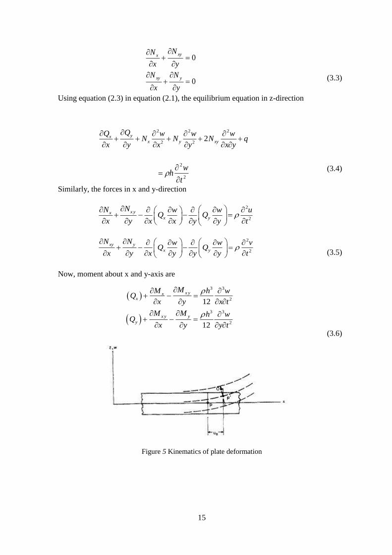
Figure 5 Kinematics of plate deformation

16
An edge view of the portion of the plate material shown in figure. The deformed shape is
shown in broken lines while the un-deformed shape is shown in unbroken lines. The
longitudinal elastic displacement of a point P on the mid-plane is depicted by 0u . The
longitudinal displacement of the points within the plate written as
The strain displacement function is
2
0
2
2
0
2
2
0 0 2
x
y
xy
u u wz
x x x
v v wz
y y y
v u v u wz
x y x y x y
(3.8)
Since we know that for the isotropic material, strain stress relationship is
1
1
2 1
x x y
y y x
xy xy
E
E
E
(3.9)
0
0
wu u z
x
wv v z
y
(3.7)
/2
/2
/2
/2
/2
/2
,
,
,
h
x x
h
h
y y
h
h
xy xy
h
N dz
N dz
N dz
/2
/2
/2
/2
/2
/2
,
,
h
x x
h
h
y y
h
h
xy xy
h
M zdz
M zdz
M zdz

17
Now the force and moment integral for the homogeneous plate is-
With the help of equation, (2.8) and (2.9) get the value of force intensities and moment
intensities.
2 2
2 2
2 2
2 2
2
,
,
1
x
xy
w wM D
x y
w wMy D
y x
wM D
x y
(3.11)
Now using the equation (2.11) in equation (2.6) to find the xQ and yQ
2 2 3 3 2
2 2 3 21x
D w w w w D wQ D
x x y x x y y x y
2 2 3 3 2
2 2 3 21y
D w w w w D wQ D
y y x y x y x x y
(3.12)
Now put the value of xQ , yQ in the equation (2.1), and the in-plane forces are first
determined from the equation (2.10). They are uncoupled each other in case of bending
and stretching. Since the analysis of this plate model is based on free vibration i.e. 0q
.Therefore the equilibrium equation (2.1) will become
2 2
2 2 2 2 2 2
2 2 2 2
2
2
1
2
0
D w
D w D w D w
x y x yx y y x
wh
t
(3.13)
(3.10)

18
Where,
3
2
,,
12 1
E x y hD D x y
3.1.3 Consideration of Non-homogeneity
For the harmonic motion the displacement w is assumed to be
Now for considering the non-homogeneity considering the non-dimensional variables
axX / , byY / , ahH / and awW / . And the variation of the Young’s modulus
and density of the plate material as a function of in-plane coordinate.
sr
qp
YXYX
YXEYXE
210
210
1,
,1,
(3.15)
Thereafter the equation (2.13) reduces to
4 4 4 3 32 4 1 2
1 2 14 2 2 4 3 2(1 ) 2 2p q pW W W W W
X Y p XX X Y Y X X Y
3 3 21 4 2 2 2
2 13 2 2 22 ( 1)q pW W W W
q Y p p XY X Y X Y
2 2
2 2 4 2
2 1 22 2( 1) 1 0q r sW W
q q Y X Y WX Y
(3.16
)
The consideration of this type of non-homogeneity help in complex problem and be practical
use for Geologist to apply it as a tool in examining the heterogeneity of the material.
3.2 Boundary Condition
The two type of boundary condition namely, CCCC and CSCS have been considered where
the symbol C, S denotes the clamped and the simply supported. In a notation such as CSCS
the first symbol indicates the condition at X= 0, the second is at Y= 0, the third at X= 1, the
fourth at Y= 1.
tieyxwtyxw ,,,
(3.14)

19
Figure 6 Boundary condition
3.2.1 Clamped edge
0, 0dW
WdX
at 0X and 1
0, 0dW
WdY
at Y = 0 and 1
(3.17)
3.2.2 Simply Supported edge
2
2 0, 0
d WW
dX at 0X and 1
2
2 0, 0
d WW
dY at 0Y and 1
(3.18)

20
Chapter 4
METHOD OF SOLUTION
21
4.1. Method of Solution All together there are 21 combinations of simple boundary conditions (i.e., either clamped
(C), simply supported (SS), or free (F)) for rectangular plates. Frequency parameter does
not depend upon the Poisson’s ratio until at least one of the edge of the plate is free. However
because D contains , the frequency themselves depends upon for all cases.
4.1.1. Method of Solution Using FDM Technique
Finite difference method is important tool for the analysis of structures. Due to FDM
technique a sustained line of development of methods of nonlinear analysis of structural
element and frames. This method is also extended to use in composite frames and structure.
A good correlation with this experiment has been obtained for the deflection. Also the
problem of nonlinear response of the structure has been successfully solved.
Since we know that the FDM technique is a numerical method to find the approximate
solution of a differential equation. It is very helpful to find the solution of partial differential
equation. In this method at first the problem has to discretized. This is done by dividing the
problem domain into a uniform grid. Therefore, it is also known as discretization method.
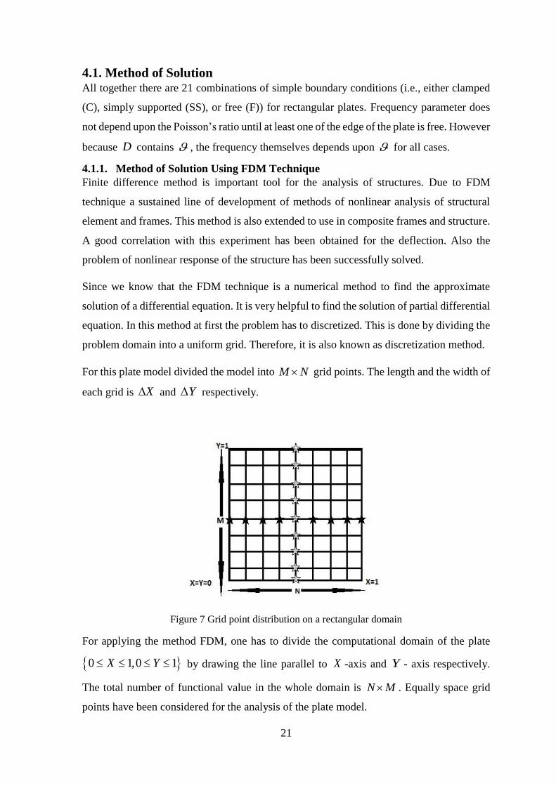
For this plate model divided the model into M N grid points. The length and the width of
each grid is X and Y respectively.
Figure 7 Grid point distribution on a rectangular domain
For applying the method FDM, one has to divide the computational domain of the plate
0 1,0 1X Y by drawing the line parallel to X -axis and Y - axis respectively.
The total number of functional value in the whole domain is N M . Equally space grid
points have been considered for the analysis of the plate model.

22
Figure 8 Demonstration of interior points, adjacent points and boundary of a rectangular plates
Figure (8) shows that number of grid points vary from 1i to N in x-direction and
1j to M in the y-direction. Let choose a grid of coordinate ,i jX Y and displacement
function at that coordinate will be ,W i j . The equation (3.16) have the 4th order partial
differential term of two variables. Now for solving the equation (3.16) by FDM technique
we have to find the value of partial differential part in the form of forward difference.
e.g.
3
3 3
3
3 3
2, 2, 2 1, 1,,
, 2 , 2 2 , 1 , 1
W i j W i j W i j W i jW
X X
W i j W i j W i j W i jW
Y Y
(4.1)
41 2
2 2 2 2
1, 1 1, 1 1, 1 1, 1 4 ,W i j W i j W i j W i j W i jW
X Y X Y
1
2
2 1, 1,
2 , 1 , 1
W i j W i j
W i j W i j
31
2 2
32
2 2
1, 1 1, 1 1, 1 1, 1
1, 1 1, 1 1, 1 1, 1
W i j W i j W i j W i jW
X Y X Y
W i j W i j W i j W i jW
X Y X Y
(4.2)

23
4
4 4
4
4 4
2, 2, 4 1, 1, 6 ,
, 2 , 2 4 , 1 , 1 6 ,
W i j W i j W i j W i j W i jW
X X
W i j W i j W i j W i j W i jW
Y Y
(4.3)
Now put the required above value in the equation (2.16) we get
,R
W i jS
(4.4)
Where,
1 1 2 2 3 3 4 4 5 5R R R R R R
1 1 2 5 3 6S S S S
4 2
1 1 2 32 ,R
2
2 4 5R , 4 2
3 6 7R
2
4 1 2R , 2 4
5 1 3R
2 2
1 4 2 2 4
6 8 6S
X X Y Y
,
2
4
2 2 2
2 2S
X Y
2
5
3 2
2S
X
,
4
5
4 4
6S
Y
(4.5)

24
Similarly, the discretized boundary condition along the four edge of the rectangular plates
can be written as
4
1 4 4
6 ,W i jW
Y Y
4
2 2 2 2 2
4 ,W i jW
X Y X Y
4
3 4 4
6 ,W i jW
X X
3
4 3
W
X
,
3
5 2
W
X Y
3
6 3
W
Y
,
3
7 2
W
X Y
1 2
1, 1,W i j W i j
X
2 2
, 1 , 1W i j W i j
Y
3 2
, 2 4 , 1 , 1 , 2W i j W i j W i j W i j
X
(4.7)
1 1 21 p qX Y ,
1
2 12 ppX ,
1
3 22 qqY
2
4 11 pp p X
2
5 11 qq q Y
2
6 1 21 r sX Y
(4.6)

25
4.1.2 For clamped edge
1, ,
, 0W i j W i jW
W i jX X
at X = 0 and 1X
, 1 ,
, 0W i j W i jW
W i jY Y
at 0Y and 1Y
(4.8)
4.1.3 for simply supported edge
With using of the boundary condition in the converted governing equation of the plate we
get the solution of this plate model.
2
2 2
1, 1, 2 ,, 0
W i j W i j W i jWW i j
X X
at 0X and
1X
2
2 2
, 1 , 1 2 ,, 0
W i j W i j W i jWW i j
Y Y
at 0Y and 1Y
(4.9)
26
Chapter 5
NUMERICAL RESULT AND
DISCUSSION
27
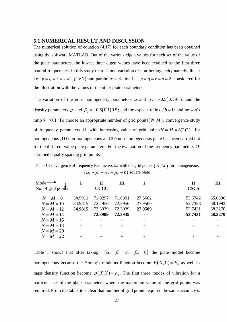
5.1.NUMERICAL RESULT AND DISCUSSION The numerical solution of equation (4.17) for each boundary condition has been obtained
using the software MATLAB. Out of the various eigen values for each set of the value of
the plate parameters, the lowest three eigen values have been retained as the first three
natural frequencies. In this study there is one variation of non-homogeneity namely, linear
i.e. 1p q r s (LVN) and parabolic variation i.e. 2p q r s considered for
the illustration with the values of the other plate parameters .
The variation of the non- homogeneity parameters 1 and 2 0.5 0.1 0.5 ; and the
density parameters 1 and 2 0.5 0.1 0.5 ; and the aspects ratio / 1a b ; and poison’s
ratio 0.3 . To choose an appropriate number of grid points ,N M , convergence study
of frequency parameters with increasing value of grid points 8(2)22N M , for
homogeneous ,1D non-homogeneous and 2D non-homogeneous plate has been carried out
for the different value plate parameters. For the evaluation of the frequency parameters
assumed equally spacing grid points.
Table 1 Convergence of frequency Parameters with the grid points ,N M for homogeneous
1 1 2 2 0 square plate
Table 1 shows that after taking 1 1 2 2 0 the plate model become
homogeneous because the Young’s modulus function become 0,E X Y E as well as
mass density function become 0,X Y . The first three modes of vibration for a
particular set of the plate parameters where the maximum value of the grid points was
required. From the table, it is clear that number of grid points required the same accuracy is
Mode
No. of grid points
I II III I II III
CCCC CSCS
8N M 34.9911 71.0297 71.0301 27.5662 53.6742 65.0396
10N M 34.9815 72.2956 72.2956 27.9560 52.7323 68.1993
12N M 34.9815 72.3939 72.3939 27.9509 53.7431 68.3270
14N M - 72.3989 72.3939 - 53.7431 68.3270
16N M - - - - - -
18N M - - - - - -
20N M - - - - - -
22N M - - - - - -
28
in the order of the nature of the plate. It is found that for the same set of the values of the
other plate parameters the frequency parameters for the CCCC edge is higher than CSCS
edge for each and every mode.
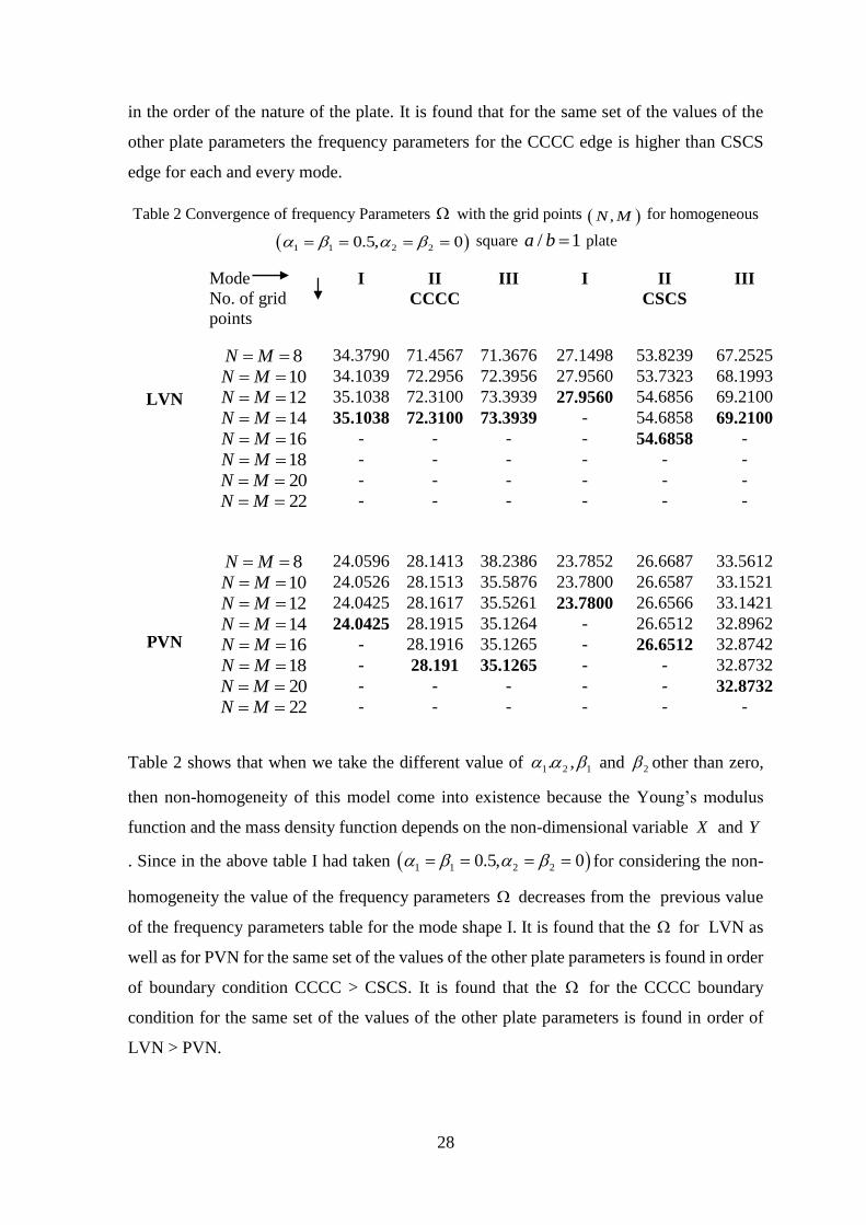
Table 2 Convergence of frequency Parameters with the grid points ,N M for homogeneous
1 1 2 20.5, 0 square / 1a b plate
Table 2 shows that when we take the different value of 1 2 1. , and 2 other than zero,
then non-homogeneity of this model come into existence because the Young’s modulus
function and the mass density function depends on the non-dimensional variable X and Y
. Since in the above table I had taken 1 1 2 20.5, 0 for considering the non-
homogeneity the value of the frequency parameters decreases from the previous value
of the frequency parameters table for the mode shape I. It is found that the for LVN as
well as for PVN for the same set of the values of the other plate parameters is found in order
of boundary condition CCCC > CSCS. It is found that the for the CCCC boundary
condition for the same set of the values of the other plate parameters is found in order of
LVN > PVN.
LVN
Mode
No. of grid
points
I II III I II III
CCCC CSCS
8N M 34.3790 71.4567 71.3676 27.1498 53.8239 67.2525
10N M 34.1039 72.2956 72.3956 27.9560 53.7323 68.1993
12N M 35.1038 72.3100 73.3939 27.9560 54.6856 69.2100
14N M 35.1038 72.3100 73.3939 - 54.6858 69.2100
16N M - - - - 54.6858 -
18N M - - - - - -
20N M - - - - - -
22N M - - - - - -
PVN
8N M 24.0596 28.1413 38.2386 23.7852 26.6687 33.5612
10N M 24.0526 28.1513 35.5876 23.7800 26.6587 33.1521
12N M 24.0425 28.1617 35.5261 23.7800 26.6566 33.1421
14N M 24.0425 28.1915 35.1264 - 26.6512 32.8962
16N M - 28.1916 35.1265 - 26.6512 32.8742
18N M - 28.191 35.1265 - - 32.8732
20N M - - - - - 32.8732
22N M - - - - - -

29
Table 3 Convergence of frequency Parameters with the grid points ,N M for homogeneous
1 1 2 2 0.5 square / 1a b plate
Table 3 shows that when we take the different value of 1 2 1. , and 2 other than zero,
then non-homogeneity of this model come into existence because the Young’s modulus
function and the mass density function depends on the non-dimensional variable X and Y
.Since in the above table I had taken 1 1 2 2 0.5 for considering the non-
homogeneity the value of the frequency parameters decreases from the previous value
of the frequency parameters table for the mode shape I. It is found that the for LVN as
well as for PVN, for the same set of the values of the other plate parameters is found in
order of boundary condition CCCC > CSCS. It is found that the for the CCCC boundary
condition for the same set of the values of the other plate parameters is found in order of
PVN > LVN.
LVN
Mode
No. of grid
points
I II III I II III
CCCC CSCS
8N M 35.9958 72.8952 72.3676 28.9952 54.9853 68.5231
10N M 35.9526 72.7625 72.3256 28.9862 54.9762 68.6542
12N M 35.9214 72.2156 72.3210 28.9861 54.9642 69.5362
14N M 35.9214 72.2156 72.3210 28.9861 54.8942 69.2489
16N M - - - - 54.8942 69.2489
18N M - - - - - -
20N M - - - - - -
22N M - - - - - -
PVN
8N M 36.6214 73.5082 73.5216 29.4098 55.4362 69.1398
10N M 36.5642 73.4521 74.1520 29.4087 55.9030 69.9421
12N M 36.5542 74.0920 74.1463 29.4092 55.1107 69.9511
14N M 36.5542 74.0920 74.1205 29.4044 55.1102 69.5111
16N M - - 74.1205 29.4044 55.1101 -
18N M - - - - 55.1101 -
20N M - - - - - -
22N M - - - - - -

30
Figure 9 Frequency parameters versus non-homogeneity parameters 1 for a square CCCC
plate for 1 2 0.5 , for the first, second and third mode respectively
Figure 10 Frequency parameters versus non-homogeneity parameters 1 for a square CSCS
plate for 1 2 0.5 , for the first, second and third mode respectively
31
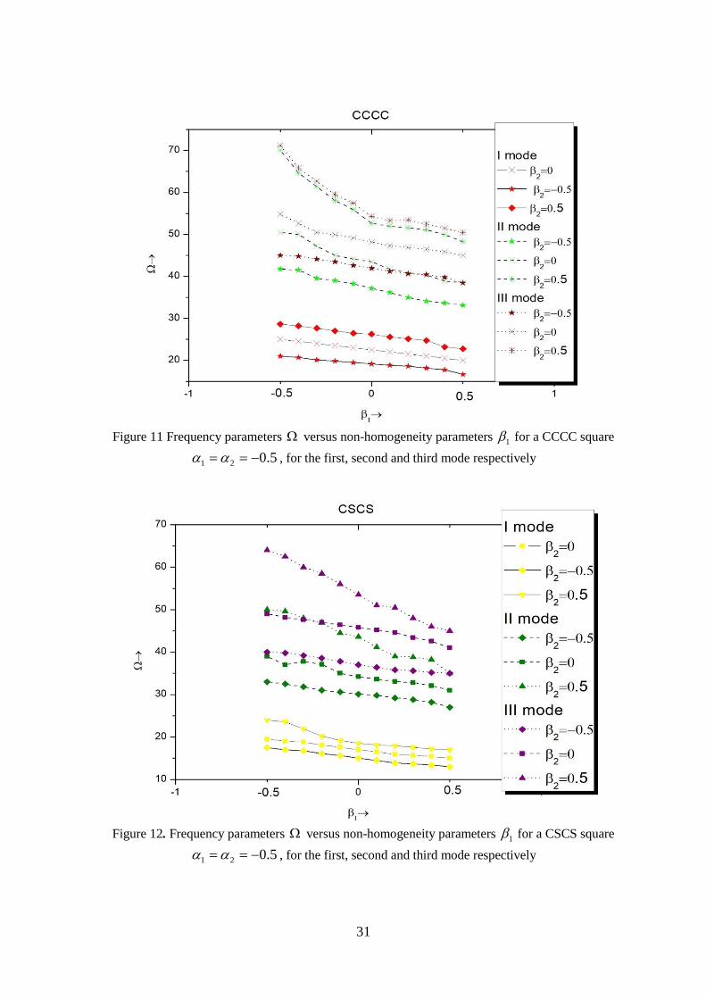
Figure 11 Frequency parameters versus non-homogeneity parameters 1 for a CCCC square
1 2 0.5 , for the first, second and third mode respectively
Figure 12. Frequency parameters versus non-homogeneity parameters 1 for a CSCS square
1 2 0.5 , for the first, second and third mode respectively

32
Figure 9 and 10 shows the graphs for the frequency parameters versus non homogeneity
parameters 1 for the square plate with the fixed value of 1 2 0.5 and three different
values of 2 0.5,0,0.5 for the first three mode of vibration for the two different
boundary condition. It is found that the frequency parameters increases as the stiffness
of the plate along X-direction (i.e. 1 ) increases whatever the value of the 2 . It further
shows that frequency parameters increases with stiffness of the plate along Y-direction
(i.e. 2 ) changes from -0.5 to 0.5.The rate of increase of frequency parameters with 1
increases with increasing the number of modes for the given boundary conditions CCCC >
CSCS for the same set of the values of the other parameters. The effect of the 2 on the
frequency parameters is more pronounced for 1 = -0.5 as compared to 1 =0.5.
Figure 11 and 12 shows that Frequency parameters versus non-homogeneity parameters
1 for a square 1 2 0.5 , for the first, second and third mode respectively. The
frequency parameters decreases as the value of density parameters 1 increases i.e. plate
density becomes higher along X-direction whatever the value of 2 for the both the
boundary condition. Also the frequency parameters decreases due to increasing the value of
2 . It means the plate also become denser in Y- direction by increasing the value of 2 . The
rate of decreasing the value of with 1 is higher in CCCC plate boundary condition as
compare to CSCS plate boundary condition for the same set of the values of the other plate
parameters.

33
Figure 13 frequency parameters versus aspect ratio for CCCC plate
Figure 14 frequency parameters versus aspect ratio for CSCS plate

34
Figure 13 and 14 shows the behaviour of the aspect ratio on the frequency parameters
for 1 2 0.5 , 1 2 0.5 for the two different boundary condition CCCC and
CSCS plate for the first three mode of vibration. The graph for 1 2 1 2 0.5
has not be shown in the figure because it was overlapping with each other graphs. From the
figure it has clear shown that the frequency parameters increases with the increasing of
the aspects ratio for all the three modes of vibration. When the value of becomes large
for these boundary condition the plate behaves like a beam of length a , C/S at both the ends
undergoes the anticlastic bending. Due to which the frequency parameters increases. The
effect is more prolonged when 1 and in the order of the boundary condition CCCC >
CSCS for the same set of the values of other plate parameters. And this effect also increases
with increase in the number of modes.
5.1.4. Mode Shape
Boundary
condition
Mode shape
CCCC CSCS
I
II
III
Figure 15 Mode shape

35
Figure 15 shows various modes of vibration a) CCCC and b) CSCS for
1 2 1 2 0.5 and 1 .

36
Chapter 6
CONCLUSION

37
6.1. Conclusion The variation of the non-homogeneity of the plate material on the vibration characteristics
of the rectangular plates has been analysed using the FDM technique method. For
illustration the numerical result for linear variation for the non –homogeneity have been
obtained for the first three modes of the vibration for the two different boundary condition
CCCC and CSCS.
6.1.1 Observation
The following observation has been made:
(i) With the increase of non-homogeneity parameters of the plate, the non-dimensional
frequency parameters increase when the density parameters of that plate material
remain constant.
(ii) When the Young’s modulus parameters kept constant, non-dimensional frequency
parameters decreases with increasing of the density parameters.
(iii) For the both boundary condition non-dimensional frequency parameters increase
with increase the value of aspects ratio when the other parameters of the plate
remain constant.
(iv) When there is no change in the other parameters of the plate the non- dimensional
frequency parameters for the PVN is smaller as compared to LVN in non-
homogeneity, when the plate density higher toward the edge 0X and 0Y as
compared to 1X and 1Y .When the change in order of density of the plate the
results become the vice versa.
(v) When there is no change in the density parameters the value of the non-dimensional
frequency parameters is higher for PVN as compared to LVN because, the plate is
more stiff towards the edges 0X and 0Y as compared to the 1X and 1Y
. The results will be vice versa when the order of the stiffness changes from previous
case.
6.1.2. Future Work
The above analysis is useful in the field of electronics and aerospace industry. Due to its
non-homogeneity this paper can also give some idea in the field of metallurgy. This type of
the non-homogeneity arises during the fiber reinforced plastic structure and in composite
structure, which use fibers of different strength properties along two mutually perpendicular
directions along the edge of the plate.

38
REFERENCES

39
References
1. Bardell NS (1991) Free vibration analysis of a flat plate using the hierarchical finite element
method. Journal of Sound and Vibration 151: 263–289.
2. Bert CW, Jang SK and Striz AW (1988) Two new approximate methods for analysing free
vibration of structural components. AIAA Journal 26: 612–618.
3. Bhat RB, Laura PAA, Gutierrez RG and Cortinez VH (1990) Numerical experiment on the
determination of natural frequencies of transverse vibrations of rectangular plates of non-uniform
thickness. Journal of Sound and Vibration 139: 205–219.
4. Das AK and Mishra DM (1971) Free vibrations of an isotropic nonhomogeneous circular plate.
AIAA Journal 9:963–964.
5. Gupta AK, Saini M, Singh S and Kumar R (2012) Forced vibrations of non-homogeneous
rectangular plate of linearly varying thickness. Journal of Vibration and Control 1–9.
6. Gupta US, Lal R and Sharma S (2007) Vibration of non- homogeneous circular plates with
variable thick- ness. Journal of Sound and Vibration 302(1–2): 1–17
7. Huang M, Ma XQ, Sakiyama T, Matsuda H and Morita C (2007) Free vibration analysis of
rectangular plates with variable thickness and point support. Journal of Sound and Vibration 300:
435–452.
8. Jin GY, Su Z, Shi SX, Ye TG and Gao SA (2014b) Three- dimensional exact solution for the free
vibration of arbitrarily thick functionally graded rectangular plates with general boundary
conditions. Composite Structures 108:565–577.
9. Kerboua Y, Lakis AA, Thomas M and Marcouiller L (2007) Hybrid method for vibration
analysis of rectangular plates. Nuclear Engineering Design 237: 791–801.
10. Lal R and Dhanpati (2007) Transverse vibrations of non- homogeneous orthotropic rectangular
plates of variable thickness: A spline technique. Journal of Sound and Vibration 306: 203–
214.
11. Lal R and Kumar Y (2012a) Boundary characteristic orthogonal polynomials in the study of
transverse vibrations of non-homogeneous rectangular plates with bilinear thickness variation.
Shock and Vibration 19: 349–364.
12. Lal R and Saini R (2015) Buckling and vibration analysis of non-homogeneous rectangular
Kirchhoff plates resting on two-parameter foundation. Meccanica 50: 893–913.
13. Leissa AW (1973) Free vibrations of rectangular plates. Journal of Sound and Vibration
31: 257–293.
14. Olszak W (1958) Non-homogeneity in elasticity and plasticity. Poland: Pergamon press.
15. Ramkumar RL, Chen PC and Sanders WJ (1987) Free vibration solution for clamped
orthotropic plates using Lagrangian multiplier technique. AIAA Journal 25:146–151.
16. Shu C and Richards BE (1992) Application of generalized differential quadrature to solve two
dimensional incompressible Naiver-Stokes equations. International Journal of Numerical Methods
in Fluids 15: 791–798.
40
17. Shu C (2000) Differential Quadrature and Its Application in Engineering. London: Springer
Verlag.
18. Tomar JS, Gupta DC and Jain NC (1982a) Axisymmetric vibrations of an isotropic non-
homogenous circular plate of linearly varying thickness. Journal of Sound and Vibration 85:
365–370.
19.Tomar JS, Gupta DC and Jain NC (1984) Free vibrations of an isotropic non-homogeneous
infinite plate of parabolic- ally varying thickness. Indian Journal of Pure Applied Mathematics
15: 211–220.
20. Sakata T, Takahashi K and Bhat RB (1996) Natural frequencies of orthotropic rectangular plates
obtained by iterative reduction of the partial differential equation. Journal of Sound and Vibration
189: 89–101.
21. Huang M, Ma XQ, Sakiyama T, Matsuda H and Morita C (2007) Free vibration analysis of
rectangular plates with variable thickness and point support. Journal of Sound and Vibration 300:
435–452.
22. Kerboua Y, Lakis AA, Thomas M and Marcouiller L (2007) Hybrid method for vibration
analysis of rectangular plates. Nuclear Engineering Design 237: 791–801.
23. Bhaskar K and Sivaram A (2008) Un-truncated infinite series superposition method for
accurate flexural analysis of isotropic/orthotropic rectangular plates with arbitrary edge conditions.
Composite Structures 83: 83–92.
24. Shi J, Chen W and Wang C (2009) Free vibration analysis of arbitrary shaped plates by boundary
knot method. Acta Mechanica Solida Sinica 22: 328–336.
25. Shu C and Richards BE (1992) Application of generalized differential quadrature to solve two-
dimensional incompressible Naiver-Stokes equations. International Journal of Numerical Methods
in Fluids 15: 791–798.
26. Striz AG, Wang X and Bert CW (1995) Harmonic differential quadrature method and
applications to analysis of structural components. Acta Mechanica 111: 85–94.
27. Shu C and Chew YT (1997) Fourier expansion-based differential quadrature and its application
to Helmholtz eigenvalue problems. Communications Numerical Methods in Engineering 13: 643–
653.
28. Liu GR and Wu TY (2001) Vibration analysis of beams using the generalized differential
quadrature rule and domain decomposition. Journal of Sound and Vibration 246: 461–481.
29. K.S Virdi (2006) Finite difference method for nonlinear analysis of structures.
30. Chakraverty S, Jindal R and Agarwal VK (2005) Flexural vibration of non-homogeneous elliptic
plates. Indian Journal of Engineering & Materials Sciences 12: 521–528.
31. Gutierrez RH, Laura PAA, Bambill DV, Jederlinic VA and Hodges DH (1998) Axisymmetric
vibrations of solid circular and annular membranes with continuously varying density. Journal of
Sound and Vibration 212(4): 611–622.
32. Dipak Kr. Maiti & P. K. Sinha. Bending and free vibration analysis of shear deformable
laminated composite beams by finite element method. Composite Structures, 29 (1994): 421- 431.
41
32. Najafov AM, Sofiyev AH and Kuruoglu N (2014) Vibration analysis of nonhomogeneous
orthotropic cylindrical shells including combined effect of shear deformation and rotary inertia.
Meccanica 49: 2491–2502.
33. Tornabene F, Fantuzzi N, Viola E and Carrera E (2014) Static analysis of doubly-curved
anisotropic shells and panels using CUF approach, differential geometry and differential quadrature
method. Composite Structures 107: 675–697.
34. Sofiyev AH (2014) The influence of non-homogeneity on the frequency-amplitude
characteristics of laminated orthotropic truncated conical shell. Composite Structures 107:334–345.
35. Jones RM (1999) Mechanics of composite materials, 2nd edn. Philadelphia: Taylor & Francis.