Embed Size (px)
Citation preview

Powder Metallurgy Progress, Vol.8 (2008), No 2 59
FRACTOGRAPHY OF SINTERED IRON AND STEELS
E. Dudrová, M. Kabátová
Abstract The processing technology of sintered steels cannot avoid typical microstructural discontinuities such as pores and their agglomerates and prior particle, interface and interphase boundaries, which all influence initiation, growth, and propagation of cracks when the sintered microstructure is mechanically loaded. Fracture paths and fracture resistance are shown to be related to details of the complex, frequently inhomogeneous, microstructures comprising, ferrite, austenite, upper and lower bainite, martensite, pores and weak interfaces. All these have characteristic fracture resistance properties resulting in, frequently combinations of, dimple rupture, cleavage, intergranular and interparticle failure micromechanisms. Keywords: fracture in metals, fractography of sintered iron and steels
INTRODUCTION Metals fail in many different ways and for different reasons. The main purpose of
microfractography is to determine how and why a component fails - it means to determine a mode of failure and, together with other information, to determine the causes of failure and to determine the conditions for avoiding a similar failure in the future. One of the most important sources of information relating to the cause of failure is the morphology of fracture surface.
This communication will strive to present the basic micro-fractographic data relevant to principal fracture modes in engineering wrought and porous materials with particular focus on microfractography of sintered iron and steels.
Microfractography of engineering materials The failure of a loaded part represents a final stage of mechanical loading and
processes of gradual damage up to failure depend on the loading mode, microstructure, temperature and environmental conditions [1]. Usually, the failure in metals is classified according to loading mode (overload, fatigue, creep), energy consumption (tough – with high energy consumption - and brittle - with low energy consumption) and fracture mechanisms (brittle – non-plastic failure and ductile - plastic failure).
For engineering materials there are only two possible modes of fracture, ductile and brittle. Macroscopic examinations enable to identify a fracture mode which can be classified as ductile or brittle, Fig.1a,b [2]. The main difference between ductile and brittle fracture is attributed to the amount of plastic deformation before the failure. Ductile materials exhibit extensive plastic deformation with necking; the absence of deformation indicates a brittle failure (non-plastic failure).
Eva Dudrová, Margita Kabátová, Institute of Materials Research, Slovak Academy of Sciences, Košice, Slovak Republic

Powder Metallurgy Progress, Vol.8 (2008), No 2 60
Fig.1a. Failure classified by ductile fracture
mode; features: development of plastic deformation before failure; ductile failure consumes more energy than brittle failure.
Fig.1b. Failure classified by brittle fracture mode; features: failure in non-plastic mode;
rapid crack propagation; low energy consumption.
The microfractography of the fracture surface by SEM allows to analyze the exact ductile and brittle failure modes on micro-level as following - ductile fractures (under tensile, shear and bending overload), brittle intergranular fracture mechanism (stress corrosion cracking, liquid metal embrittlement, creep, grain-boundary embrittlement) and brittle transgranular mechanism (cleavage, stress corrosion cracking, fatigue). In general, there are three basic crack growth mechanisms possible in force overload fracture: brittle intergranular, when the crack follows a path along grain boundaries, brittle transgranular, when the crack propagates through grains via cleavage, and ductile transgranular, when the crack propagates through grains via microvoid coalescence.
Regardless of the fracture paths, there are essentially only four principal fracture modes: dimple rupture, decohesion rupture, cleavage, fatigue.
Dimple Rupture Dimple Rupture (Microvoid Coalescence or Ductile Dimples) includes microvoid
nucleation, growth and coalescence. It is the typical failure mode of most common structural alloys when overload is the principle cause of fracture. The microvoids nucleate at relocalized strain discontinuities such as those associated with a-priori defects (pores, microcracks), second phase particles, inclusions, grain boundaries, dislocations pile-up. As the strain increases the microvoids grow, coalesce and eventually form a continuous fracture surface; crack extension in ductile fractures involves plastic deformation.
(a) (b)
Fig.2. Transgranular (a) and intergranular (b) ductile dimple fracture.

Powder Metallurgy Progress, Vol.8 (2008), No 2 61
(a) (b) (c)
Fig.3. Equiaxed dimples formed by microvoid coalescence under the conditions of uniaxial tensile load (a); elongated dimples formed in the tear and shear conditions (b);
shallow dimples formed at low plastic deformation, copyright from [1] (c).
When microvoids nucleate inside the grains then the fracture mode is Transgranular Dimple Rupture, Fig.2a; when microvoids nucleate at the grain boundaries the fracture mode is Intergranular Dimple Rupture, Fig.2b. The shape of dimples - equiaxed, elongated, shallow, Fig.3a,b,c, - is governed by the state of stress within the material as the microvoids form, grow and coalesce.
Decohesive Rupture Decohesive Rupture (Brittle Intergranular Fracture or Grain Boundary Separation)
is associated almost exclusively with rupture along grain boundaries and arises at marked differences between the properties of grain boundaries and matrix (grain boundary embrittlement by thermally activated segregation, impurities at the grain boundaries, formation of precipitates or a continuous film along the boundaries). The morphology of intergranular fracture facets depends on the cause of the failure; the facets can be smooth or rough, Fig.4a,b.
(a) (b)
Fig.4. Morphology of the decohesive rupture (intergranular failure) facets depends on the cause of the decohesive failure; intergranular facets can be smooth (a), or rough (b).
Cleavage Cleavage is a low energy fracture that propagates along well-defined low-index
crystallographic planes known as cleavage planes, {100} for BCC and base plane (0001)
Powder Metallurgy Progress, Vol.8 (2008), No 2 62 for HCP crystals. Cleavage failure mode arises when slip processes cannot take place, when dislocation movement is impossible on slip planes or when it is heavily blocked (at conditions of triaxial stress, at high deformation rate, in highly strengthened microstructures, at low temperature test conditions). The microstructure of engineering alloys contains grain and subgrain boundaries, inclusions, dislocations and other imperfections that produce distinct cleavage fracture surface features, such as cleavage steps, river patterns, tongues and feather markings, as well. The network of cleavage steps is known as river patterns, Fig.5a; tongues, Fig.5b, result from cleavage across microtwins located near the crack tip.
Transgranular quasi-cleavage Transgranular quasi-cleavage arises when the cleavage growth is re-initiated by
intensive plastic deformation, Fig.6. It occurs in high-strength quench-hardenable steels; precipitation conditions that inhibit plastic deformation promote cleavage.
(a) (b)
Fig.5. River patterns (a) [3], tongues (b) [3]. Fig.6. Quasi cleavage.
Fatigue Fatigue is defined as the progressive localized permanent structural change that
occurs in the material subjected to repeated or fluctuating strains at stresses having a maximum value less than the strength of the material. Fatigue failure - at least in case of high cycle fatigue – is characterized by the absence of macroplastic deformation of a failed component, also in the case of ductile materials which under monotonic loading exhibit a high plastic deformation. Fatigue is a time-dependent mechanism being separated into three stages: Stage I (crack initiation - usually at or near the surface where the cyclic strain is greatest); Stage II (stable crack growth with features known as fatigue striations, which relate to the direction of crack propagation), Stage III (unstable fast fracture related to the failure by overload - brittle or ductile modes).
Microstructural constituents and fracture mode The crystal structures of basic constituents in steels are bcc (ferrite, martensite) or
fcc (austenite). At single force overloading and at conditions enabling a sufficiently high mobility of dislocations the microstructural components fail in the following modes: - polycrystalline ferrite fractures in the ductile dimple mode (under the conditions when mobility of dislocations is heavily blocked the ferrite can fail in transgranular cleavage mode); - lamellar pearlite, in dependence on local stress directions, can fracture by cleavage, or by separations along cementite lamellas, ferrite in pearlite can also fail in

Powder Metallurgy Progress, Vol.8 (2008), No 2 63 ductile mode with dimples (initiated by cementite lamellas) having an equiaxed or “canal” shape; - ferrite-carbide microstructures (bainite, sorbite) fail in transgranular ductile mode with fine dimples initiated by carbides; - low-carbon martensite having a sufficient mobility of dislocations can fracture in transgranular ductile dimple mode; - medium carbon and high-carbon martensite, due to high barriers for dislocations mobility, fail in transgranular cleavage.
In principle, the fracture surface morphology is determined by the locally operating fracture micromechanism. This can change in relation to the microstructural composition, local state of stress and actual test conditions (loading rate, temperature). Despite the mostly complex microstructure of steels, the sequence of individual operating fracture micro-mechanisms exhibits specific “time-local order” governed by principles of fracture mechanics: - intergranular fracture, - transgranular cleavage, - intergranular ductile, - transgranular ductile.
FRACTOGRAPHY OF SINTERED IRON AND STEELS Considerable information in the area of fracture behaviour of sintered iron under
monotonic and cyclic loading was reported up to now, e.g. by Exner and Pohl [4], Šlesár, Dudrová et al.[5-8], Pelikán [9], as well as by Danninger, Weiss and Stickler, particularly for high cycle fatigue, e.g. [10-14], by Moon [15,16] and Bergmark [17].
Generally, the fracture of sintered steels follows the behaviour of wrought steels, with the following significant additional factors: the presence of pores and remnants of original particle surfaces, as well as generally more complex and heterogeneous microstructures. In the case of Ni-Cu-Mo-C diffusion alloyed sintered steels, the microstructures generally consist of pearlite, bainite, martensite, as well as ferrite and austenite. More homogeneous microstructures can be obtained using prealloyed powders (e.g. Fe-Mo, Fe-Cr-Mo). Cu alloyed sintered steels have precipitation strengthened microstructures consisting of the ferrite + ε phase, while the microstructure of phosphorus alloyed steels comprises solid solution strengthened ferrite. Pores appear as interconnected or isolated; at low density, when interconnected porosity is present, plastic strains are concentrated at particle necks that are much smaller in diameter than the original powder particles. During the loading these particle necks can deform much more extensively than the material of the particle volume. This process results in a high local plastic flow but in a low (macroscopic) elongation to fracture of a loaded body (see Fig.9a-d). Thus the resulting fracture is macroscopically brittle and microscopically ductile (with dimple formation).
The original powder particle surfaces may be contaminated by oxides, nitrides, or other impurities. Their presence can give rise to deterioration of interfaces between the adjacent particles; i.e. nucleating the first microcracks, as well as providing easy paths for crack growth and crack propagation. For high-density sintered steels isolated pores are dominant, which act as stress concentrators; the degree of the local strain increases depending on pore geometry, distance between the pores and local stress directions and their interactions with matrix microstructures surrounding the pores, e.g. [15,16,18-20].
Crack Nucleation and Crack Growth Pores in sintered microstructure act as stress-concentrators and give rise to local
increase of strains near the pores. The degree of the local strain increase depends on the pore geometry, distance between the pores, as well as on local stress directions and their interactions. The crack initiation and crack propagation is controlled by the strength and plasticity of structures surrounding the pores.

Powder Metallurgy Progress, Vol.8 (2008), No 2 64
In the case of dominantly interconnected pores the failure is controlled by the loss of plastic stability on the level of interparticle necks. Due to the usually small size of particle necks they are loaded in conditions near to plane stress state. It has been suggested that crack initiation and crack propagation for dominantly isolated pores is controlled by strength and plasticity of structures surrounding the pores, e.g. [15,16,20,21]. According to Moon [15], mechanical interactions between the pores and surrounding stressed matrix can be modelled by the use of the stress intensity factor, K = ψσ(πa)1/2 (where “a” designates the defect size), ψ is a geometric factor and the plastic zone size is r ~ (1/2π)·(K/σy)2. If the yield strength, σy, of the matrix material is low, the plastic zone size can cover a larger matrix volume near the pore. The plastic deformation in this area can develop intensively. If the yield strength of the material is high, the plastic zone is small and constrained within an envelope of unyielded matrix areas. In such area the plastic deformation cannot develop. When the stress intensity factor reaches a critical value, K1C, the propagation of the crack occurs in the zone of constrained plasticity. A phenomenological model of the relationship between the fracture toughness, failure mechanisms and strength of the matrix for sintered steels has been presented [22]. It postulates the dependence of fracture toughness on the yield stress in areas with high porosity and that then the processes of plastic deformation and fracture are concentrated in the interparticle contacts, i.e. the sinter necks. In high density areas, K1C does not change; the failure mode is critically controlled by the material strength, so an increase of the yield strength results in a decrease of the critical defect size.
The high number of potential sites for crack nucleation (pores, their agglomerates, interfaces such as original particle surfaces) and different directions of micro stress-strain processes following from alteration of different structural constituents results in a “selective” character of micro-cracks growth and propagation.
Crack nucleation is associated with local microscopic defects and local stresses. Favoured nucleation sites include weak interfaces associated with contaminations, pores and their agglomerates. Crack growth results from the interaction and joining up of adjacent growing microcrack systems. Especially in the early stages of the failure process the responses of the different local microstructures to stress and microcrack presence are different [stop, deflect, propagate] and these have to be considered.
Fractography of sintered iron
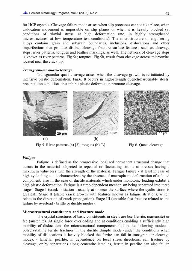
Compaction facets Metal powder represents a statistical set of particles with different geometry and
mechanical properties. During compaction the particles deform, leading to formation of solid interfaces at the point or planar particle contacts (compaction facets), Fig.7, that represent areas with elevated free energy and thus become potential areas for nucleation and growth of inter-particle necks during sintering.
Powder Metallurgy Progress, Vol.8 (2008), No 2 65
(a) (b) (c)
Fig.7. Effect of pressure on formation of compaction facets; prealloyed powder Fe-2Ni-0.5Mo, compacting pressure 100 MPa (a), 400 MPa (b), 800 MPa (c).
Effect of sintering conditions on morphology of particle necks and fracture facets The powder compact containing a large amount of free energy is converted into a more
stable state during sintering. The main sintering mechanisms leading to particle necks formation are surface diffusion, grain boundary and volume diffusion, respectively. Mixtures of chemically dissimilar compositions tend to convert towards an equilibrium uniform state, as required by the phase diagram.
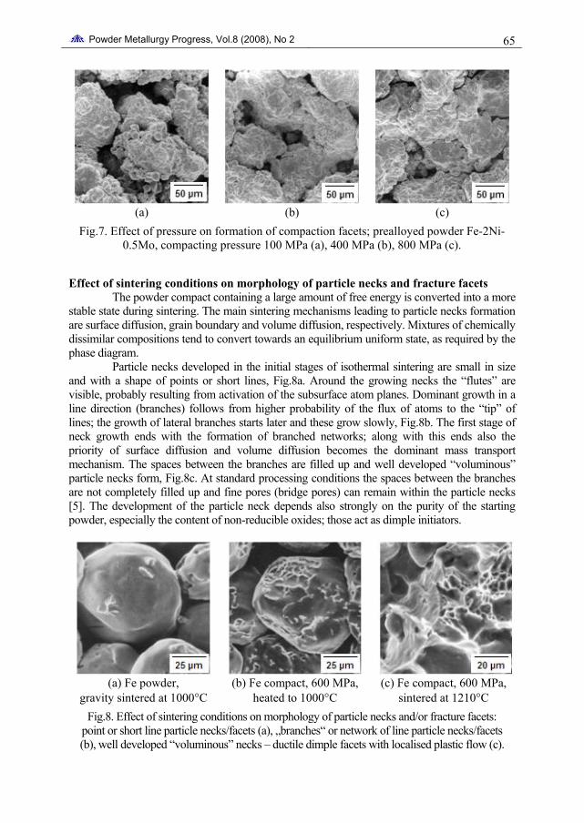
Particle necks developed in the initial stages of isothermal sintering are small in size and with a shape of points or short lines, Fig.8a. Around the growing necks the “flutes” are visible, probably resulting from activation of the subsurface atom planes. Dominant growth in a line direction (branches) follows from higher probability of the flux of atoms to the “tip” of lines; the growth of lateral branches starts later and these grow slowly, Fig.8b. The first stage of neck growth ends with the formation of branched networks; along with this ends also the priority of surface diffusion and volume diffusion becomes the dominant mass transport mechanism. The spaces between the branches are filled up and well developed “voluminous” particle necks form, Fig.8c. At standard processing conditions the spaces between the branches are not completely filled up and fine pores (bridge pores) can remain within the particle necks [5]. The development of the particle neck depends also strongly on the purity of the starting powder, especially the content of non-reducible oxides; those act as dimple initiators.
(a) Fe powder,
gravity sintered at 1000°C (b) Fe compact, 600 MPa,
heated to 1000°C (c) Fe compact, 600 MPa,
sintered at 1210°C Fig.8. Effect of sintering conditions on morphology of particle necks and/or fracture facets:
point or short line particle necks/facets (a), „branches“ or network of line particle necks/facets (b), well developed “voluminous” necks – ductile dimple facets with localised plastic flow (c).

Powder Metallurgy Progress, Vol.8 (2008), No 2 66
The mechanical behaviour of porous metals and consequently the fracture facets are governed by effective material microvolumes transferring an applied external load, Fig.9a-d. When interconnected porosity with small particle necks dominates, the particle necks act as critical micro-volumes. The stress concentration at particle necks promotes the dislocation movement with following annihilation at free surfaces [5]. It results in the formation of slip steps. The smaller the particle neck is the higher is a localised plastic flow; and the lower is the total deformation of the loaded system, Fig.10 [9]. It represents the fundamentals of the effect of porosity (size of particle necks) on the strain to fracture [5,9]. The higher the porosity is (smaller necks) the lower is the tensile strain of sintered metals; the higher the matrix strength the lower is the strain to fracture, Fig.11.
(a) (b) (c) (d)
Fig.9. Mechanical behaviour of porous metal formed by a set of small “bars” at tensile stress (a) with geometry of particle necks defined by parameter „m“ [9] (b); the stress concentrated at particle neck promotes dislocation movement with annihilation at free
surface/pore surface [5] (c) leading to local plastic flow development (d).
Fig.10. Local plastic flow (at the necks) v.s. total strain to fracture for the various values of m = M/R (M and R are the thickness and
radius of the particle neck) [9].
Fig.11. Effect of density (porosity) of sintered iron on tensile stress-strain
diagram [23].
Effect of porosity and failure conditions Basic types of fracture facets in sintered iron, Fig.12a-f and Fig.13a,b,c, are
controlled by porosity (related to geometry and properties of particle necks), microstructure

Powder Metallurgy Progress, Vol.8 (2008), No 2 67 and conditions of failure, particularly of strain rate, temperature and loading mode (tensile, bending, fatigue).
(a) interparticle ductile dimple
failure Fe, P>10%
(b) trans- and interparticle ductile dimple failure
Fe, P~10%
(c) transgranular ductile dimple failure Fe, P<5%, r.t.
(d) transgranular cleavage and
some ductile dimple Fe compact, P>10%, impact test at -196°C
(e) transgranular cleavage Fe compact, P<5%,
impact test at -196°C
(f) intergranular decohesion - sintering in technical argon
Fe compact, P~5%, impact test at RT
Fig.12. Elementary types of fracture facets in sintered iron - effect of processing and testing conditions ( d –Fe with P>10% fractures at -196ºC in mixed cleavage and ductile failure where ductile dimples correspond to failure of the necks with the size less than ~5
µm, due to the low barriers for dislocation moving [5, 11].
(a) (b) (c)
Fig.13. Fatigue failure in sintered iron [24]: (a) ductile dimple failure, 170 MPa, 4·103 cycles, (b) mixed striation – dimple failure, 4·103 cycles, (c) ductile fatigue striation, 90
MPa, 1·106 cycles.

Powder Metallurgy Progress, Vol.8 (2008), No 2 68
A lot of investigation into fracture behaviour of sintered iron and steels under monotonic and especially in fatigue loading was reported by Danninger et al., e.g. in the Refs. [10-14].
Fractography of sintered steels Light and scanning electron microscopic observations relating to initiation,
growth, joining, fracture paths and fracture resistance are presented here for sintered steels based on prealloyed (Astaloy CrL), diffusion alloyed (Astaloy AE) and mixed (Fe-P-[Cu]-C, Fe-Cu-C) powders. The „cracking“ phenomena related to details of frequently complex and inhomogeneous microstructures comprising, ferrite, austenite, upper and lower bainite, martensite, pores and weak interfaces are shown. All these studied cases have characteristic fracture resistance properties resulting in, frequently combinations of dimple rupture, cleavage, interparticle and intergranular failure micromechanisms.
Distaloy AE + 0.5/0.7%C In the case of Ni-Cu-Mo diffusion alloyed sintered steels the microstructures
generally consist of pearlite, bainite, martensite, as well as ferrite and austenite. Microscopic observations, Figs.14a-c, of tensile specimens of sintered Distaloy AE+0.7%C loaded to ~23%, ~80% and ~90% of the fracture stress illustrate the initiation and growth of the failure process. As in fatigue, there are thus three stages of the fracture process: crack nucleation, crack growth and crack propagation, with their different criteria. Additionally, final failure can result from the interaction and joining up of adjacent microcrack tips. Crack nucleation is probably governed by critical distortional strain energy [25], whereas for crack propagation it is the total strain energy. Especially in the early stages of the failure process the responses of the different local microstructures to presence of stress and microcracks are different [stop, deflect, propagate] and these need to be considered.
(a) (b) (c)
Fig.14. Microscopic observations of the failure process in a tensile specimen of sintered Distaloy AE + 0.7% C steel - (a): initiation of cracks at a stress level corresponding to
~23% of the fracture stress (b): microstructure-controlled crack growth at ~80% and (c): at ~90% of the fracture stress.
Figure 15 shows the heterogeneous microstructure of Distaloy AE+0.5%C steel sintered at 1120°C for 30 minutes in an atmosphere of 10%H2+90%N2 and cooled at ~8°C/min. The micostructure consists of bainite, pearlite, martensite and austenite areas. For studying the relationship between microstructure and fracture behaviour it is very useful to analyse the relationship „crack – microstructure“, as shown in Fig.16. Also, metallographic analyses related to morphology of the fracture line enables to determine the relationship between the local

Powder Metallurgy Progress, Vol.8 (2008), No 2 69 microstructure constituents and local fracture mode, Figs.17a,b and Fig.18a,b. This method is very helpful for interpretation of fracture surface observations, Fig.17c,d and Fig.18c,d.
Fig.15.Heterogeneous microstructure of Distaloy AE (Fe-4Ni-1.6Cu-0.5Mo) + 0.5% C steel resulting from sintering at
1120°C for 30 minutes.
Fig.16. Fracture line and etched microstructure of tensile specimens
Distaloy AE + 0.5% C – cleavage in fine pearlite and bainite and ductile elongated
dimples in austenite.
(a) (b)
(c) (d)
Fig.17. The fracture line (the white layer is Ni coating of the fracture surface) of tensile specimens Distaloy AE + 0.5% C with transgranular cleavage and interface decohesion
failures (a), transgranular ductile dimple and shear failures (b) and fracture surfaces consisting of corresponding fracture facets (c,d).

Powder Metallurgy Progress, Vol.8 (2008), No 2 70
(a) (b)
(c) (d)
Fig.18. The fracture line (the white layer is Ni coating of the fracture surface) of tensile specimens from sinter hardened Distaloy AE + 0.5% C with dominant transgranular cleavage and interface decohesion failures (a,b) and fracture surfaces consisting of
corresponding fracture facets (c,d).
At the fracture line for sintered specimens Figs.17a,b, the areas of transgranular cleavage and interface decohesion failure modes can be distinguished, as well as the transgranular ductile dimple and shear modes. Similarly, at the fracture line for sintered specimens, Figs.18a,b, dominant transgranular cleavage and interface decohesion failure modes are visible. The observations enable to interpret the fracture mechanisms belonging to individual structure areas, Fig.17c,d and Fig.18c,d.
Beside the free particle surfaces the following fracture facets can be distinguished: Transgranular ductile dimple facets with fine equiaxed dimples resulting from the failure of upper bainite; interparticle ductile dimple areas with shallow equiaxed dimples resulting from the failure of the austenite areas situated near the prior particle surfaces; transgranular cleavage facets (or their sets joined by ductile steps) originated by fracture of martensite structures.
Figure 19a shows several cracks that did not participate in final fracture trajectory. Most of them arise along the residual original particle surfaces. Figure 19b shows part of the fracture surface consisting, in addition to the residual free particle surfaces, of the set of transgranular cleavage facets originated by fracture of martensite areas, then the group of dimple ductile facets (small dimples) that correspond to fractures of bainite, also, small areas of ductile fracture of pearlite (with “canal” shape of dimples), as well as of ductile failure of austenite areas (with localised plastic flow). In Figures 19c,d another part of the microstructure and the corresponding part of the fracture surface is presented. In this area

Powder Metallurgy Progress, Vol.8 (2008), No 2 71 “interparticle” ductile fracture in areas of two adjacent particles was dominant. Also, some areas of ductile dimple fracture are shown where intensive local plastic flow has occurred (probably areas of a coarse pearlite). The relatively high strength and acceptable plasticity of this steel ensues from the presence of high strength bainite and martensite structures. The possible way to increase the mechanical properties, beside an increase of the amount of bainite-martensite structures, is elimination of defects associated with original particle surfaces.
(a) (b)
(c) (d)
Fig.19. Examples of microstructure near the final fracture and corresponding fracture surfaces for sintered Distaloy AE + 0.7% C steel (a, b); Fig.19c shows the set of
transgranular cleavage facets originating in fractured martensite areas; Fig.19d shows the interparticle ductile fracture in the area of two adjacent particles.
Fe-3%Cu-0.7%C sintered steels An efficient way to increase the strength of ferrite is addition of carbon and
copper. Fe-3%Cu-0.7%C steel consists of 90% pearlite and 10% ferrite. The morphology of pearlite is influenced by the local content of Cu; Fig.20a shows the microstructure of Fe-3%Cu-0.7%C after sintering at 1180°C for 40 min and cooling at 10°C/min. Different diffusion rates of carbon and copper during sintering result in heterogeneous Cu distribution and homogeneous C distribution. The mechanical properties obtained were: Rp0.2 = 340 MPa, Rm = 530 MPa, A = 2.3%, hardness of 159 HB.
The fracture surface, Fig.20b shows a mixed composition consisting of transgranular cleavage facets, ductile areas with fine dimples, and interparticle ductile

Powder Metallurgy Progress, Vol.8 (2008), No 2 72 fracture with shallow dimples. Transgranular cleavage arises by fracture of highly strengthened areas with high Cu content. Some cleavage of the ferrite grains surrounded by high strength structures was also detected. The pearlite areas fail in ductile mode or along the cementite lamellas. In dependence on local stress directions, the dimples initiated by cementite lamellas are rather fine with equiaxed shape, or with “canal” shape. The Cu alloyed steels yield many possibilities to microstructure variations, depending on Cu and C contents, as well as on processing conditions.
(a) (b)
Fig.20. Microstructure and fracture surface of the Fe-3%Cu-0.7%C sintered steel.
Astaloy CrL+0.3%C and Astaloy CrL+0.7%C The microstructures of the alloy steels sintered at 1180°C for 40 min in an
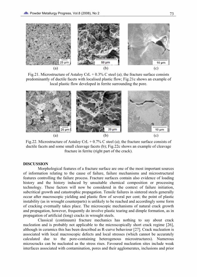
atmosphere of 25%H2+75%N2 with the dew point of -55°C and cooled at 10°C/min are shown in Fig.21a and Fig.22a. In CrL+0.3%C there is a mixture of upper bainite and ferrite, whereas in CrL+0.7%C it is upper bainite and some lower bainite, with small areas of acicular ferrite. The mechanical properties of CrL+0.3C were: Rpp0.2 = 442 MPa, Rm = 588 MPa, A = 2.3%, IE = 24 J, hardness of 166 HV 10; for CrL+0.7C, Rp0.2 = 510 MPa, Rm = 652 MPa, A = 2.0%, IE = 17 J, hardness of 246 HV 30.
The fracture modes of both steels, resembling wrought materials, were overwhelmingly ductile, Fig.21b and 22b, with dominant fine dimples initiated by the carbide phase. Localised plastic flow in ferrite and bainite surrounding a pore is shown in detail for CrL+0.3C in Fig.21c. With increasing load, bainite was seen to fail before the fracture of ferrite. For the 0.7%C steel some areas of cleavage fracture (Fig.22b) were detected in ferrite surrounded by the stronger bainite, as shown in Fig.22c.
Powder Metallurgy Progress, Vol.8 (2008), No 2 73
(a) (b) (c)
Fig.21. Microstructure of Astaloy CrL + 0.3% C steel (a); the fracture surface consists predominantly of ductile facets with localised plastic flow; Fig.21c shows an example of
local plastic flow developed in ferrite surrounding the pore.
(a) (b) (c)
Fig.22. Microstructure of Astaloy CrL + 0.7% C steel (a); the fracture surface consists of ductile facets and some small cleavage facets (b); Fig.22c shows an example of cleavage
fracture in ferrite (right part of the crack).
DISCUSSION Morphological features of a fracture surface are one of the most important sources
of information relating to the cause of failure, failure mechanisms and microstructural features controlling the failure process. Fracture surfaces contain also evidence of loading history and the history induced by unsuitable chemical composition or processing technology. These factors will now be considered in the context of failure initiation, subcritical growth and catastrophic propagation. Tensile failures in sintered steels generally occur after macroscopic yielding and plastic flow of several per cent; the point of plastic instability (as in wrought counterparts) is unlikely to be reached and accordingly some form of cracking eventually takes place. The microscopic mechanisms of natural crack growth and propagation, however, frequently do involve plastic tearing and dimple formation, as in propagation of artificial (long) cracks in wrought steels.
Classical (continuum) fracture mechanics has nothing to say about crack nucleation and is probably not applicable to the microscopically short crack regime [26], although in ceramics this has been described as R-curve behaviour [27]. Crack nucleation is associated with local macroscopic defects and local stresses (which cannot be accurately calculated due to the pore-containing heterogenous microstructures). Numerous microcracks can be nucleated as the stress rises. Favoured nucleation sites include weak interfaces associated with contamination, pores and their agglomerates, inclusions and prior

Powder Metallurgy Progress, Vol.8 (2008), No 2 74 particle boundaries. The freshly-nucleated microcracks have irregular contours, cannot be easily modelled and are quite unlike the cleavage cracks postulated to form by dislocation interactions. Their size appears to range from 10 to 20 microns.
Crack growth is controlled by the same microstructural criteria; the irregular paths are governed by microstructure. Paths chosen are “easy” and microcracks can be stopped by pores, or deflected, such that the driving force diminishes and the microcrack becomes non-propagating or dormant. The irregular shapes cannot be easily modelled, and R-curve behaviour can be used to describe this phenomenon of increasing size under increasing stresses. The size of initial microcracks ranged from 10 to 20 microns and grew to some 400 microns, thus a transition from “microstructurally short” crack to the “long” crack regime could take place [28].
A phenomenological model of the relationship between the fracture toughness, failure mechanisms and strength of the matrix for sintered steels [22] postulated the dependence of fracture toughness on the yield stress in areas with high porosity and that then the processes of plastic deformation and fracture are concentrated in sinter necks. In high density areas, K1C does not change; the failure mode is critically controlled by the material strength, so an increase of the yield strength results in a decrease of the critical defect size. Such a calculation will now be attempted with the estimated value of ψ of 0.58 to 0.72 (Table 1) [29].
Tab.1. Metallographic and theoretical (LEFMs) data for critical crack size.
Material σy[MPa]
σ [MPa]
KIC[MPa·m1/2]
ψ acri calculated [microns]
acri measured [microns]
DistAE+0.7C 466 603 25 0.712 390 350 - 420 CrL+0.3C 442 588 28 0.695 502 400 - 550 CrL+0.7C 510 652 25 0.719 337 200 -300
Fe-3Cu-0.7C 340 530 28 0.579 514 480 – 550
CONCLUSION Morphological features of a fracture surface are among the most important sources
of information relating to the cause of failure. A fracture surface contains evidence of loading history, microstructure characteristics as well as the defects induced by unsuitable chemical composition or processing technology. The interpretation of fracture surface details is often useful in determining the cause of failure and for potentially necessary changes in production technology of structural parts.
Acknowledgement The authors wish to thanks to the Slovak National Grant Agency (Project VEGA
2/6209/27, APVV LPP 0246-07) for financial support of this work.
REFERENCES [1] Metals Handbook. 9th ed. Vol. 12: Fractography, Ed. K. Mills et al. Metals Park : ASM
Int., 1987 [2] Pluhař, J.: Fyzikální metalurgie a mezní stavy materiálu (Physical metallurgy and limit
states of materials). STNL Alfa, 1987 [3] Koutský, J., Jandoš, F., Karel, V.: Lomy ocelových částí. Praha : SNTL, 1976 [4] Exner, HA., Pohl, D.: Powder Metallurgy International, vol. 10, 1978, no. 4, p. 193

Powder Metallurgy Progress, Vol.8 (2008), No 2 75 [5] Šlesár, M., Miškovič, M., Šalak, A., Dudrová, E. In: Int. Powder Metallurgy Conf. in
ČSSR, The High Tatras. Žilina : DT, 1974, p. 3, 71-85 [6] Dudrová, E., Parilák, Ľ., Rudnayová, E., Pelikán, K.: Powder Metallurgy International,
vol. 19, 1987, no. 3, p. 23 [7] Šlesár, M., Dudrová, E., Rudnayová, E.: Powder Metallurgy International, vol. 24,
1992, no. 4, p. 232 [8] Šlesár, M. In: Proc. Int.Conf. DFPM, Stará Lesná. Ed. Ľ.Parilák et al. Vol. 1. Košice :
IMR SAS, 1996, p. 85 [9] Pelikán, K.: Deformačné a lomové procesy v spekanom železe (Deformation and
Fracture Processes in Sintered Iron). Thesis. Košice : ÚMV SAV, 1986 [10] Weiss, B., Danninger, H., Stickler, R. In: Proceed. 1992 PM World Congress, Part:
Characterization of Powder & Compacts. June 21-26, San Francisco. MPIF, p. 171 [11] Danninger, H., Jangg, G., Weiss, B., Stickler, R.: Powder Metallurgy International, vol.
25, 1993, no. 3, p. 111 [12] Danninger, H., Spoljaric, D., Jangg, G., Weiss, B., Stickler, R.: Prakt. Metallogr., vol.
31, 1994, no. 2, p. 56 [13] Danninger, H., Weiss, B.: Journal of Materials Processing Technology, vol. 143-144,
2003, p. 179 [14] Xu, C., Danninger, H., Khatibi, G., Weiss, B.: Materials Science Forum, vol. 534-536,
2007, p. 685 [15] Moon, JR. In: Proc. Int.Conf. DFPM, Stará Lesná. Ed. Ľ.Parilák et al. Vol. 1. Košice :
IMR SAS, 1996, p. 61 [16] Moon, JR. In: Proc. Int.Conf. DFPM, Stará Lesná. Ed. Ľ.Parilák, H.Danninger. Vol. 1.
Košice : IMR SAS, 2002, p. 13 [17] Bergmark, A., Alzati, L., Persson, U. In: Proc. 2002 PM2 –Tech World Congress. Ed.
V. Arnhold et al. Vol. 5. Princeton : MPIF, 2002, p. 5/95 [18] Nakamura, M., Tsuya, K.: Powder Metall., vol. 22, 1979, no. 3, p. 101 [19] Fleck, NA., Smith, RA.: Powder Metall., vol. 24, 1981, no. 3, p. 121 [20] Pompe, W.: Powder Metall., vol. 27, 1984, no. 1, p. 45 [21] Straffelini, G., Molinari, A., Visintainer, C. In: Proc.2000 PM World Congress, Kyoto.
Ed. K. Kossuge, H. Nagai. Vol.2. JPMA, 2000, p. 1594 [22] Dudrová, E., Kabátová, M., Parilák, Ľ., Danninger, H. In: Proc.2000 PM World
Congress, Kyoto. Ed. K. Kossuge, H. Nagai. Vol. 1. JPMA, 2000, p. 24 [23] Chawla, N., Deng, X. In: Advances in Powder Metallurgy & Particulate Materials –
2003. Part 7. Las Vegas NV: MPIF, 2003, p. 257 [24] Rodziňák, D., Šlesár, M.: Powder Metallurgy Int., vol. 12, 1980, no. 3, p. 127 [25] Shelton, PV., Wronski, AS.: Metal Science, vol. 17, 1983, p. 533 [26] MillerR, K. J.: Materials Science and Technology, 9 (1993) 453-462. [27] Wronski, A. S.- Fourdeux, A.: Int. J. Fracture Mech., 1 (1965) 73-80. [28] Kabátová, M.- Dudrová, E.- Wronski, A. S.: Powder Metall., 49 (2006) 4, 363-368. [29] Dudrová, E.- Kabátová, M.: Fractography of Sintered Steels: A Review. Powder
Metallurgy World Congress and Exhibition. Euro PM 2004. Vol. 3. Vienna, 17.-21.10.2004. Ed. H.Danninger, R.Ratzi. EPMA 2004, s.193-198