Embed Size (px)
Citation preview
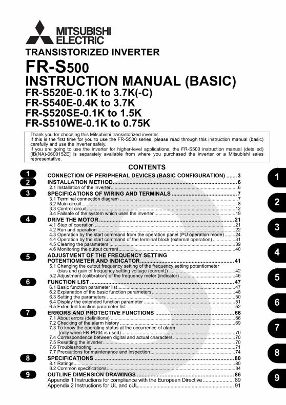
FR-S520E-0.1K to 3.7K(-C)FR-S540E-0.4K to 3.7KFR-S520SE-0.1K to 1.5KFR-S510WE-0.1K to 0.75K
1
2
3
4
5
6
7
8
9
HEAD OFFICE:TOKYO BLDG MARUNOUCHI TOKYO 100-8310
FR-S
500ETR
AN
SISTOR
IZED IN
VERTER
INSTR
UC
TION
MA
NU
AL (B
ASIC
)
C
TRANSISTORIZED INVERTER
FR-S500INSTRUCTION MANUAL (BASIC)
CONTENTSCONNECTION OF PERIPHERAL DEVICES (BASIC CONFIGURATION) ....... 3INSTALLATION METHOD.................................................................................. 62.1 Installation of the inverter................................................................................................6
SPECIFICATIONS OF WIRING AND TERMINALS ........................................... 73.1 Terminal connection diagram .........................................................................................73.2 Main circuit......................................................................................................................83.3 Control circuit ................................................................................................................123.4 Failsafe of the system which uses the inverter .............................................................19
DRIVE THE MOTOR ......................................................................................... 214.1 Step of operation ..........................................................................................................214.2 Run and operation ........................................................................................................224.3 Operation by the start command from the operation panel (PU operation mode) ........244.4 Operation by the start command of the terminal block (external operation) .................314.5 Clearing the parameters ...............................................................................................394.6 Monitoring the output current ........................................................................................40
ADJUSTMENT OF THE FREQUENCY SETTING POTENTIOMETER AND INDICATOR.............................................................. 415.1 Changing the output frequency setting of the frequency setting potentiometer
(bias and gain of frequency setting voltage (current)) ..................................................425.2 Adjustment (calibration) of the frequency meter (indicator) ..........................................46
FUNCTION LIST ............................................................................................... 476.1 Basic function parameter list.........................................................................................476.2 Explanation of the basic function parameters...............................................................486.3 Setting the parameters .................................................................................................506.4 Display the extended function parameter .....................................................................516.5 Extended function parameter list ..................................................................................52
ERRORS AND PROTECTIVE FUNCTIONS ....................................................667.1 About errors (definitions) ..............................................................................................667.2 Checking of the alarm history .......................................................................................697.3 To know the operating status at the occurrence of alarm
(only when FR-PU04 is used) ......................................................................................707.4 Correspondence between digital and actual characters...............................................707.5 Resetting the inverter....................................................................................................707.6 Troubleshooting ............................................................................................................717.7 Precautions for maintenance and inspection................................................................74
SPECIFICATIONS ............................................................................................808.1 Ratings..........................................................................................................................808.2 Common specifications.................................................................................................84
OUTLINE DIMENSION DRAWINGS ................................................................ 86Appendix 1 Instructions for compliance with the European Directive ...................... 89Appendix 2 Instructions for UL and cUL.................................................................... 91
Thank you for choosing this Mitsubishi transistorized inverter.If this is the first time for you to use the FR-S500 series, please read through this instruction manual (basic)carefully and use the inverter safely.If you are going to use the inverter for higher-level applications, the FR-S500 instruction manual (detailed)[IB(NA)-0600152E] is separately available from where you purchased the inverter or a Mitsubishi salesrepresentative.
IB(NA)-0600151E-C (0706) MEE Printed in Japan Specifications subject to change without notice.
123
4
5
6
7
8
9
A-1
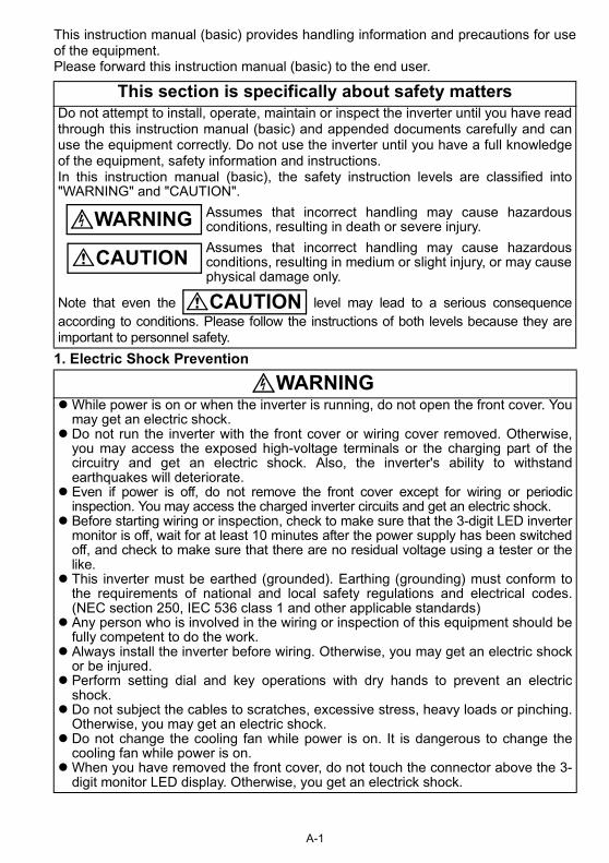
1. Electric Shock Prevention
This instruction manual (basic) provides handling information and precautions for useof the equipment.Please forward this instruction manual (basic) to the end user.
This section is specifically about safety mattersDo not attempt to install, operate, maintain or inspect the inverter until you have readthrough this instruction manual (basic) and appended documents carefully and canuse the equipment correctly. Do not use the inverter until you have a full knowledgeof the equipment, safety information and instructions.In this instruction manual (basic), the safety instruction levels are classified into"WARNING" and "CAUTION".
Assumes that incorrect handling may cause hazardousconditions, resulting in death or severe injury.Assumes that incorrect handling may cause hazardousconditions, resulting in medium or slight injury, or may causephysical damage only.
Note that even the level may lead to a serious consequenceaccording to conditions. Please follow the instructions of both levels because they areimportant to personnel safety.
WARNINGWhile power is on or when the inverter is running, do not open the front cover. Youmay get an electric shock.Do not run the inverter with the front cover or wiring cover removed. Otherwise,you may access the exposed high-voltage terminals or the charging part of thecircuitry and get an electric shock. Also, the inverter's ability to withstandearthquakes will deteriorate.Even if power is off, do not remove the front cover except for wiring or periodicinspection. You may access the charged inverter circuits and get an electric shock.Before starting wiring or inspection, check to make sure that the 3-digit LED invertermonitor is off, wait for at least 10 minutes after the power supply has been switchedoff, and check to make sure that there are no residual voltage using a tester or thelike. This inverter must be earthed (grounded). Earthing (grounding) must conform tothe requirements of national and local safety regulations and electrical codes.(NEC section 250, IEC 536 class 1 and other applicable standards)Any person who is involved in the wiring or inspection of this equipment should befully competent to do the work.Always install the inverter before wiring. Otherwise, you may get an electric shockor be injured.Perform setting dial and key operations with dry hands to prevent an electricshock.Do not subject the cables to scratches, excessive stress, heavy loads or pinching.Otherwise, you may get an electric shock.Do not change the cooling fan while power is on. It is dangerous to change thecooling fan while power is on.When you have removed the front cover, do not touch the connector above the 3-digit monitor LED display. Otherwise, you get an electrick shock.
WARNING
CAUTION
CAUTION
A-2
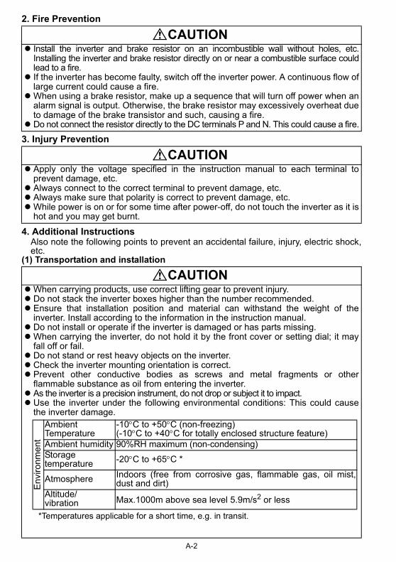
2. Fire Prevention
3. Injury Prevention
4. Additional InstructionsAlso note the following points to prevent an accidental failure, injury, electric shock,etc.
(1) Transportation and installation
CAUTIONInstall the inverter and brake resistor on an incombustible wall without holes, etc.Installing the inverter and brake resistor directly on or near a combustible surface couldlead to a fire.If the inverter has become faulty, switch off the inverter power. A continuous flow oflarge current could cause a fire.When using a brake resistor, make up a sequence that will turn off power when analarm signal is output. Otherwise, the brake resistor may excessively overheat dueto damage of the brake transistor and such, causing a fire.Do not connect the resistor directly to the DC terminals P and N. This could cause a fire.
CAUTIONApply only the voltage specified in the instruction manual to each terminal toprevent damage, etc.Always connect to the correct terminal to prevent damage, etc.Always make sure that polarity is correct to prevent damage, etc.While power is on or for some time after power-off, do not touch the inverter as it ishot and you may get burnt.
CAUTIONWhen carrying products, use correct lifting gear to prevent injury.Do not stack the inverter boxes higher than the number recommended.Ensure that installation position and material can withstand the weight of theinverter. Install according to the information in the instruction manual.Do not install or operate if the inverter is damaged or has parts missing.When carrying the inverter, do not hold it by the front cover or setting dial; it mayfall off or fail.Do not stand or rest heavy objects on the inverter.Check the inverter mounting orientation is correct.Prevent other conductive bodies as screws and metal fragments or otherflammable substance as oil from entering the inverter.As the inverter is a precision instrument, do not drop or subject it to impact.Use the inverter under the following environmental conditions: This could causethe inverter damage.
*Temperatures applicable for a short time, e.g. in transit.
Env
ironm
ent
Ambient Temperature
-10°C to +50°C (non-freezing)(-10°C to +40°C for totally enclosed structure feature)
Ambient humidity 90%RH maximum (non-condensing)Storagetemperature -20°C to +65°C *
Atmosphere Indoors (free from corrosive gas, flammable gas, oil mist,dust and dirt)
Altitude/vibration Max.1000m above sea level 5.9m/s2 or less
(2) Wiring
(3) Trial run
(4) Operation
Do not fit capacitive ecapacitor type filter (optiinverter.The connection orientatiodirection of rotation of the
Check all parameters, asudden start-up.When the load GD2 is smaoutput current may vary wIf this is a problem, set (When setting the PWM problem and take counte
When you have chosen restart suddenly after anSince the [STOP] key iprovide a circuit and swmechanical brake operatMake sure that the start do so may restart the moThe load used should bother electrical equipmenDo not modify the equipmDo not perform parts remlead to fault or damage o
CAUTIONquipment such as power factor correction capacitor,on FR-BIF(-H)) or surge suppressor to the output of the
n of the output cables U, V, W to the motor will affect the motor.
CAUTIONnd ensure that the machine will not be damaged by a
ll (at the motor GD or smaller) for 400V from 1.5K to 3.7K, thehen the output frequency is in the 20Hz to 30Hz range.the Pr.72 "PWM frequency selection" to 6kHz or higher.to a higher frequency, check for noise or leakage currentrmeasures against it.)
WARNINGthe retry function, stay away from the equipment as it will alarm stop.s valid only when functions are set (refer to page 59),itch separately to make an emergency stop (power off,ion for emergency stop, etc).signal is off before resetting the inverter alarm. A failure totor suddenly.e a three-phase induction motor only. Connection of anyt to the inverter output may damage the equipment.ent.oval which is not instructed in this manual. Doing so mayf the inverter.
A-3
(5) Emergency stop
(6) Maintenance, inspectio
(7) Disposing of the invert
(8) General instructions
The electronic thermal rfrom overheating.Do not use a magnetic coof the inverter.Use a noise filter to redunearby electronic equipmTake measures to supprthe inverter may heat/daWhen a 400V class momotor or measures takenthe wiring constants maythe motor.When parameter clear obefore starting operationThe inverter can be easetting, fully examine theIn addition to the inverter'sBefore running an inveperform inspection and te
Provide a safety backumachine and equipment When the breaker on thecircuit), damage to internthen remove the cause aWhen any protective funthen reset the inverter, a
Do not carry out a megginverter.
Treat as industrial waste
Many of the diagrams and dwithout a cover, or partially opthe cover and follow this instr
n and parts replacement
er
CAUTIONelay function does not guarantee protection of the motor
ntactor on the inverter input for frequent starting/stopping
ce the effect of electromagnetic interference. Otherwiseent may be affected.ess harmonics. Otherwise power supply harmonics frommage the power capacitor and generator.tor is inverter-driven, please use an insulation-enhanced to suppress surge voltages. Surge voltages attributable to occur at the motor terminals, deteriorating the insulation of
r all clear is performed, reset the required parameterss. Each parameter returns to the factory setting.sily set for high-speed operation. Before changing its performances of the motor and machine. holding function, install a holding device to ensure safety.rter which had been stored for a long period, alwaysst operation.
CAUTIONp such as an emergency brake which will prevent thefrom hazardous conditions if the inverter fails. inverter primary side trips, check for the wiring fault (shortal parts of the inverter, etc. Identify the cause of the trip,
nd power on the breaker. ction is activated, take the appropriate corrective action,nd resume operation.
CAUTIONer (insulation resistance) test on the control circuit of the
A-4
CAUTION.
rawings in this instruction manual (basic) show the inverteren. Never operate the inverter in this manner. Always replaceuction manual (basic) when operating the inverter.
1
All models of general-purpose inverters used by specific consumers are covered by"Harmonic suppression guideline for consumers who receive high voltage or specialhigh voltage". (For further details, refer to Instruction Manual (detailed).)
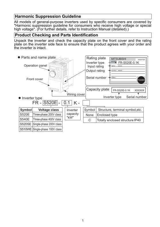
Unpack the inverter and check the capacity plate on the front cover and the ratingplate on the inverter side face to ensure that the product agrees with your order andthe inverter is intact.
Harmonic Suppression Guideline
Product Checking and Parts Identification
Front cover
Operation panel
Wiring cover
Input rating
Output rating
Serial number
Rating plate
Inverter type
FR - S520E - K -0.1
Symbol
None
C
Structure, terminal symbol,etc.
Enclosed type
Totally enclosed structure IP40
Inverter type Serial number
Inverter capacity "kW"
Symbol Voltage class
S520E Three-phase 200V class
Capacity plate
S540E Three-phase 400V class
S520SE Single-phase 200V class
S510WE Single-phase 100V class
� Parts and name plate
� Inverter type
FR-S520E-0.1K
FR-S520E-0.1K XXXXXX
2
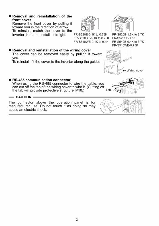
Removal and reinstallation of thefront coverRemove the front cover by pulling ittoward you in the direction of arrow.To reinstall, match the cover to theinverter front and install it straight.
Removal and reinstallation of the wiring cover The cover can be removed easily by pulling it towardyou.To reinstall, fit the cover to the inverter along the guides.
RS-485 communication connectorWhen using the RS-485 connector to wire the cable, youcan cut off the tab of the wiring cover to wire it. (Cutting offthe tab will provide protective structure IP10.)
CAUTIONThe connector above the operation panel is formanufacturer use. Do not touch it as doing so maycause an electric shock.
FR-S520E-0.1K to 0.75K
FR-S520SE-0.1K to 0.75K
FR-S510WE-0.1K to 0.4K
FR-S520E-1.5K to 3.7K
FR-S520SE-1.5K
FR-S540E-0.4K to 3.7K
FR-S510WE-0.75K
Wiring cover
Tab

3
1
CO
NN
ECTI
ON
OF
PER
IPH
ERA
L D
EVIC
ES (B
ASI
C C
ON
FIG
UR
ATI
ON
)
1. CONNECTION OF PERIPHERAL DEVICES (BASIC CONFIGURATION)
Power supplyUse within the permissible power supply specifications of the inverter. (Refer to page 80.)
Moulded case circuit breaker or earth leakage circuit breakerThe breaker must be selected carefully since an in-rush current flows in the inverter at power on.Magnetic contactorInstall for your safety. Do not use this magnetic contactor to start and stop the inverter. Doing so will cause the inverter life to be shorten. (Refer to page 18.)
Installation of a reactorA reactor must be used when the power harmonics measure is taken, power factor is to be improved or the inverter is installed near a large supply system (500kVA or more and wiring distance within 10 m). Make the selection carefully.
Devices connected to the outputDo not install a power factor correction capacitor, surgesuppressor or capacitor type filter on the output side of theinverter. When installing a moulded case circuit breaker on the output side of the inverter, contact each manufacturer for selection of the moulded case circuit breaker.Earth (Ground)To prevent an electric shock, always earth (ground) themotor and inverter. For reduction of induction noise from the power line ofthe inverter, it is recommended to wire the earth(ground) cable by returning it to the earth (ground)terminal of the inverter.(For details of noise reduction techniques, refer to the instruction manual (detailed).)
(MC)
(MCCB)
or (ELB)
AC reactor
(FR-HAL
/FR-BAL)
DC reactor
(FR-HEL
/FR-BEL)
Inverter
(FR-S500E)
Motor
Earth (Ground)
Earth (Ground)Earth (Ground)
InverterThe life of the inverter is influenced by ambient temperature. Check the ambient temperature. Epecially when mounting the inverter inside an enclosure, take cautions of the ambient temperature. (Refer to page 85.) Wrong wiring might lead to damage of the inverter.The control signal wires must be kept fully away from themain circuit to protect them from noise. (Refer to page 7.)

CONNECTION OF PERIPHERAL DEVICES (BASIC CONFIGURATION)
4
1) Three-phase 200V power input
2) Three-phase 400V power input
Selection of peripheral devices (selection changes with the power inputspecifications of the inverter)
MotorOutput (kW)
Applied Inverter Type
Moulded Case Circuit Breaker (MCCB *1, 4) orEarth Leakage Circuit Breaker
(ELB) (*2, 4)
Magnetic Contactor
(MC)(Refer to page 18)
AC ReactorFR-HAL- KFR-BAL- K
DC ReactorFR-HEL- KFR-BEL- K
0.1 FR-S520E-0.1K(-C) 30AF/5A S-N10 0.4 (*3) 0.4 (*3)0.2 FR-S520E-0.2K(-C) 30AF/5A S-N10 0.4 (*3) 0.4 (*3)0.4 FR-S520E-0.4K(-C) 30AF/5A S-N10 0.4 0.40.75 FR-S520E-0.75K(-C) 30AF/10A S-N10 0.75 0.751.5 FR-S520E-1.5K(-C) 30AF/15A S-N10 1.5 1.52.2 FR-S520E-2.2K(-C) 30AF/20A S-N10 2.2 2.2
3.7 FR-S520E-3.7K(-C) 30AF/30A S-N20, S-N21 3.7 3.7
MotorOutput (kW)
Applied Inverter Type
Moulded Case Circuit Breaker (MCCB *1, 4) orEarth Leakage Circuit Breaker
(ELB) (*2, 4)
Magnetic Contactor
(MC)(Refer to page 18)
AC ReactorFR-HAL- KFR-BAL- K
DC ReactorFR-HEL- KFR-BEL- K
0.4 FR-S540E-0.4K 30AF/5A S-N10 H0.4 H0.40.75 FR-S540E-0.75K 30AF/5A S-N10 H0.75 H0.751.5 FR-S540E-1.5K 30AF/10A S-N10 H1.5 H1.52.2 FR-S540E-2.2K 30AF/15A S-N10 H2.2 H2.2
3.7 FR-S540E-3.7K 30AF/20A S-N20, S-N21 H3.7 H3.7
CO
NN
ECTI
ON
OF
PER
IPH
ERA
L D
EVIC
ES (B
ASI
C C
ON
FIG
UR
ATI
ON
)
CONNECTION OF PERIPHERAL DEVICES(BASIC CONFIGURATION)
5
1
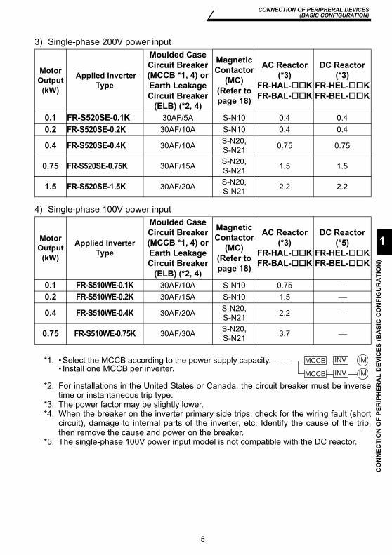
3) Single-phase 200V power input
4) Single-phase 100V power input
*2. For installations in the United States or Canada, the circuit breaker must be inversetime or instantaneous trip type.
*3. The power factor may be slightly lower.*4. When the breaker on the inverter primary side trips, check for the wiring fault (short
circuit), damage to internal parts of the inverter, etc. Identify the cause of the trip,then remove the cause and power on the breaker.
*5. The single-phase 100V power input model is not compatible with the DC reactor.
Motor Output
(kW)
Applied Inverter Type
Moulded Case Circuit Breaker (MCCB *1, 4) orEarth Leakage Circuit Breaker
(ELB) (*2, 4)
Magnetic Contactor
(MC)(Refer to page 18)
AC Reactor (*3)
FR-HAL- KFR-BAL- K
DC Reactor (*3)
FR-HEL- KFR-BEL- K
0.1 FR-S520SE-0.1K 30AF/5A S-N10 0.4 0.40.2 FR-S520SE-0.2K 30AF/10A S-N10 0.4 0.4
0.4 FR-S520SE-0.4K 30AF/10A S-N20, S-N21 0.75 0.75
0.75 FR-S520SE-0.75K 30AF/15A S-N20, S-N21 1.5 1.5
1.5 FR-S520SE-1.5K 30AF/20A S-N20, S-N21 2.2 2.2
Motor Output
(kW)
Applied Inverter Type
Moulded Case Circuit Breaker (MCCB *1, 4) orEarth Leakage Circuit Breaker
(ELB) (*2, 4)
Magnetic Contactor
(MC)(Refer to page 18)
AC Reactor (*3)
FR-HAL- KFR-BAL- K
DC Reactor (*5)
FR-HEL- KFR-BEL- K
0.1 FR-S510WE-0.1K 30AF/10A S-N10 0.75 ⎯0.2 FR-S510WE-0.2K 30AF/15A S-N10 1.5 ⎯
0.4 FR-S510WE-0.4K 30AF/20A S-N20, S-N21 2.2 ⎯
0.75 FR-S510WE-0.75K 30AF/30A S-N20, S-N21 3.7 ⎯
*1. •Select the MCCB according to the power supply capacity.• Install one MCCB per inverter.
INV
INV
IM
IM
MCCB
MCCB
6
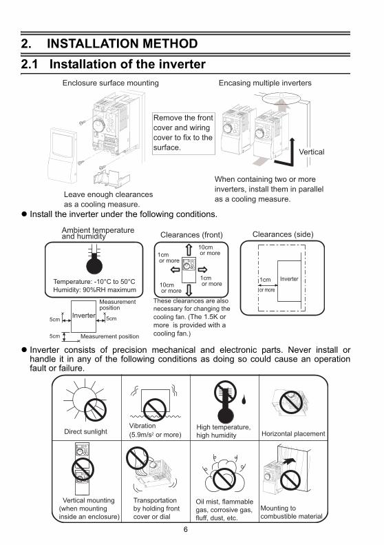
Installation of the inverter
2. INSTALLATION METHOD2.1 Installation of the inverter
Install the inverter under the following conditions.
Inverter consists of precision mechanical and electronic parts. Never install orhandle it in any of the following conditions as doing so could cause an operationfault or failure.
When containing two or more
inverters, install them in parallel
as a cooling measure.Leave enough clearances
as a cooling measure.
Enclosure surface mounting Encasing multiple inverters
Remove the front
cover and wiring
cover to fix to the
surface.Vertical
Ambient temperature and humidity Clearances (front)
These clearances are also
necessary for changing the
cooling fan. (The 1.5K or
more is provided with a
cooling fan.)Measurement position
5cm5cm
Measurementposition
5cm
Inverter
Temperature: -10°C to 50°C
Humidity: 90%RH maximum
10cm or more1cm
or more
10cm or more
1cm or more
Clearances (side)
Inverter1cm
or more
Direct sunlightVibration
(5.9m/s2 or more)High temperature,
high humidity
Oil mist, flammable
gas, corrosive gas,
fluff, dust, etc.
Horizontal placement
Transportation
by holding front
cover or dial
Vertical mounting
(when mounting
inside an enclosure)
Mounting to
combustible material
Terminal connection diagram
SPEC
IFIC
ATI
ON
S O
F W
IRIN
G A
ND
TER
MIN
ALS
7
3
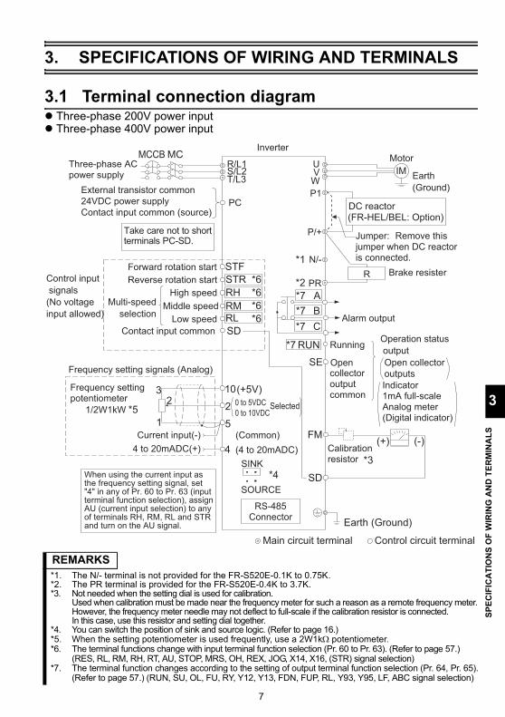
3. SPECIFICATIONS OF WIRING AND TERMINALS
3.1 Terminal connection diagramThree-phase 200V power inputThree-phase 400V power input
REMARKS*1. The N/- terminal is not provided for the FR-S520E-0.1K to 0.75K.*2. The PR terminal is provided for the FR-S520E-0.4K to 3.7K.*3. Not needed when the setting dial is used for calibration.
Used when calibration must be made near the frequency meter for such a reason as a remote frequency meter.However, the frequency meter needle may not deflect to full-scale if the calibration resistor is connected.In this case, use this resistor and setting dial together.
*4. You can switch the position of sink and source logic. (Refer to page 16.)*5. When the setting potentiometer is used frequently, use a 2W1kΩ potentiometer.*6. The terminal functions change with input terminal function selection (Pr. 60 to Pr. 63). (Refer to page 57.)
(RES, RL, RM, RH, RT, AU, STOP, MRS, OH, REX, JOG, X14, X16, (STR) signal selection)*7. The terminal function changes according to the setting of output terminal function selection (Pr. 64, Pr. 65).
(Refer to page 57.) (RUN, SU, OL, FU, RY, Y12, Y13, FDN, FUP, RL, Y93, Y95, LF, ABC signal selection)
InverterMotor
IMUVW
RUN
SE
Running
Alarm output
Operation status
output
Open collector
Open collector
outputs
A
B
C
Frequency setting potentiometer
1/2W1kW
Frequency setting signals (Analog)
10
22
3
1
4 to 20mADC(+) 4
0 to 5VDC
0 to 10VDC
5Current input(-)
(+5V)
(Common)
(4 to 20mADC)
Selected
output common
Low speed RL
MCCB MC
DC reactor(FR-HEL/BEL: Option)
Jumper: Remove this jumper when DC reactoris connected.
P1
SINK
SOURCE
Multi-speed
selection
Take care not to short terminals PC-SD.
RS-485 Connector
Three-phase AC power supply
Control circuit terminalMain circuit terminal
When using the current input as the frequency setting signal, set "4" in any of Pr. 60 to Pr. 63 (inputterminal function selection), assign AU (current input selection) to anyof terminals RH, RM, RL and STR and turn on the AU signal.
Control input
signals
(No voltage
input allowed)
STF
STR
RM
Forward rotation start
Reverse rotation start
Middle speed
High speed RH
*3
FM
SD
(+)Calibration resistor
(-)
Earth (Ground)
R Brake resister
Earth
(Ground)External transistor common
24VDC power supply
Contact input common (source)
SD
PC
Contact input common
Indicator1mA full-scale Analog meter(Digital indicator)
*6
*4
*6
*6
*6
*7
*7
*7
*7
*1
*2
*5
PR
R/L1S/L2T/L3
P/+
N/-
Main circuit
8
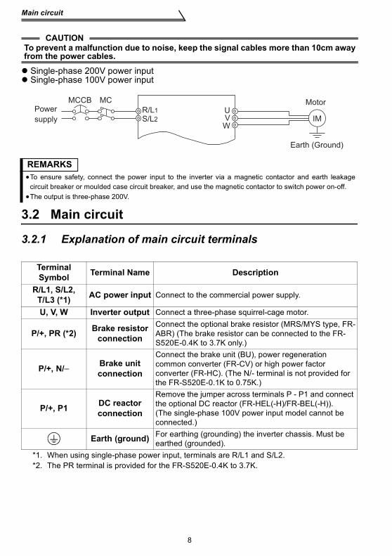
Single-phase 200V power inputSingle-phase 100V power input
3.2 Main circuit
3.2.1 Explanation of main circuit terminals
CAUTIONTo prevent a malfunction due to noise, keep the signal cables more than 10cm awayfrom the power cables.
REMARKS•To ensure safety, connect the power input to the inverter via a magnetic contactor and earth leakage
circuit breaker or moulded case circuit breaker, and use the magnetic contactor to switch power on-off.•The output is three-phase 200V.
Terminal Symbol Terminal Name Description
R/L1, S/L2, T/L3 (*1) AC power input Connect to the commercial power supply.
U, V, W Inverter output Connect a three-phase squirrel-cage motor.
P/+, PR (*2) Brake resistor connection
Connect the optional brake resistor (MRS/MYS type, FR-ABR) (The brake resistor can be connected to the FR-S520E-0.4K to 3.7K only.)
P/+, N/− Brake unit connection
Connect the brake unit (BU), power regeneration common converter (FR-CV) or high power factor converter (FR-HC). (The N/- terminal is not provided for the FR-S520E-0.1K to 0.75K.)
P/+, P1 DC reactor connection
Remove the jumper across terminals P - P1 and connect the optional DC reactor (FR-HEL(-H)/FR-BEL(-H)).(The single-phase 100V power input model cannot be connected.)
Earth (ground) For earthing (grounding) the inverter chassis. Must be earthed (grounded).
*1. When using single-phase power input, terminals are R/L1 and S/L2.*2. The PR terminal is provided for the FR-S520E-0.4K to 3.7K.
MCCB
IMUVW
MCPower
supply
Motor
Earth (Ground)
S/L2
R/L1

Main circuit
SPEC
IFIC
ATI
ON
S O
F W
IRIN
G A
ND
TER
MIN
ALS
9
3
3.2.2 Terminal block layout1)Three-phase 200V power input• FR-S520E-0.1K, 0.2K (-C) • FR-S520E-1.5K, 2.2K, 3.7K (-C)
• FR-S520E-0.4K, 0.75K (-C)
2)Three-phase 400V power input• FR-S540E-0.4K, 0.75K, 1.5K, 2.2K, 3.7K (-C)
P/+P1
U V W
IM
R/L1 S/L2 T/L3
Jumper
Power supply Motor
P1
Jumper
Power supply Motor
U V W
IM
N/- P/+
R/L1 S/L2 T/L3
PR
P1
Motor
Jumper
U V W
IM
Power supply
R/L1 S/L2
P/+PR
T/L3
P1
Jumper
Power supply Motor
U V W
IM
P/+
R/L1 S/L2 T/L3
N/-
Main circuit
10
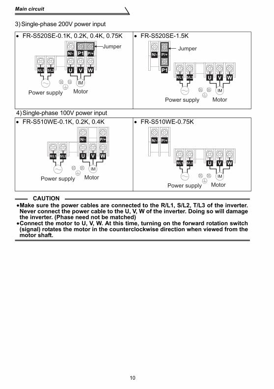
3)Single-phase 200V power input
• FR-S520SE-0.1K, 0.2K, 0.4K, 0.75K • FR-S520SE-1.5K
4)Single-phase 100V power input• FR-S510WE-0.1K, 0.2K, 0.4K • FR-S510WE-0.75K
CAUTION•Make sure the power cables are connected to the R/L1, S/L2, T/L3 of the inverter.Never connect the power cable to the U, V, W of the inverter. Doing so will damagethe inverter. (Phase need not be matched)•Connect the motor to U, V, W. At this time, turning on the forward rotation switch(signal) rotates the motor in the counterclockwise direction when viewed from themotor shaft.
P1
Motor
Jumper
U V W
IM
Power supply
R/L1 S/L2
P/+N/-
P1
Jumper
Motor
U V W
IM
Power supply
P/+N/-
R/L1 S/L2
Motor
U V W
IM
Power supply
R/L1 S/L2
P/+N/-
Motor
U V W
IM
Power supply
P/+N/-
R/L1 S/L2

11
Main circuit
3
SPEC
IFIC
ATI
ON
S O
F W
IRIN
G A
ND
TER
MIN
ALS
3.2.3 Cables, wiring length, and crimping terminalsThe following table indicates a selection example for the wiring length of 20m. 1) Three-phase 200V power input
2) Three-phase 400V power input
3) Single-phase 200V power input
4) Single-phase 100V power input
Wiring length100m maximum. (50m maximum for the FR-S540E-0.4K.)
Applied Inverter
Ter-minalScrewsize
Tight-ening
TorqueN⋅m
Crimping Terminal
Cable SizeHIV cable
(mm2)AWG
PVC cable(mm2)
R, S, T U, V, W R, S, T U, V, W R, S, T U, V, W R, S, T U, V, WFR-S520E-0.1K to 0.75K (-C) M3.5 1.2 2-3.5 2-3.5 2 2 14 14 2.5 2.5
FR-S520E-1.5K, 2.2K (-C) M4 1.5 2-4 2-4 2 2 14 14 2.5 2.5
FR-S520E-3.7K (-C) M4 1.5 5.5-4 5.5-4 3.5 3.5 12 12 4 2.5
Applied Inverter
Ter-minalScrewsize
Tight-ening
TorqueN⋅m
Crimping Terminal
Cable SizeHIV cable
(mm2)AWG
PVC cable(mm2)
R, S, T U, V, W R, S, T U, V, W R, S, T U, V, W R, S, T U, V, WFR-S540E-0.4K to 3.7K M4 1.5 2-4 2-4 2 2 14 14 2.5 2.5
Applied Inverter
Termi-nal
Screwsize
Tight-ening
TorqueN⋅m
Crimping Terminal
CableHIV cable
(mm2)AWG
PVC Cable(mm2)
R, S U, V, W R, S U, V, W R, S U, V, W R, S U, V, WFR-S520SE-0.1K to 0.75K M3.5 1.2 2-3.5 2-3.5 2 2 14 14 2.5 2.5
FR-S520SE-1.5K M4 1.5 2-4 2-4 2 2 14 14 2.5 2.5
Applied Inverter
Termi-nal
Screwsize
Tight-ening
TorqueN⋅m
Crimping Terminal
Cable SizeHIV cable
(mm2)AWG
PVC cable(mm2)
R, S U, V, W R, S U, V, W R, S U, V, W R, S U, V, WFR-S510WE-0.1K to 0.4K M3.5 1.2 2-3.5 2-3.5 2 2 14 14 2.5 2.5
FR-S510WE-0.75K M4 1.5 5.5-4 2-4 3.5 2 12 14 4 2.5
CAUTION•When the wiring length of the 0.1K and 0.2K of the three-phase 200V, single-phase 200V, and single-phase 100V class and the 0.4K and 0.75K of the three-phase 400V class is 30m or more, set the carrier frequency to 1kHz.•When automatic torque boost is selected in Pr. 98 "automatic torque boostselection (motor capacity)", the wiring length should be 30m maximum. (Referto page 60.)
Control circuit
12
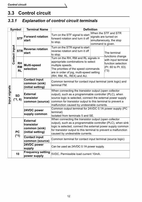
3.3 Control circuit3.3.1 Explanation of control circuit terminals
Symbol Terminal Name Definition
Inpu
t sig
nals
Con
tact
inpu
t
STF Forward rotation start
Turn on the STF signal to start forward rotation and turn it off to stop.
When the STF and STR signals are turned on simultaneously, the stop command is given.
STR Reverse rotation start
Turn on the STR signal to start reverse rotation and turn it off to stop. The terminal
functions change with input terminal function selection (Pr. 60 to Pr. 63).(*3)
RHRMRL
Multi-speed selection
Turn on the RH, RM and RL signals in appropriate combinations to select multiple speeds.The priorities of the speed commands are in order of jog, multi-speed setting (RH, RM, RL, REX) and AU.
SD(*1, 6)
Contact input common (sink)(initial setting)
Common terminal for contact input terminal (sink logic) and terminal FM.
External transistor common (source)
When connecting the transistor output (open collector output), such as a programmable controller (PLC), when source logic is selected, connect the external power supply common for transistor output to this terminal to prevent a malfunction caused by undesirable currents.
24VDC power supply common
Common output terminal for 24VDC 0.1A power supply (PC terminal)Isolated from terminals 5 and SE.
PC(*1)
External transistor common (sink) (initial setting)
When connecting the transistor output (open collector output), such as a programmable controller (PLC), when sink logic is selected, connect the external power supply common for transistor output to this terminal to prevent a malfunction caused by undesirable currents.
Contact input common (source) Common terminal for contact input terminal (source logic)
24VDC power supply Can be used as 24VDC 0.1A power supply.
10 Frequency setting power supply 5VDC, Permissible load current 10mA.

Control circuit
SPEC
IFIC
ATI
ON
S O
F W
IRIN
G A
ND
TER
MIN
ALS
13
3
*1. Do not connect terminals SD and PC each other or to the earth (ground).For sink logic (factory setting), terminal SD acts as the common terminal of contact input. Forsource logic, terminal PC acts as the common terminal of contact input. (Refer to the separatelyavailable instruction manual (detailed) for switching method.)
*2. Low indicates that the open collector output transistor is on (conducts). High indicates that thetransistor is off (does not conduct).
*3. RL, RM, RH, RT, AU, STOP, MRS, OH, REX, JOG, RES, X14, X16, (STR) signal selection(Refer to page 57.)
*4. RUN, SU, OL, FU, RY, Y12, Y13, FDN, FUP, RL, Y93, Y95, LF, ABC signal selection (Refer topage 57.)
*5. To be compliant with the European Directive (Low Voltage Directive), the operating capacity ofrelay outputs (A, B, C) should be 30VDC 0.3A.
*6. Terminals SD, SE and 5 are isolated from each other. Do not earth (ground).
Inpu
t sig
nals
Freq
uenc
y se
tting
2 Frequency setting (voltage signal)
Inputting 0 to 5VDC (or 0 to 10V) provides the maximum output frequency at 5V (10V) and makes input and output proportional.Switch between 5V and 10V using Pr. 73 "0-5V, 0-10V selection".Input resistance 10kΩ. Maximum permissible input voltage 20V
4 Frequency setting (current signal)
Input 4 to 20mADC. It is factory set at 0Hz for 4mA and at 60Hz for 20mA.Maximum permissible input current 30mA. Input resistance approximately 250Ω.Turn ON signal AU for current input.Turning the AU signal on makes voltage input invalid. Use any of Pr. 60 to Pr. 63 (input terminal function selection) to set the AU signal.
5 Frequency setting input common
Frequency setting signal (terminal 2, 4) common terminal. (*6)
Out
put s
igna
ls
ABC
Alarm output
1 changeover contact output indicates that the inverter protective function has activated and the output stopped. 230VAC 0.3A, 30VDC 0.3A. Alarm: discontinuity across B-C (continuity across A-C), Normal: continuity across B-C (discontinuity across A-C).(*5)
The function of the terminals changes according to the output terminal function selection (Pr. 64, Pr. 65).(*4)
Ope
n co
llect
or
RUN Inverterrunning
Switched low when the inverter output frequency is equal to or higher than the starting frequency (factory set to 0.5Hz variable). Switched high during stop or DC injection brake operation. (*2) Permissible load 24VDC 0.1A (a voltage drop is 3.4V maximum when the signal is on)
SE Open collector common Common terminal for inverter running terminal RUN. (*6)
Indi
cato
r
FM For meter
The output signal across terminals FM-SD is factory set to about 1mA at 60Hz and is proportional to the corresponding output frequency. Since output voltage is pulse waveform, a digital meter can be connected.Frequency permissible load current 1mAPulse specification 1440 pulses/s at 60Hz
Com
mun
icat
ion
—— RS-485connector
Using the parameter unit connection cable (FR-CB201 to 205), the parameter unit (FR-PU04) can be connected.Communication operation can be performed using RS-485.For details of RS-485 communication, refer to the separately available instruction manual (detailed).
Symbol Terminal Name Definition

Control circuit
14
3.3.2 Arrangement and wiring of control circuit terminals
*Information on bar terminalsIntroduced products (as of September, 2006): Phoenix Contact Co.,Ltd.
Bar terminal crimping tool: CRIMPFOX ZA3 (Phoenix Contact Co., Ltd.)
C
ontro
l circ
uit t
erm
inal
blo
ck
Loosen the terminal screw and insert the cable into the terminal.
Screw size: M3 (A, B, C terminals), M2 (other than the above)
Tightening torque: 0.5N•m to 0.6N•m (A, B, C termi-nals)0.22N•m to 0.25N•m (other than the above)
Cable size: 0.3mm2 to 0.75mm2
Screwdriver: Small flat-blade screwdriverTip thickness: 0.4mmTip width: 2.5mm
Terminal Screw Size Bar Terminal Model(With Insulation Sleeve)
Bar Terminal Model(Without Insulation Sleeve) Wire Size (mm2)
M3 (A, B, C terminal)AI 0,5-6 WH A 0,5-6 0.3 to 0.5AI 0,75-6 GY A 0,75-6 0.5 to 0.75
M2 (Other than the above) AI 0,5-6 WH A 0,5-6 0.3 to 0.5
CAUTIONWhen using the bar terminal (without insulation sleeve), use care so that thetwisted wires do not come out.
PC
A B
SE RUN 10 2 5 4
SD STF STR RM RHSD
C
RL FM
CAUTIONUndertightening can cause cable disconnection or malfunction. Overtightening can cause a short circuit or malfunction due to damage to the screw or unit.
Cable stripping size
Wire the stripped cable after twisting it to prevent it from becoming loose.In addition, do not solder it. *
ABC terminals 6mm
Other than the above 5mm

Control circuit
SPEC
IFIC
ATI
ON
S O
F W
IRIN
G A
ND
TER
MIN
ALS
15
3
3.3.3 Connection to RS-485 connector(1) When connecting the parameter unit
Use the optional FR-CB2 . When the parameter unit (FR-PU04) is used,operation from the operation panel is not accepted. ( is valid)
(2) RS-485 communicationUsing the RS-485 connector, you can perform communication operation from apersonal computer etc. By connecting the RS-485 connector to computers suchas personal computer and FA with a communication cable, you can run/monitorthe inverter and read/write parameter values using a user program. For furtherdetails, refer to the instruction manual (detailed).· Conforming standard: EIA-485 (RS-485)· Transmission format: Multi-drop link· Communication speed: Maximum 19200 bps· Overall extension: 500m
CAUTIONDo not plug the connector to a computer LAN board, fax modem socket, tele-phone modular connector etc. The inverter and machine could be damageddue to differences in electrical specifications.
STOPRESET

Control circuit
16
3.3.4 Changing the control logicThe input signals are set to sink logic.To change the control logic, the jumper connector under the setting dial must be moved to the other position.
Change the jumper connector position using tweezers, a pair of long-nose pliers etc.Change the jumper connector position before switching power on.
CAUTION•Make sure that the front cover is installed securely.•The front cover is fitted with the capacity plate and the inverter unit with therating plate. Since these plates have the same serial numbers, always replacethe removed cover onto the original inverter.•The sink-source logic change-over jumper connector must be fitted in onlyone of those positions. If it is fitted in both positions at the same time, theinverter may be damaged.
1) Sink logic type• In this logic, a signal switches on when a current flows from the corresponding signal
input terminal.Terminal SD is common to the contact input signals. Terminal SE is common to theopen collector output signals.
• Use terminal PC as a common terminal, and perform wiring as shown on the right. (Do not connect terminal SD of the inverter with terminal 0V of the external power supply. When using terminals PC-SD as a 24VDC power supply, do not install a power supply in parallel in the outside of the inverter. Doing so may cause a malfunction due to undesirable current.)
Current
SD
STFR
STRR
Sink
connector
Sink logicDC input (sink type)
<Example: QX40>Inverter
24VDC
RUN
SE
TB1
TB17
R
R
Current flow
QY40P type transistor
output unit
TB1
TB2
TB17
TB18
24VDC SD
PC
STR
STF
Inverter
24VDC
(SD)
Current flow
Constant voltage circuit
SPEC
IFIC
ATI
ON
S O
F W
IRIN
G A
ND
TER
MIN
ALS
Control circuit
17
3
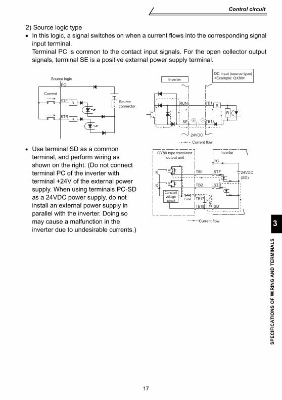
2) Source logic type• In this logic, a signal switches on when a current flows into the corresponding signal
input terminal.Terminal PC is common to the contact input signals. For the open collector outputsignals, terminal SE is a positive external power supply terminal.
• Use terminal SD as a common terminal, and perform wiring as shown on the right. (Do not connect terminal PC of the inverter with terminal +24V of the external power supply. When using terminals PC-SD as a 24VDC power supply, do not install an external power supply in parallel with the inverter. Doing so may cause a malfunction in the inverter due to undesirable currents.)
Current
PC
STFR
STR
Source logic
Source
connector
R
DC input (source type)
<Example: QX80>
24VDC
RUN
SE
TB1
TB18
R
Inverter
R
Current flow
QY80 type transistor
output unit
Constant
voltage
circuit
PC
TB1
TB2
TB17Fuse
TB18
STF
STR
SD
Inverter
24VDC
(SD)
24V
DC
Current flow
18
Control circuit
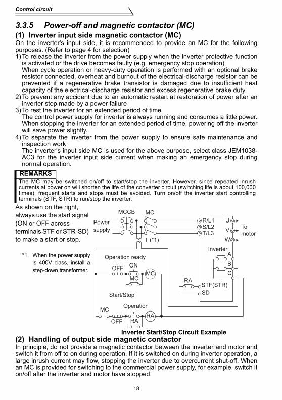
3.3.5 Power-off and magnetic contactor (MC)(1) Inverter input side magnetic contactor (MC)On the inverter's input side, it is recommended to provide an MC for the followingpurposes. (Refer to page 4 for selection)1)To release the inverter from the power supply when the inverter protective function
is activated or the drive becomes faulty (e.g. emergency stop operation)When cycle operation or heavy-duty operation is performed with an optional brakeresistor connected, overheat and burnout of the electrical-discharge resistor can beprevented if a regenerative brake transistor is damaged due to insufficient heatcapacity of the electrical-discharge resistor and excess regenerative brake duty.
2)To prevent any accident due to an automatic restart at restoration of power after aninverter stop made by a power failure
3)To rest the inverter for an extended period of timeThe control power supply for inverter is always running and consumes a little power.When stopping the inverter for an extended period of time, powering off the inverterwill save power slightly.
4)To separate the inverter from the power supply to ensure safe maintenance andinspection workThe inverter's input side MC is used for the above purpose, select class JEM1038-AC3 for the inverter input side current when making an emergency stop duringnormal operation.
(2) Handling of output side magnetic contactorIn principle, do not provide a magnetic contactor between the inverter and motor andswitch it from off to on during operation. If it is switched on during inverter operation, alarge inrush current may flow, stopping the inverter due to overcurrent shut-off. Whenan MC is provided for switching to the commercial power supply, for example, switch iton/off after the inverter and motor have stopped.
REMARKSThe MC may be switched on/off to start/stop the inverter. However, since repeated inrushcurrents at power on will shorten the life of the converter circuit (switching life is about 100,000times), frequent starts and stops must be avoided. Turn on/off the inverter start controllingterminals (STF, STR) to run/stop the inverter.
As shown on the right, always use the start signal (ON or OFF across terminals STF or STR-SD) to make a start or stop.
*1. When the power supplyis 400V class, install astep-down transformer.
Inverter Start/Stop Circuit Example
MCCB
OFFON
MCMC
RA
U
V
W
MC
STF(STR)
RARA
MC
T (*1)
Power
supply
Inverter
To
motor
OFF
Operation
Operation ready
Start/Stop
A
B
C
T/L3S/L2R/L1
SD
Failsafe of the system which uses the inverter
SPEC
IFIC
ATI
ON
S O
F W
IRIN
G A
ND
TER
MIN
ALS
19
3
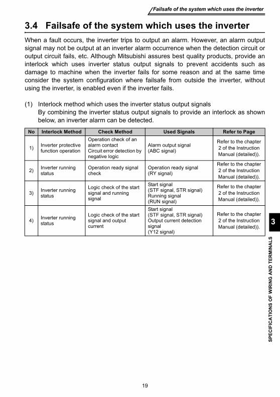
3.4 Failsafe of the system which uses the inverterWhen a fault occurs, the inverter trips to output an alarm. However, an alarm outputsignal may not be output at an inverter alarm occurrence when the detection circuit oroutput circuit fails, etc. Although Mitsubishi assures best quality products, provide aninterlock which uses inverter status output signals to prevent accidents such asdamage to machine when the inverter fails for some reason and at the same timeconsider the system configuration where failsafe from outside the inverter, withoutusing the inverter, is enabled even if the inverter fails.
(1) Interlock method which uses the inverter status output signals By combining the inverter status output signals to provide an interlock as shownbelow, an inverter alarm can be detected.
No Interlock Method Check Method Used Signals Refer to Page
1) Inverter protective function operation
Operation check of an alarm contactCircuit error detection by negative logic
Alarm output signal (ABC signal)
Refer to the chapter 2 of the Instruction Manual (detailed)).
2) Inverter running status
Operation ready signal check
Operation ready signal (RY signal)
Refer to the chapter 2 of the Instruction Manual (detailed)).
3) Inverter running status
Logic check of the start signal and running signal
Start signal (STF signal, STR signal)Running signal (RUN signal)
Refer to the chapter 2 of the Instruction Manual (detailed)).
4) Inverter running status
Logic check of the start signal and output current
Start signal (STF signal, STR signal)Output current detection signal (Y12 signal)
Refer to the chapter 2 of the Instruction Manual (detailed)).

Failsafe of the system which uses the inverter
20
(2) Backup method outside the inverterEven if the interlock is provided by the inverter status signal, enough failsafe isnot ensured depending on the failure status of the inverter itself. For example,even if the interlock is provided using the inverter alarm output signal, start signaland RUN signal output, there is a case where an alarm output signal is not outputand RUN signal is kept output even if an inverter alarm occurs.Provide a speed detector to detect the motor speed and current detector to detectthe motor current and consider the backup system such as checking up as belowaccording to the level of importance of the system.
1)Start signal and actual operation checkCheck the motor running and motor current while the start signal is input to theinverter by comparing the start signal to the inverter and detected speed of thespeed detector or detected current of the current detector. Note that the motorcurrent runs as the motor is running for the period until the motor stops since theinverter starts decelerating even if the start signal turns off. For the logic check,configure a sequence considering the inverter deceleration time. In addition, it isrecommended to check the three-phase current when using the current detector.
2)Command speed and actual operation checkCheck if there is no gap between the actual speed and commanded speed bycomparing the inverter speed command and detected speed of the speeddetector.
Inverter
Controller
System failure
To the alarm detection sensor
Sensor
(speed, temperature,
air volume, etc.)

21
Step of operation
4
DR
IVE
THE
MO
TOR
4. DRIVE THE MOTOR
4.1 Step of operationThe inverter needs frequency command and start command. Turning the startcommand on start the motor rotating and the motor speed is determined by thefrequency command.Refer to the flow chart below to perform setting.
CAUTIONCheck the following items before powering on the inverter.•Check that the inverter is installed correctly in a correct place. (Refer to page 6)•Check that wiring is correct. (Refer to page 7)•Check that no load is connected to the motor.
Step of operationof opStep of operation
Installation/mounting
System examination
Wiring of the powersupply and motor
Connect a switch, relay, etc.to the control circuit terminal block of the inverterto give a start command. (External)
Start command using the RS-485
connector of the inverter
(Communication)
Set from the operation panel.
(PU)
Change frequencywith ON/OFF switchesconnected to terminals(multi-speed setting)
Perform frequencysetting by a current output device(Connection acrossterminals 4-5)
Perform frequencysetting by a voltage output device(Connection acrossterminals 2-5)
Change of frequencywith ON/OFF switchesconnected to terminals(multi-speed setting)
Perform frequency setting by a currentoutput device(Connection acrossTerminals 4-5)
Perform frequency setting by a voltage output device(Connection acrossterminals 2-5)
(External) (External)
(PU)
How to give a frequency
command?
How to give a start
command?
- +RUN
Set from the operation panel
ON
Time(S)
Fre
qu
en
cy
(Hz)
Start command
Frequency command
Inverter outputfrequency
How to give a frequency
command?
(External)
(External) (External) (External)
Start command with
on the operation panel (PU)
Refer to Instruction Manual (detailed)
{Refer to page 24} {Refer to page 26} {Refer to page 28} {Refer to page 29}
{Refer to page 31} {Refer to page 33} {Refer to page 35} {Refer to page 37}
{Refer to page 6}
{Refer to page 9}
Run and operation
22
4.2 Run and operation
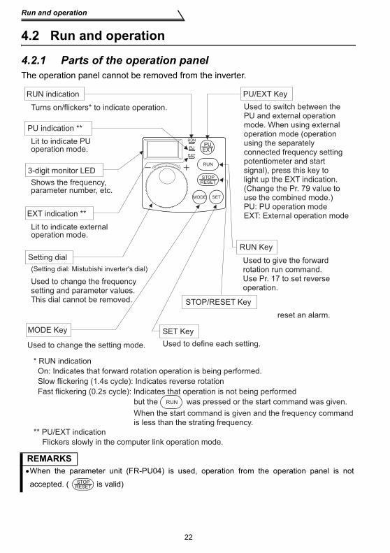
4.2.1 Parts of the operation panelThe operation panel cannot be removed from the inverter.
REMARKS•When the parameter unit (FR-PU04) is used, operation from the operation panel is not
accepted. ( is valid)
RUN
PUEXT
MODE SET
RUN
PU
EXT
STOPRESET
Used to change the setting mode.
RUN
RUN indication
PU indication **
Lit to indicate PU operation mode.
3-digit monitor LED
Shows the frequency, parameter number, etc.
EXT indication **
Lit to indicate externaloperation mode.
Setting dial
(Setting dial: Mistubishi inverter's dial)
Used to change the frequency setting and parameter values.This dial cannot be removed.
MODE Key SET Key
Used to define each setting.
When the start command is given and the frequency command
is less than the strating frequency.
reset an alarm.
STOP/RESET Key
Used to give the forward rotation run command. Use Pr. 17 to set reverse operation.
RUN Key
Used to switch between the PU and external operation mode. When using externaloperation mode (operation using the separately connected frequency setting potentiometer and start signal), press this key to light up the EXT indication. (Change the Pr. 79 value to use the combined mode.)PU: PU operation modeEXT: External operation mode
PU/EXT Key
Turns on/flickers* to indicate operation.
* RUN indication
On: Indicates that forward rotation operation is being performed.
Slow flickering (1.4s cycle): Indicates reverse rotation
Fast flickering (0.2s cycle): Indicates that operation is not being performed
but the was pressed or the start command was given.
** PU/EXT indication
Flickers slowly in the computer link operation mode.
STOPRESET
Run and operation
DR
IVE
THE
MO
TOR
23
4
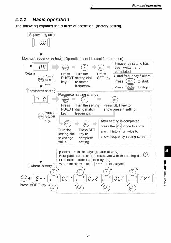
4.2.2 Basic operation The following explains the outline of operation. (factory setting)
Press to stop.Parameter setting
MODE
MODE
PUEXT
Press PU/EXT key.
Turn the setting dial to match frequency.
SET
Press SET key
[Operation panel is used for operation]
PUEXT
Press PU/EXT key.
Turn the setting dial to match frequency.
SET
Press SET key to show present setting.
[Parameter setting change]
Turn the setting dial to change value.
SET
Press SET key to complete setting.
RUNPress to start.
STOPRESET
Monitor/frequency setting
MODEPress MODE key.
Return
After setting is completed,
press the once to show
alarm history, or twice to
show frequency setting screen.
MODE
Press MODE key.
Press MODE key.
[Operation for displaying alarm history]Four past alarms can be displayed with the setting dial .(The latest alarm is ended by ".".)When no alarm exists, is displayed.
Alarm history
Frequency setting has been written and
completed!!
At powering on
and frequency flickers.
24
Operation by the start command from the operation panel (PU operation mode)
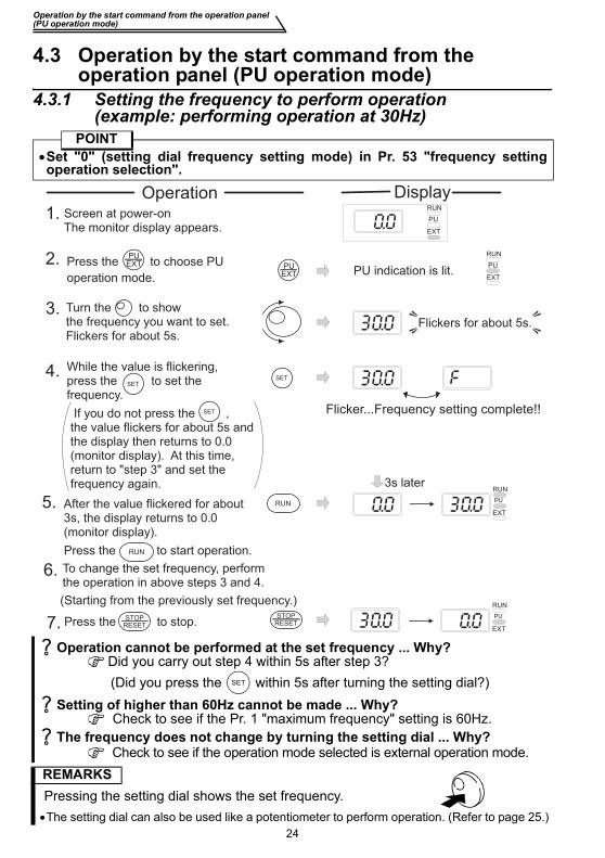
4.3 Operation by the start command from the operation panel (PU operation mode)
4.3.1 Setting the frequency to perform operation (example: performing operation at 30Hz)
POINT•Set "0" (setting dial frequency setting mode) in Pr. 53 "frequency settingoperation selection".
Operation cannot be performed at the set frequency ... Why? Did you carry out step 4 within 5s after step 3?(Did you press the within 5s after turning the setting dial?)
Setting of higher than 60Hz cannot be made ... Why? Check to see if the Pr. 1 "maximum frequency" setting is 60Hz.
The frequency does not change by turning the setting dial ... Why? Check to see if the operation mode selected is external operation mode.
REMARKS Pressing the setting dial shows the set frequency.•The setting dial can also be used like a potentiometer to perform operation. (Refer to page 25.)
1. Screen at power-onThe monitor display appears.
PUEXT
2. Press the to choose PU
operation mode.
PUEXT
Flicker...Frequency setting complete!!
SET
3. Turn the to show the frequency you want to set.Flickers for about 5s.
4.
5.
Press the to start operation.
6. To change the set frequency, perform the operation in above steps 3 and 4.
7.
RUN
Press the to stop.STOPRESET
SET
RUN
RUN
PU
EXT
RUN
PU
EXTPU indication is lit.
RUN
PU
EXT
While the value is flickering, press the to set the frequency.
After the value flickered for about 3s, the display returns to 0.0 (monitor display).
RUN
PU
EXT
3s later
Flickers for about 5s.
STOPRESET
SET If you do not press the , the value flickers for about 5s and the display then returns to 0.0 (monitor display). At this time, return to "step 3" and set the frequency again.
(Starting from the previously set frequency.)
DisplayOperation
SET
25
4
DR
IVE
THE
MO
TOR
Operation by the start command from the operation panel(PU operation mode)
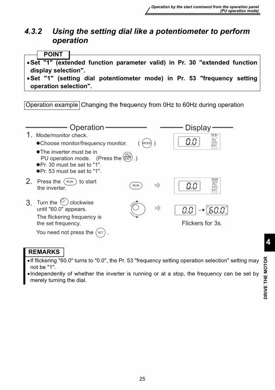
4.3.2 Using the setting dial like a potentiometer to perform operation
POINT•Set "1" (extended function parameter valid) in Pr. 30 "extended functiondisplay selection".•Set "1" (setting dial potentiometer mode) in Pr. 53 "frequency settingoperation selection".
Operation example Changing the frequency from 0Hz to 60Hz during operation
REMARKS•If flickering "60.0" turns to "0.0", the Pr. 53 "frequency setting operation selection" setting maynot be "1".•Independently of whether the inverter is running or at a stop, the frequency can be set bymerely turning the dial.
1.
�The inverter must be in PU operation mode.�Pr. 30 must be set to "1".�Pr. 53 must be set to "1".
(Press the .)
Mode/monitor check. RUN
PU
EXT�Choose monitor/frequency monitor. ( )
RUN
PU
EXT
RUN
3.
The flickering frequency is the set frequency.
You need not press the .
2. Press the to start the inverter.
RUN
Flickers for 3s.
MODE
PUEXT
SET
Operation Display
Turn the clockwise
until "60.0" appears.
Operation by the start command from the operation panel (PU operation mode)
26
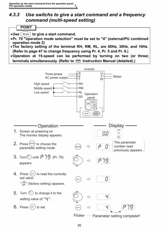
4.3.3 Use switchs to give a start command and a frequency command (multi-speed setting)
POINT
•Use to give a start command.•Pr. 79 "operation mode selection" must be set to "4" (external/PU combinedoperation mode 2)•The factory setting of the terminal RH, RM, RL, are 60Hz, 30Hz, and 10Hz.(Refer to page 47 to change frequency using Pr. 4, Pr. 5 and Pr. 6.)•Operation at 15-speed can be performed by turning on two (or three)terminals simultaneously. (Refer to Instruction Manual (detailed).)
RUN
Three-phase
AC power supply
SD
Inverter
RST
UVW
High speed
Middle speed
Low speed
RH
RM
RLOperation
panel
,RUNSTOP
RESET
Motor
1. Screen at powering on
The monitor display appears.
2. Press to choose the
parameter setting mode.
Flicker ・・・ Parameter setting complete!!
SET
3. Turn until (Pr. 79)
appears.
4.
5.
6.
RUN
PU
EXT
DisplayOperation
MODE
SET
The parameter
number read
previously appears.
MODE
Press to read the currently
set value.
SET
" " (factory setting) appears.
Turn to change it to the
setting value of " ".
Press to set.SET
Operation by the start command from the operation panel(PU operation mode)
4
DR
IVE
THE
MO
TOR
27
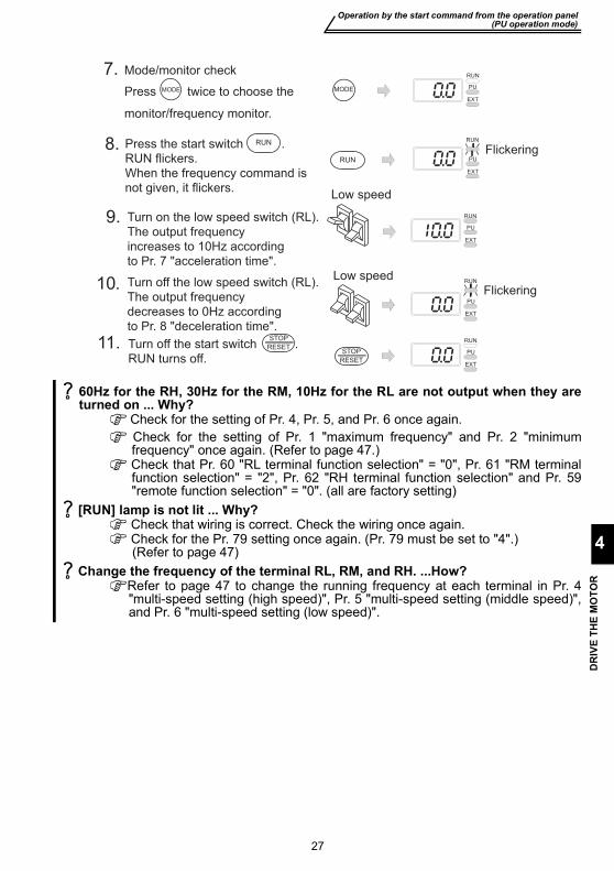
60Hz for the RH, 30Hz for the RM, 10Hz for the RL are not output when they areturned on ... Why?
Check for the setting of Pr. 4, Pr. 5, and Pr. 6 once again. Check for the setting of Pr. 1 "maximum frequency" and Pr. 2 "minimumfrequency" once again. (Refer to page 47.)
Check that Pr. 60 "RL terminal function selection" = "0", Pr. 61 "RM terminalfunction selection" = "2", Pr. 62 "RH terminal function selection" and Pr. 59"remote function selection" = "0". (all are factory setting)
[RUN] lamp is not lit ... Why? Check that wiring is correct. Check the wiring once again. Check for the Pr. 79 setting once again. (Pr. 79 must be set to "4".)
(Refer to page 47) Change the frequency of the terminal RL, RM, and RH. ...How?
Refer to page 47 to change the running frequency at each terminal in Pr. 4"multi-speed setting (high speed)", Pr. 5 "multi-speed setting (middle speed)",and Pr. 6 "multi-speed setting (low speed)".
Turn on the low speed switch (RL).
The output frequency
increases to 10Hz according
to Pr. 7 "acceleration time".
Turn off the low speed switch (RL).
The output frequency
decreases to 0Hz according
to Pr. 8 "deceleration time".
Low speed
Low speed
9.
10.
11. Turn off the start switch .
RUN turns off.
RUN
PU
EXT
PU
EXT
RUN
PU
EXT
STOP
RESET
RUN
Flickering
STOP
RESET
7.
Press twice to choose the
monitor/frequency monitor.
Mode/monitor check
MODE
Press the start switch .
RUN flickers.
When the frequency command is
not given, it flickers.
MODE
8.RUN
RUN
RUN
PU
EXT
RUN
PU
EXT
Flickering

28
Operation by the start command from the operation panel (PU operation mode)
4.3.4 Perform frequency setting by analog (voltage input)POINT
•Use to give a startcommand.•Pr. 79 "operation mode selection"must be set to "4" (external/PUcombined operation mode 2)
Change the frequency (60Hz) of the maximum value of potentiometer (at 5V)Adjust the frequency in Pr. 38 "frequency setting voltage gain frequency".(Refer to page 43)
Change the frequency (0Hz) of the minimum value of potentiometer (at 0V)Adjust the frequency in calibration parameter C2 "frequency setting voltagebias frequency". (Refer to Instruction Manual (detailed).)
Three-phase
AC power supply
10
5
MotorUVW
Inverter
R/L1S/L2
T/L3
2
[Connection diagram]
Operation
panel
,RUNSTOP
RESET
Frequency setting
potentiometer
RUN
Change the Pr. 79 setting to " ".
1. Screen at powering onThe monitor display appears.
2.
4.
5.
6.
7.
RUN
PU
EXT
DisplayOperation
Start
Press the start switch .
Operation status indication of RUN flickers.
RUN
Acceleration → constant speedTurn the potentiometer (frequency setting potentiometer) clockwise slowly to full. The frequency value on the indication increases according to Pr. 7 "acceleration time" until 60.00Hz is displayed.
DecelerationTurn the potentiometer (frequency setting potentiometer) counterclockwise slowly to full.The frequency value on the indication decreases according to Pr. 8 "deceleration time" until 0.00Hz is displayed and operation status indication of RUN flickers.The motor stops.
Stop
Press .Operation status indication of RUN turns off.
RUN PU
EXT
RUN
Flickering
RUN
PU
EXT
RUN
PU
EXT
PU
EXT
RUN
Flickering
STOP
RESET
STOP
RESET
Flicker ・・・ Parameter setting complete3.
Press twice to choose the
monitor/frequency monitor.
Mode/monitor checkMODE
MODE
RUN
PU
EXT
(Refer to page 26 for change of the setting.)
Operation by the start command from the operation panel(PU operation mode)
DR
IVE
THE
MO
TOR
29
4
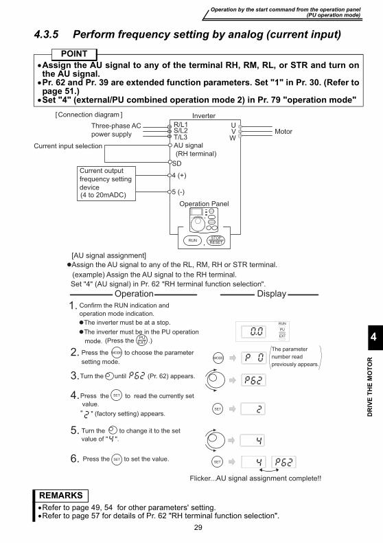
4.3.5 Perform frequency setting by analog (current input)POINT
•Assign the AU signal to any of the terminal RH, RM, RL, or STR and turn onthe AU signal.•Pr. 62 and Pr. 39 are extended function parameters. Set "1" in Pr. 30. (Refer topage 51.)•Set "4" (external/PU combined operation mode 2) in Pr. 79 "operation mode"
REMARKS•Refer to page 49, 54 for other parameters' setting.•Refer to page 57 for details of Pr. 62 "RH terminal function selection".
Three-phase AC
power supply
AU signal
(RH terminal)
MotorUV
W
Inverter
Current output
frequency setting
device(4 to 20mADC)
Current input selection
[Connection diagram ]
R/L1S/L2T/L3
Operation Panel
,RUNSTOP
RESET
SD
4 (+)
5 (-)
Assign the AU signal to any of the RL, RM, RH or STR terminal.
(example) Assign the AU signal to the RH terminal.
[AU signal assignment]
Set "4" (AU signal) in Pr. 62 "RH terminal function selection".
Confirm the RUN indication and
operation mode indication.
The inverter must be at a stop.
The inverter must be in the PU operation
mode.
MODE
Press the to choose the parameter
setting mode.
SET
SET
Turn the until (Pr. 62) appears.
Turn the to change it to the set
value of " ".
Press the to set the value.SET
RUN
PU
EXT
Flicker...AU signal assignment complete!!
Display Operation
PU(Press the .)
" (factory setting) appears."
The parameter
number read
previously appears.
Press the to read the currently set
value.
MODE2.
1.
3.
4.
5.
6.
EXT
SET
Operation by the start command from the operation panel (PU operation mode)
30
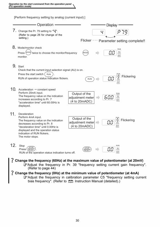
Change the frequency (60Hz) at the maximum value of potentiometer (at 20mV)Adjust the frequency in Pr. 39 "frequency setting current gain frequency".(Refer to page 44)
Change the frequency (0Hz) at the minimum value of potentiometer (at 4mA)Adjust the frequency in calibration parameter C5 "frequency setting currentbias frequency". (Refer to Instruction Manual (detailed).)
Output of the
adjustment meter
(4 to 20mADC)
Change the Pr. 79 setting to " ".
Display
[Perform frequency setting by analog (current input) ]
7.
9. Start
Check that the current input selection signal (AU) is on.
Press the start switch .
RUN of operation status indication flickers.
10.
11.
12.
Operation
Deceleration
Perform 4mA input.
The frequency value on the indication
decreases according to Pr. 8
"deceleration time" until 0.00Hz is
displayed and the operation status
indication of RUN flickers.
The motor stops.
Output of the
adjustment meter
(4 to 20mADC)
RUN
RUN
RUN
PU
EXT
Flickering
RUN
PU
EXT
RUN
PU
EXT
Flickering
Stop
Press .
RUN of the operation status indication turns off.
STOP
RESET
RUN
PU
EXT
STOP
RESET
Flicker ・・・ Parameter setting complete!!
8.Press twice to choose the monitor/frequency
monitor.
Mode/monitor check
MODE MODE
RUN
PU
EXT
Acceleration → constant speed
Perform 20mA input.
The frequency value on the indication
increases according to Pr. 7
"acceleration time" until 60.00Hz is
displayed.
(Refer to page 26 for change of thesetting.)
Operation by the start command of the terminal block(external operation)
DR
IVE
THE
MO
TOR
31
4
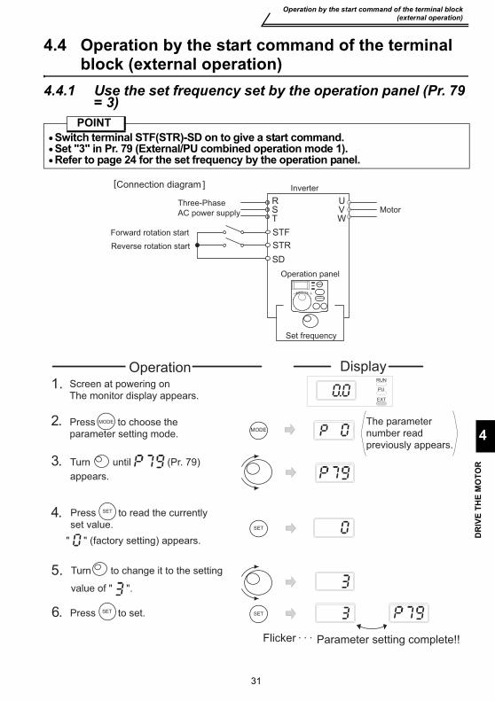
4.4 Operation by the start command of the terminal block (external operation)
4.4.1 Use the set frequency set by the operation panel (Pr. 79 = 3)
POINT•Switch terminal STF(STR)-SD on to give a start command.•Set "3" in Pr. 79 (External/PU combined operation mode 1).•Refer to page 24 for the set frequency by the operation panel.
[ ]
Three-Phase
AC power supply
SD
Inverter
RST
UVW
Forward rotation start
Reverse rotation start
STF
STR
Operation panel
Connection diagram
Motor
Set frequency
Turn to change it to the setting
value of " ".
Turn until (Pr. 79)
appears.
1. Screen at powering on
The monitor display appears.
2. Press to choose the
parameter setting mode.
Flicker・・・ Parameter setting complete!!
SET
3.
4.
5.
6.
RUN
PU
EXT
DisplayOperation
MODE
SET
MODE
Press to read the currently
set value.
SET
" " (factory setting) appears.
Press to set.SET
The parameter
number read
previously appears.

Operation by the start command of the terminal block (external operation)
32
REMARKS•To make a reverse rotation start, Pr. 63 "STR terminal function selection" must be set to "---".
(factory setting)•When Pr. 79 "operation mode selection" is set to "3", multi-speed operation (refer to page 33)
is also made valid.
When the inverter is stopped by of the operation panel,
are displayed alternately.
1. Turn the start switch (STF or STR) off.
2. The display can be reset by .
While the value is flickering,
press to set the frequency.
Turn the start switch (STF or
STR) off.
The motor decelerates according
to Pr. 8 "deceleration time" to stop.
10.
11.
8. Turn the start switch (STF or
STR) on.
Turn to change running frequency.
Display the frequency you want to set.
The frequency flickers for about 5s.
9.
RUN
PU
EXT
StopOFF
If you do not press , the value
flickers for about 5s and the display
then returns to 0.00 (display) Hz.
At this time, return to "Step 8" and
set the frequency again.
Forwardrotation
Reverserotation
ON
Flickers for about 5s
Forwardrotation Reverse
rotation
Flicker・・・ Parameter setting complete!!
SETSET
SET
7.
Press twice to choose the
monitor/frequency monitor.
Mode/monitor check
MODE MODE
RUN
PU
EXT
The motor runs at the frequency
set in the set frequency mode
of the operation panel.
STOPRESET
RUN
PU
EXT
Flickering
and
PUEXT
Operation by the start command of the terminal block(external operation)
4
DR
IVE
THE
MO
TOR
33
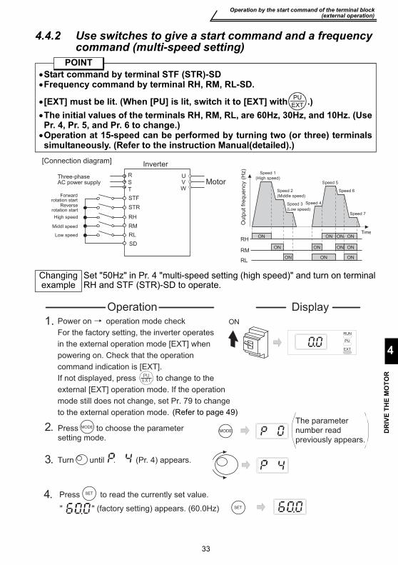
4.4.2 Use switches to give a start command and a frequency command (multi-speed setting)
POINT•Start command by terminal STF (STR)-SD•Frequency command by terminal RH, RM, RL-SD.
•[EXT] must be lit. (When [PU] is lit, switch it to [EXT] with .)•The initial values of the terminals RH, RM, RL, are 60Hz, 30Hz, and 10Hz. (UsePr. 4, Pr. 5, and Pr. 6 to change.)•Operation at 15-speed can be performed by turning two (or three) terminalssimultaneously. (Refer to the instruction Manual(detailed).)
Changing example
Set "50Hz" in Pr. 4 "multi-speed setting (high speed)" and turn on terminalRH and STF (STR)-SD to operate.
PUEXT
Three-phaseAC power supply
SD
Inverter
R
S
T
UVW
High speed
Forwardrotation start
Reverserotation start
Middl speed
Low speed
RH
RM
RL
STF
STR
ON
ON ON ON ON
ON ON
ONONON
ON
Speed 1
(High speed)
Speed 2
(Middle speed)
Speed 3
(Low speed)
Speed 4
Speed 5
Speed 6
Speed 7
Time
RH
RM
RL
[Connection diagram]
Motor
(Hz)
Ou
tpu
t fr
eq
ue
ncy
Turn until . (Pr. 4) appears.
1. Power on → operation mode check
For the factory setting, the inverter operates
in the external operation mode [EXT] when
powering on. Check that the operation
command indication is [EXT].
If not displayed, press to change to the
external [EXT] operation mode. If the operation
mode still does not change, set Pr. 79 to change
to the external operation mode.
2. Press to choose the parameter
setting mode.
3.
DisplayOperation
MODEMODE
RUN
PU
EXT
ON
4. Press to read the currently set value.SET
" " (factory setting) appears. (60.0Hz) SET
The parameter
number read
previously appears.
(Refer to page 49)

Operation by the start command of the terminal block (external operation)
34
[EXT] is not lit even when is pressed ...Why?
Switchover of the operation mode with is valid when Pr. 79 = "0" (initialvalue).
60Hz, 30Hz and 10Hz are not output from RH, RM and RL respectively when they areturned on. ...Why?
Check for the setting of Pr. 4, Pr. 5, and Pr. 6 once again. CHeck for the setting of Pr. 1 "maximum frequency" and Pr. 2 "minimumfrequency" once again. (Refer to page 47)
Check for the Pr. 79 setting once again. (Pr. 79 must be set to "0" or "2".) (Refer topage 47)
Check that Pr. 60 "RL termianl function selection" = "0", Pr. 61 "RM terminalfunction selection" = "1", Pr. 62 "RH termianl function selection" = "2" and Pr. 59"remote function selection" = "0". (factory setting)
[RUN] is not lit. ...Why? Check that wiring is correct. Check it again. To make a reverse rotation start, check that "---" is set in Pr. 63 "STR terminalfunction selection"? (factory setting)
How is the frequency setting from 4 to 7 speed? The setting differs according to Pr. 24 to Pr. 27 (multi-speed setting). Refer to Instruction Manual (detailed).
REMARKSExternal operation is fixed by setting "2" (external operation mode) in Pr. 79 "operation mode
selection" when you do not want to take time pressing or when you want to use thecurrent operation command and frequency command. (Refer to page 49)
Turn the start switch (STF or STR) on.
50Hz appears.
Stop
Turn the start switch (STF or STR) off.
The motor stops according to Pr. 8
"deceleration time".
9.
10.
RUN
PU
EXT
7. Mode/monitor check
Press twice to choose the
monitor/frequency monitor.
MODE
Turn on the high speed switch (RH).
MODE
8.
RUN
PU
EXT
ON
StopOFF
Forward rotationReverse rotation
ON
High speed
Middle speed
Low speed
Flicker ・・・ Parameter setting complete!!
5.
6. SET
Turn to change it to the seting
value of " ". (50.0Hz)
Press to set.SET
30Hz appears when RM is on and
10Hz appears when RL is on.
Forward rotationReverse rotation
PUEXT
PUEXT
PUEXT
Operation by the start command of the terminal block(external operation)
4
DR
IVE
THE
MO
TOR
35
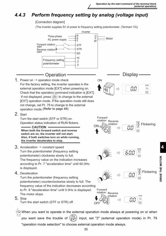
4.4.3 Perform frequency setting by analog (voltage input)
When you want to operate in the external operation mode always at powering on or when
you want save the trouble of input, set "2" (external operation mode) in Pr. 79
"operation mode selection" to choose external operation mode always.
Three-phase
AC power supply
SD
Inverter
RST
Forward rotationstartReverse rotationstart
STF
STR
[Connection diagram]
10
5
2Frequency setting
potentiometer
MotorUVW
(The inverter supplies 5V of power to frequency setting potentiometer. (Termianl 10))
Flickering
Forwardrotation Reverse
rotation
2..
3..
4.
5.
DisplayOperation
Acceleration → constant speed
Turn the potentiometer (frequency setting
potentiometer) clockwise slowly to full.
The frequency value on the indication increases
according to Pr. 7 "acceleration time" until 60.0Hz
is displayed.
Deceleration
Turn the potentiometer (frequency setting
potentiometer) counterclockwise slowly to full. The
frequency value of the indication decreases according
to Pr. 8 "deceleration time" until 0.0Hz is displayed.
The motor stops.
StopTurn the start switch (STF or STR) off.
PU
EXT
RUN
Flickering
Start
Turn the start switch (STF or STR) on.
Operation status indication of RUN flickers.
RUN
PU
EXT
RUN
PU
EXT
PU
EXT
RUN
Forwardrotation Reverse
rotationON
OFF
1. Power on → operation mode check
For the factory setting, the inverter operates in the
external operation mode [EXT] when powering on.
Check that the operation command indication is [EXT].
If not displayed, press to change to the external
[EXT] operation mode. If the operation mode still does
not change, set Pr. 79 to change to the external
operation mode.
RUN
PU
EXT
ON
CAUTIONWhen both the forward switch and reverse
switch are on, the inverter will not start.
Also, if both switches turn on while running,
the inverter decelerates to stop.
(Refer to page 49)
PUEXT
Operation by the start command of the terminal block (external operation)
36
REMARKSTo make a reverse rotation start, Pr. 63 "STR terminal function selection" must be set to "---".
The motor will not rotate ... Why? Check that [EXT] is lit.[EXT] is valid when Pr. 79 = "0" (factory setting).
Use to lit [EXT]. Check that wiring is correct. Check once again.
Change the frequency (60Hz) of the maximum value of potentiometer (at 5V) Adjust the frequency in Pr. 38 "frequency setting voltage gain frequency".(Refer to page 43)
Change the frequency (0Hz) of the minimum value of potentiometer (at 0V) Adjust the frequency in calibration parameter C2 "frequency setting Voltagebias frequency". (Refer to Instruction Manual (detailed).)
PUEXT
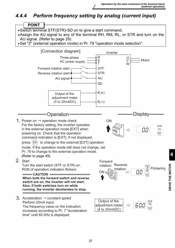
Operation by the start command of the terminal block(external operation)
4
DR
IVE
THE
MO
TOR
37
4.4.4 Perform frequency setting by analog (current input)
POINT•Switch terminal STF(STR)-SD on to give a start command.•Assign the AU signal to any of the terminal RH, RM, RL, or STR and turn on theAU signal. (Refer to page 29)•Set "2" (external operation mode) in Pr. 79 "operation mode selection".
Three-phase
AC power supply
SD
Inverter
RST
Forward rotation start
Reverse rotation start
STF
STR
AU signal AU
[Connection diagram]
MotorUVW
4
5(ー)
(+)Output of the
adjustment meter
(4 to 20mADC)
Power on → operation mode check
For the factory setting, the inverter operates
in the external operation mode [EXT] when
powering on. Check that the operation
command indication is [EXT]. If not displayed,
press to change to the external [EXT] operation
mode. If the operation mode still does not change, set
Pr. 79 to change to the external operation mode.
2.
3.
DisplayOperation
Acceleration → constant speed
Perform 20mA input.
The frequency value on the indication
increases according to Pr. 7 "acceleration
time" until 60.0Hz is displayed.
PU
EXT
RUN
Flickering
Start
Turn the start switch (STF or STR) on.
RUN of operation indication flickers.
RUN
PU
EXT
Forward
rotation Reverse
rotationON
1.RUN
PU
EXT
ON
CAUTIONWhen both the forward switch and reverse switch are on, the inverter will not start.Also, if both switches turn on while running, the inverter decelerates to stop.
Output of the
adjustment meter
(4 to 20mADC)
(Refer to page 49)
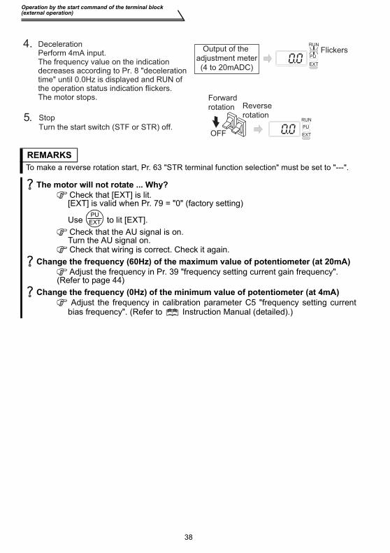
Operation by the start command of the terminal block (external operation)
38
REMARKSTo make a reverse rotation start, Pr. 63 "STR terminal function selection" must be set to "---".
The motor will not rotate ... Why? Check that [EXT] is lit.[EXT] is valid when Pr. 79 = "0" (factory setting)
Use to lit [EXT]. Check that the AU signal is on.Turn the AU signal on. Check that wiring is correct. Check it again.
Change the frequency (60Hz) of the maximum value of potentiometer (at 20mA) Adjust the frequency in Pr. 39 "frequency setting current gain frequency".
(Refer to page 44) Change the frequency (0Hz) of the minimum value of potentiometer (at 4mA)
Adjust the frequency in calibration parameter C5 "frequency setting currentbias frequency". (Refer to Instruction Manual (detailed).)
4.
5.
DecelerationPerform 4mA input.The frequency value on the indicationdecreases according to Pr. 8 "deceleration time" until 0.0Hz is displayed and RUN of the operation status indication flickers.The motor stops.
Stop
Turn the start switch (STF or STR) off.RUN
PU
EXT
PU
EXT
RUN
Flickers
Forward
rotation Reverse
rotation
OFF
Output of the
adjustment meter
(4 to 20mADC)
PUEXT
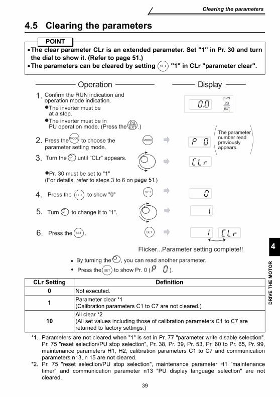
39
Clearing the parameters
4
DR
IVE
THE
MO
TOR
4.5 Clearing the parameters
*1. Parameters are not cleared when "1" is set in Pr. 77 "parameter write disable selection".Pr. 75 "reset selection/PU stop selection", Pr. 38, Pr. 39, Pr. 53, Pr. 60 to Pr. 65, Pr. 99,maintenance parameters H1, H2, calibration parameters C1 to C7 and communicationparameters n13, n 15 are not cleared.
*2. Pr. 75 "reset selection/PU stop selection", maintenance parameter H1 "maintenancetimer" and communication parameter n13 "PU display language selection" are notcleared.
POINT•The clear parameter CLr is an extended parameter. Set "1" in Pr. 30 and turnthe dial to show it. (Refer to page 51.)•The parameters can be cleared by setting "1" in CLr "parameter clear".
CLr Setting Definition0 Not executed.
1 Parameter clear *1(Calibration parameters C1 to C7 are not cleared.)
10All clear *2(All set values including those of calibration parameters C1 to C7 are returned to factory settings.)
SET
Turn the until "CLr" appears.
Press the to show Pr. 0 ( ).
3.
4. Press the to show "0"SET
5. Turn to change it to "1".
6. SETPress the .
1. Confirm the RUN indication andoperation mode indication.
The inverter must be at a stop.
The inverter must be in PU operation mode. (Press the .)
RUN
PU
EXT
2. Press the to choose the
parameter setting mode.
MODE
�Pr. 30 must be set to "1"(For details, refer to steps 3 to 6 on .)
MODE
SET
SET
Flicker...Parameter setting complete!!
The parameter number read previously appears.
By turning the , you can read another parameter.
SET
Operation Display
PUEXT
page 51
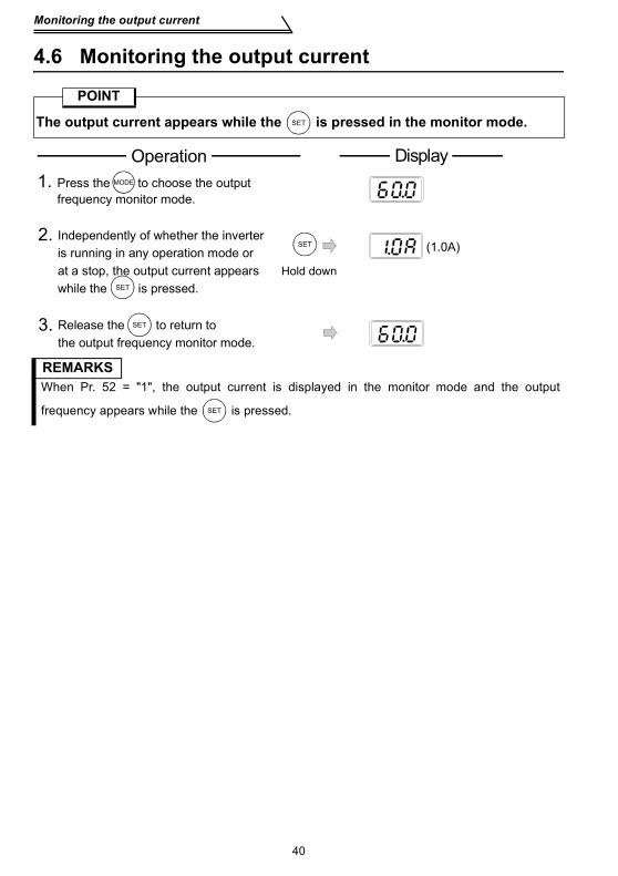
40
Monitoring the output current
4.6 Monitoring the output current
POINT
The output current appears while the is pressed in the monitor mode.
REMARKSWhen Pr. 52 = "1", the output current is displayed in the monitor mode and the output
frequency appears while the is pressed.
SET
2. Independently of whether the inverter is running in any operation mode or at a stop, the output current appears while the is pressed.
SET
Release the to return to the output frequency monitor mode.
3.
1. Press the to choose the output frequency monitor mode.
SET
SET
(1.0A)
MODE
Operation Display
Hold down
SET

AD
JUST
MEN
T O
F TH
E FR
EQU
ENC
Y SE
TTIN
G P
OTE
NTI
OM
ETER
AN
D IN
DIC
ATO
R
41
5
5. ADJUSTMENT OF THE FREQUENCY SETTING POTENTIOMETER AND INDICATOR
Related parameters
*1. Settings may differ because of calibration parameters.
*2. Pr. 73 "0-5V/0-10V selection" changes the specifications of terminal "2".
Parameter Name Setting Range Factory Setting38 Frequency setting voltage gain frequency 1 to 120Hz 60Hz39 Frequency setting current gain frequency 1 to 120Hz 60HzC2 Frequency setting voltage bias frequency 0 to 60Hz 0Hz C3 Frequency setting voltage bias 0 to 300% 0% *1C4 Frequency setting voltage gain 0 to 300% 96% *1C5 Frequency setting current bias frequency 0 to 60Hz 0HzC6 Frequency setting current bias 0 to 300% 20% *1C7 Frequency setting current gain 0 to 300% 100% *1
POINT•Bias setting for 0 to 5VDC (0 to 10VDC) input Use the calibration
parameter C2, C3 for setting•Gain setting for 0 to 5VDC (0 to 10VDC) input Use Pr. 38, calibration
parameter C4 for setting. •Bias setting for 4 to 20mADC input Use the calibration
parameter C5, C6 for setting.
•Gain setting for 4 to 20mADC input Use Pr. 39, calibration parameter C7 for setting.
For 4 to 20mADC input, set "4" in any of Pr. 60 to Pr. 63 (input terminalfunction selection) and assign AU (current input selection) to any of terminalsRH, RM, RL and STR, and turn on the AU signal.
C2
C3 (100% C4 ) C6 C7
Frequency setting voltage signal
Pr.38( )
0Hz( )
(0% )5V or 10V0V
Frequency setting current signal
Factory setting
(20% ) (100% )
20mA4mA
Pr.39
C5
( )
0Hz( )
terminals 2-5) terminals 4-5)
Factory setting
Outp
ut
frequency (
Hz)
Outp
ut
frequency (
Hz)
(Across (Across
Pr.73 *2
60Hz 60Hz
Changing the output frequency setting of the frequency setting potentiometer (bias and gain of frequency setting voltage (current))
42
5.1 Changing the output frequency setting of the frequency setting potentiometer(bias and gain of frequency setting voltage (current))
The bias/gain of the frequency setting voltage (current) may be adjusted in any of thefollowing methods:(1) Changing the highest frequency(2) Adjusting the deviation of the highest frequency from the Pr. 38 (Pr. 39) setting
(2)-1) Make adjustment with a voltage applied across terminals 2-5 (with a currentflowing across terminals 4-5)
(2)-2) Make adjustment at any point without a voltage applied across terminals 2-5(without a current flowing across terminals 4-5) (For the setting method, referto the instruction manual (detailed).)
POINTPr. 38, Pr. 39 and calibration parameters "C1 to C7" can be made to be read bysetting "1" (extended function parameter valid) in Pr. 30 "extended functiondisplay selection".

Changing the output frequency setting of the frequency settingpotentiometer (bias and gain of frequency setting voltage (current))
AD
JUST
MEN
T O
F TH
E FR
EQU
ENC
Y SE
TTIN
G P
OTE
NTI
OM
ETER
AN
D IN
DIC
ATO
R
43
5
(1) -1) Changing the highest frequency (0 to 5V input)
Changing example When you want to use the 0 to 5VDC input frequencysetting potentiometer to change the 5V-time frequencyfrom 60Hz (factory setting) to 50Hz.
POINT•Pr. 38 is an extended function parameter. Pr. 30 must be set to "1".(Refer to page 51.)•Change Pr. 38 "frequency setting voltage gain frequency" to 50Hz.
The monitor/frequency setting indication cannot be changed to just 50Hz ...Why?
The calibration parameter C4 "frequency setting voltage gain" value mustbe set. (Refer to page 45.)
REMARKSTo change the value to more than 60Hz, Pr. 1 "maximum frequency" must be set to more than60Hz.
3. Turn the until Pr. 38 "frequency
setting voltage gain frequency" appears.
4.
(Refer to steps 3 to 6 on
for the parameter setting method.)
SET
5.
2. MODE MODEPress the to choose the parameter
setting mode.
The parameter
number read
previously appears.
Pr. 30 must be set to "1"
6. Press the to set the value.
Flicker...Parameter setting complete!!
SET SET
RUN
PU
EXT
1. Confirm the RUN indication and operation
mode indication.
PUEXT
The inverter must be in the PU operation
mode.
By turning the , you can read another parameter.
SETPress the to show the setting again.
�
SETPress the twice to show the next parameter.�
�
�
The inverter must be at a stop.�
�
Operation Display
(Press the )
Press the to display the currently
set value. (60Hz)
SET
Turn the to change it to "50.0".
(50Hz)
page 51
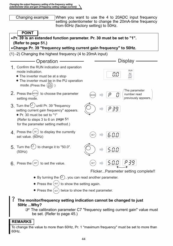
Changing the output frequency setting of the frequency setting potentiometer (bias and gain of frequency setting voltage (current))
44
(1) -2) Changing the highest frequency (4 to 20mA input)
Changing example When you want to use the 4 to 20ADC input frequencysetting potentiometer to change the 20mA-time frequencyfrom 60Hz (factory setting) to 50Hz.
POINT•Pr. 39 is an extended function parameter. Pr. 30 must be set to "1".(Refer to page 51.)•Change Pr. 39 "frequency setting current gain frequency" to 50Hz.
The monitor/frequency setting indication cannot be changed to just 50Hz ...Why?
The calibration parameter C7 "frequency setting current gain" value mustbe set. (Refer to page 45.)
REMARKSTo change the value to more than 60Hz, Pr. 1 "maximum frequency" must be set to more than60Hz.
By turning the , you can read another parameter.
(Press the )
Turn the
Press the to choose the parameter
Press the to set the value.
Press the twice to show the next parameter.
Press the to show the setting again.
3. until Pr. 39 "frequency
setting current gain frequency" appears.
4.
(Refer to steps 3 to 6 on
for the parameter setting method.)
SET
5.
2. MODEMODE
setting mode.
Pr. 30 must be set to "1"
6.
Flicker...Parameter setting complete!!
SET SET
RUN
PU
EXT
1. Confirm the RUN indication and operation
mode indication.
PUEXT
The inverter must be in the PU operation
mode.
SET
�
SET�
�
�
The inverter must be at a stop.
�
�
Operation
Press the to display the currently
set value. (60Hz)
SET
Turn the to change it to "50.0".
(50Hz)
Display
The parameter
number read
previously appears.
page 51
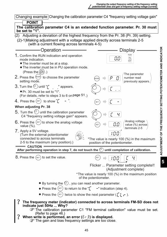
Changing the output frequency setting of the frequency settingpotentiometer (bias and gain of frequency setting voltage (current))
AD
JUST
MEN
T O
F TH
E FR
EQU
ENC
Y SE
TTIN
G P
OTE
NTI
OM
ETER
AN
D IN
DIC
ATO
R
45
5
(2) Adjusting a deviation of the highest frequency from the Pr. 38 (Pr. 39) setting.(2)-1)Making adjustment with a voltage applied directly across terminals 2-5
(with a current flowing across terminals 4-5)
Changing example Changing the calibration parameter C4 "frequency setting voltage gain"POINT
The calibration parameter C4 is an extended function parameter. Pr. 30 mustbe set to "1".
The frequency meter (indicator) connected to across terminals FM-SD does notindicate just 50Hz ... Why?
The calibration parameter C1 "FM terminal calibration" value must be set.(Refer to page 46.)
When write is performed, an error ( ) is displayed. The gain and bias frequency settings are too close.
Turn the until " " appears.
OperationRUN
PU
EXT
1.
PUEXT(Press the .)
Confirm the RUN indication and operationmode indication.
The inverter must be at a stop.The inverter must be in PU operation mode.
3.
MODE2. MODE
SET4. SETPress the
7.12
34
5 6
7
8
9
10
*
*The value is nearly 100 (%) in the maximum position of the potentiometer.
8. Press the to set the value.SET SET*
Flicker ... Parameter setting complete!!
5. Turn the until the calibration parameter C4 "frequency setting voltage gain" appears.
6. SET
SET
Analog voltage value (%) across terminals 2-5
Press the to show the analog voltage value (%).
(Adjustment complete)
*The value is nearly 100 (%) in the maximum position of the potentiometer.
Apply a 5V voltage.(Turn the external potentiometerconnected to across terminals2-5 to the maximum (any position).)
Press the to choose the parameter setting mode.
By turning the , you can read another parameter.
SETPress the to return to the " " indication (step 4).
SETPress the twice to show the next parameter ( ).
(For details, refer to steps 3 to 6 on .)Pr. 30 must be set to "1".
to show ." "
When adjusting Pr. 38
After performing operation in step 7, do not touch the until completion of calibration.
�
�
�
CAUTION
Display
The parameter
number read
previously appears.
page 51
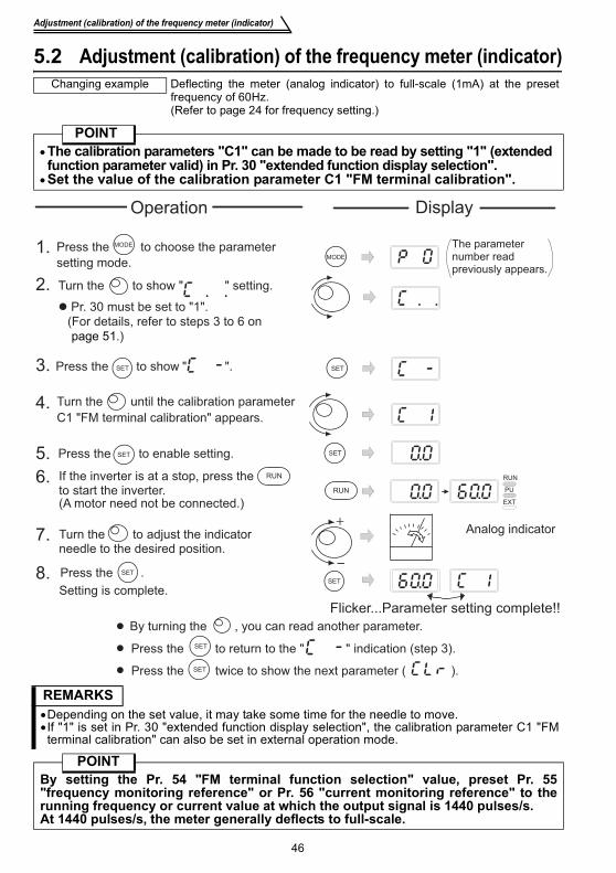
46
Adjustment (calibration) of the frequency meter (indicator)
5.2 Adjustment (calibration) of the frequency meter (indicator)Changing example Deflecting the meter (analog indicator) to full-scale (1mA) at the preset
frequency of 60Hz.(Refer to page 24 for frequency setting.)
POINT•The calibration parameters "C1" can be made to be read by setting "1" (extendedfunction parameter valid) in Pr. 30 "extended function display selection".
•Set the value of the calibration parameter C1 "FM terminal calibration".
REMARKS•Depending on the set value, it may take some time for the needle to move.•If "1" is set in Pr. 30 "extended function display selection", the calibration parameter C1 "FMterminal calibration" can also be set in external operation mode.
POINTBy setting the Pr. 54 "FM terminal function selection" value, preset Pr. 55"frequency monitoring reference" or Pr. 56 "current monitoring reference" to therunning frequency or current value at which the output signal is 1440 pulses/s.At 1440 pulses/s, the meter generally deflects to full-scale.
By turning the , you can read another parameter.
Press the to return to the " " indication (step 3).
Press the twice to show the next parameter ( ).
1.
2.
3.
8.
7.
6.
5.
4.
Press the to choose the parameter
setting mode.MODE
Press the to enable setting. SETSET
SET
SET
Turn the to show " " setting.
Press the to show " ".SET
MODE
SET
Press the .
Flicker...Parameter setting complete!!
Setting is complete.
If the inverter is at a stop, press theto start the inverter.(A motor need not be connected.)
RUN
PU
EXT
RUN
RUN
Turn the to adjust the indicator needle to the desired position.
� Pr. 30 must be set to "1".
(For details, refer to steps 3 to 6 on
.)
The parameter number read previously appears.
Analog indicator
Operation
SET
SET
�
�
�
Display
Turn the until the calibration parameter
C1 "FM terminal calibration" appears.
page 51

Basic function parameter list
FUN
CTI
ON
LIS
T
47
6
6. FUNCTION LIST6.1 Basic function parameter list
* The factory setting varies with the inverter capacity: 5% for FR-S540E-1.5K and 2.2K, 4% forFR-S540E-3.7K.
Parameter Name Indication Setting
RangeMinimum Setting
IncrementsFactory Setting
Customer Setting
0 Torque boost 0 to 15% 0.1% 6%/5%/4% *
1 Maximum frequency 0 to 120Hz 0.1Hz 60Hz
2 Minimum frequency 0 to 120Hz 0.1Hz 0Hz
3 Base frequency 0 to 120Hz 0.1Hz 60Hz
4 Multi-speed set-ting (high speed) 0 to 120Hz 0.1Hz 60Hz
5 Multi-speed set-ting (middle speed) 0 to 120Hz 0.1Hz 30Hz
6 Multi-speed set-ting (low speed) 0 to 120Hz 0.1Hz 10Hz
7 Acceleration time 0 to 999s 0.1s 5s
8 Deceleration time 0 to 999s 0.1s 5s
9 Electronic thermal O/L relay 0 to 50A 0.1A Inverter rated
current
30 Extended function display selection 0, 1 1 0
79 Operation mode selection 0 to 4, 7, 8 1 0
REMARKS•Setting "1" in Pr. 30 "extended function display selection" makes the extended functionparameters valid. (Refer to page 51.)•The decimal places of a value of 100 or more (3 digits or more) cannot be set to be displayed.
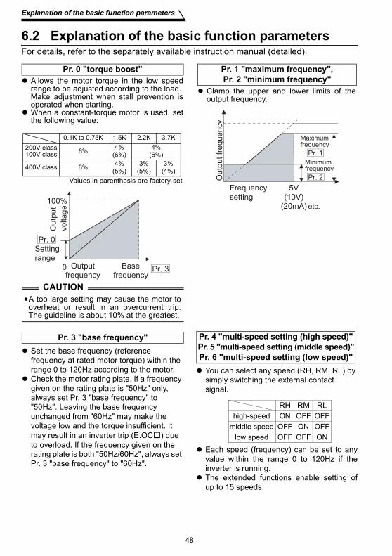
Explanation of the basic function parameters
48
6.2 Explanation of the basic function parametersFor details, refer to the separately available instruction manual (detailed).
Allows the motor torque in the low speedrange to be adjusted according to the load.Make adjustment when stall prevention isoperated when starting.When a constant-torque motor is used, setthe following value:
Pr. 0 "torque boost"
CAUTION•A too large setting may cause the motor tooverheat or result in an overcurrent trip.The guideline is about 10% at the greatest.
Values in parenthesis are factory-set
0.1K to 0.75K 1.5K 2.2K 3.7K200V class100V class 6% 4%
(6%)4%
(6%)
400V class 6% 4%(5%)
3%(5%)
3%(4%)
Setting range
Base frequency
0
100%
Output frequency
Pr. 0
Pr. 3
Outp
ut
voltage
Clamp the upper and lower limits of theoutput frequency.
Pr. 1 "maximum frequency", Pr. 2 "minimum frequency"
Pr. 1
Pr. 2
Frequency setting
Minimum frequency
Maximum frequency
Outp
ut fr
equ
en
cy
5V(10V)
(20mA) etc.
Set the base frequency (reference frequency at rated motor torque) within the range 0 to 120Hz according to the motor.Check the motor rating plate. If a frequency given on the rating plate is "50Hz" only, always set Pr. 3 "base frequency" to "50Hz". Leaving the base frequency unchanged from "60Hz" may make the voltage low and the torque insufficient. It may result in an inverter trip (E.OC ) due to overload. If the frequency given on the rating plate is both "50Hz/60Hz", always set Pr. 3 "base frequency" to "60Hz".
Pr. 3 "base frequency"
You can select any speed (RH, RM, RL) by simply switching the external contact signal.
Each speed (frequency) can be set to anyvalue within the range 0 to 120Hz if theinverter is running.The extended functions enable setting ofup to 15 speeds.
Pr. 4 "multi-speed setting (high speed)"Pr. 5 "multi-speed setting (middle speed)"Pr. 6 "multi-speed setting (low speed)"
RH RM RLhigh-speed
middle speedlow speed
OFF OFFOFF
OFF OFFOFFON
ONON
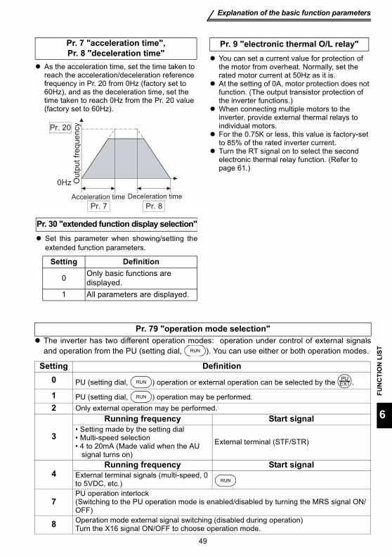
Explanation of the basic function parameters
FUN
CTI
ON
LIS
T
49
6
The inverter has two different operation modes: operation under control of external signalsand operation from the PU (setting dial, ). You can use either or both operation modes.
Pr. 79 "operation mode selection"
Setting Definition0 PU (setting dial, ) operation or external operation can be selected by the .
1 PU (setting dial, ) operation may be performed. 2 Only external operation may be performed.
3
Running frequency Start signal• Setting made by the setting dial• Multi-speed selection• 4 to 20mA (Made valid when the AU signal turns on)
External terminal (STF/STR)
4Running frequency Start signal
External terminal signals (multi-speed, 0 to 5VDC, etc.)
7PU operation interlock(Switching to the PU operation mode is enabled/disabled by turning the MRS signal ON/OFF)
8 Operation mode external signal switching (disabled during operation)Turn the X16 signal ON/OFF to choose operation mode.
As the acceleration time, set the time taken to reach the acceleration/deceleration reference frequency in Pr. 20 from 0Hz (factory set to 60Hz), and as the deceleration time, set the time taken to reach 0Hz from the Pr. 20 value (factory set to 60Hz).
Pr. 7 "acceleration time", Pr. 8 "deceleration time"
Acceleration time Deceleration time
Pr. 20
Pr. 7 Pr. 8
0Hz Outp
ut
freq
ue
ncy
You can set a current value for protection of the motor from overheat. Normally, set the rated motor current at 50Hz as it is.At the setting of 0A, motor protection does not function. (The output transistor protection of the inverter functions.)When connecting multiple motors to the inverter, provide external thermal relays to individual motors.For the 0.75K or less, this value is factory-set to 85% of the rated inverter current.Turn the RT signal on to select the second electronic thermal relay function. (Refer to page 61.)
Pr. 9 "electronic thermal O/L relay"
Set this parameter when showing/setting theextended function parameters.
Pr. 30 "extended function display selection"
Setting Definition
0 Only basic functions are displayed.
1 All parameters are displayed.
RUN
RUNPU
EXT
RUN
RUN
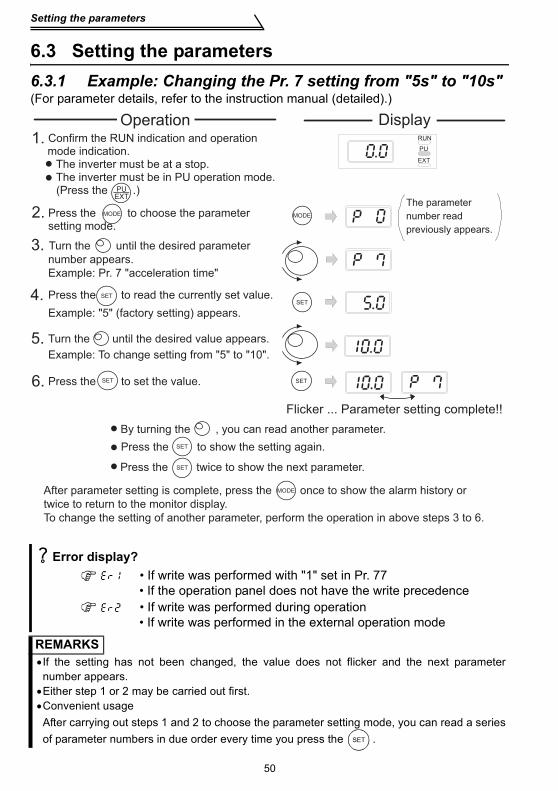
50
Setting the parameters
6.3 Setting the parameters6.3.1 Example: Changing the Pr. 7 setting from "5s" to "10s"(For parameter details, refer to the instruction manual (detailed).)
Error display? • If write was performed with "1" set in Pr. 77
• If the operation panel does not have the write precedence • If write was performed during operation
• If write was performed in the external operation mode
REMARKS•If the setting has not been changed, the value does not flicker and the next parameternumber appears.•Either step 1 or 2 may be carried out first.•Convenient usageAfter carrying out steps 1 and 2 to choose the parameter setting mode, you can read a seriesof parameter numbers in due order every time you press the .
After parameter setting is complete, press the once to show the alarm history or
twice to return to the monitor display.
To change the setting of another parameter, perform the operation in above steps 3 to 6.
1. Confirm the RUN indication and operation mode indication.
The inverter must be at a stop.The inverter must be in PU operation mode.
2. Press the to choose the parameter setting mode.
MODEMODE
PUEXT
SET
SET
3. Turn the until the desired parameter
number appears.
Example: Pr. 7 "acceleration time"
5. Turn the until the desired value appears.
Example: To change setting from "5" to "10".
4. SET
6. Press the to set the value.SET
MODE
RUN
PU
EXT
Flicker ... Parameter setting complete!!
By turning the , you can read another parameter.
SETPress the to show the setting again.
SETPress the twice to show the next parameter.
(Press the .)The parameter
number read
previously appears.
Press the to read the currently set value.
Example: "5" (factory setting) appears.
�
�
Operation Display
�
�
�
SET
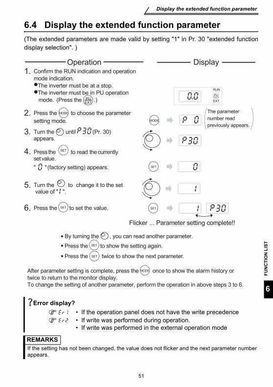
51
Display the extended function parameter
FUN
CTI
ON
LIS
T
6
6.4 Display the extended function parameter(The extended parameters are made valid by setting "1" in Pr. 30 "extended functiondisplay selection". )
Error display? • If the operation panel does not have the write precedence • If write was performed during operation.
• If write was performed in the external operation mode
REMARKSIf the setting has not been changed, the value does not flicker and the next parameter numberappears.
After parameter setting is complete, press the once to show the alarm history or
twice to return to the monitor display.
To change the setting of another parameter, perform the operation in above steps 3 to 6.
1. Confirm the RUN indication and operation
mode indication.�The inverter must be at a stop.�The inverter must be in PU operation
mode.
2.MODE
Press the to choose the parameter
setting mode.
SET
SET
3. Turn the until (Pr. 30) appears.
5. Turn the to change it to the set value of " ".
4. SET
6. Press the to set the value.SET
MODE
RUN
PU
EXT
Flicker ... Parameter setting complete!!
By turning the , you can read another parameter.
SETPress the to show the setting again.
Press the twice to show the next parameter.
PUEXT
(Press the .)
" (factory setting) appears."
The parameter
number read
previously appears.
Press the to read the currently set value.
MODE
SET
•
•
•
Operation Display

Extended function parameter list
52
6.5 Extended function parameter listSetting "1" in Pr. 30 "extended function display selection" makes the extended functionparameters valid. (Refer to the separately available instruction manual (detailed).)
Parameter Name Description Factory SettingIndication
For parameters 0 to 9, refer to the basic function parameters. (page 47.)
10 DC injection brake operation frequency
Set the timing of switching to DC injection brake (0 to 120Hz), the time to apply DC injection brake (0 to 10s), and the braking torque at DC injection brake start (0 to 15%). (Set Pr. 12 to 4% when a constant-torque motor is used.)
3Hz
11 DC injection brake operation time 0.5s
12 DC injection brake voltage 6%
13 Starting frequency
Frequency which is output by the inverter first at a start and gives great influence to the starting torque. About 1 to 3Hz for vertical lift applications, or up to 5Hz to the maximum. For other than vertical lift applications, factory setting of about 0.5Hz is recommended.0 to 60Hz
0.5Hz
14 Load pattern selection
Choose the output frequency and output voltage patterns according to the application (load characteristic).0: For constant-torque loads (when
relatively large torque is needed at low to high speeds)
1: For variable-torque loads (for applications where torque is small at low speed, e.g. fans and pumps)
2: For vertical lifts(for elevators at reverse rotation boost of 0%)
3: For vertical lifts(for elevators at forward rotation boost of 0%)
0
15 Jog frequencySpeed command (0 to 120Hz) and acceleration/deceleration slope (0 to 999s) for jog (inching) operationWhen the FR-PU04 is connected, these parameters can be read as the basic parameters.
5Hz
16 Jog acceleration/deceleration time 0.5s
17 RUN key rotation direction selection
The of the operation panel can be used to choose the direction of rotation for operation.0: Forward rotation, 1: Reverse rotation
0
RUN
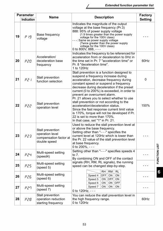
Extended function parameter list
FUN
CTI
ON
LIS
T
53
6
19 Base frequency voltage
Indicates the magnitude of the output voltage at the base frequency (Pr.3)888: 95% of power supply voltage
(1.9 times greater than the power supply voltage for the 100V class)
- - -: Same as power supply voltage(Twice greater than the power supply voltage for the 100V class)
0 to 800V, 888, - - -
- - -
20Acceleration/deceleration base frequency
Indicates the frequency to be referenced for acceleration from or deceleration to 0Hz in the time set in Pr. 7 "acceleration time" or Pr. 8 "deceleration time".1 to 120Hz
60Hz
21 Stall prevention function selection
Stall prevention is a function designed to suspend a frequency increase during acceleration, decrease frequency during constant speed or suspend a frequency decrease during deceleration if the preset current (0 to 200%) is exceeded, in order to prevent an overcurrent alarm.Pr. 21 allows you to select whether to use stall prevention or not according to the acceleration/deceleration status.Since the fast response current limit value is 170%, torque will not be developed if Pr. 22 is set to more than 170%.In that case, set "1" in Pr. 21.
0
22 Stall prevention operation level 150%
23Stall prevention operation level compensation factor at double speed
Used to reduce the stall prevention level at or above the base frequency.Setting other than "- - -" specifies the current level at 120Hz which is lower than the Pr. 22 value of the stall prevention level at base frequency.0 to 200%, - - -
- - -
24 Multi-speed setting (speed4)
Setting other than "- - -" specifies speeds 4 to 7.By combining ON and OFF of the contact signals (RH, RM, RL signals), the running speed can be changed step-by-step.
0 to 120Hz, - - -
- - -
25 Multi-speed setting (speed 5) - - -
26 Multi-speed setting (speed 6) - - -
27 Multi-speed setting (speed 7) - - -
28Stall prevention operation reduction starting frequency
You can reduce the stall prevention level in the high frequency range.0 to 120Hz
60Hz
Parameter Name Description Factory SettingIndication
RH RM RLON ON
ON
ONONONON ONON
Speed 4Speed 5Speed 6Speed 7
OFFOFF
OFF
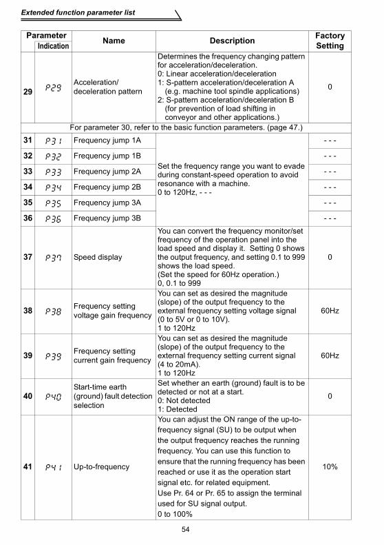
Extended function parameter list
54
29
Acceleration/deceleration pattern
Determines the frequency changing pattern for acceleration/deceleration.0: Linear acceleration/deceleration1: S-pattern acceleration/deceleration A
(e.g. machine tool spindle applications)2: S-pattern acceleration/deceleration B
(for prevention of load shifting in conveyor and other applications.)
0
For parameter 30, refer to the basic function parameters. (page 47.)
31 Frequency jump 1A
Set the frequency range you want to evade during constant-speed operation to avoid resonance with a machine.0 to 120Hz, - - -
- - -
32 Frequency jump 1B - - -
33 Frequency jump 2A - - -
34 Frequency jump 2B - - -
35 Frequency jump 3A - - -
36 Frequency jump 3B - - -
37 Speed display
You can convert the frequency monitor/set frequency of the operation panel into the load speed and display it. Setting 0 shows the output frequency, and setting 0.1 to 999 shows the load speed.(Set the speed for 60Hz operation.)0, 0.1 to 999
0
38 Frequency setting voltage gain frequency
You can set as desired the magnitude (slope) of the output frequency to the external frequency setting voltage signal (0 to 5V or 0 to 10V).1 to 120Hz
60Hz
39 Frequency setting current gain frequency
You can set as desired the magnitude (slope) of the output frequency to the external frequency setting current signal (4 to 20mA).1 to 120Hz
60Hz
40Start-time earth (ground) fault detection selection
Set whether an earth (ground) fault is to be detected or not at a start.0: Not detected1: Detected
0
41 Up-to-frequency
You can adjust the ON range of the up-to-frequency signal (SU) to be output when the output frequency reaches the running frequency. You can use this function to ensure that the running frequency has been reached or use it as the operation start signal etc. for related equipment.Use Pr. 64 or Pr. 65 to assign the terminal used for SU signal output.0 to 100%
10%
Parameter Name Description Factory SettingIndication
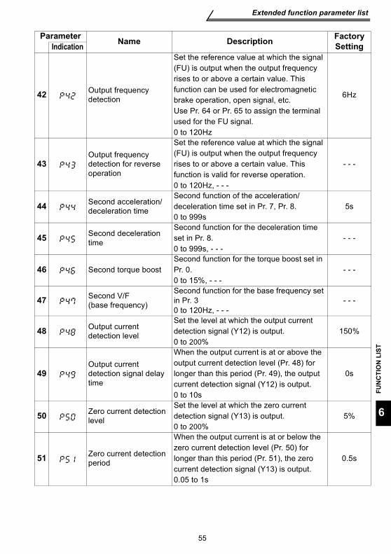
Extended function parameter list
FUN
CTI
ON
LIS
T
55
6
42 Output frequency detection
Set the reference value at which the signal (FU) is output when the output frequency rises to or above a certain value. This function can be used for electromagnetic brake operation, open signal, etc.Use Pr. 64 or Pr. 65 to assign the terminal used for the FU signal.0 to 120Hz
6Hz
43Output frequency detection for reverse operation
Set the reference value at which the signal (FU) is output when the output frequency rises to or above a certain value. This function is valid for reverse operation.0 to 120Hz, - - -
- - -
44 Second acceleration/deceleration time
Second function of the acceleration/deceleration time set in Pr. 7, Pr. 8.0 to 999s
5s
45 Second deceleration time
Second function for the deceleration time set in Pr. 8.0 to 999s, - - -
- - -
46 Second torque boostSecond function for the torque boost set in Pr. 0.0 to 15%, - - -
- - -
47 Second V/F (base frequency)
Second function for the base frequency set in Pr. 30 to 120Hz, - - -
- - -
48 Output current detection level
Set the level at which the output current detection signal (Y12) is output.0 to 200%
150%
49Output current detection signal delay time
When the output current is at or above the output current detection level (Pr. 48) for longer than this period (Pr. 49), the output current detection signal (Y12) is output.0 to 10s
0s
50 Zero current detection level
Set the level at which the zero current detection signal (Y13) is output.0 to 200%
5%
51 Zero current detection period
When the output current is at or below the zero current detection level (Pr. 50) for longer than this period (Pr. 51), the zero current detection signal (Y13) is output.0.05 to 1s
0.5s
Parameter Name Description Factory SettingIndication
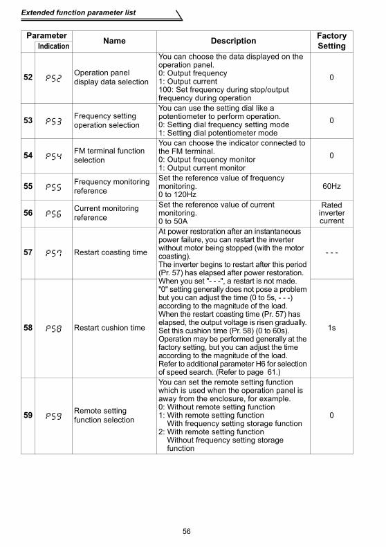
Extended function parameter list
56
52 Operation panel display data selection
You can choose the data displayed on the operation panel.0: Output frequency1: Output current100: Set frequency during stop/output frequency during operation
0
53 Frequency setting operation selection
You can use the setting dial like a potentiometer to perform operation.0: Setting dial frequency setting mode1: Setting dial potentiometer mode
0
54 FM terminal function selection
You can choose the indicator connected to the FM terminal.0: Output frequency monitor1: Output current monitor
0
55 Frequency monitoring reference
Set the reference value of frequency monitoring.0 to 120Hz
60Hz
56 Current monitoring reference
Set the reference value of current monitoring.0 to 50A
Rated inverter current
57 Restart coasting time
At power restoration after an instantaneous power failure, you can restart the inverter without motor being stopped (with the motor coasting).The inverter begins to restart after this period (Pr. 57) has elapsed after power restoration.When you set "- - -", a restart is not made. "0" setting generally does not pose a problem but you can adjust the time (0 to 5s, - - -) according to the magnitude of the load.When the restart coasting time (Pr. 57) has elapsed, the output voltage is risen gradually. Set this cushion time (Pr. 58) (0 to 60s).Operation may be performed generally at the factory setting, but you can adjust the time according to the magnitude of the load.Refer to additional parameter H6 for selection of speed search. (Refer to page 61.)
- - -
58 Restart cushion time 1s
59 Remote setting function selection
You can set the remote setting function which is used when the operation panel is away from the enclosure, for example.0: Without remote setting function1: With remote setting function With frequency setting storage function2: With remote setting function Without frequency setting storage function
0
Parameter Name Description Factory SettingIndication
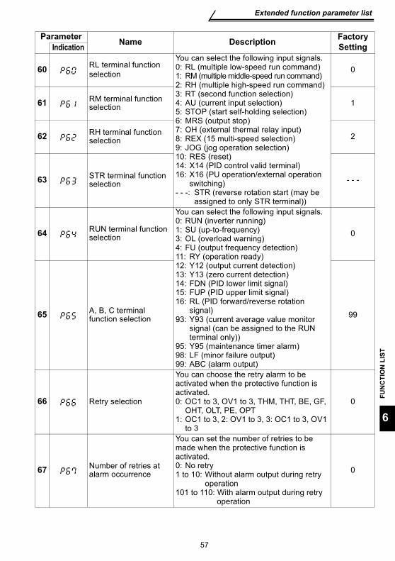
Extended function parameter list
FUN
CTI
ON
LIS
T
57
6
60 RL terminal function selection
You can select the following input signals.0: RL (multiple low-speed run command)1: RM (multiple middle-speed run command)2: RH (multiple high-speed run command)3: RT (second function selection)4: AU (current input selection)5: STOP (start self-holding selection)6: MRS (output stop)7: OH (external thermal relay input)8: REX (15 multi-speed selection)9: JOG (jog operation selection)10: RES (reset)14: X14 (PID control valid terminal)16: X16 (PU operation/external operation
switching)- - -: STR (reverse rotation start (may be
assigned to only STR terminal))
0
61 RM terminal function selection 1
62 RH terminal function selection 2
63 STR terminal function selection - - -
64 RUN terminal function selection
You can select the following input signals.0: RUN (inverter running)1: SU (up-to-frequency)3: OL (overload warning)4: FU (output frequency detection)11: RY (operation ready)12: Y12 (output current detection)13: Y13 (zero current detection)14: FDN (PID lower limit signal)15: FUP (PID upper limit signal)16: RL (PID forward/reverse rotation
signal)93: Y93 (current average value monitor
signal (can be assigned to the RUN terminal only))
95: Y95 (maintenance timer alarm)98: LF (minor failure output)99: ABC (alarm output)
0
65 A, B, C terminal function selection 99
66 Retry selection
You can choose the retry alarm to be activated when the protective function is activated.0: OC1 to 3, OV1 to 3, THM, THT, BE, GF,
OHT, OLT, PE, OPT1: OC1 to 3, 2: OV1 to 3, 3: OC1 to 3, OV1
to 3
0
67 Number of retries at alarm occurrence
You can set the number of retries to be made when the protective function is activated.0: No retry1 to 10: Without alarm output during retry
operation101 to 110: With alarm output during retry
operation
0
Parameter Name Description Factory SettingIndication
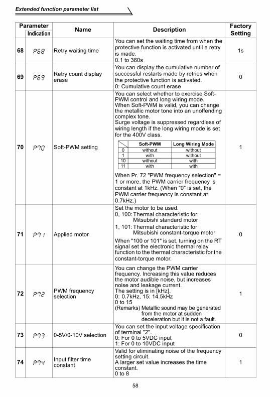
Extended function parameter list
58
68 Retry waiting time
You can set the waiting time from when the protective function is activated until a retry is made.0.1 to 360s
1s
69 Retry count display erase
You can display the cumulative number of successful restarts made by retries when the protective function is activated.0: Cumulative count erase
0
70 Soft-PWM setting
You can select whether to exercise Soft-PWM control and long wiring mode.When Soft-PWM is valid, you can change the metallic motor tone into an unoffending complex tone.Surge voltage is suppressed regardless of wiring length if the long wiring mode is set for the 400V class.
When Pr. 72 "PWM frequency selection" = 1 or more, the PWM carrier frequency is constant at 1kHz. (When "0" is set, the PWM carrier frequency is constant at 0.7kHz.)
1
71 Applied motor
Set the motor to be used.0, 100:
1, 101:0
72 PWM frequency selection
You can change the PWM carrier frequency. Increasing this value reduces the motor audible noise, but increases noise and leakage current.The setting is in [kHz].0: 0.7kHz, 15: 14.5kHz0 to 15(Remarks) Metallic sound may be generated
from the motor at sudden deceleration but it is not a fault.
1
73 0-5V/0-10V selectionYou can set the input voltage specification of terminal "2".0: For 0 to 5VDC input1: For 0 to 10VDC input
0
74 Input filter time constant
Valid for eliminating noise of the frequency setting circuit.A larger set value increases the time constant.0 to 8
1
Parameter Name Description Factory SettingIndication
Soft-PWM Long Wiring Mode0 without without1 with without
10 without with11 with with
Thermal characteristic for Mitsubishi standard motorThermal characteristic for Mitsubishi constant-torque motor
When "100 or 101" is set, turning on the RT signal set the electronic thermal relay function to the thermal characteristic for the constant-torque motor.
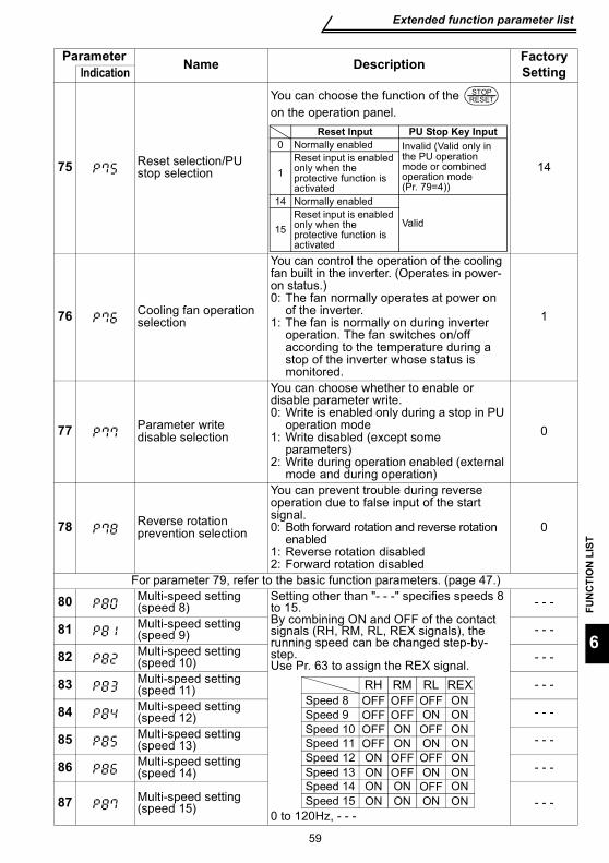
Extended function parameter list
FUN
CTI
ON
LIS
T
59
6
75 Reset selection/PU stop selection
You can choose the function of the on the operation panel.
14
76 Cooling fan operation selection
You can control the operation of the cooling fan built in the inverter. (Operates in power-on status.)0: The fan normally operates at power on
of the inverter.1: The fan is normally on during inverter
operation. The fan switches on/off according to the temperature during a stop of the inverter whose status is monitored.
1
77 Parameter write disable selection
You can choose whether to enable or disable parameter write.0: Write is enabled only during a stop in PU
operation mode1: Write disabled (except some
parameters)2: Write during operation enabled (external
mode and during operation)
0
78 Reverse rotation prevention selection
You can prevent trouble during reverse operation due to false input of the start signal.0: Both forward rotation and reverse rotation
enabled1: Reverse rotation disabled2: Forward rotation disabled
0
For parameter 79, refer to the basic function parameters. (page 47.)
80 Multi-speed setting (speed 8)
Setting other than "- - -" specifies speeds 8 to 15.By combining ON and OFF of the contact signals (RH, RM, RL, REX signals), the running speed can be changed step-by-step.Use Pr. 63 to assign the REX signal.
0 to 120Hz, - - -
- - -
81 Multi-speed setting (speed 9) - - -
82 Multi-speed setting (speed 10) - - -
83 Multi-speed setting (speed 11) - - -
84 Multi-speed setting (speed 12) - - -
85 Multi-speed setting (speed 13) - - -
86 Multi-speed setting (speed 14) - - -
87 Multi-speed setting (speed 15) - - -
Parameter Name Description Factory SettingIndication
STOPRESET
Reset Input PU Stop Key Input0 Normally enabled Invalid (Valid only in
the PU operation mode or combined operation mode (Pr. 79=4))
1Reset input is enabled only when the protective function is activated
14 Normally enabled
Valid15Reset input is enabled only when the protective function is activated
RH RM RL
ON
ONONON
REX
ON
ONONONON ONON
ONONONONONONONON
ON
Speed 8Speed 9Speed 10Speed 11Speed 12Speed 13Speed 14Speed 15
OFFOFFOFFOFF OFF OFF
OFF
OFFOFF
OFF
OFF
OFF
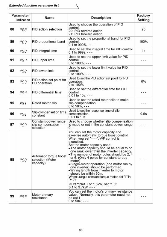
Extended function parameter list
60
88 PID action selectionUsed to choose the operation of PID control.20: PID reverse action, 21: PID forward action
20
89 PID proportional bandUsed to set the proportional band for PID control.0.1 to 999%, - - -
100%
90 PID integral time Used to set the integral time for PID control.0.1 to 999s, - - - 1s
91 PID upper limitUsed to set the upper limit value for PID control.0 to 100%, - - -
- - -
92 PID lower limitUsed to set the lower limit value for PID control.0 to 100%, - - -
- - -
93 PID action set point for PU operation
Used to set the PID action set point for PU operation.0 to 100%
0%
94 PID differential timeUsed to set the differential time for PID control.0.01 to 10s, - - -
- - -
95 Rated motor slipUsed to set the rated motor slip to make slip compensation.0 to 50%, - - -
- - -
96 Slip compensation time constant
Used to set the response time of slip compensation.0.01 to 10s
0.5s
97Constant-power range slip compensation selection
Used to choose whether slip compensation is made or not in the constant-power range.0, - - -
- - -
98 Automatic torque boost selection (Motor capacity)
You can set the motor capacity and exercise automatic torque boost control.When you set "- - -", V/F control is exercised. Set the motor capacity used.•The motor capacity should be equal to or one rank lower than the inverter capacity.•The number of motor poles should be 2, 4 or 6. (Only 4 poles for constant-torque motor)•Single-motor operation (one motor run by one inverter) should be performed.•Wiring length from inverter to motor should be within 30m.
When using a constant-torque motor, set "1" in Pr. 71.
- - -
99 Motor primary resistance
You can set the motor's primary resistance value. (Normally, this parameter need not be set.)0 to 50Ω, - - -
- - -
Parameter Name Description Factory SettingIndication
<Example> For 1.5kW, set "1.5".0.1 to 3.7kW, - - -
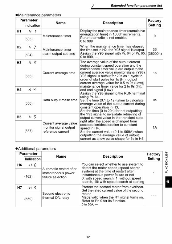
Extended function parameter list
FUN
CTI
ON
LIS
T
61
6
Maintenance parameters
Additional parameters
ParameterName Description Factory
SettingIndicationH1
Maintenance timerDisplay the maintenance timer (cumulative energization time) in 1000h increments. Parameter write is not enabled.0 to 999
0(503)
H2Maintenance timer alarm output set time
When the maintenance timer has elapsed the time set in H2, the Y95 signal is output. Assign the Y95 signal with Pr. 64 or Pr. 65.0 to 999, ---
36(36000h)(504)
H3
Current average time
The average value of the output current during constant speed operation and the maintenance timer value are output to the current average value monitor signal (Y93).Y93 signal is output for 20s as 1 cycle in order of start pulse for 1s (Hi), output current average value for 0.5 to 9s (Low), maintenance timer value for 2 to 9s (Hi), and end signal (Low).Assign the Y93 signal to the RUN terminal using Pr. 64.Set the time (0.1 to 1s) taken to calculate average value of the output current during constant operation in H3.Set the time (0 to 20s) for not outputting the Y93 signal to invalidate retrieving of output current value in the transient state right after the speed is changed from acceleration/deceleration to constant speed in H4.Set the current value (0.1 to 999A) when outputting the average value of output current as a low pulse shape for 5s in H5.
1s(555)
H4
Data output mask time 0s(556)
H5Current average value monitor signal output reference current
1A(557)
ParameterName Description Factory
SettingIndicationH6
Automatic restart after instantaneous power failure selection
You can select whether to use system to detect the motor speed (speed search system) at the time of restart after instantaneous power failure or not0: with speed search, 1: without speed search, 10: with speed search at starting
1(162)
H7Second electronic thermal O/L relay
Protect the second motor from overheat.Set the rated current value of the second motor.Made valid when the RT signal turns on.Refer to Pr. 9 for its function.0 to 50A, ---
- - -(559)
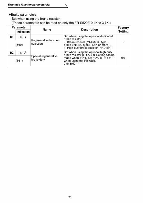
Extended function parameter list
62
Brake parametersSet when using the brake resistor.(These parameters can be read on only the FR-S520E-0.4K to 3.7K.)Parameter
Name Description Factory SettingIndication
b1Regenerative function selection
Set when using the optional dedicated brake resistor.0: Brake resistor (MRS/MYS type), brake unit (BU type) (1.5K or more)1: High-duty brake resistor (FR-ABR)
0(560)
b2Special regenerative brake duty
Set when using the optional high-duty brake resistor (FR-ABR). Setting can be made when b1=1. Set 10% in Pr. 561 when using the FR-ABR.0 to 30%
0%(561)
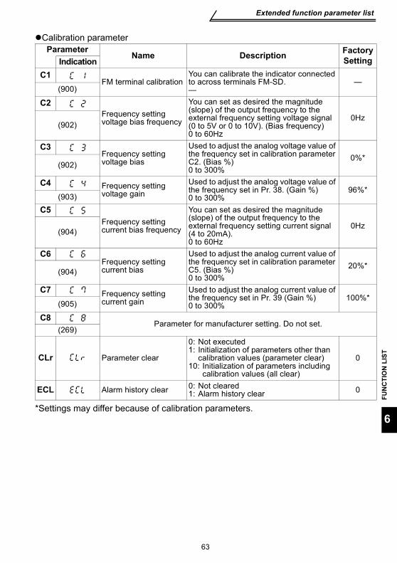
Extended function parameter list
FUN
CTI
ON
LIS
T
63
6
Calibration parameter
*Settings may differ because of calibration parameters.
ParameterName Description Factory
SettingIndicationC1
FM terminal calibrationYou can calibrate the indicator connected to across terminals FM-SD.—
—(900)
C2Frequency setting voltage bias frequency
You can set as desired the magnitude (slope) of the output frequency to the external frequency setting voltage signal (0 to 5V or 0 to 10V). (Bias frequency)0 to 60Hz
0Hz(902)
C3Frequency setting voltage bias
Used to adjust the analog voltage value of the frequency set in calibration parameter C2. (Bias %)0 to 300%
0%*(902)
C4 Frequency setting voltage gain
Used to adjust the analog voltage value of the frequency set in Pr. 38. (Gain %)0 to 300%
96%*(903)
C5Frequency setting current bias frequency
You can set as desired the magnitude (slope) of the output frequency to the external frequency setting current signal (4 to 20mA).0 to 60Hz
0Hz(904)
C6Frequency setting current bias
Used to adjust the analog current value of the frequency set in calibration parameter C5. (Bias %)0 to 300%
20%*(904)
C7 Frequency setting current gain
Used to adjust the analog current value of the frequency set in Pr. 39 (Gain %)0 to 300%
100%*(905)
C8Parameter for manufacturer setting. Do not set.
(269)
CLr Parameter clear
0: Not executed1: Initialization of parameters other than
calibration values (parameter clear)10: Initialization of parameters including
calibration values (all clear)
0
ECL Alarm history clear 0: Not cleared1: Alarm history clear 0
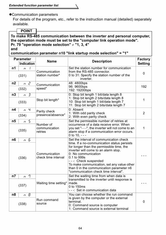
Extended function parameter list
64
Communication parametersFor details of the program, etc., refer to the instruction manual (detailed) separatelyavailable.
POINTTo make RS-485 communication between the inverter and personal computer,the operation mode must be set to the "computer link operation mode".Pr. 79 "operation mode selection" ≠ "1, 3, 4"andcommunication parameter n10 "link startup mode selection" = "1"
Parameter Name Description Factory SettingIndication
n1Communication station number*
Set the station number for communication from the RS-485 connector.0 to 31: Specify the station number of the
inverter.0
(331)
n2 Communication speed*
48: 4800bps96: 9600bps192: 19200bps
192(332)
n3Stop bit length*
0: Stop bit length 1 bit/data length 81: Stop bit length 2 bits/data length 810: Stop bit length 1 bit/data length 711: Stop bit length 2 bits/data length 7
1(333)
n4 Parity check presence/absence*
0: Absent1: With odd parity check2: With even parity check
2(334)
n5Number of communication retries
Set the permissible number of retries at occurrence of a data receive error. When you set "- - -", the inverter will not come to an alarm stop if a communication error occurs.0 to 10, - - -
1(335)
n6
Communication check time interval
Set the interval of communication check time. If a no-communication status persists for longer than the permissible time, the inverter will come to an alarm stop.0: No communication0.1 to 999s- - -: Check suspendedTo make communication, set any value other than 0 in the communication parameter n6 "communication check time interval".
- - -(336)
n7
Waiting time setting*
Set the waiting time from when data is transmitted to the inverter until response is made.0 to 150ms- - -: Set in communication data
- - -(337)
n8Run command source
You can choose whether the run command is given by the computer or the external terminal.0: Command source is computer1: Command source is external terminal
0(338)
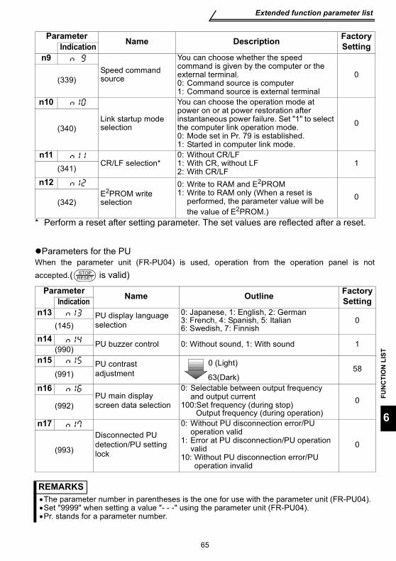
Extended function parameter list
FUN
CTI
ON
LIS
T
65
6
* Perform a reset after setting parameter. The set values are reflected after a reset.
Parameters for the PUWhen the parameter unit (FR-PU04) is used, operation from the operation panel is notaccepted.( is valid)
n9Speed command source
You can choose whether the speed command is given by the computer or the external terminal.0: Command source is computer1: Command source is external terminal
0(339)
n10
Link startup mode selection
You can choose the operation mode at power on or at power restoration after instantaneous power failure. Set "1" to select the computer link operation mode.0: Mode set in Pr. 79 is established.1: Started in computer link mode.
0(340)
n11CR/LF selection*
0: Without CR/LF1: With CR, without LF2: With CR/LF
1(341)
n12E2PROM write selection
0: Write to RAM and E2PROM1: Write to RAM only (When a reset is
performed, the parameter value will be the value of E2PROM.)
0(342)
Parameter Name Outline Factory SettingIndication
n13 PU display language selection
0: Japanese, 1: English, 2: German3: French, 4: Spanish, 5: Italian6: Swedish, 7: Finnish
0(145)
n14 PU buzzer control 0: Without sound, 1: With sound 1(990)
n15 PU contrast adjustment 58
(991)
n16PU main display screen data selection
0: Selectable between output frequency and output current
100:Set frequency (during stop)Output frequency (during operation)
0(992)
n17Disconnected PU detection/PU setting lock
0: Without PU disconnection error/PU operation valid
1: Error at PU disconnection/PU operation valid
10: Without PU disconnection error/PU operation invalid
0(993)
REMARKS•The parameter number in parentheses is the one for use with the parameter unit (FR-PU04).•Set "9999" when setting a value "- - -" using the parameter unit (FR-PU04).•Pr. stands for a parameter number.
Parameter Name Description Factory SettingIndication
STOPRESET
63(Dark)
0 (Light)
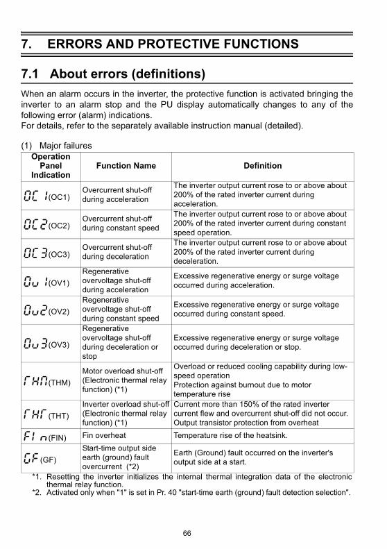
About errors (definitions)
66
7. ERRORS AND PROTECTIVE FUNCTIONS
7.1 About errors (definitions)When an alarm occurs in the inverter, the protective function is activated bringing theinverter to an alarm stop and the PU display automatically changes to any of thefollowing error (alarm) indications.For details, refer to the separately available instruction manual (detailed).
(1) Major failuresOperation
Panel Indication
Function Name Definition
(OC1)Overcurrent shut-off during acceleration
The inverter output current rose to or above about 200% of the rated inverter current during acceleration.
(OC2)Overcurrent shut-off during constant speed
The inverter output current rose to or above about 200% of the rated inverter current during constant speed operation.
(OC3)Overcurrent shut-off during deceleration
The inverter output current rose to or above about 200% of the rated inverter current during deceleration.
(OV1)Regenerative overvoltage shut-off during acceleration
Excessive regenerative energy or surge voltage occurred during acceleration.
(OV2)Regenerative overvoltage shut-off during constant speed
Excessive regenerative energy or surge voltage occurred during constant speed.
(OV3)
Regenerative overvoltage shut-off during deceleration or stop
Excessive regenerative energy or surge voltage occurred during deceleration or stop.
(THM)Motor overload shut-off(Electronic thermal relay function) (*1)
Overload or reduced cooling capability during low-speed operationProtection against burnout due to motor temperature rise
(THT)Inverter overload shut-off(Electronic thermal relay function) (*1)
Current more than 150% of the rated inverter current flew and overcurrent shut-off did not occur.Output transistor protection from overheat
(FIN) Fin overheat Temperature rise of the heatsink.
(GF)Start-time output side earth (ground) fault overcurrent (*2)
Earth (Ground) fault occurred on the inverter's output side at a start.
*1. Resetting the inverter initializes the internal thermal integration data of the electronicthermal relay function.
*2. Activated only when "1" is set in Pr. 40 "start-time earth (ground) fault detection selection".

About errors (definitions)
ERR
OR
S A
ND
PR
OTE
CTI
VE F
UN
CTI
ON
S
67
7
*3. Activated only when any of Pr. 60 to Pr. 63 (input terminal function selection) is set to OH.
(2) Minor failures
(OHT)External thermal relay (*3)
External thermal relay provided for protection from overheat was actuated (contact open).
(OLT)Stall prevention (overload)
Stall prevention was activated to drop the running frequency to 0. (OL appears while stall prevention is activated.)
(BE) Brake transistor alarmError occurred in the brake circuit, e.g. damaged brake transistors. (can be connected to the FR-S520E-0.4K to 3.7K only)
(OPT) Communication error
• Communication errors occurred consecutively more than the permissible number of retries when the RS-485 connector is used and communication parameter n5 ≠ "- - -".
• RS-485 communication error occurred.• Communication has broken for a period set in
communication parameter n6.
(PE)Parameter storage device alarm Error occurred in the parameter stored.
(PUE) PU disconnected PU was disconnected when communication parameter n17 = "1".
(RET) Retry count over Operation could not be resumed properly within the preset number of retries.
(CPU) CPU error Arithmetic operation of the built-in CPU does not end within the predetermined time.
Operation Panel
IndicationFunction Name Definition
(FN) Fan trouble The cooling fan built in the inverter failed (stopped).
Operation Panel
IndicationFunction Name Definition
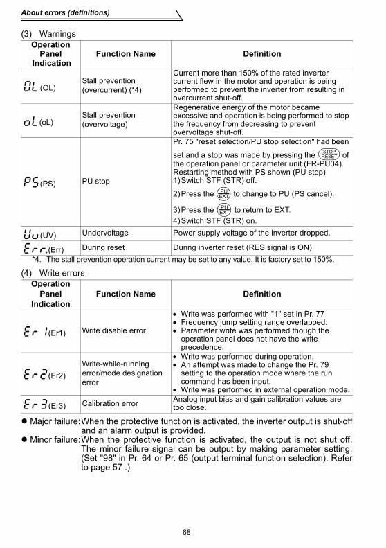
About errors (definitions)
68
(3) Warnings
(4) Write errors
Major failure:When the protective function is activated, the inverter output is shut-offand an alarm output is provided.
Minor failure:When the protective function is activated, the output is not shut off.The minor failure signal can be output by making parameter setting.(Set "98" in Pr. 64 or Pr. 65 (output terminal function selection). Referto page 57 .)
Operation Panel
IndicationFunction Name Definition
(OL)Stall prevention (overcurrent) (*4)
Current more than 150% of the rated inverter current flew in the motor and operation is being performed to prevent the inverter from resulting in overcurrent shut-off.
(oL)Stall prevention (overvoltage)
Regenerative energy of the motor became excessive and operation is being performed to stop the frequency from decreasing to prevent overvoltage shut-off.
(PS) PU stop
Pr. 75 "reset selection/PU stop selection" had been
set and a stop was made by pressing the of the operation panel or parameter unit (FR-PU04).Restarting method with PS shown (PU stop)1)Switch STF (STR) off.
2)Press the to change to PU (PS cancel).
3)Press the to return to EXT.4)Switch STF (STR) on.
(UV) Undervoltage Power supply voltage of the inverter dropped.
(Err) During reset During inverter reset (RES signal is ON)*4. The stall prevention operation current may be set to any value. It is factory set to 150%.
Operation Panel
IndicationFunction Name Definition
(Er1) Write disable error
• Write was performed with "1" set in Pr. 77• Frequency jump setting range overlapped.• Parameter write was performed though the
operation panel does not have the write precedence.
(Er2)Write-while-running error/mode designation error
• Write was performed during operation.• An attempt was made to change the Pr. 79
setting to the operation mode where the run command has been input.
• Write was performed in external operation mode.
(Er3) Calibration error Analog input bias and gain calibration values are too close.
STOPRESET
PUEXT
PUEXT
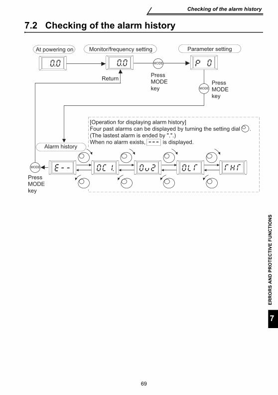
69
Checking of the alarm history
ERR
OR
S A
ND
PR
OTE
CTI
VE F
UN
CTI
ON
S
7
7.2 Checking of the alarm history
Press
MODE
key
Press
MODE
key
Parameter setting
MODE
MODE
MODE
Press
MODE
key
Return
[Operation for displaying alarm history]
Four past alarms can be displayed by turning the setting dial .
(The lastest alarm is ended by ".".)
When no alarm exists, is displayed. Alarm history
At powering on Monitor/frequency setting
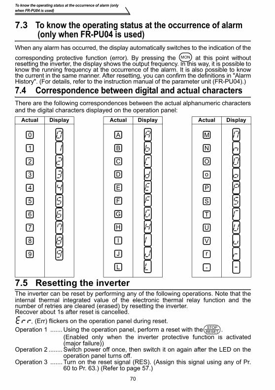
70
To know the operating status at the occurrence of alarm (only when FR-PU04 is used)
7.3 To know the operating status at the occurrence of alarm (only when FR-PU04 is used)
When any alarm has occurred, the display automatically switches to the indication of thecorresponding protective function (error). By pressing the at this point withoutresetting the inverter, the display shows the output frequency. In this way, it is possible toknow the running frequency at the occurrence of the alarm. It is also possible to knowthe current in the same manner. After resetting, you can confirm the definitions in "AlarmHistory". (For details, refer to the instruction manual of the parameter unit (FR-PU04).)7.4 Correspondence between digital and actual charactersThere are the following correspondences between the actual alphanumeric charactersand the digital characters displayed on the operation panel:
7.5 Resetting the inverterThe inverter can be reset by performing any of the following operations. Note that theinternal thermal integrated value of the electronic thermal relay function and thenumber of retries are cleared (erased) by resetting the inverter.Recover about 1s after reset is cancelled.
(Err) flickers on the operation panel during reset.Operation 1 ....... Using the operation panel, perform a reset with the .
(Enabled only when the inverter protective function is activated(major failure))
Operation 2 ........ Switch power off once, then switch it on again after the LED on theoperation panel turns off.
Operation 3 ....... Turn on the reset signal (RES). (Assign this signal using any of Pr.60 to Pr. 63.) (Refer to page 57.)
Actual Display Actual Display Actual Display
MON
0
1
2
3
4
5
6
7
8
9
A
B
C
D
E
F
G
H
I
J
L
M
N
O
P
T
U
V
r
-
S
o
STOPRESET

Troubleshooting
ERR
OR
S A
ND
PR
OTE
CTI
VE F
UN
CTI
ON
S
71
7
7.6 TroubleshootingPOINTS
If the cause is still unknown after every check, it is recommended to initialize theparameters (return to factory setting) then reset the required parameter values andcheck again.
7.6.1 Motor remains stopped
1) Check the main circuit
Check that a proper power supply voltage is applied (operation paneldisplay is provided).Check that the motor is connected properly.Check that the jumper across P-P1 is connected.
2) Check the input signals
Check that the start signal is input.Check that both the forward and reverse rotation start signals are notinput simultaneously.Check that the frequency setting signal is not zero.Check that the AU signal is on when the frequency setting signal is 4 to20mA.Check that the output stop signal (MRS) or reset signal (RES) is not on.(Assign signals MRS and RES using Pr. 60 to Pr. 63 (input terminalfunction selection).)Check that the sink or source jumper connector is fitted securely.
3) Check the parameter settingsCheck that the reverse rotation prevention (Pr. 78) is not selected.Check that the operation mode (Pr. 79) setting is correct.Check that the bias and gain (C2 to C7) settings are correct.Check that the starting frequency (Pr. 13) setting is not greater than therunning frequency.Check that various operational functions (such as three-speed operation),especially the maximum frequency (Pr. 1), are not zero.
4) Check the load
Check that the load is not too heavy.Check that the shaft is not locked.
5) OthersCheck that the operation panel display does not show an error (e.g. OC1).Check that the Pr. 15 "jog frequency" setting is not lower than the Pr. 13"starting frequency" value.
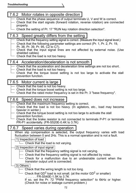
Troubleshooting
72
7.6.2 Motor rotates in opposite directionCheck that the phase sequence of output terminals U, V and W is correct.Check that the start signals (forward rotation, reverse rotation) are connectedproperly.Check the setting of Pr. 17 "RUN key rotation direction selection".
7.6.3 Speed greatly differs from the settingCheck that the frequency setting signal is correct. (Measure the input signal level.)Check that the following parameter settings are correct (Pr. 1, Pr. 2, Pr. 19, Pr. 38, Pr. 39, Pr. 95, C2 to C7).Check that the input signal lines are not affected by external noise. (Useshielded cables)Check that the load is not too heavy.
7.6.4 Acceleration/deceleration is not smoothCheck that the acceleration and deceleration time settings are not too short.Check that the load is not too heavy.Check that the torque boost setting is not too large to activate the stallprevention function.
7.6.5 Motor current is largeCheck that the load is not too heavy.Check that the torque boost setting is not too large.Check that the rated motor frequency is set in the Pr. 3 "base frequency".
7.6.6 Speed does not increaseCheck that the maximum frequency setting is correct.Check that the load is not too heavy. (In agitators, etc., load may becomeheavier in winter.)Check that the torque boost setting is not too large to activate the stall prevention function.Check that the brake resistor is not connected to terminals P-P1 or terminalsPR-P1 accidentally. (FR-S520E-0.4K to 3.7K)
7.6.7 Speed varies during operation
1) Inspection of loadCheck that the load is not varying.
2) Inspection of input signalCheck that the frequency setting signal is not varying.Check that the frequency setting signal is not affected by noise.Check for a malfunction due to an undesirable current when thetransistor output unit is connected.
3) OthersCheck that the wiring length is not too long.Check that GD2 load is not small. (at the motor GD2 or smaller) . . . . . . FR-S540E-1.5K to 3.7KIf so, set the Pr. 72 "PWM frequency selection" to 6kHz or higher.(Check for noise or leakage current problem.)
When slip compensation is selected, the output frequency varies with loadfluctuation between 0 and 2Hz. This is a normal operation and is not a fault.
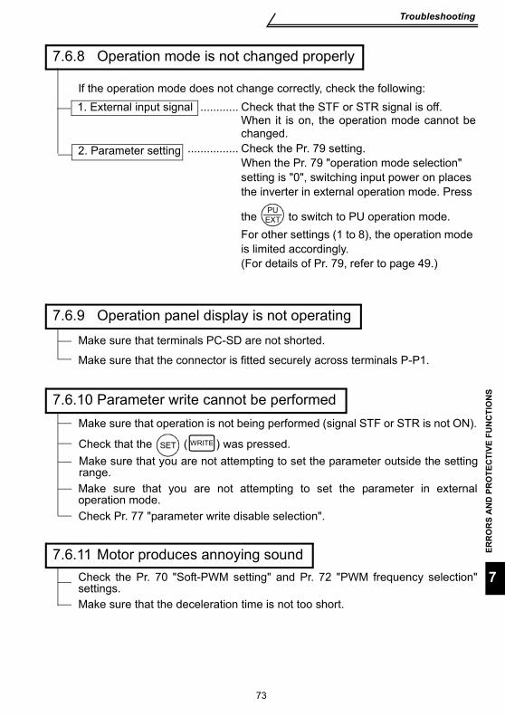
73
Troubleshooting
ERR
OR
S A
ND
PR
OTE
CTI
VE F
UN
CTI
ON
S
7
................ Check the Pr. 79 setting.When the Pr. 79 "operation mode selection" setting is "0", switching input power on places the inverter in external operation mode. Press
the to switch to PU operation mode.For other settings (1 to 8), the operation mode is limited accordingly.(For details of Pr. 79, refer to page 49.)
PUEXT
2. Parameter setting
7.6.8 Operation mode is not changed properly
If the operation mode does not change correctly, check the following:............ Check that the STF or STR signal is off.
When it is on, the operation mode cannot bechanged.
1. External input signal
7.6.9 Operation panel display is not operatingMake sure that terminals PC-SD are not shorted.
Make sure that the connector is fitted securely across terminals P-P1.
Check that the ( ) was pressed.SET WRITE
7.6.10 Parameter write cannot be performedMake sure that operation is not being performed (signal STF or STR is not ON).
Make sure that you are not attempting to set the parameter outside the settingrange.Make sure that you are not attempting to set the parameter in externaloperation mode.Check Pr. 77 "parameter write disable selection".
7.6.11 Motor produces annoying soundCheck the Pr. 70 "Soft-PWM setting" and Pr. 72 "PWM frequency selection"settings.Make sure that the deceleration time is not too short.
74
Precautions for maintenance and inspection
7.7 Precautions for maintenance and inspectionThe inverter is a static unit mainly consisting of semiconductor devices. Dailyinspection must be performed to prevent any fault from occurring due to the adverseeffects of the operating environment, such as temperature, humidity, dust, dirt andvibration, changes in the parts with time, service life, and other factors.
7.7.1 Precautions for maintenance and inspectionFor some short time after the power is switched off, a high voltage remains in thesmoothing capacitor. When accessing the inverter for inspection, wait for at least 10minutes after the power supply has been switched off, and then make sure that thevoltage across the main circuit terminals P-N of the inverter is not more than 30VDCusing a tester, etc.
7.7.2 Inspection item(1) Daily inspection
•Basically, check for the following faults during operation.1)Motor operation fault2)Improper installation environment3)Cooling system fault4)Abnormal vibration, abnormal noise5)Abnormal overheat, discoloration
• During operation, check the inverter input voltages using a tester.(2) CleaningAlways run the inverter in a clean status.When cleaning the inverter, gently wipe dirty areas with a soft cloth immersed inneutral detergent or ethanol.
7.7.3 Periodic inspectionCheck the areas inaccessible during operation and requiring periodic inspection.Consult us for periodic inspection.1)Cooling system fault. ........................... Clean the air filter, etc.2)Tightening check and retightening........ The screws and bolts may become loose
due to vibration, temperature changes, etc.Check and tighten them.Tighten them according to the specifiedtightening torque.
3)Check the conductors and insulating materials for corrosion and damage.4)Measure insulation resistance.5)Check and replace the cooling fan, smoothing capacitor and relay.
CAUTIONDo not use solvent, such as acetone, benzene, toluene and alcohol, as they willcause the inverter surface paint to peel off.
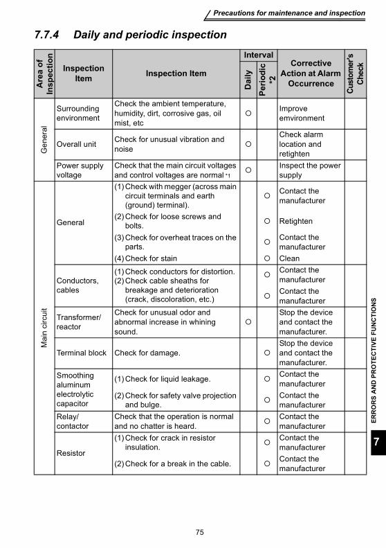
Precautions for maintenance and inspection
ERR
OR
S A
ND
PR
OTE
CTI
VE F
UN
CTI
ON
S
75
7
7.7.4 Daily and periodic inspectionA
rea
of
Insp
ectio
n
Inspection Item Inspection Item
IntervalCorrective
Action at Alarm Occurrence
Cust
omer
's Ch
eck
Dai
ly
Perio
dic
*2
Gen
eral
Surrounding environment
Check the ambient temperature, humidity, dirt, corrosive gas, oil mist, etc
Improve emvironment
Overall unit Check for unusual vibration and noise
Check alarm location and retighten
Power supply voltage
Check that the main circuit voltages and control voltages are normal *1
Inspect the power supply
Mai
n ci
rcui
t
General
(1) Check with megger (across main circuit terminals and earth (ground) terminal).
Contact the manufacturer
(2) Check for loose screws and bolts. Retighten
(3) Check for overheat traces on the parts.
Contact the manufacturer
(4) Check for stain Clean
Conductors, cables
(1) Check conductors for distortion.(2) Check cable sheaths for
breakage and deterioration (crack, discoloration, etc.)
Contact the manufacturerContact the manufacturer
Transformer/reactor
Check for unusual odor and abnormal increase in whining sound.
Stop the device and contact the manufacturer.
Terminal block Check for damage.Stop the device and contact the manufacturer.
Smoothing aluminum electrolytic capacitor
(1) Check for liquid leakage. Contact the manufacturer
(2) Check for safety valve projection and bulge.
Contact the manufacturer
Relay/contactor
Check that the operation is normal and no chatter is heard.
Contact the manufacturer
Resistor
(1) Check for crack in resistor insulation.
Contact the manufacturer
(2) Check for a break in the cable. Contact the manufacturer

Precautions for maintenance and inspection
76
*1 It is recommended to install a device to monitor voltage for checking the power supplyvoltage to the inverter.
*2 One to two years of periodic inspection cycle is recommended. However, it differs accordingto the installation environment.Consult us for periodic inspection.
Con
trol c
ircui
t / p
rote
ctiv
e ci
rcui
t
Operation check
(1) Check that the output voltages across phases with the inverter operated alone is balanced
Contact the manufacturer
(2) Check that no fault is found in protective and display circuits in a sequence protective operation test.
Contact the manufacturer
Par
ts c
heck Overall
(1) Check for unusual odor and discoloration.
Stop the device and contact the manufacturer.
(2) Check for serious rust development
Contact the manufacturer
Aluminum electrolytic capacitor
Check for liquid leakage in a capacitor and deformation trance
Contact the manufacturer
Coo
ling
syst
em Cooling fan
(1) Check for unusual vibration and noise. Replace the fan
(2) Check for loose screws and bolts Retighten
(3) Check for stain Clean
Heatsink(1) Check for clogging Clean(2) Check for stain Clean
Air filter, etc.(1) Check for clogging Clean or replace(2) Check for stain Clean or replace
Dis
play
Indication(1) Check that display is normal. Contact the
manufacturer(2) Check for stain Clean
Meter Check that reading is normalStop the device and contact the manufacturer.
Load
mot
or
Operation check
Check for vibration and abnormal increase in operation noise
Stop the device and contact the manufacturer.
Are
a of
In
spec
tion
Inspection Item Inspection Item
IntervalCorrective
Action at Alarm Occurrence
Cust
omer
's
Chec
k
Dai
ly
Perio
dic
*2
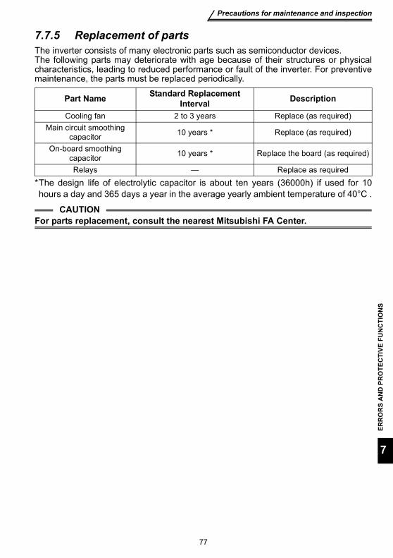
Precautions for maintenance and inspection
ERR
OR
S A
ND
PR
OTE
CTI
VE F
UN
CTI
ON
S
77
7
7.7.5 Replacement of partsThe inverter consists of many electronic parts such as semiconductor devices.The following parts may deteriorate with age because of their structures or physicalcharacteristics, leading to reduced performance or fault of the inverter. For preventivemaintenance, the parts must be replaced periodically.
*The design life of electrolytic capacitor is about ten years (36000h) if used for 10hours a day and 365 days a year in the average yearly ambient temperature of 40°C .
Part Name Standard Replacement Interval Description
Cooling fan 2 to 3 years Replace (as required)Main circuit smoothing
capacitor 10 years * Replace (as required)
On-board smoothing capacitor 10 years * Replace the board (as required)
Relays — Replace as required
CAUTIONFor parts replacement, consult the nearest Mitsubishi FA Center.
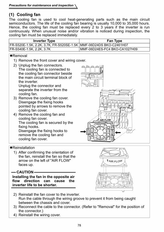
Precautions for maintenance and inspection
78
(1) Cooling fanThe cooling fan is used to cool heat-generating parts such as the main circuitsemiconductors. The life of the cooling fan bearing is usually 10,000 to 35,000 hours.Hence, the cooling fan must be replaced every 2 to 3 years if the inverter is runcontinuously. When unusual noise and/or vibration is noticed during inspection, thecooling fan must be replaced immediately.
Inverter Type Fan TypeFR-S520E-1.5K, 2.2K, 3.7K, FR-S520SE-1.5K MMF-06D24DS BKO-C2461H07FR-S540E-1.5K, 2.2K, 3.7K MMF-06D24ES-FC4 BKO-CA1027H09
Removal1) Remove the front cover and wiring cover. 2) Unplug the fan connectors.
The cooling fan is connected to the cooling fan connector beside the main circuit terminal block of the inverter.Unplug the connector and separate the inverter from the cooling fan.
3) Remove the cooling fan cover.Disengage the fixing hooks pointed by arrows to remove the cooling fan cover.
4) Remove the cooling fan and cooling fan cover.The cooling fan is secured by the fixing hooks.Disengage the fixing hooks to remove the cooling fan and cooling fan cover.
Reinstallation1) After confirming the orientation of
the fan, reinstall the fan so that the arrow on the left of "AIR FLOW" faces up.
2) Reinstall the fan cover to the inverter.Run the cable through the wiring groove to prevent it from being caught between the chassis and cover.
3) Reconnect the cable to the connector. (Refer to "Removal" for the position of the connector.)
4) Reinstall the wiring cover.
AIR FLOW
CAUTIONInstalling the fan in the opposite airflow direction can cause theinverter life to be shorter.
Precautions for maintenance and inspection
ERR
OR
S A
ND
PR
OTE
CTI
VE F
UN
CTI
ON
S
79
7
(2) Smoothing capacitorsA large-capacity aluminum electrolytic capacitor is used for smoothing in the maincircuit DC section, and an aluminum electrolytic capacitor is used for stabilizing thecontrol power in the control circuit. Their characteristics are deteriorated by theadverse effects of ripple currents, etc. The replacement intervals greatly vary with theambient temperature and operating conditions. When the inverter is operated in air-conditioned, normal environment conditions, replace the capacitors about every 10years.When a certain period of time has elapsed, the capacitors will deteriorate more rapidly.Check the capacitors at least every year (less than six months if the life will be expiredsoon).The appearance criteria for inspection are as follows:1) Case: Check the side and bottom faces for expansion2) Sealing plate: Check for remarkable warp and extreme crack.3) Check for external crack, discoloration, fluid leakage, etc. Judge that the capacitor
has reached its life when the measured capacitance of the capacitor reduced below85% of the rating.
(3) RelaysTo prevent a contact fault, etc., relays must be replaced according to the cumulativenumber of switching times (switching life).
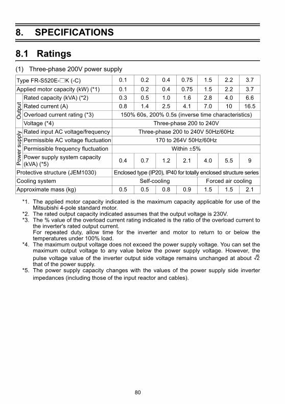
Ratings
80
8. SPECIFICATIONS
8.1 Ratings(1) Three-phase 200V power supply
*1. The applied motor capacity indicated is the maximum capacity applicable for use of theMitsubishi 4-pole standard motor.
*2. The rated output capacity indicated assumes that the output voltage is 230V.*3. The % value of the overload current rating indicated is the ratio of the overload current to
the inverter's rated output current.For repeated duty, allow time for the inverter and motor to return to or below thetemperatures under 100% load.
*4. The maximum output voltage does not exceed the power supply voltage. You can set themaximum output voltage to any value below the power supply voltage. However, thepulse voltage value of the inverter output side voltage remains unchanged at about that of the power supply.
*5. The power supply capacity changes with the values of the power supply side inverterimpedances (including those of the input reactor and cables).
Type FR-S520E- K (-C) 0.1 0.2 0.4 0.75 1.5 2.2 3.7Applied motor capacity (kW) (*1) 0.1 0.2 0.4 0.75 1.5 2.2 3.7
Out
put
Rated capacity (kVA) (*2) 0.3 0.5 1.0 1.6 2.8 4.0 6.6Rated current (A) 0.8 1.4 2.5 4.1 7.0 10 16.5Overload current rating (*3) 150% 60s, 200% 0.5s (inverse time characteristics)Voltage (*4) Three-phase 200 to 240V
Pow
er s
uppl
y Rated input AC voltage/frequency Three-phase 200 to 240V 50Hz/60HzPermissible AC voltage fluctuation 170 to 264V 50Hz/60HzPermissible frequency fluctuation Within ±5%Power supply system capacity (kVA) (*5) 0.4 0.7 1.2 2.1 4.0 5.5 9
Protective structure (JEM1030) Enclosed type (IP20), IP40 for totally enclosed structure seriesCooling system Self-cooling Forced air coolingApproximate mass (kg) 0.5 0.5 0.8 0.9 1.5 1.5 2.1
2
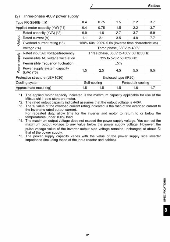
Ratings
SPEC
IFIC
ATI
ON
S
81
8
(2) Three-phase 400V power supply
*1. The applied motor capacity indicated is the maximum capacity applicable for use of theMitsubishi 4-pole standard motor.
*2. The rated output capacity indicated assumes that the output voltage is 440V.*3. The % value of the overload current rating indicated is the ratio of the overload current to
the inverter's rated output current.For repeated duty, allow time for the inverter and motor to return to or below thetemperatures under 100% load.
*4. The maximum output voltage does not exceed the power supply voltage. You can set themaximum output voltage to any value below the power supply voltage. However, thepulse voltage value of the inverter output side voltage remains unchanged at about that of the power supply.
*5. The power supply capacity varies with the value of the power supply side inverterimpedance (including those of the input reactor and cables).
Type FR-S540E- K 0.4 0.75 1.5 2.2 3.7Applied motor capacity (kW) (*1) 0.4 0.75 1.5 2.2 3.7
Out
put
Rated capacity (kVA) (*2) 0.9 1.6 2.7 3.7 5.9Rated current (A) 1.1 2.1 3.5 4.8 7.7Overload current rating (*3) 150% 60s, 200% 0.5s (Inverse time characteristics)Voltage (*4) Three phase, 380V to 480V
Pow
er s
uppl
y Rated input AC voltage/frequency Three phase, 380V to 480V 50Hz/60HzPermissible AC voltage fluctuation 325 to 528V 50Hz/60HzPermissible frequency fluctuation ±5%Power supply system capacity (kVA) (*5) 1.5 2.5 4.5 5.5 9.5
Protective structure (JEM1030) Enclosed type (IP20)Cooling system Self-cooling Forced air coolingApproximate mass (kg) 1.5 1.5 1.5 1.6 1.7
2
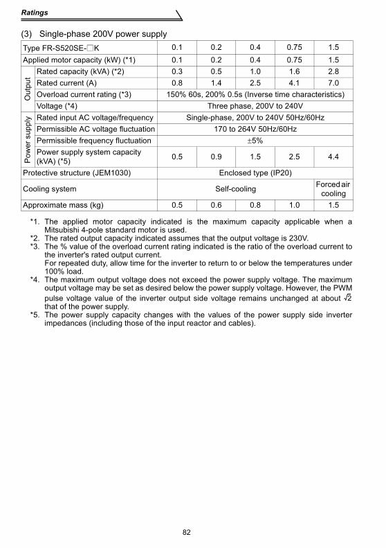
Ratings
82
(3) Single-phase 200V power supply
*1. The applied motor capacity indicated is the maximum capacity applicable when aMitsubishi 4-pole standard motor is used.
*2. The rated output capacity indicated assumes that the output voltage is 230V.*3. The % value of the overload current rating indicated is the ratio of the overload current to
the inverter's rated output current.For repeated duty, allow time for the inverter to return to or below the temperatures under100% load.
*4. The maximum output voltage does not exceed the power supply voltage. The maximumoutput voltage may be set as desired below the power supply voltage. However, the PWMpulse voltage value of the inverter output side voltage remains unchanged at about that of the power supply.
*5. The power supply capacity changes with the values of the power supply side inverterimpedances (including those of the input reactor and cables).
Type FR-S520SE- K 0.1 0.2 0.4 0.75 1.5Applied motor capacity (kW) (*1) 0.1 0.2 0.4 0.75 1.5
Out
put
Rated capacity (kVA) (*2) 0.3 0.5 1.0 1.6 2.8Rated current (A) 0.8 1.4 2.5 4.1 7.0Overload current rating (*3) 150% 60s, 200% 0.5s (Inverse time characteristics)Voltage (*4) Three phase, 200V to 240V
Pow
er s
uppl
y Rated input AC voltage/frequency Single-phase, 200V to 240V 50Hz/60HzPermissible AC voltage fluctuation 170 to 264V 50Hz/60HzPermissible frequency fluctuation ±5%Power supply system capacity (kVA) (*5) 0.5 0.9 1.5 2.5 4.4
Protective structure (JEM1030) Enclosed type (IP20)
Cooling system Self-cooling Forced air cooling
Approximate mass (kg) 0.5 0.6 0.8 1.0 1.5
2

Ratings
SPEC
IFIC
ATI
ON
S
83
8
(4) Single-phase 100V power supply
*1. The applied motor capacity indicated is the maximum capacity applicable when aMitsubishi 4-pole standard motor is used.
*2. The rated output capacity indicated assumes that the output voltage is 230V.*3. The % value of the overload current rating indicated is the ratio of the overload current to
the inverter's rated output current.For repeated duty, allow time for the inverter to return to or below the temperatures under100% load.
*4. For single-phase 100V power input, the output voltage provided cannot be twice or morethan the power supply voltage.
*5. The power supply capacity changes with the values of the power supply side inverterimpedances (including those of the input reactor and cables).
*6. For single-phase 100V power input, the application of motor load reduces the outputvoltage about 10 to 15%. Therefore, the load must be reduced when a general-purposemotor is used.
Type FR-S510WE- K 0.1 0.2 0.4 0.75Applied motor capacity (kW) (*1) 0.1 0.2 0.4 0.75
Out
put
Rated capacity (kVA) (*2) 0.3 0.5 1.0 1.6Rated current (A) 0.8 1.4 2.5 4.1Overload current rating (*3) 150% 60s, 200% 0.5s (Inverse time characteristics)Voltage Three phase, 200V to 230V (*4, 6)
Pow
er s
uppl
y Rated input AC voltage/frequency Single-phase, 100V to 115V 50Hz/60HzPermissible AC voltage fluctuation 90 to 132V 50Hz/60HzPermissible frequency fluctuation ±5%Power supply system capacity (kVA) (*5) 0.5 0.9 1.5 2.5
Protective structure (JEM1030) Enclosed type (IP20)Cooling system Self-coolingApproximate mass (kg) 0.6 0.7 0.9 1.6
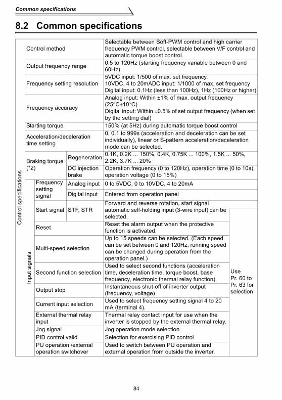
Common specifications
84
8.2 Common specificationsC
ontro
l spe
cific
atio
ns
Control methodSelectable between Soft-PWM control and high carrier frequency PWM control, selectable between V/F control and automatic torque boost control.
Output frequency range 0.5 to 120Hz (starting frequency variable between 0 and 60Hz)
Frequency setting resolution5VDC input: 1/500 of max. set frequency, 10VDC, 4 to 20mADC input: 1/1000 of max. set frequencyDigital input: 0.1Hz (less than 100Hz), 1Hz (100Hz or higher)
Frequency accuracy
Analog input: Within ±1% of max. output frequency (25°C±10°C)Digital input: Within ±0.5% of set output frequency (when set by the setting dial)
Starting torque 150% (at 5Hz) during automatic torque boost control
Acceleration/decelerationtime setting
0, 0.1 to 999s (acceleration and deceleration can be set individually), linear or S-pattern acceleration/deceleration mode can be selected.
Braking torque (*2)
Regeneration 0.1K, 0.2K ... 150%, 0.4K, 0.75K ... 100%, 1.5K ... 50%, 2.2K, 3.7K ... 20%
DC injection brake
Operation frequency (0 to 120Hz), operation time (0 to 10s), operation voltage (0 to 15%)
Inpu
t sig
nals
Frequency setting signal
Analog input 0 to 5VDC, 0 to 10VDC, 4 to 20mA
Digital input Entered from operation panel
Start signal STF, STRForward and reverse rotation, start signal automatic self-holding input (3-wire input) can be selected.
Use Pr. 60 to Pr. 63 for selection
Reset Reset the alarm output when the protective function is activated.
Multi-speed selection
Up to 15 speeds can be selected. (Each speed can be set between 0 and 120Hz, running speed can be changed during operation from the operation panel.)
Second function selectionUsed to select second functions (acceleration time, deceleration time, torque boost, base frequency, electronic thermal relay function).
Output stop Instantaneous shut-off of inverter output (frequency, voltage)
Current input selection Used to select frequency setting signal 4 to 20 mA (terminal 4).
External thermal relay input
Thermal relay contact input for use when the inverter is stopped by the external thermal relay.
Jog signal Jog operation mode selectionPID control valid Selection for exercising PID controlPU operation /external operation switchover
Used to switch between PU operation and external operation from outside the inverter.
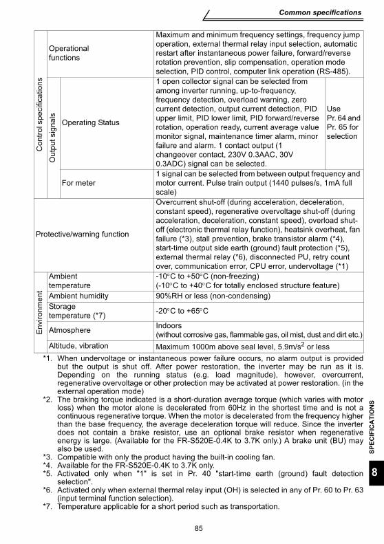
Common specifications
SPEC
IFIC
ATI
ON
S
85
8
*1. When undervoltage or instantaneous power failure occurs, no alarm output is providedbut the output is shut off. After power restoration, the inverter may be run as it is.Depending on the running status (e.g. load magnitude), however, overcurrent,regenerative overvoltage or other protection may be activated at power restoration. (in theexternal operation mode)
*2. The braking torque indicated is a short-duration average torque (which varies with motorloss) when the motor alone is decelerated from 60Hz in the shortest time and is not acontinuous regenerative torque. When the motor is decelerated from the frequency higherthan the base frequency, the average deceleration torque will reduce. Since the inverterdoes not contain a brake resistor, use an optional brake resistor when regenerativeenergy is large. (Available for the FR-S520E-0.4K to 3.7K only.) A brake unit (BU) mayalso be used.
*3. Compatible with only the product having the built-in cooling fan.*4. Available for the FR-S520E-0.4K to 3.7K only.*5. Activated only when "1" is set in Pr. 40 "start-time earth (ground) fault detection
selection".*6. Activated only when external thermal relay input (OH) is selected in any of Pr. 60 to Pr. 63
(input terminal function selection).*7. Temperature applicable for a short period such as transportation.
Con
trol s
peci
ficat
ions
Operational functions
Maximum and minimum frequency settings, frequency jump operation, external thermal relay input selection, automatic restart after instantaneous power failure, forward/reverse rotation prevention, slip compensation, operation mode selection, PID control, computer link operation (RS-485).
Out
put s
igna
ls
Operating Status
1 open collector signal can be selected from among inverter running, up-to-frequency, frequency detection, overload warning, zero current detection, output current detection, PID upper limit, PID lower limit, PID forward/reverse rotation, operation ready, current average value monitor signal, maintenance timer alarm, minor failure and alarm. 1 contact output (1 changeover contact, 230V 0.3AAC, 30V 0.3ADC) signal can be selected.
Use Pr. 64 and Pr. 65 for selection
For meter1 signal can be selected from between output frequency and motor current. Pulse train output (1440 pulses/s, 1mA full scale)
Protective/warning function
Overcurrent shut-off (during acceleration, deceleration, constant speed), regenerative overvoltage shut-off (during acceleration, deceleration, constant speed), overload shut-off (electronic thermal relay function), heatsink overheat, fan failure (*3), stall prevention, brake transistor alarm (*4), start-time output side earth (ground) fault protection (*5), external thermal relay (*6), disconnected PU, retry count over, communication error, CPU error, undervoltage (*1)
Env
ironm
ent
Ambient temperature
-10°C to +50°C (non-freezing)(-10°C to +40°C for totally enclosed structure feature)
Ambient humidity 90%RH or less (non-condensing)Storage temperature (*7) -20°C to +65°C
Atmosphere Indoors (without corrosive gas, flammable gas, oil mist, dust and dirt etc.)
Altitude, vibration Maximum 1000m above seal level, 5.9m/s2 or less

OUTLINE DIMENSION DRAWINGS
86
9. OUTLINE DIMENSION DRAWINGS
•FR-S520E-0.1K, 0.2K, 0.4K, 0.75K•FR-S520SE-0.1K, 0.2K, 0.4K, 0.75K•FR-S510WE-0.1K, 0.2K, 0.4K
•Three-phase 200V power supply
•Single-phase 200V power supply
•Single-phase 100V power supply
(Unit: mm)
Capacity D D1 D20.1K,0.2K 80.5 10 52
0.4K 112.5 42 520.75K 132.5 62 52
Capacity D D1 D20.1K,0.2K 80.5 10 52
0.4K 142.5 42 820.75K 162.5 62 82
Capacity D D1 D20.1K 80.5 10 520.2K 110.5 10 820.4K 142.5 42 82
REMARKSFor dimensions of the totally enclosed structure type, refer to those of the standard typeinverter of the same capacity.
φ5 hole
- +
D1D2D
Rating plate
686 56 6
5
128
511
85
18.54
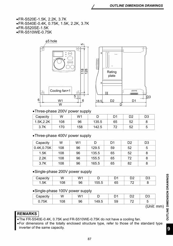
OUTLINE DIMENSION DRAWINGS
OU
TLIN
E D
IMEN
SIO
N D
RA
WIN
GS
87
9
•FR-S520E-1.5K, 2.2K, 3.7K•FR-S540E-0.4K, 0.75K, 1.5K, 2.2K, 3.7K•FR-S520SE-1.5K•FR-S510WE-0.75K
•Three-phase 200V power supply
•Three-phase 400V power supply
•Single-phase 200V power supply
•Single-phase 100V power supply
(Unit: mm)
Capacity W W1 D D1 D2 D31.5K,2.2K 108 96 135.5 65 52 8
3.7K 170 158 142.5 72 52 5
Capacity W W1 D D1 D2 D30.4K,0.75K 108 96 129.5 59 52 5
1.5K 108 96 135.5 65 52 82.2K 108 96 155.5 65 72 83.7K 108 96 165.5 65 82 8
Capacity W W1 D D1 D2 D31.5K 108 96 155.5 65 72 8
Capacity W W1 D D1 D2 D30.75K 108 96 149.5 59 72 5
REMARKS•The FR-S540E-0.4K, 0.75K and FR-S510WE-0.75K do not have a cooling fan.•For dimensions of the totally enclosed structure type, refer to those of the standard typeinverter of the same capacity.
DD2 D1
D3
WW1
- +
Cooling fan×1
Rating plate
φ5 hole
18.5
118
5
128
5
6 6
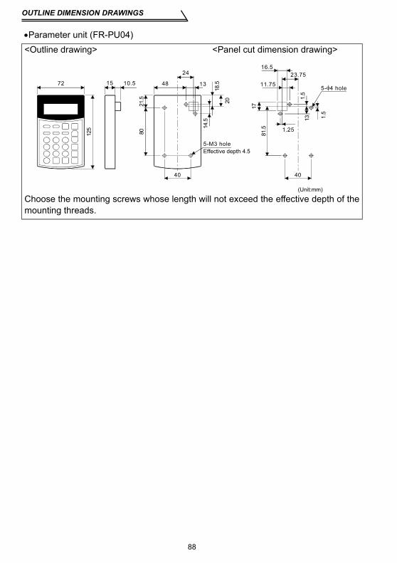
OUTLINE DIMENSION DRAWINGS
88
•Parameter unit (FR-PU04)<Outline drawing> <Panel cut dimension drawing>
Choose the mounting screws whose length will not exceed the effective depth of themounting threads.
5-M3 hole
5- 4 hole
Effective depth 4.5
40
23.75
11.75
81.5 1.25
1.5
17
16.5
1.5
72 15 10.5
18.5
80
48
24
13
2021.5
14.5
13
40
(Unit:mm)
125
89
(The products conforming to the Low Voltage Directive carry the CE mark.)
(1) EMC Directive1)Our view of transistorized inverters for the EMC Directive
A transistorized inverter is a component designed for installation in an enclosure andfor use with the other equipment to control the equipment/device. Therefore, weunderstand that the EMC Directive does not apply directly to transistorized inverters.For this reason, we do not place the CE mark on the transistorized inverters. (TheCE mark is placed on inverters in accordance with the Low Voltage Directive.) TheEuropean power drive manufacturers' organization (CEMEP) also holds this point ofview.
2)ComplianceWe understand that the transistorized inverters are not covered directly by the EMCDirective. However, the EMC Directive applies to machines/equipment into whichtransistorized inverters have been incorporated, and these machines andequipment must carry the CE marks. Hence, we prepared the European Standard-compliant noise filters and the technical information "EMC Installation Guidelines"(information number BCN-A21041-202) so that machines and equipmentincorporating transistorized inverters may conform to the EMC Directive moreeasily.
3)Outline of installation methodInstall an inverter using the following methods:* Use the inverter with an European Standard-compliant noise filter.* For wiring between the inverter and motor, use shielded cables or run them in a
metal piping and earth (ground) the cables on the inverter and motor sides with theshortest possible distance.
* Insert a common mode filter and ferrite core into the power and control lines asrequired.
Full information including the European Standard-compliant noise filterspecifications are written in the technical information "EMC Installation Guidelines"(BCN-A21041-202). Please contact your sales representative.
Appendix 1 Instructions for compliance with the European Directive

90
(2) Low Voltage Directive1)Our view of transistorized inverters for the Low Voltage Directive
Transistorized inverters are covered by the Low Voltage Directive (Standard toconform to: EN50178).
2)ComplianceWe have self-confirmed our inverters as products compliant to the Low VoltageDirective and place the CE mark on the inverters.
3)Outline of instructions* For the 400V class inverter, the rated input voltage range is three-phase 380V to
415V 50Hz/60Hz.* Do not use an earth leakage circuit breaker as an electric shock protector without
connecting the equipment to the earth. Connect the equipment to the earth securely.* Wire the earth terminal independently. (Do not connect two or more cables to one
terminal.)* Use the cable sizes on page 11 under the following conditions.
·Ambient temperature: 40°C maximum·Wire installation: On wall without ducts or conduitsIf conditions are different from above, select appropriate wire according toEN60204 ANNEX C TABLE 5.
* Use the moulded case circuit breaker and magnetic contactor which conform tothe EN or IEC Standard.
* Use the breaker of type B (breaker which can detect both AC and DC). If not,provide double or enhanced insulation between the inverter and other equipment,or put a transformer between the main power supply and inverter.
* Use the inverter under the conditions of overvoltage category II and contaminationlevel 2 or higher specified in IEC664.
* On the input and output of the inverter, use cables of the type and size set forth inEN60204 Appendix C.
* The operating capacity of the relay outputs (terminal symbols A, B, C) should be30VDC, 0.3A.
* Control circuit terminals on page 7 are safely isolated from the main circuit.* Environment
Details are given in the technical information "Low Voltage Directive ConformanceGuide" (BCN-A21041-203). Please contact your sales representative.
During operation In storage During transportation
Ambient Temperature -10°C to +50°C -20°C to +65°C -20°C to +65°CAmbient Humidity 90% RH or less 90% RH or less 90% RH or lessMaximum Altitude 1,000m 1,000m 10,000m

91
(Standard to comply with: UL 508C, CSA C22.2 No.14)
1. InstallationThe S500E is UL-listed as a product for use in an enclosure.Design the enclosure so that the ambient temperature, humidity and ambience ofthe inverter will satisfy the above specifications. (Refer to page 85)Branch circuit protectionFor installation in the United States, branch circuit protection must be provided inaccordance with the National Electrical Code and any applicable local codes.For installation in Canada, branch circuit protection must be provided in accordancewith the Canada Electrical Code and any applicable provincial codes.
2. Wiring of the power supply and motorFor wiring the input (R, S, T) and output (U, V, W) terminals of the inverter, use theUL-listed copper wires (rated at 75°C) and round crimping terminals. Crimp thecrimping terminals with the crimping tool recommended by the terminal maker.
3. Short circuit ratingsSuitable For Use in A Circuit Capable Of Delivering Not More Than 100kA rmsSymmetrical Amperes.
Appendix 2 Instructions for UL and cUL
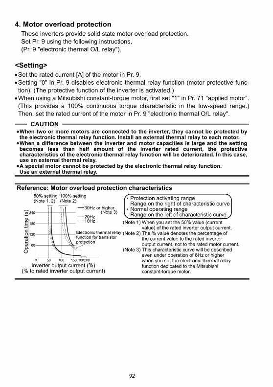
92
4. Motor overload protectionThese inverters provide solid state motor overload protection.Set Pr. 9 using the following instructions,(Pr. 9 "electronic thermal O/L relay").
<Setting>•Set the rated current [A] of the motor in Pr. 9.•Setting "0" in Pr. 9 disables electronic thermal relay function (motor protective func-tion). (The protective function of the inverter is activated.)•When using a Mitsubishi constant-torque motor, first set "1" in Pr. 71 "applied motor".(This provides a 100% continuous torque characteristic in the low-speed range.)Then, set the rated current of the motor in Pr. 9 "electronic thermal O/L relay".
CAUTION•When two or more motors are connected to the inverter, they cannot be protected bythe electronic thermal relay function. Install an external thermal relay to each motor.•When a difference between the inverter and motor capacities is large and the settingbecomes less than half amount of the inverter rated current, the protectivecharacteristics of the electronic thermal relay function will be deteriorated. In this case,use an external thermal relay.•A special motor cannot be protected by the electronic thermal relay function.Use an external thermal relay.
Reference: Motor overload protection characteristics
0 50 100 150 180200
240
180
120
60
Ope
ratio
n tim
e (s
)
50% setting(Note 1, 2)
100% setting(Note 2)
(Note 1) When you set the 50% value (current value) of the rated inverter output current.(Note 2) The % value denotes the percentage of the current value to the rated inverter output current, not to the rated motor current.(Note 3) This characteristic curve will be described even under operation of 6Hz or higher when you set the electronic thermal relay function dedicated to the Mitsubishi constant-torque motor.
30Hz or higher (Note 3)
Inverter output current (%)(% to rated inverter output current)
Electronic thermal relayfunction for transistorprotection
20Hz10Hz
Protection activating range Range on the right of characteristic curveNormal operating rangeRange on the left of characteristic curve

93
MEMO
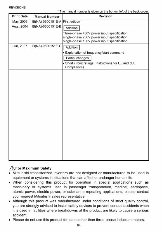
94
REVISIONS* The manual number is given on the bottom left of the back cover.
For Maximum Safety• Mitsubishi transistorized inverters are not designed or manufactured to be used in
equipment or systems in situations that can affect or endanger human life.• When considering this product for operation in special applications such as
machinery or systems used in passenger transportation, medical, aerospace,atomic power, electric power, or submarine repeating applications, please contactyour nearest Mitsubishi sales representative.
• Although this product was manufactured under conditions of strict quality control,you are strongly advised to install safety devices to prevent serious accidents whenit is used in facilities where breakdowns of the product are likely to cause a seriousaccident.
• Please do not use this product for loads other than three-phase induction motors.
Print Date *Manual Number RevisionMay, 2003 IB(NA)-0600151E-A First editionAug., 2004 IB(NA)-0600151E-B
Three-phase 400V power input specification, single-phase 200V power input specification, single-phase 100V power input specification
Jun, 2007 IB(NA)-0600151E-C
• Explanation of frequency/start command
• Short circuit ratings (Instructions for UL and cUL Compliance)
Addition
Addition
Partial changes