Embed Size (px)
Citation preview
FR-D700-GINSTRUCTION MANUAL (BASIC)FR-D720-0.2K to 3.7K-G
S-PM GEARED MOTOR DRIVE UNIT
7004
5
6
7
8
9
3
2
1
CONTENTS
OUTLINE ...................................................................................1
INSTALLATION AND WIRING ...................................................5
PRECAUTIONS FOR USE OF THE DRIVE UNIT ......................16
FAILSAFE OF THE SYSTEM WHICH USES THE DRIVE UNIT.18
DRIVE THE MOTOR.................................................................19
PARAMETERS .........................................................................27
TROUBLESHOOTING ..............................................................31
PRECAUTIONS FOR MAINTENANCE AND INSPECTION........36
SPECIFICATIONS....................................................................38
Thank you for choosing this Mitsubishi Electric S-PM geared motor drive unit.This Instruction Manual (Basic) provides handling information and precautions for use of the equipment.Please forward this Instruction Manual (Basic) to the end user.
To obtain the Instruction Manual (Applied)Contact where you purchased the drive unit, your Mitsubishi Electricsales representative, or the nearest Mitsubishi Electric FA Center for thefollowing manuals: Instruction Manual (Applied) [IB(NA)-0600478ENG]These manuals are required if you are going to utilize functions andperformance.
The PDF version of this manual is also available for download at the"Mitsubishi Electric Factory Automation Website", which is aninformation service offered on the Internet. (URL: www.MitsubishiElectric.co.jp/fa/)
1
2
3
4
5
6
7
8
9

This Instruction Manual (Basic) provides handling information and precautions for use of the equipment.Please forward this Instruction Manual (Basic) to the end user.
1. Electric Shock Prevention
2. Fire Prevention
3.Injury Prevention
4. Additional InstructionsAlso the following points must be noted to prevent an accidentalfailure, injury, electric shock, etc.(1) Transportation and Mounting
This section is specifically about safety mattersDo not attempt to install, operate, maintain or inspect the driveunit until you have read through the Instruction Manual (Basic)and appended documents carefully and can use the equipmentcorrectly. Do not use this product until you have a fullknowledge of the equipment, safety information andinstructions.In this Instruction Manual (Basic), the safety instruction levelsare classified into "WARNING" and "CAUTION".
Incorrect handling may causehazardous conditions, resulting in deathor severe injury.
Incorrect handling may causehazardous conditions, resulting inmedium or slight injury, or may causeonly material damage.
The level may even lead to a seriousconsequence according to conditions. Both instruction levelsmust be followed because these are important to personalsafety.
While power is ON or when the drive unit is running, do notopen the front cover. Otherwise you may get an electric shock.Do not run the drive unit with the front cover or wiring coverremoved. Otherwise you may access the exposed high-voltage terminals or the charging part of the circuitry andget an electric shock.Even if power is OFF, do not remove the front cover exceptfor wiring or periodic inspection. You may accidentallytouch the charged drive unit circuits and get an electricshock.Before wiring or inspection, power must be switched OFF.To confirm that, LED indication of the operation panel mustbe checked. (It must be OFF.) Any person who is involved inwiring or inspection shall wait for at least 10 minutes afterthe power supply has been switched OFF and check thatthere are no residual voltage using a tester or the like. Thecapacitor is charged with high voltage for some time afterpower OFF, and it is dangerous.This drive unit must be earthed (grounded). Earthing(grounding) must conform to the requirements of nationaland local safety regulations and electrical code (NECsection 250, IEC 536 class 1 and other applicable standards).Any person who is involved in wiring or inspection of thisequipment shall be fully competent to do the work.The drive unit must be installed before wiring. Otherwiseyou may get an electric shock or be injured.Setting dial and key operations must be performed with dryhands to prevent an electric shock. Otherwise you may getan electric shock.Do not subject the cables to scratches, excessive stress, heavyloads or pinching. Otherwise you may get an electric shock.Do not change the cooling fan while power is ON. It isdangerous to change the cooling fan while power is ON.Do not touch the printed circuit board or handle the cableswith wet hands. Otherwise you may get an electric shock.When measuring the main circuit capacitor capacity, the DCvoltage is applied to the motor for 1s at powering OFF. Nevertouch the motor terminal, etc. right after powering OFF toprevent an electric shock.A PM motor is a synchronous motor with embeddedmagnets. High-voltage is generated at motor terminals whilethe motor is running even after the drive unit power is turnedOFF. Before wiring or inspection, the motor must beconfirmed to be stopped. For applications where the motor isdriven by the load, the low-voltage manual contactor, whichis installed at the drive unit's output side, must be openedbefore wiring or inspection. Otherwise you may get anelectric shock.
WARNING
CAUTION
CAUTION
WARNING
Drive unit must be installed on a nonflammable wall withoutholes (so that nobody touches the drive unit heatsink on therear side, etc.). Mounting it to or near flammable materialcan cause a fire.If the drive unit has become faulty, the drive unit power mustbe switched OFF. A continuous flow of large current couldcause a fire.When using a brake resistor, a sequence that will turn OFFpower when a fault signal is output must be configured.Otherwise the brake resistor may overheat due to damage ofthe brake transistor and possibly cause a fire.Do not connect a resistor directly to the DC terminals P/+and N/-. Doing so could cause a fire.
The voltage applied to each terminal must be the onesspecified in the Instruction Manual. Otherwise burst,damage, etc. may occur.The cables must be connected to the correct terminals.Otherwise burst, damage, etc. may occur.Polarity must be correct. Otherwise burst, damage, etc. mayoccur.While power is ON or for some time after power-OFF, do nottouch the drive unit since the drive unit will be extremelyhot. Doing so can cause burns.
The product must be transported in correct method thatcorresponds to the weight. Failure to do so may lead toinjuries. Do not stack the boxes containing drive units higher thanthe number recommended.The product must be installed to the position wherewithstands the weight of the product according to theinformation in the Instruction Manual.Do not install or operate the drive unit if it is damaged or hasparts missing.When carrying the drive unit, do not hold it by the frontcover or setting dial; it may fall off or fail.Do not stand or rest heavy objects on the product.The drive unit mounting orientation must be correct.Foreign conductive objects must be prevented fromentering the drive unit. That includes screws and metalfragments or other flammable substance such as oil.As the drive unit is a precision instrument, do not drop orsubject it to impact.The drive unit must be used under the followingenvironment: Otherwise the drive unit may be damaged.
∗ Temperature applicable for a short time, e.g. in transit.
CAUTION
CAUTION
CAUTION
Envi
ronm
ent
Surroundingairtemperature
-10°C to +50°C (non-freezing)
Ambienthumidity 90%RH or less (non-condensing)
Storagetemperature -20°C to +65°C ∗
Atmosphere Indoors (free from corrosive gas, flammable gas,oil mist, dust and dirt)
Altitude/vibration
Maximum 1,000m above sea level.5.9m/s2 or less at 10 to 55Hz (directions of X, Y, Zaxes)
A-1

(2) Wiring
(3) Trial run
(4) Usage
(5) Emergency stop
(6) Maintenance, inspection and parts replacement
(7) Disposal
Do not install a power factor correction capacitor or surgesuppressor/capacitor type filter on the drive unit outputside. These devices on the drive unit output side may beoverheated or burn out.The connection orientation of the output cables U, V, W tothe motor affects the rotation direction of the motor.PM motor terminals (U, V, W) hold high-voltage while the PMmotor is running even after the power is turned OFF. Beforewiring, the PM motor must be confirmed to be stopped.Otherwise you may get an electric shock.Never connect a PM motor to the commercial power supply.Applying the commercial power supply to input terminals (U,V, W) of a PM motor will burn the PM motor. The PM motormust be connected with the output terminals (U, V, W) of thedrive unit.
Before starting operation, each parameter must beconfirmed and adjusted. A failure to do so may cause somemachines to make unexpected motions.
A PM motor and the drive unit must be used in the specifiedcapacity combination.Do not use multiple PM motors with one drive unit.Any person must stay away from the equipment when theretry function is set as it will restart suddenly after trip.
Since pressing key may not stop output depending on
the function setting status, separate circuit and switch thatmake an emergency stop (power OFF, mechanical brakeoperation for emergency stop, etc.) must be provided.OFF status of the start signal must be confirmed beforeresetting the drive unit fault. Resetting drive unit alarm withthe start signal ON restarts the motor suddenly.Do not use a PM motor in an application where a motor isdriven by its load and runs at a speed higher than themaximum motor speed. Do not use a synchronized, induction, or induced-synchronized motor, that is not a dedicated PM motor.Do not use the drive unit for a load other than the dedicatedPM motor.Connection of any other electrical equipment to the driveunit output may damage the equipment.Do not modify the equipment.Do not perform parts removal which is not instructed in thismanual. Doing so may lead to fault or damage of the product.
CAUTION
CAUTION
WARNING
The electronic thermal relay function does not guaranteeprotection of the motor from overheating. It is recommendedto install an external thermal for overheat protection.Do not use a magnetic contactor on the drive unit input forfrequent starting/stopping of the drive unit. Otherwise, thelife of the drive unit decreases.The effect of electromagnetic interference must be reducedby using an EMC filter or by other means. Otherwise nearbyelectronic equipment may be affected.Appropriate measures must be taken to suppressharmonics. Otherwise power supply harmonics from thedrive unit may heat/damage the power factor correctioncapacitor and generator.When parameter clear or all parameter clear is performed, therequired parameters must be set again before startingoperations because all parameters return to the initial value.The drive unit can be easily set for high-speed operation.Before changing its setting, the performances of the motorand machine must be fully examined.Stop status cannot be hold by the drive unit's brakefunction. In addition to the drive unit's brake function, aholding device must be installed to ensure safety.Before running a drive unit which had been stored for a longperiod, inspection and test operation must be performed.Static electricity in your body must be discharged beforeyou touch the product. Otherwise the product may bedamaged.In the system with a PM motor, the drive unit power must beturned ON before closing the contacts of the contactor at theoutput side.If you are installing the drive unit to drive a three-phasedevice while you are contracted for lighting and powerservice, consult your electric power supplier.
A safety backup such as an emergency brake must beprovided to prevent hazardous condition to the machine andequipment in case of drive unit failure.When the breaker on the drive unit input side trips, thewiring must be checked for fault (short circuit), and internalparts of the drive unit for a damage, etc. The cause of the tripmust be identified and removed before turning ON the powerof the breaker.When any protective function is activated, appropriatecorrective action must be taken, and the drive unit must bereset before resuming operation.
Do not carry out a megger (insulation resistance) test on thecontrol circuit of the drive unit. It will cause a failure.
The drive unit must be treated as industrial waste.
General instructionMany of the diagrams and drawings in this Instruction Manual(Basic) show the drive unit without a cover or partially openfor explanation. Never operate the drive unit in this manner.The cover must be always reinstalled and the instruction inthis Instruction Manual (Basic) must be followed whenoperating the drive unit.For more details on a dedicated PM motor, refer to theInstruction Manual of the dedicated PM motor.
CAUTION
CAUTION
CAUTION
CAUTION
A-2
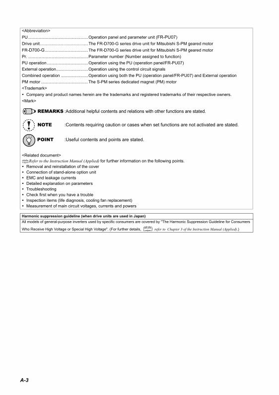
<Abbreviation>PU...................................................Operation panel and parameter unit (FR-PU07)Drive unit.........................................The FR-D700-G series drive unit for Mitsubishi S-PM geared motorFR-D700-G.....................................The FR-D700-G series drive unit for Mitsubishi S-PM geared motorPr. ...................................................Parameter number (Number assigned to function)PU operation...................................Operation using the PU (operation panel/FR-PU07)External operation...........................Operation using the control circuit signalsCombined operation .......................Operation using both the PU (operation panel/FR-PU07) and External operationPM motor ........................................The S-PM series dedicated magnet (PM) motor<Trademark>
Company and product names herein are the trademarks and registered trademarks of their respective owners.<Mark>
REMARKS :Additional helpful contents and relations with other functions are stated.
NOTE :Contents requiring caution or cases when set functions are not activated are stated.
POINT :Useful contents and points are stated.
<Related document>Refer to the Instruction Manual (Applied) for further information on the following points.
Removal and reinstallation of the coverConnection of stand-alone option unitEMC and leakage currentsDetailed explanation on parametersTroubleshootingCheck first when you have a troubleInspection items (life diagnosis, cooling fan replacement)Measurement of main circuit voltages, currents and powers
Harmonic suppression guideline (when drive units are used in Japan)All models of general-purpose inverters used by specific consumers are covered by "The Harmonic Suppression Guideline for Consumers
Who Receive High Voltage or Special High Voltage". (For further details, refer to Chapter 3 of the Instruction Manual (Applied).)
A-3
1
1
1 OUTLINE
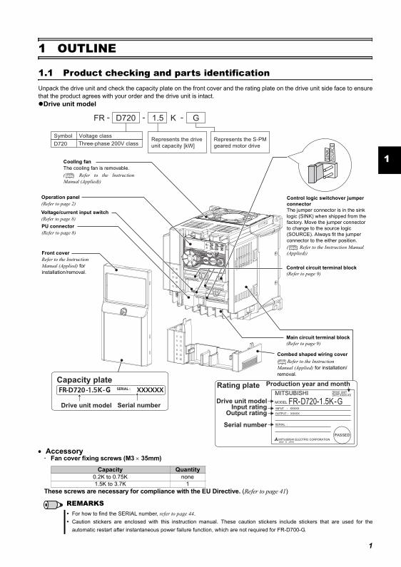
1.1 Product checking and parts identificationUnpack the drive unit and check the capacity plate on the front cover and the rating plate on the drive unit side face to ensurethat the product agrees with your order and the drive unit is intact.
Drive unit model
• Accessory· Fan cover fixing screws (M3 × 35mm)
These screws are necessary for compliance with the EU Directive. (Refer to page 41)
Capacity Quantity0.2K to 0.75K none1.5K to 3.7K 1
REMARKSFor how to find the SERIAL number, refer to page 44.Caution stickers are enclosed with this instruction manual. These caution stickers include stickers that are used for theautomatic restart after instantaneous power failure function, which are not required for FR-D700-G.
FR - -
Symbol Voltage class
D720 1.5 - G
Represents the drive
unit capacity [kW]
Represents the S-PM
geared motor drive
K
D720 Three-phase 200V class
Capacity plate
Drive unit model Serial number
Rating plate
Drive unit modelInput rating
Output rating
Serial number
D720 G
DRIVE UNITDATE:XXXX-XX
Production year and month
Control circuit terminal block(Refer to page 9)
Control logic switchover jumper connectorThe jumper connector is in the sink logic (SINK) when shipped from the factory. Move the jumper connector to change to the source logic (SOURCE). Always fit the jumper connector to the either position. ( Refer to the Instruction Manual (Applied))
Combed shaped wiring coverRefer to the Instruction
Manual (Applied) for installation/removal.
Main circuit terminal block(Refer to page 9)
Front coverRefer to the Instruction Manual (Applied) for installation/removal.
PU connector(Refer to page 8)
Voltage/current input switch(Refer to page 8)
Operation panel(Refer to page 2)
Cooling fanThe cooling fan is removable.( Refer to the InstructionManual (Applied))

Operation panel
1.2 Operation panel
1.2.1 Names and functions of the operation panelThe operation panel cannot be removed from the drive unit.
No. Component Name Description
(a) Unit indicatorHz: Lit to indicate frequency. (Flickers when the set frequency monitor is displayed.)A: Lit to indicate current.(Both "Hz" and "A" are lit to indicate a value other than frequency or current. )
(b) Monitor (4-digit LED)
Shows the speed, parameter number, etc.(To monitor the output power, the set speed and other items, set Pr. 52.)
(c) Setting dial
The dial of the Mitsubishi drive unit. The setting dial is used to change the speed and parameter settings.Press to display the following.
Displays the set speed in the monitor modePresent set value is displayed during calibrationDisplays the order in the faults history mode
(d) Start command Select the rotation direction in Pr. 40.
(e) MODE key
Used to switch among different setting modes.
Pressing simultaneously changes the operation mode.
Holding this key for 2 seconds locks the operation. The key lock is invalid when Pr. 161 = "0 (initial setting)." Refer to the Instruction Manual (Applied)
(f) SET key
Used to enter a setting.If pressed during the operation, monitored item changes as the following:
(g) Operation status indicator
Lit or flickers during drive unit operation.** Lit: When the forward rotation operation is being performed.
Slow flickering (1.4s cycle): When the reverse rotation operation is being performed.
Fast flickering (0.2s cycle): When has been pressed or the start command has been
given, but the operation cannot be made. When the speed command is less than the starting speed.When the MRS signal is being input.
(h) Parameter setting mode indicator Lit to indicate the parameter setting mode.
(i) Monitor indicator Lit to indicate the monitor mode.
(j) Operation mode indicator
PU: Lit to indicate the PU operation mode.EXT: Lit to indicate the External operation mode.(EXT is lit at power-ON in the initial setting.)NET: Lit to indicate the Network operation mode.PU and EXT: Lit to indicate EXT/PU combined operation mode 1 and 2All of these indicators are OFF when the command source is not at the operation panel.
(k) STOP/RESET key
Used to stop operation commands.Used to reset a fault when the protective function (fault) is activated.
(l) PU/EXT key
Used to switch between the PU and External operation modes.To use the External operation mode (operation using a separately connected speed setting potentiometer and start signal), press this key to light up the EXT indicator.
(Press simultaneously (0.5s), or change the Pr .79 setting to change to the combined
operation mode. ( Refer to the Instruction Manual (Applied))
PU: PU operation modeEXT: External operation modeUsed to cancel the PU stop also.
(a) Unit indicator
(b) Monitor (4-digit LED)
(c) Setting dial
(d) Start command
(e) MODE key
(f) SET key
(g) Operation status indicator
(h) Parameter setting mode indicator
(i) Monitor indicator
(j) Operation mode indicator
(k) STOP/RESET key
(l) PU/EXT key
Rotation speed → Output current → Output voltage
2
Operation panel
1
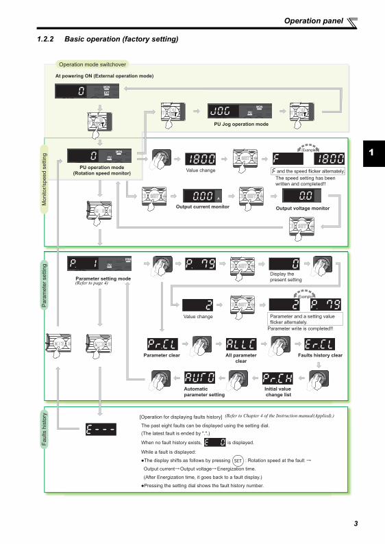
1.2.2 Basic operation (factory setting)
Automatic
parameter setting
STOP
Operation mode switchover
Para
mete
r settin
gF
aults h
isto
ryM
onitor/
speed s
ettin
g
At powering ON (External operation mode)
PU operation mode
(Rotation speed monitor)
Parameter setting mode
PU Jog operation mode
Output current monitor Output voltage monitor
Display the
present setting
Value change
Value change
Parameter write is completed!!
Parameter and a setting value
flicker alternately.
Parameter clear All parameter
clear
Faults history clear
Initial value
change list
(Example)
(Example)
The speed setting has been
written and completed!!
and the speed flicker alternately.
[Operation for displaying faults history]
The past eight faults can be displayed using the setting dial.
(The latest fault is ended by ".".)
When no fault history exists, is displayed.
While a fault is displayed:
�The display shifts as follows by pressing : Rotation speed at the fault
Output current Output voltage Energization time.
(After Energization time, it goes back to a fault display.)
�Pressing the setting dial shows the fault history number.
(Refer to Chapter 4 of the Instruction manual(Applied).)
(Refer to page 4)
3

4
Operation panel
1.2.3 Changing the parameter setting value
1.2.4 Parameter clear/all parameter clear
Changing example Change the Pr. 1 Maximum setting.
Operation
1. Screen at power-ONThe monitor display appears.
2.Changing the operation mode
Press to choose the PU operation mode. [PU] indicator is lit.
3.Parameter setting mode
Press to choose the parameter setting mode.
4.Selecting the parameter number
Turn until (Pr. 1) appears.
5.Reading the set value
Press to read the present set value.
" "(3000r/min (initial value)) appears.
6.Changing the setting value
Turn to change the set value to " "(1800r/min)
7.
Setting the parameter
Press to set.
The parameter number and the setting value flicker alternately.
POINT Set "1" in Pr.CL Parameter clear, ALLC all parameter clear to initialize all parameters. (Parameters are not cleared
when "1" is set in Pr. 77 Parameter write selection.)Refer to the extended parameter list of the Instruction Manual (Applied) for parameters cleared with thisoperation.
Operation1. Screen at power-ON
The monitor display appears.
2.Changing the operation mode
Press to choose the PU operation mode. [PU] indicator is lit.
3.Parameter setting mode
Press to choose the parameter setting mode.
4.Selecting Parameter Clear (All Parameter Clear)
Turn until ( ) appears.
5.
Selecting the setting value
Press to read the present set value.
" "(initial value) appears.
Turn to change it to the set value " ".
6.Executing Parameter Clear
Press to set.
" " and Pr. CL (ALLC) indications flicker alternately.
Setting Description0 Clear is not executed.
1Sets parameters back to the initial values. (Parameter clear sets back all parameters except calibration parameters, terminal function selection parameters to the initial values.) Refer to the parameter list of the Instruction Manual (Applied) for availability of parameter clear and all parameter clear.
REMARKS
is displayed...Why?
appears ....... Write disable error
appears ....... Write error during operation
appears ....... Calibration error
appears ....... Mode designation error(For details, refer to the Instruction Manual (Applied).)
The number of digits displayed on the operation panel isfour. Only the upper four digits of values can bedisplayed and set. If the values to be displayed have fivedigits or more including decimal places, the fifth or laternumerals cannot be displayed nor set.(Example) For Pr. 505When 60Hz is set, 60.00 is displayed.When 120Hz is set, 120.0 is displayed and seconddecimal place is not displayed nor set.
to
REMARKS
are displayed alternately ...
Why?
The drive unit is not in the PU operation mode.
PU connector is used.(Parameter unit (FR-PU07)is in use.)
and
5
2
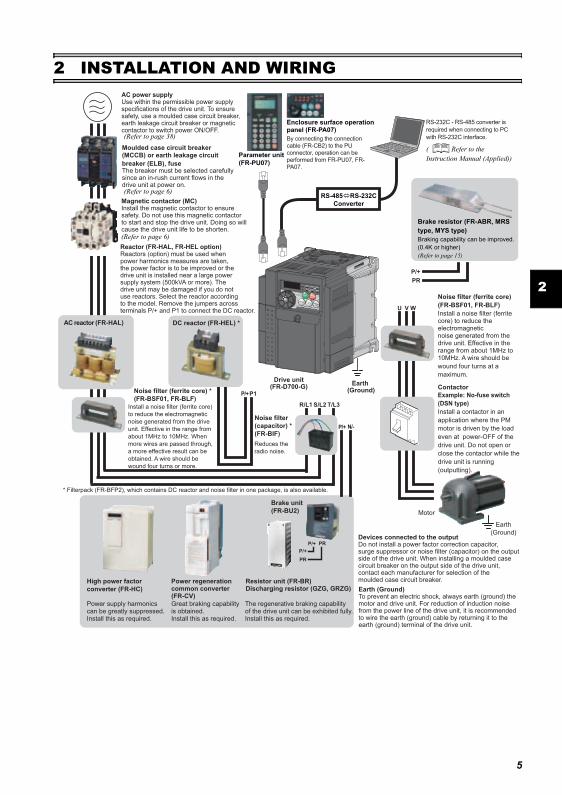
2 INSTALLATION AND WIRINGAC power supplyUse within the permissible power supply specifications of the drive unit. To ensure safety, use a moulded case circuit breaker, earth leakage circuit breaker or magnetic contactor to switch power ON/OFF.
Magnetic contactor (MC)Install the magnetic contactor to ensure safety. Do not use this magnetic contactor to start and stop the drive unit. Doing so will cause the drive unit life to be shorten.
Devices connected to the outputDo not install a power factor correction capacitor, surge suppressor or noise filter (capacitor) on the output side of the drive unit. When installing a moulded case circuit breaker on the output side of the drive unit, contact each manufacturer for selection of the moulded case circuit breaker.
The regenerative braking capability of the drive unit can be exhibited fully.Install this as required.
Power supply harmonics can be greatly suppressed.Install this as required.
High power factor
converter (FR-HC)
Power regeneration common converter (FR-CV)
R/L1 S/L2 T/L3
P1P/+
P/+ N/-
U W
P/+
PR
V
Great braking capability is obtained.Install this as required.
Reactor (FR-HAL, FR-HEL option)Reactors (option) must be used when power harmonics measures are taken, the power factor is to be improved or the drive unit is installed near a large power supply system (500kVA or more). The drive unit may be damaged if you do not use reactors. Select the reactor according to the model. Remove the jumpers across terminals P/+ and P1 to connect the DC reactor.
Noise filter (ferrite core) *
(FR-BSF01, FR-BLF)
Moulded case circuit breaker (MCCB) or earth leakage circuit
breaker (ELB), fuseThe breaker must be selected carefully since an in-rush current flows in the drive unit at power on.
Install a noise filter (ferrite core)
to reduce the electromagnetic
noise generated from the drive
unit. Effective in the range from
about 1MHz to 10MHz. When
more wires are passed through,
a more effective result can be
obtained. A wire should be
wound four turns or more.
* Filterpack (FR-BFP2), which contains DC reactor and noise filter in one package, is also available.
Earth (Ground)To prevent an electric shock, always earth (ground) the motor and drive unit. For reduction of induction noise from the power line of the drive unit, it is recommended to wire the earth (ground) cable by returning it to the earth (ground) terminal of the drive unit.
AC reactor (FR-HAL) DC reactor (FR-HEL) *
Parameter unit
(FR-PU07)
Enclosure surface operation panel (FR-PA07)
By connecting the connection
cable (FR-CB2) to the PU
connector, operation can be
performed from FR-PU07, FR-
PA07.
Noise filter
(capacitor) *
(FR-BIF)
P/+
P/+
PR
PR
Brake unit
(FR-BU2)
Reduces the
radio noise.
Resistor unit (FR-BR) Discharging resistor (GZG, GRZG)
Noise filter (ferrite core)
(FR-BSF01, FR-BLF)
Install a noise filter (ferrite core) to reduce the electromagnetic noise generated from the drive unit. Effective in the range from about 1MHz to 10MHz. A wire should be
wound four turns at a
maximum.
Contactor
Example: No-fuse switch
(DSN type)
Install a contactor in an
application where the PM
motor is driven by the load
even at power-OFF of the
drive unit. Do not open or
close the contactor while the
drive unit is running
(outputting).
RS-232C - RS-485 converter is
required when connecting to PC
with RS-232C interface.
Motor
Earth
(Ground)
Earth (Ground)
Drive unit (FR-D700-G)
RS-485 RS-232C
Converter
(Refer to page 38)
(Refer to page 6)
(Refer to page 6)
( Refer to the Instruction Manual (Applied))
Brake resistor (FR-ABR, MRS type, MYS type)Braking capability can be improved. (0.4K or higher)(Refer to page 15)
6
Peripheral devices
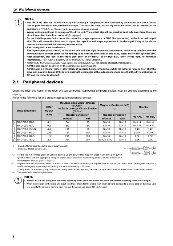
2.1 Peripheral devices
Check the drive unit model of the drive unit you purchased. Appropriate peripheral devices must be selected according to thecapacity.Refer to the following list and prepare appropriate peripheral devices.
∗1 Select a MCCB according to the power supply capacity.Install one MCCB per drive unit.
∗2 For the use in the United States or Canada, select a UL and cUL certified fuse with Class T fuse equivalent cut-offspeed or faster with the appropriate rating for branch circuit protection. Alternatively, select a UL489 molded casecircuit breaker (MCCB). (Refer to page 44)
∗3 Magnetic contactor is selected based on the AC-1 class. The electrical durability of magnetic contactor is 500,000 times. When the magnetic contactor isused for emergency stop during motor driving, the electrical durability is 25 times.If using an MC for emergency stop during motor driving, select an MC regarding the drive unit input side current as JEM1038-AC-3 class rated current.
∗4 The power factor may be slightly lower.
NOTEThe life of the drive unit is influenced by surrounding air temperature. The surrounding air temperature should be aslow as possible within the permissible range. This must be noted especially when the drive unit is installed in anenclosure. ( Refer to Chapter1 of the Instruction Manual(Applied))Wrong wiring might lead to damage of the drive unit. The control signal lines must be kept fully away from the maincircuit to protect them from noise. (Refer to page 8)Do not install a power factor correction capacitor, surge suppressor or EMC filter (capacitor) on the drive unit outputside. This will cause the drive unit to trip or the capacitor and surge suppressor to be damaged. If any of the abovedevices are connected, immediately remove them.Electromagnetic wave interferenceThe input/output (main circuit) of the drive unit includes high frequency components, which may interfere with thecommunication devices (such as AM radios) used near the drive unit. In this case, install the FR-BIF optional EMCfilter (capacitor) (for use in the input side only) or FR-BSF01 or FR-BLF EMC filter (ferrite core) to minimizeinterference. ( Refer to Chapter 3 of the Instruction Manual (Applied)).Refer to the Instruction Manual of each option and peripheral devices for details of peripheral devices.A PM motor cannot be driven by the commercial power supply.A PM motor is a magnet motor. High-voltage is generated at motor terminals while the motor is running even after thedrive unit power is turned OFF. Before closing the contactor at the output side, make sure that the drive unit power isON and the motor is stopped.
Drive unit ModelMotor Output
(kW)
Moulded Case Circuit Breaker (MCCB) ∗1
or Earth Leakage Circuit Breaker (ELB) ∗2
Magnetic Contactor (MC) ∗3
Reactor
Reactor connection Reactor connectionFR-HAL FR-HEL
without with without with
Thre
e-P
hase
200
V FR-D720-0.2K-G 0.1 5A 5A S-N10 S-N10 0.4K ∗4 0.4K ∗4FR-D720-0.4K-G 0.2 5A 5A S-N10 S-N10 0.4K ∗4 0.4K ∗4FR-D720-0.75K-G 0.4 10A 5A S-N10 S-N10 0.4K 0.4KFR-D720-1.5K-G 0.75 15A 10A S-N10 S-N10 0.75K 0.75KFR-D720-2.2K-G 1.5 20A 15A S-N10 S-N10 1.5K 1.5KFR-D720-3.7K-G 2.2 30A 30A S-N20, S-N21 S-N10 2.2K 2.2K
NOTESelect a MCCB and a magnetic contactor according to the drive unit model, and cable and reactor according to the motor output.When the breaker on the drive unit input side trips, check for the wiring fault (short circuit), damage to internal parts of the drive unit,etc. Identify the cause of the trip, then remove the cause and power ON the breaker.
MCCB Drive unit
Drive unitMCCB
IM
IM
7
Installation of the drive units and precautions
2
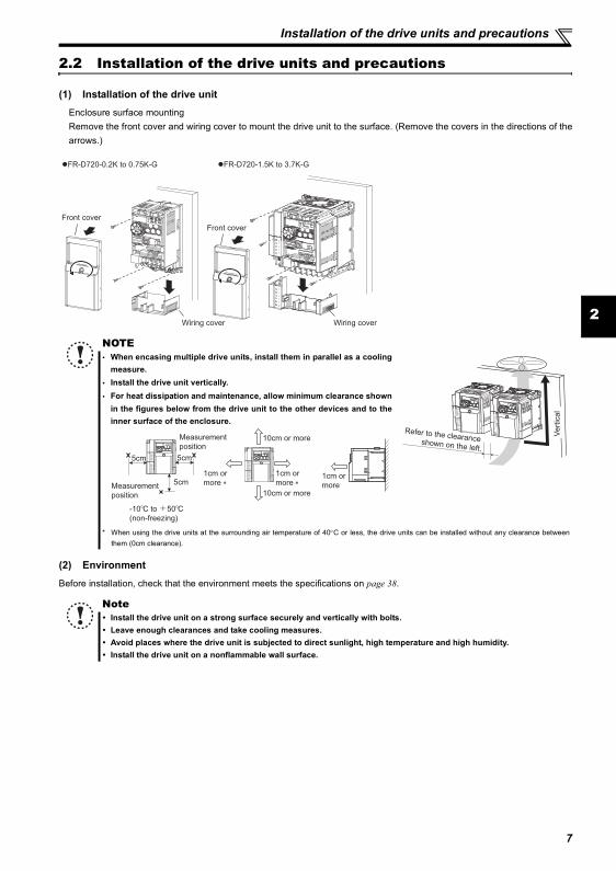
2.2 Installation of the drive units and precautions
(1) Installation of the drive unitEnclosure surface mountingRemove the front cover and wiring cover to mount the drive unit to the surface. (Remove the covers in the directions of thearrows.)
(2) Environment
Before installation, check that the environment meets the specifications on page 38.
NOTEWhen encasing multiple drive units, install them in parallel as a coolingmeasure.Install the drive unit vertically.For heat dissipation and maintenance, allow minimum clearance shownin the figures below from the drive unit to the other devices and to theinner surface of the enclosure.
* When using the drive units at the surrounding air temperature of 40°C or less, the drive units can be installed without any clearance betweenthem (0cm clearance).
NoteInstall the drive unit on a strong surface securely and vertically with bolts.Leave enough clearances and take cooling measures.Avoid places where the drive unit is subjected to direct sunlight, high temperature and high humidity.Install the drive unit on a nonflammable wall surface.
Front cover
Front cover
Wiring cover Wiring cover
�FR-D720-0.2K to 0.75K-G �FR-D720-1.5K to 3.7K-G
Vert
ical
Refer to the clearance shown on the left.
10cm or more
10cm or more
Measurement
position
Measurement
position
5cm 5cm
5cm
-10 C to +50 C
(non-freezing)
1cm or
more ∗
1cm or
more ∗
1cm or
more
8
Wiring
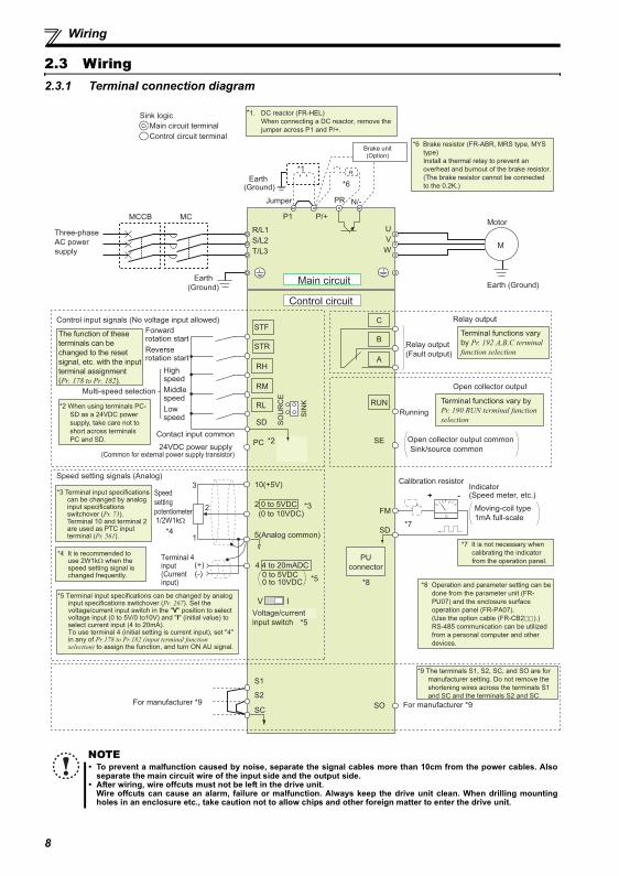
2.3 Wiring2.3.1 Terminal connection diagram
NOTETo prevent a malfunction caused by noise, separate the signal cables more than 10cm from the power cables. Alsoseparate the main circuit wire of the input side and the output side.After wiring, wire offcuts must not be left in the drive unit.Wire offcuts can cause an alarm, failure or malfunction. Always keep the drive unit clean. When drilling mountingholes in an enclosure etc., take caution not to allow chips and other foreign matter to enter the drive unit.
Earth (Ground)
Motor
M
Earth (Ground)
Three-phase
AC power
supply
MCCB MC
R/L1
P1 P/+
PR N/-
S/L2
T/L3
U
V
W
Earth
(Ground)
*6 Brake resistor (FR-ABR, MRS type, MYS
type)
Install a thermal relay to prevent an
overheat and burnout of the brake resistor.
(The brake resistor cannot be connected
to the 0.2K.)
*7 It is not necessary when
calibrating the indicator
from the operation panel.
*8 Operation and parameter setting can be
done from the parameter unit (FR-
PU07) and the enclosure surface
operation panel (FR-PA07).
(Use the option cable (FR-CB2 ).)
RS-485 communication can be utilized
from a personal computer and other
devices.
Forward rotation start
Reverse rotation start
Middle speed
High speed
Low speed
Control input signals (No voltage input allowed)
24VDC power supply (Common for external power supply transistor)
Contact input common
STR
STF
RH
RM
RL
SD
PC
Relay output
Running
Open collector output
Open collector output common
Sink/source common
RUN
SE
A
B
C
Speed setting signals (Analog)
2 0 to 5VDC
10(+5V)
2
3
1
4 4 to 20mADC
Speed
setting
potentiometer1/2W1kΩ
Terminal 4 input(Current input)
(+)(-)
5(Analog common)
*4 It is recommended to use 2W1kΩ when the speed setting signal is changed frequently.
*4
*2 When using terminals PC-
SD as a 24VDC power
supply, take care not to
short across terminals
PC and SD.
PU
connector
*1. DC reactor (FR-HEL)
When connecting a DC reactor, remove the
jumper across P1 and P/+.Control circuit terminal
Main circuit terminal
Sink logic
Jumper
*1
*6
*2
*3
*5
The function of these
terminals can be
changed to the reset
signal, etc. with the input
terminal assignment
(Pr. 178 to Pr. 182).
Multi-speed selection
Terminal functions vary by
Pr. 190 RUN terminal function
selection
Terminal functions vary
by Pr. 192 A,B,C terminal
function selection
SIN
K
SO
UR
CE
V I
*5
0 to 5VDC
(0 to 10VDC)
0 to 10VDC
*5 Terminal input specifications can be changed by analog input specifications switchover (Pr. 267). Set the voltage/current input switch in the "V" position to select voltage input (0 to 5V/0 to10V) and "I" (initial value) to select current input (4 to 20mA). To use terminal 4 (initial setting is current input), set "4" in any of Pr.178 to Pr.182 (input terminal function selection) to assign the function, and turn ON AU signal.
Voltage/current
input switch
Main circuit
Control circuit
R
Relay output
(Fault output)
Brake unit(Option)
FM
SD
Indicator(Speed meter, etc.)+ -
Moving-coil type
1mA full-scale
Calibration resistor
*7
*8
*3 Terminal input specifications can be changed by analog input specifications switchover (Pr. 73). Terminal 10 and terminal 2 are used as PTC input terminal (Pr. 561).
S1
S2
SCSO For manufacturer *9For manufacturer *9
*9 The terminals S1, S2, SC, and SO are for
manufacturer setting. Do not remove the
shortening wires across the terminals S1
and SC and the terminals S2 and SC.
Wiring
2
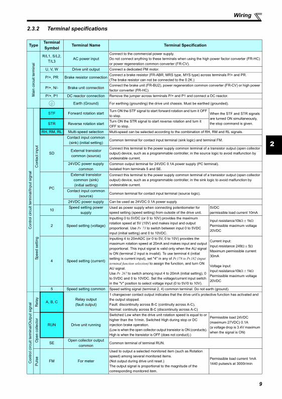
2.3.2 Terminal specifications
TypeTerminalSymbol
Terminal Name Terminal Specification
Mai
n ci
rcui
t ter
min
al
R/L1, S/L2, T/L3
AC power inputConnect to the commercial power supply. Do not connect anything to these terminals when using the high power factor converter (FR-HC) or power regeneration common converter (FR-CV).
U, V, W Drive unit output Connect a dedicated PM motor.
P/+, PR Brake resistor connection Connect a brake resistor (FR-ABR, MRS type, MYS type) across terminals P/+ and PR.(The brake resistor can not be connected to the 0.2K.)
P/+, N/- Brake unit connection Connect the brake unit (FR-BU2), power regeneration common converter (FR-CV) or high power factor converter (FR-HC).
P/+, P1 DC reactor connection Remove the jumper across terminals P/+ and P1 and connect a DC reactor.
Earth (Ground) For earthing (grounding) the drive unit chassis. Must be earthed (grounded).
Con
trol c
ircui
t ter
min
al/In
put s
igna
l
Con
tact
inpu
t
STF Forward rotation start Turn ON the STF signal to start forward rotation and turn it OFF to stop. When the STF and STR signals
are turned ON simultaneously, the stop command is given.STR Reverse rotation start Turn ON the STR signal to start reverse rotation and turn it
OFF to stop.RH, RM, RL Multi-speed selection Multi-speed can be selected according to the combination of RH, RM and RL signals.
SD
Contact input common (sink) (initial setting)
Common terminal for contact input terminal (sink logic) and terminal FM.
External transistor common (source)
Connect this terminal to the power supply common terminal of a transistor output (open collector output) device, such as a programmable controller, in the source logic to avoid malfunction by undesirable current.
24VDC power supply common
Common output terminal for 24VDC 0.1A power supply (PC terminal).Isolated from terminals 5 and SE.
PC
External transistor common (sink) (initial setting)
Connect this terminal to the power supply common terminal of a transistor output (open collector output) device, such as a programmable controller, in the sink logic to avoid malfunction by undesirable current.
Contact input common (source)
Common terminal for contact input terminal (source logic).
24VDC power supply Can be used as 24VDC 0.1A power supply.
Spee
d se
tting
10Speed setting power
supplyUsed as power supply when connecting potentiometer for speed setting (speed setting) from outside of the drive unit.
5VDCpermissible load current 10mA
2 Speed setting (voltage)
Inputting 0 to 5VDC (or 0 to 10V) provides the maximum rotation speed at 5V (10V) and makes input and output proportional. Use Pr. 73 to switch between input 0 to 5VDC input (initial setting) and 0 to 10VDC.
Input resistance10kΩ ± 1kΩPermissible maximum voltage 20VDC
4 Speed setting (current)
Inputting 4 to 20mADC (or 0 to 5V, 0 to 10V) provides the maximum rotation speed at 20mA and makes input and output proportional. This input signal is valid only when the AU signal is ON (terminal 2 input is invalid). To use terminal 4 (initial setting is current input), set "4" in any of Pr.178 to Pr.182 (input terminal function selection) to assign the function, and turn ON AU signal.Use Pr. 267 to switch among input 4 to 20mA (initial setting), 0 to 5VDC and 0 to 10VDC. Set the voltage/current input switch in the "V" position to select voltage input (0 to 5V/0 to 10V).
Current input:Input resistance 249Ω ± 5ΩMaximum permissible current 30mA
Voltage input:Input resistance10kΩ ± 1kΩPermissible maximum voltage 20VDC
5 Speed setting common Speed setting signal (terminal 2, 4) common terminal. Do not earth (ground).
Con
trol c
ircui
t ter
min
al/O
utpu
t sig
nal
Rel
ay A, B, CRelay output (fault output)
1 changeover contact output indicates that the drive unit’s protective function has activated and the output stopped.Fault: discontinuity across B-C (continuity across A-C), Normal: continuity across B-C (discontinuity across A-C)
Ope
n co
llect
or
RUN Drive unit running
Switched Low when the drive unit rotation speed is equal to or higher than the 1r/min. Switched High during stop or DC injection brake operation.(Low is when the open collector output transistor is ON (conducts). High is when the transistor is OFF (does not conduct).)
Permissible load 24VDC(maximum 27VDC) 0.1A(a voltage drop is 3.4V maximum when the signal is ON)
SEOpen collector output
commonCommon terminal of terminal RUN.
Pul
se FM For meter
Used to output a selected monitored item (such as Rotation speed) among several monitored items.(Not output during drive unit reset.)The output signal is proportional to the magnitude of the corresponding monitored item.
Permissible load current 1mA1440 pulses/s at 3000r/min
9
Wiring
Com
mun
icat
ion
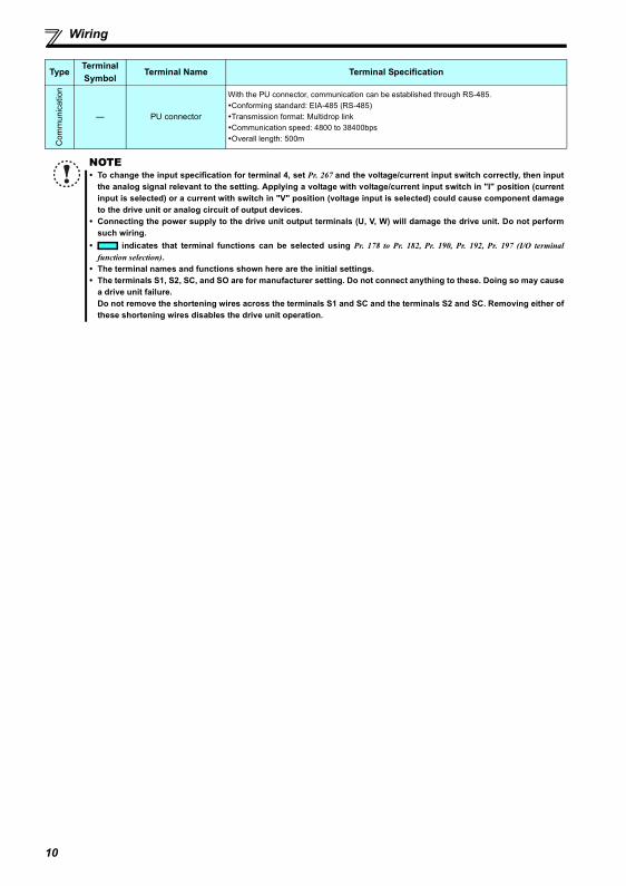
— PU connector
With the PU connector, communication can be established through RS-485.Conforming standard: EIA-485 (RS-485)Transmission format: Multidrop linkCommunication speed: 4800 to 38400bpsOverall length: 500m
NOTETo change the input specification for terminal 4, set Pr. 267 and the voltage/current input switch correctly, then inputthe analog signal relevant to the setting. Applying a voltage with voltage/current input switch in "I" position (currentinput is selected) or a current with switch in "V" position (voltage input is selected) could cause component damageto the drive unit or analog circuit of output devices.Connecting the power supply to the drive unit output terminals (U, V, W) will damage the drive unit. Do not performsuch wiring.
indicates that terminal functions can be selected using Pr. 178 to Pr. 182, Pr. 190, Pr. 192, Pr. 197 (I/O terminalfunction selection). The terminal names and functions shown here are the initial settings.The terminals S1, S2, SC, and SO are for manufacturer setting. Do not connect anything to these. Doing so may causea drive unit failure.Do not remove the shortening wires across the terminals S1 and SC and the terminals S2 and SC. Removing either ofthese shortening wires disables the drive unit operation.
TypeTerminalSymbol
Terminal Name Terminal Specification
10

11
Wiring
2
2.3.3 Terminal arrangement of the main circuit terminal, power supply and the motor wiring
Three-phase 200V class
(1) Cable size and other specifications of the main circuit terminals and the earthing terminalSelect the recommended cable size to ensure that a voltage drop will be 2% or less.If the wiring distance is long between the drive unit and motor, a main circuit cable voltage drop will cause the motor torque todecrease especially at the output of a low speed.The following table indicates a selection example for the wiring length of 20m.Three-phase 200V class (when input power supply is 220V)
∗1 The cable size is that of the cable (HIV cable (600V class 2 vinyl-insulated cable) etc.) with continuous maximum permissible temperature of 75°C. Assumesthat the surrounding air temperature is 50°C or less and the wiring distance is 20m or less.
∗2 The recommended cable size is that of the cable (THHW cable) with continuous maximum permissible temperature of 75°C. Assumes that the surroundingair temperature is 40°C or less and the wiring distance is 20m or less. (Selection example for use mainly in the United States.)
∗3 The recommended cable size is that of the cable (PVC cable) with continuous maximum permissible temperature of 70°C. Assumes that the surrounding airtemperature is 40°C or less and the wiring distance is 20m or less. (Selection example for use mainly in Europe.)
∗4 The terminal screw size indicates the terminal size for R/L1, S/L2, T/L3, U, V, W, PR, P/+, N/-, P1 and a screw for earthing (grounding).
The line voltage drop can be calculated by the following formula:
Line voltage drop [V]=
Use a larger diameter cable when the wiring distance is long or when it is desired to decrease the voltage drop (torquereduction) in the low speed range.
(2) Total wiring lengthConnect a PM motor within the total wiring length of 30m.Use one dedicated PM motor for one drive unit. Multiple PM motors cannot be connected to a drive unit.
FR-D720-0.2K to 0.75K-G FR-D720-1.5K to 3.7K-G
NOTEMake sure the power cables are connected to the R/L1, S/L2, T/L3. (Phase need not be matched.) Never connect thepower cable to the U, V, W of the drive unit. Doing so will damage the drive unit.Connect the motor to U, V, W. Turning ON the forward rotation switch (signal) at this time rotates the motorcounterclockwise when viewed from the load shaft.
Applicable Drive unitModel
Terminal ScrewSize ∗4
TighteningTorque
N·m
Crimping Terminal
Cable SizeHIV Cables, etc. (mm2) ∗1 AWG ∗2 PVC Cables, etc. (mm2) ∗3
R/L1S/L2T/L3
U, V, WR/L1S/L2T/L3
U, V, WEarthing
(grounding)cable
R/L1S/L2T/L3
U, V, WR/L1S/L2T/L3
U, V, WEarthing
(grounding)cable
FR-D720-0.2K to 0.75K-G M3.5 1.2 2-3.5 2-3.52 2 2 14 14 2.5 2.5 2.5
FR-D720-1.5K, 3.7K-G M4 1.5 2-4 2-4
NOTETighten the terminal screw to the specified torque. A screw that has been tightened too loosely can cause a short circuit ormalfunction. A screw that has been tightened too tightly can cause a short circuit or malfunction due to the unit breakage.Use crimping terminals with insulation sleeve to wire the power supply and motor.
NOTEEspecially for long-distance wiring, the drive unit may be affected by a charging current caused by the straycapacitances of the wiring, leading to a malfunction of the overcurrent protective function, fast response current limitfunction, or stall prevention function or a malfunction or fault of the equipment connected on the drive unit outputside. If malfunction of fast-response current limit function occurs, disable this function. If malfunction of stallprevention function occurs, increase the stall level. ( Refer to Pr. 22 Stall prevention operation level and Pr. 156 Stallprevention operation selection in Chapter 4 of the Instruction Manual (Applied))
MotorPower supply
N/- P/+ PR
IM
R/L1 S/L2 T/L3
Jumper
MotorPower supply
N/- P/+
PR
IM
R/L1 S/L2 T/L3
Jumper
3 × wire resistance[mΩ/m] × wiring distance[m] × current[A]
1000
Wiring
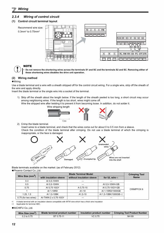
2.3.4 Wiring of control circuit(1) Control circuit terminal layout
(2) Wiring methodWiring
Use a blade terminal and a wire with a sheath stripped off for the control circuit wiring. For a single wire, strip off the sheath ofthe wire and apply directly.Insert the blade terminal or the single wire into a socket of the terminal.
1) Strip off the sheath about the length below. If the length of the sheath peeled is too long, a short circuit may occuramong neighboring wires. If the length is too short, wires might come off.Wire the stripped wire after twisting it to prevent it from becoming loose. In addition, do not solder it.
2) Crimp the blade terminal.Insert wires to a blade terminal, and check that the wires come out for about 0 to 0.5 mm from a sleeve.Check the condition of the blade terminal after crimping. Do not use a blade terminal of which the crimping isinappropriate, or the face is damaged.
Blade terminals available on the market: (as of February 2012)Phoenix Contact Co.,Ltd.
∗1 A blade terminal with an insulation sleeve compatible with MTW wire which has a thick wire insulation∗2 Applicable for terminal ABC.
NICHIFU Co.,Ltd.
Recommend wire size:0.3mm2 to 0.75mm2
NOTEDo not remove the shortening wires across the terminals S1 and SC and the terminals S2 and SC. Removing either ofthese shortening wires disables the drive unit operation.
Wire stripping length
Wire Size (mm2)Blade Terminal Model Crimping Tool
Namewith insulation sleeve without insulation sleeve for UL wire ∗1
0.3 AI 0,5-10WH — —
CRIMPFOX 6
0.5 AI 0,5-10WH — AI 0,5-10WH-GB0.75 AI 0,75-10GY A 0,75-10 AI 0,75-10GY-GB
1 AI 1-10RD A1-10 AI 1-10RD/1000GB1.25, 1.5 AI 1,5-10BK A1,5-10 AI 1,5-10BK/1000GB ∗2
0.75 (for two wires) AI-TWIN 2 x 0,75-10GY — —
Wire Size (mm2) Blade terminal product number Insulation product number Crimping Tool Product Number0.3 to 0.75 BT 0.75-11 VC 0.75 NH 69
STF STRPCSDRHRMRL
FM
CBA
10 2 5 4
RUN SE S1 S2 SCSO SD
Unstranded wires
DamagedWires are not inserted into the shellCrumpled tipSleeve
ShellW
ire
0 to 0.5mm
12
Wiring
2
Wire removal(3) Control circuit common terminals (SD, 5, SE)
Terminals SD, SE and 5 are common terminals for I/O signals.(All common terminals are isolated from each other.) Do notearth them. Avoid connecting the terminals SD and 5 and the terminals SE and 5.Terminal SD is a common terminal for the contact input terminals (STF, STR, RH, RM, RL) and pulse train output terminal(FM). The open collector circuit is isolated from the internal control circuit by photocoupler.Terminal 5 is a common terminal for the speed setting signals (terminals 2 or 4). It should be protected from external noiseusing a shielded or twisted cable.Terminal SE is a common terminal for the open collector output terminal (RUN). The contact input circuit is isolated from theinternal control circuit by photocoupler.
(4) Wiring instructions
1) It is recommended to use the cables of 0.3mm2 to 0.75mm2 gauge for connection to the control circuit terminals.2) The maximum wiring length should be 30m (200m for terminal FM).3) Do not short across terminals PC and SD. Drive unit may be damaged.4) Use two or more parallel micro-signal contacts or twin contacts to prevent
contact faults when using contact inputs since the control circuit input signalsare micro-currents.
5) Use shielded or twisted cables for connection to the control circuit terminalsand run them away from the main and power circuits (including the 200V relaysequence circuit).
6) Do not apply a voltage to the contact input terminals (e.g. STF) of the controlcircuit.
7) Always apply a voltage to the fault output terminals (A, B, C) via a relay coil, lamp, etc.
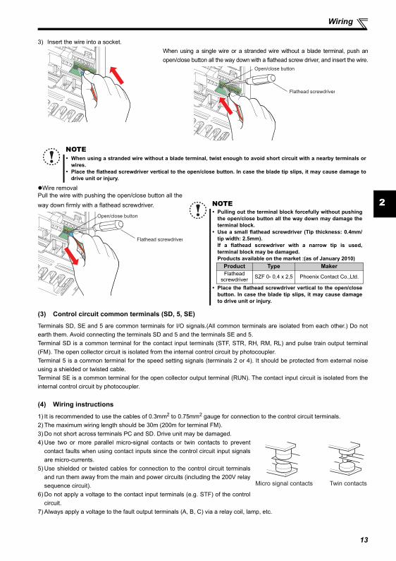
3) Insert the wire into a socket.When using a single wire or a stranded wire without a blade terminal, push anopen/close button all the way down with a flathead screw driver, and insert the wire.
NOTEWhen using a stranded wire without a blade terminal, twist enough to avoid short circuit with a nearby terminals orwires.Place the flathead screwdriver vertical to the open/close button. In case the blade tip slips, it may cause damage todrive unit or injury.
Pull the wire with pushing the open/close button all theway down firmly with a flathead screwdriver.
Open/close button
Flathead screwdriver
Open/close button
Flathead screwdriver
NOTEPulling out the terminal block forcefully without pushingthe open/close button all the way down may damage theterminal block.Use a small flathead screwdriver (Tip thickness: 0.4mm/tip width: 2.5mm). If a flathead screwdriver with a narrow tip is used,terminal block may be damaged.Products available on the market :(as of January 2010)
Place the flathead screwdriver vertical to the open/closebutton. In case the blade tip slips, it may cause damageto drive unit or injury.
Product Type MakerFlathead
screwdriver SZF 0- 0,4 x 2,5 Phoenix Contact Co.,Ltd.
Micro signal contacts Twin contacts
13
Wiring
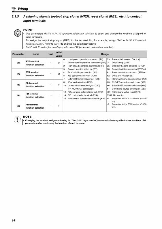
2.3.5 Assigning signals (output stop signal (MRS), reset signal (RES), etc.) to contact input terminals
POINTUse parameters (Pr.178 to Pr.182 input terminal function selection) to select and change the functions assigned toinput terminals. To assign the output stop signal (MRS) to the terminal RH, for example, assign "24" to Pr.182 RH terminalfunction selection. Refer to page 4 to change the parameter setting.Set Pr.160 Extended function display selection = "0" (extended parameters enabled).
Parameter Name UnitInitial value
Range
178STF terminal function selection
1 60
0: Low-speed operation command (RL)1: Middle-speed operation command (RM)2: High-speed operation command (RH)3: Second function selection (RT)4: Terminal 4 input selection (AU)5: Jog operation selection (JOG)7: External thermal relay input (OH)8: 15-speed selection (REX)10: Drive unit run enable signal (X10)
(FR-HC/FR-CV connection)12: PU operation external interlock (X12)14: PID control valid terminal (X14)16: PU/External operation switchover (X16)
23: Pre-excitation/servo ON (LX)24: Output stop (MRS)25: Start self-holding selection (STOP)60: Forward rotation command (STF) ∗161: Reverse rotation command (STR) ∗262: Drive unit reset (RES)64: PID forward/reverse action switchover (X64)65: PU/NET operation switchover (X65)66: External/NET operation switchover (X66)67: Command source switchover (X67)72: PID integral value reset (X72)9999: No function∗1 Assignable to the STF terminal (Pr.178)
only.∗2 Assignable to the STR terminal (Pr.179)
only.
179STR terminal function selection
1 61
180RL terminal function selection
1 0
181RM terminal function selection
1 1
182RH terminal function selection
1 2
NOTEChanging the terminal assignment using Pr.178 to Pr.182 (input terminal function selection) may affect other functions. Setparameters after confirming the function of each terminal.
14
15
Connection of a dedicated external brake resistor (MRS type, MYS type, FR-ABR) (0.4K or higher)
2
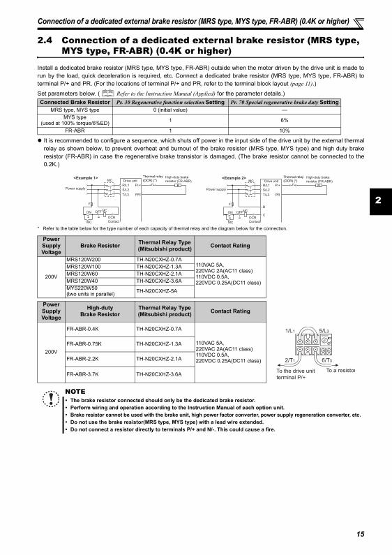
2.4 Connection of a dedicated external brake resistor (MRS type, MYS type, FR-ABR) (0.4K or higher)
Install a dedicated brake resistor (MRS type, MYS type, FR-ABR) outside when the motor driven by the drive unit is made torun by the load, quick deceleration is required, etc. Connect a dedicated brake resistor (MRS type, MYS type, FR-ABR) toterminal P/+ and PR. (For the locations of terminal P/+ and PR, refer to the terminal block layout (page 11).)
Set parameters below. ( Refer to the Instruction Manual (Applied) for the parameter details.)
It is recommended to configure a sequence, which shuts off power in the input side of the drive unit by the external thermalrelay as shown below, to prevent overheat and burnout of the brake resistor (MRS type, MYS type) and high duty brakeresistor (FR-ABR) in case the regenerative brake transistor is damaged. (The brake resistor cannot be connected to the0.2K.)
* Refer to the table below for the type number of each capacity of thermal relay and the diagram below for the connection.
Connected Brake Resistor Pr. 30 Regenerative function selection Setting Pr. 70 Special regenerative brake duty SettingMRS type, MYS type 0 (initial value) —
MYS type (used at 100% torque/6%ED) 1 6%
FR-ABR 1 10%
Power Supply Voltage
Brake Resistor Thermal Relay Type(Mitsubishi product) Contact Rating
200V
MRS120W200 TH-N20CXHZ-0.7A110VAC 5A, 220VAC 2A(AC11 class)110VDC 0.5A, 220VDC 0.25A(DC11 class)
MRS120W100 TH-N20CXHZ-1.3AMRS120W60 TH-N20CXHZ-2.1AMRS120W40 TH-N20CXHZ-3.6AMYS220W50(two units in parallel) TH-N20CXHZ-5A
Power Supply Voltage
High-dutyBrake Resistor
Thermal Relay Type(Mitsubishi product) Contact Rating
200V
FR-ABR-0.4K TH-N20CXHZ-0.7A
110VAC 5A, 220VAC 2A(AC11 class)110VDC 0.5A, 220VDC 0.25A(DC11 class)
FR-ABR-0.75K TH-N20CXHZ-1.3A
FR-ABR-2.2K TH-N20CXHZ-2.1A
FR-ABR-3.7K TH-N20CXHZ-3.6A
NOTEThe brake resistor connected should only be the dedicated brake resistor.Perform wiring and operation according to the Instruction Manual of each option unit.Brake resistor cannot be used with the brake unit, high power factor converter, power supply regeneration converter, etc.Do not use the brake resistor(MRS type, MYS type) with a lead wire extended.Do not connect a resistor directly to terminals P/+ and N/-. This could cause a fire.
MC Drive unit
MC
R
PR
P/+
S/L2
T/L3
R/L1
OFFON
OCR
Contact
Power supply
F
<Example 1>
MC
High-duty brake
resistor (FR-ABR)
Thermal relay(OCR) (*) Drive unit
MC
R
PR
P/+
S/L2
T/L3
R/L1
OFFON
B
C
Power supply
F
<Example 2>MC
High-duty brake
resistor (FR-ABR)
OCR
Contact
MC
Thermal relay(OCR) (*)
To the drive unit
terminal P/+
To a resistor
TH-N20
1/L1 5/L3
2/T1 6/T3
PRECAUTIONS FOR USE OF THE DRIVE UNIT
3 PRECAUTIONS FOR USE OF THE DRIVE UNIT
The FR-D700-G series is a highly reliable product, but incorrect peripheral circuit making or operation/handling method mayshorten the product life or damage the product.Before starting operation, always recheck the following items.
(1) Use crimping terminals with insulation sleeve to wire the power supply and motor.
(2) Application of power to the output terminals (U, V, W) of the drive unit will damage the drive unit. Never performsuch wiring.
(3) After wiring, wire offcuts must not be left in the drive unit.Wire offcuts can cause an alarm, failure or malfunction. Always keep the drive unit clean.When drilling mounting holes in an enclosure etc., take care not to allow chips and other foreign matter to enter the driveunit.
(4) Use cables of the size to make a voltage drop 2% or less.If the wiring distance is long between the drive unit and motor, a main circuit cable voltage drop will cause the motortorque to decrease especially at the output of a low speed. Refer to page 14 for the recommended wire sizes.
(5) The overall wiring length should be 30m or less.Especially for long distance wiring, or the equipment connected to the output side may malfunction or become faultyunder the influence of a charging current due to the stray capacity of the wiring. Therefore, note the overall wiring length.(Refer to page 15)
(6) Electromagnetic wave interferenceThe input/output (main circuit) of the drive unit includes high frequency components, which may interfere with thecommunication devices (such as AM radios) used near the drive unit. In this case, install the FR-BIF optional capacitortype filter (for use in the input side only) or FR-BSF01 or FR-BLF line noise filter to minimize interference.
(7) Do not install a power factor correction capacitor, surge suppressor or capacitor type filter on the drive unitoutput side.This will cause the drive unit to trip or the capacitor and surge suppressor to be damaged. If any of the above devices areconnected, immediately remove them.
(8) For some short time after the power is switched OFF, a high voltage remains in the smoothing capacitor.When accessing the drive unit for inspection, wait for at least 10 minutes after the power supply has been switched OFF,and then make sure that the voltage across the main circuit terminals P/+ and N/- of the drive unit is not more than30VDC using a tester, etc.
(9) A short circuit or earth (ground) fault on the drive unit output side may damage the drive unit module.Fully check the insulation resistance of the circuit prior to drive unit operation since repeated short circuits caused byperipheral circuit inadequacy or an earth (ground) fault caused by wiring inadequacy or reduced motor insulationresistance may damage the drive unit module.Fully check the to-earth (ground) insulation and phase to phase insulation of the drive unit output side before power-On.Especially for an old motor or use in hostile atmosphere, securely check the motor insulation resistance etc.
(10) Do not use the drive unit input side magnetic contactor to start/stop the drive unit.Since repeated inrush currents at power ON will shorten the life of the converter circuit (switching life is about 1,000,000times.), frequent starts and stops of the MC must be avoided. Turn ON/OFF the drive unit start controlling terminals (STF,STR) to run/stop the drive unit. ( Refer to the Instruction Manual (Applied))
(11) Across terminals P/+ and PR, connect only an external brake resistor.Do not connect a mechanical brake.The brake resistor cannot be connected to the 0.2K. Do not connect anything to terminals P/+ and PR. Also, never short between these terminals.
16
PRECAUTIONS FOR USE OF THE DRIVE UNIT
3
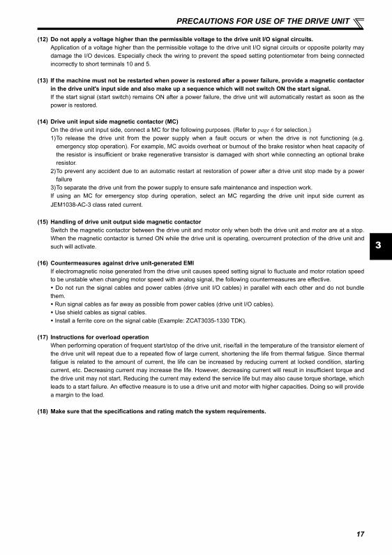
(12) Do not apply a voltage higher than the permissible voltage to the drive unit I/O signal circuits.Application of a voltage higher than the permissible voltage to the drive unit I/O signal circuits or opposite polarity maydamage the I/O devices. Especially check the wiring to prevent the speed setting potentiometer from being connectedincorrectly to short terminals 10 and 5.
(13) If the machine must not be restarted when power is restored after a power failure, provide a magnetic contactorin the drive unit's input side and also make up a sequence which will not switch ON the start signal.If the start signal (start switch) remains ON after a power failure, the drive unit will automatically restart as soon as thepower is restored.
(14) Drive unit input side magnetic contactor (MC)On the drive unit input side, connect a MC for the following purposes. (Refer to page 6 for selection.)1)To release the drive unit from the power supply when a fault occurs or when the drive is not functioning (e.g.
emergency stop operation). For example, MC avoids overheat or burnout of the brake resistor when heat capacity ofthe resistor is insufficient or brake regenerative transistor is damaged with short while connecting an optional brakeresistor.
2)To prevent any accident due to an automatic restart at restoration of power after a drive unit stop made by a powerfailure
3)To separate the drive unit from the power supply to ensure safe maintenance and inspection work. If using an MC for emergency stop during operation, select an MC regarding the drive unit input side current asJEM1038-AC-3 class rated current.
(15) Handling of drive unit output side magnetic contactorSwitch the magnetic contactor between the drive unit and motor only when both the drive unit and motor are at a stop.When the magnetic contactor is turned ON while the drive unit is operating, overcurrent protection of the drive unit andsuch will activate.
(16) Countermeasures against drive unit-generated EMIIf electromagnetic noise generated from the drive unit causes speed setting signal to fluctuate and motor rotation speedto be unstable when changing motor speed with analog signal, the following countermeasures are effective. Do not run the signal cables and power cables (drive unit I/O cables) in parallel with each other and do not bundle
them. Run signal cables as far away as possible from power cables (drive unit I/O cables). Use shield cables as signal cables. Install a ferrite core on the signal cable (Example: ZCAT3035-1330 TDK).
(17) Instructions for overload operationWhen performing operation of frequent start/stop of the drive unit, rise/fall in the temperature of the transistor element ofthe drive unit will repeat due to a repeated flow of large current, shortening the life from thermal fatigue. Since thermalfatigue is related to the amount of current, the life can be increased by reducing current at locked condition, startingcurrent, etc. Decreasing current may increase the life. However, decreasing current will result in insufficient torque andthe drive unit may not start. Reducing the current may extend the service life but may also cause torque shortage, whichleads to a start failure. An effective measure is to use a drive unit and motor with higher capacities. Doing so will providea margin to the load.
(18) Make sure that the specifications and rating match the system requirements.
17
18
4 FAILSAFE OF THE SYSTEM WHICH USES THE DRIVE UNIT
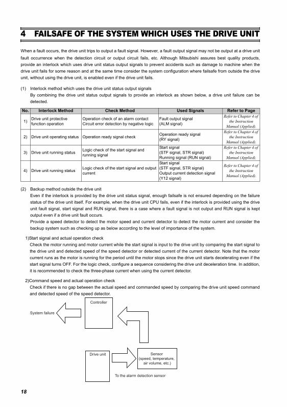
When a fault occurs, the drive unit trips to output a fault signal. However, a fault output signal may not be output at a drive unitfault occurrence when the detection circuit or output circuit fails, etc. Although Mitsubishi assures best quality products,provide an interlock which uses drive unit status output signals to prevent accidents such as damage to machine when thedrive unit fails for some reason and at the same time consider the system configuration where failsafe from outside the driveunit, without using the drive unit, is enabled even if the drive unit fails.
(1) Interlock method which uses the drive unit status output signals By combining the drive unit status output signals to provide an interlock as shown below, a drive unit failure can bedetected.
(2) Backup method outside the drive unitEven if the interlock is provided by the drive unit status signal, enough failsafe is not ensured depending on the failurestatus of the drive unit itself. For example, when the drive unit CPU fails, even if the interlock is provided using the driveunit fault signal, start signal and RUN signal, there is a case where a fault signal is not output and RUN signal is keptoutput even if a drive unit fault occurs.Provide a speed detector to detect the motor speed and current detector to detect the motor current and consider thebackup system such as checking up as below according to the level of importance of the system.
1)Start signal and actual operation checkCheck the motor running and motor current while the start signal is input to the drive unit by comparing the start signal tothe drive unit and detected speed of the speed detector or detected current of the current detector. Note that the motorcurrent runs as the motor is running for the period until the motor stops since the drive unit starts decelerating even if thestart signal turns OFF. For the logic check, configure a sequence considering the drive unit deceleration time. In addition,it is recommended to check the three-phase current when using the current detector.
2)Command speed and actual operation checkCheck if there is no gap between the actual speed and commanded speed by comparing the drive unit speed commandand detected speed of the speed detector.
No. Interlock Method Check Method Used Signals Refer to Page
1) Drive unit protective function operation
Operation check of an alarm contactCircuit error detection by negative logic
Fault output signal (ALM signal)
Refer to Chapter 4 of the Instruction
Manual (Applied).
2) Drive unit operating status Operation ready signal check Operation ready signal (RY signal)
Refer to Chapter 4 of the Instruction
Manual (Applied).
3) Drive unit running status Logic check of the start signal and running signal
Start signal (STF signal, STR signal)Running signal (RUN signal)
Refer to Chapter 4 of the Instruction
Manual (Applied).
4) Drive unit running status Logic check of the start signal and output current
Start signal (STF signal, STR signal)Output current detection signal (Y12 signal)
Refer to Chapter 4 of the Instruction
Manual (Applied).
Drive unit
Controller
System failure
To the alarm detection sensor
Sensor
(speed, temperature,
air volume, etc.)
Start/stop from the operation panel (PU operation)
5
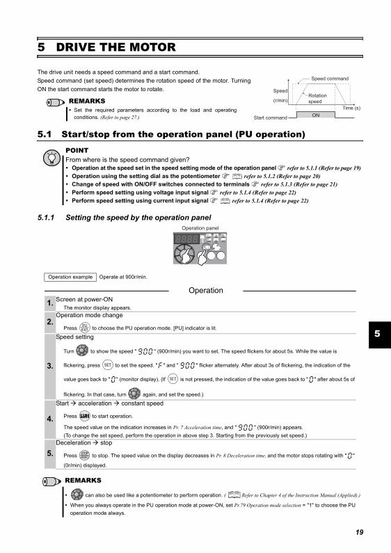
5 DRIVE THE MOTOR
5.1 Start/stop from the operation panel (PU operation)
5.1.1 Setting the speed by the operation panel
The drive unit needs a speed command and a start command. Speed command (set speed) determines the rotation speed of the motor. TurningON the start command starts the motor to rotate.
POINTFrom where is the speed command given?
Operation at the speed set in the speed setting mode of the operation panel refer to 5.1.1 (Refer to page 19)Operation using the setting dial as the potentiometer refer to 5.1.2 (Refer to page 20) Change of speed with ON/OFF switches connected to terminals refer to 5.1.3 (Refer to page 21) Perform speed setting using voltage input signal refer to 5.1.4 (Refer to page 22) Perform speed setting using current input signal refer to 5.1.4 (Refer to page 22)
Operation example Operate at 900r/min.
Operation 1. Screen at power-ON
The monitor display appears.
2.Operation mode change
Press to choose the PU operation mode. [PU] indicator is lit.
3.
Speed setting
Turn to show the speed " " (900r/min) you want to set. The speed flickers for about 5s. While the value is
flickering, press to set the speed. " " and " " flicker alternately. After about 3s of flickering, the indication of the
value goes back to " " (monitor display). (If is not pressed, the indication of the value goes back to " " after about 5s of
flickering. In that case, turn again, and set the speed.)
4.
Start acceleration constant speed
Press to start operation.
The speed value on the indication increases in Pr. 7 Acceleration time, and " " (900r/min) appears. (To change the set speed, perform the operation in above step 3. Starting from the previously set speed.)
5.Deceleration stop
Press to stop. The speed value on the display decreases in Pr. 8 Deceleration time, and the motor stops rotating with " "
(0r/min) displayed.
REMARKS
can also be used like a potentiometer to perform operation. ( Refer to Chapter 4 of the Instruction Manual (Applied).)
When you always operate in the PU operation mode at power-ON, set Pr.79 Operation mode selection = "1" to choose the PU operation mode always.
REMARKSSet the required parameters according to the load and operatingconditions. (Refer to page 27.) ON
Speed
Time (s)
(r/min)
Start command
Speed command
Rotation
speed
Operation panel
19
Start/stop from the operation panel (PU operation)
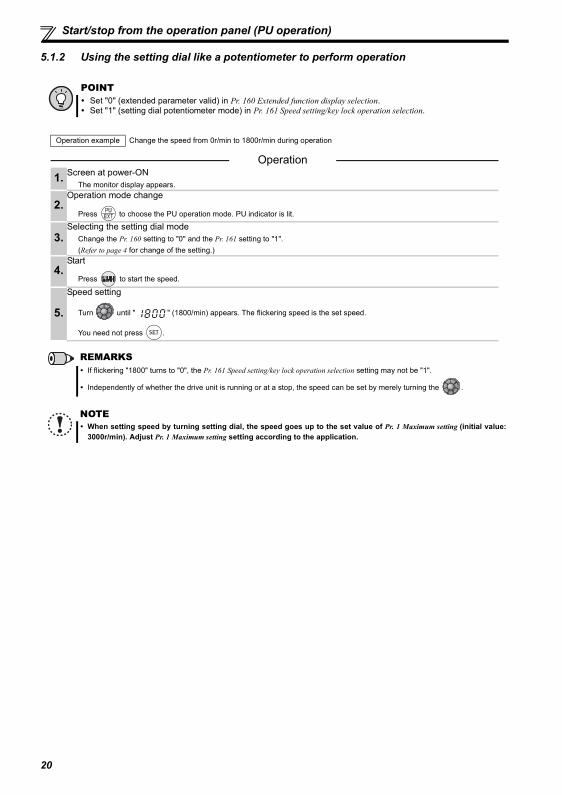
5.1.2 Using the setting dial like a potentiometer to perform operation
POINTSet "0" (extended parameter valid) in Pr. 160 Extended function display selection.Set "1" (setting dial potentiometer mode) in Pr. 161 Speed setting/key lock operation selection.
Operation example Change the speed from 0r/min to 1800r/min during operation
Operation 1. Screen at power-ON
The monitor display appears.
2.Operation mode change
Press to choose the PU operation mode. PU indicator is lit.
3.Selecting the setting dial mode
Change the Pr. 160 setting to "0" and the Pr. 161 setting to "1".(Refer to page 4 for change of the setting.)
4.Start
Press to start the speed.
5.
Speed setting
Turn until " " (1800/min) appears. The flickering speed is the set speed.
You need not press .
REMARKSIf flickering "1800" turns to "0", the Pr. 161 Speed setting/key lock operation selection setting may not be "1".
Independently of whether the drive unit is running or at a stop, the speed can be set by merely turning the .
NOTEWhen setting speed by turning setting dial, the speed goes up to the set value of Pr. 1 Maximum setting (initial value:3000r/min). Adjust Pr. 1 Maximum setting setting according to the application.
20
Start/stop from the operation panel (PU operation)
5
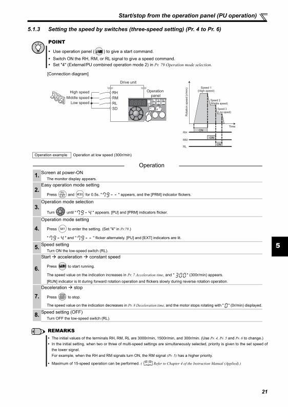
5.1.3 Setting the speed by switches (three-speed setting) (Pr. 4 to Pr. 6)
POINT
Use operation panel ( ) to give a start command.
Switch ON the RH, RM, or RL signal to give a speed command.Set "4" (External/PU combined operation mode 2) in Pr. 79 Operation mode selection.
[Connection diagram]
Operation example Operation at low speed (300r/min)
Operation
1. Screen at power-ONThe monitor display appears.
2.Easy operation mode setting
Press and for 0.5s. " " appears, and the [PRM] indicator flickers.
3.Operation mode selection
Turn until " " appears. [PU] and [PRM] indicators flicker.
4.Operation mode setting
Press to enter the setting. (Set "4" in Pr.79.)
" " and " " flicker alternately. [PU] and [EXT] indicators are lit.
5. Speed settingTurn ON the low-speed switch (RL).
6.
Start acceleration constant speed
Press to start running.
The speed value on the indication increases in Pr. 7 Acceleration time, and " " (300r/min) appears.
[RUN] indicator is lit during forward rotation operation and flickers slowly during reverse rotation operation.
7.Deceleration stop
Press to stop.
The speed value on the indication decreases in Pr. 8 Deceleration time, and the motor stops rotating with " " (0r/min) displayed.
8. Speed setting (OFF)Turn OFF the low-speed switch (RL).
REMARKSThe initial values of the terminals RH, RM, RL are 3000r/min, 1500r/min, and 300r/min. (Use Pr. 4, Pr. 5 and Pr. 6 to change.)In the initial setting, when two or three of multi-speed settings are simultaneously selected, priority is given to the set speed ofthe lower signal.For example, when the RH and RM signals turn ON, the RM signal (Pr. 5) has a higher priority.
Maximum of 15-speed operation can be performed. ( Refer to Chapter 4 of the Instruction Manual (Applied).)
SD
RH
RM
RL
Drive unit
Operation
panelHigh speed
Middle speed
Low speed
ON
ON
ON
Ro
tatio
n s
pe
ed
(r/
min
) Speed 1(High speed)
Speed 2(Middle speed)
Speed 3(Low speed)
RH
RM
RL
Time
21
Start/stop from the operation panel (PU operation)
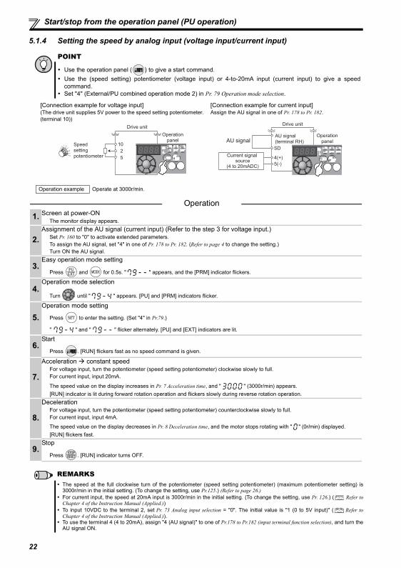
5.1.4 Setting the speed by analog input (voltage input/current input)
POINT
Use the operation panel ( ) to give a start command.Use the (speed setting) potentiometer (voltage input) or 4-to-20mA input (current input) to give a speedcommand.Set "4" (External/PU combined operation mode 2) in Pr. 79 Operation mode selection.
[Connection example for voltage input] [Connection example for current input](The drive unit supplies 5V power to the speed setting potentiometer. (terminal 10))
Assign the AU signal in one of Pr. 178 to Pr. 182.
Operation example Operate at 3000r/min.
Operation 1. Screen at power-ON
The monitor display appears.
2.Assignment of the AU signal (current input) (Refer to the step 3 for voltage input.)
Set Pr. 160 to "0" to activate extended parameters. To assign the AU signal, set "4" in one of Pr. 178 to Pr. 182. (Refer to page 4 to change the setting.) Turn ON the AU signal.
3.Easy operation mode setting
Press and for 0.5s. " " appears, and the [PRM] indicator flickers.
4.Operation mode selection
Turn until " " appears. [PU] and [PRM] indicators flicker.
5.Operation mode setting
Press to enter the setting. (Set "4" in Pr.79.)
" " and " " flicker alternately. [PU] and [EXT] indicators are lit.
6.Start
Press . [RUN] flickers fast as no speed command is given.
7.
Acceleration constant speedFor voltage input, turn the potentiometer (speed setting potentiometer) clockwise slowly to full. For current input, input 20mA.
The speed value on the display increases in Pr. 7 Acceleration time, and " " (3000r/min) appears.[RUN] indicator is lit during forward rotation operation and flickers slowly during reverse rotation operation.
8.
DecelerationFor voltage input, turn the potentiometer (speed setting potentiometer) counterclockwise slowly to full. For current input, input 4mA.
The speed value on the display decreases in Pr. 8 Deceleration time, and the motor stops rotating with " " (0r/min) displayed.[RUN] flickers fast.
9.Stop
Press . [RUN] indicator turns OFF.
REMARKSThe speed at the full clockwise turn of the potentiometer (speed setting potentiometer) (maximum potentiometer setting) is3000r/min in the initial setting. (To change the setting, use Pr.125.) (Refer to page 26.)For current input, the speed at 20mA input is 3000r/min in the initial setting. (To change the setting, use Pr. 126.) ( Refer toChapter 4 of the Instruction Manual (Applied.))To input 10VDC to the terminal 2, set Pr. 73 Analog input selection = "0". The initial value is "1 (0 to 5V input)" ( Refer toChapter 4 of the Instruction Manual (Applied.)). To use the terminal 4 (4 to 20mA), assign "4 (AU signal)" to one of Pr.178 to Pr.182 (input terminal function selection), and turn theAU signal ON.
5
10
2
Speed
setting
potentiometer
Drive unit
Operation
panel
5(-)
4(+)
SD
Drive unit
Operation
panelAU signal
Current signal source
(4 to 20mADC)
AU signal
(terminal RH)
22
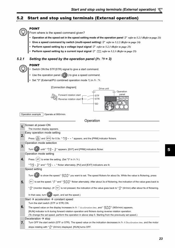
Start and stop using terminals (External operation)
5
5.2 Start and stop using terminals (External operation)
5.2.1 Setting the speed by the operation panel (Pr. 79 = 3)
POINTFrom where is the speed command given?
Operation at the speed set in the speed setting mode of the operation panel refer to 5.2.1 (Refer to page 23)
Give a speed command by switch (multi-speed setting) refer to 5.2.2 (Refer to page 24)
Perform speed setting by a voltage input signal refer to 5.2.3 (Refer to page 25)
Perform speed setting by a current input signal refer to 5.2.3 (Refer to page 25)
POINTSwitch ON the STF(STR) signal to give a start command.
Use the operation panel ( ) to give a speed command.
Set "3" (External/PU combined operation mode 1) in Pr. 79.
Operation example Operate at 900r/min.
Operation
1. Screen at power-ONThe monitor display appears.
2.Easy operation mode setting
Press and for 0.5s. " " appears, and the [PRM] indicator flickers.
3.Operation mode selection
Turn until " " appears. [EXT] and [PRM] indicators flicker.
4.Operation mode setting
Press to enter the setting. (Set "3" in Pr.79.)
" " and " " flicker alternately. [PU] and [EXT] indicators are lit.
5.
Speed setting
Turn to show the speed " " you want to set. The speed flickers for about 5s. While the value is flickering, press
to set the speed. " " and " " flicker alternately. After about 3s of flickering, the indication of the value goes back to
" " (monitor display). (If is not pressed, the indication of the value goes back to " " (0r/min) after about 5s of flickering.
In that case, turn again, and set the speed.)
6.
Start acceleration constant speedTurn the start switch (STF or STR) ON.
The speed value on the display increases in Pr. 7 Acceleration time, and " " (900r/min) appears.[RUN] indicator is lit during forward rotation operation and flickers during reverse rotation operation.(To change the set speed, perform the operation in above step 5. Starting from the previously set speed.)
7.Deceleration stop
Turn OFF the start switch (STF or STR). The speed value on the indication decreases in Pr. 8 Deceleration time, and the motor
stops rotating with " " (0r/min) displayed. [RUN] turns OFF.
SD
STF
STR
Drive unit
Operation
panelForward rotation start
Reverse rotation start
[Connection diagram]
23
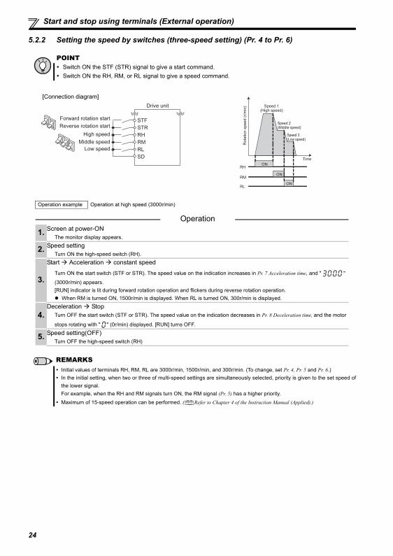
Start and stop using terminals (External operation)
5.2.2 Setting the speed by switches (three-speed setting) (Pr. 4 to Pr. 6)
POINTSwitch ON the STF (STR) signal to give a start command.Switch ON the RH, RM, or RL signal to give a speed command.
Operation example Operation at high speed (3000r/min)
Operation
1. Screen at power-ONThe monitor display appears.
2. Speed settingTurn ON the high-speed switch (RH).
3.
Start Acceleration constant speed
Turn ON the start switch (STF or STR). The speed value on the indication increases in Pr. 7 Acceleration time, and " "
(3000r/min) appears.[RUN] indicator is lit during forward rotation operation and flickers during reverse rotation operation.
When RM is turned ON, 1500r/min is displayed. When RL is turned ON, 300r/min is displayed.
4.Deceleration Stop
Turn OFF the start switch (STF or STR). The speed value on the indication decreases in Pr. 8 Deceleration time, and the motor
stops rotating with " " (0r/min) displayed. [RUN] turns OFF.
5. Speed setting(OFF)Turn OFF the high-speed switch (RH)
REMARKSInitial values of terminals RH, RM, RL are 3000r/min, 1500r/min, and 300r/min. (To change, set Pr. 4, Pr. 5 and Pr. 6.)In the initial setting, when two or three of multi-speed settings are simultaneously selected, priority is given to the set speed ofthe lower signal.For example, when the RH and RM signals turn ON, the RM signal (Pr. 5) has a higher priority.Maximum of 15-speed operation can be performed. ( Refer to Chapter 4 of the Instruction Manual (Applied).)
Drive unit
Forward rotation startReverse rotation start
High speed
RM
STFSTRRH
Middle speedLow speed
SDRL
[Connection diagram]
ON
ON
ON
Ro
tatio
n s
pe
ed
(r/
min
) Speed 1(High speed)
Speed 2(Middle speed)
Speed 3(Low speed)
RH
RM
RL
Time
24
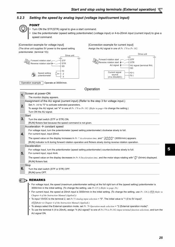
Start and stop using terminals (External operation)
5
5.2.3 Setting the speed by analog input (voltage input/current input)
POINTTurn ON the STF(STR) signal to give a start command.Use the potentiometer (speed setting potentiometer) (voltage input) or 4-to-20mA input (current input) to give aspeed command.
[Connection example for voltage input] [Connection example for current input](The drive unit supplies 5V power to the speed setting potentiometer. (terminal 10))
Assign the AU signal in one of Pr. 178 to Pr. 182.
Operation example Operate at 3000r/min.
Operation
1. Screen at power-ONThe monitor display appears.
2.Assignment of the AU signal (current input) (Refer to the step 3 for voltage input.)
Set Pr. 160 to "0" to activate extended parameters. To assign the AU signal, set "4" in one of Pr. 178 to Pr. 182. (Refer to page 4 to change the setting.)Turn ON the AU signal.
3.Start
Turn the start switch (STF or STR) ON.[RUN] flickers fast because the speed command is not given.
4.
Acceleration constant speedFor voltage input, turn the potentiometer (speed setting potentiometer) clockwise slowly to full. For current input, input 20mA.
The speed value on the display increases in Pr. 7 Acceleration time, and " " (3000r/min) appears.
[RUN] indicator is lit during forward rotation operation and flickers slowly during reverse rotation operation.
5.
DecelerationFor voltage input, turn the potentiometer (speed setting potentiometer) counterclockwise slowly to full. For current input, input 4mA.
The speed value on the display decreases in Pr. 8 Deceleration time, and the motor stops rotating with " " (0r/min) displayed. [RUN] flickers fast.
6.Stop
Turn the start switch (STF or STR) OFF. [RUN] turns OFF.
REMARKSFor voltage input, the speed (maximum potentiometer setting) at the full right turn of the (speed setting) potentiometer is 3000r/min in the initial setting. (To change the setting, use Pr.125.) (Refer to page 26.)
For current input, the speed at 20mA input is 3000r/min in the initial setting. (To change the setting, use Pr. 126.) ( Refer toChapter 4 of the Instruction Manual (Applied.))To input 10VDC to the terminal 2, set Pr.73 Analog input selection = "0". The initial value is "1 (0 to 5V input)".( Refer to Chapter 4 of the Instruction Manual (Applied).)To always select the External operation mode, set Pr. 79 Operation mode selection = "2 (External operation mode)".To use the terminal 4 (4 to 20mA), assign "4 (AU signal)" to one of Pr.178 to Pr.182 (input terminal function selection), and turn theAU signal ON.
Speed setting
potentiometer
Drive unit
5
10
2
Forward rotation start
Reverse rotation start
STF
STR
SD
Drive unit
5(-)
4(+)
SD
AU signal (terminal RH)AU signal
Forward rotation start
Reverse rotation start
STF
STR
Current signal source
(4 to 20mADC)
25
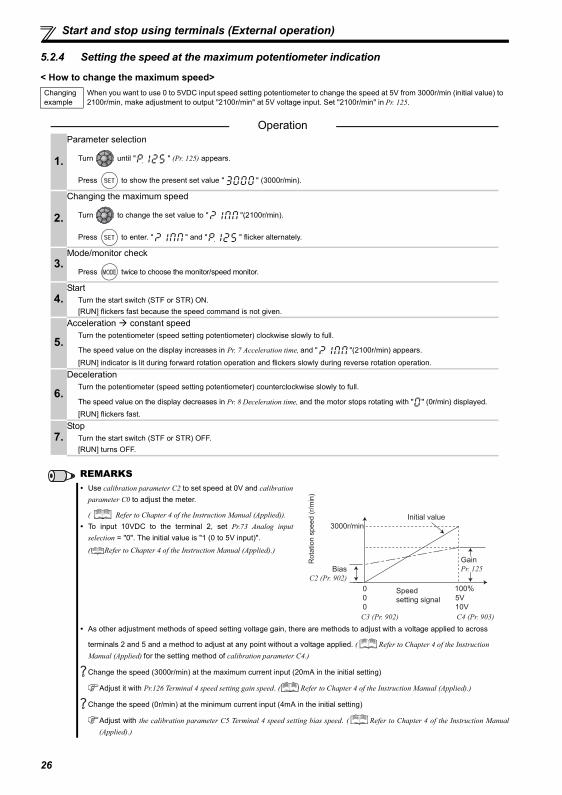
Start and stop using terminals (External operation)
5.2.4 Setting the speed at the maximum potentiometer indication
< How to change the maximum speed>Changing example
When you want to use 0 to 5VDC input speed setting potentiometer to change the speed at 5V from 3000r/min (initial value) to 2100r/min, make adjustment to output "2100r/min" at 5V voltage input. Set "2100r/min" in Pr. 125.
Operation
1.
Parameter selection
Turn until " " (Pr. 125) appears.
Press to show the present set value " " (3000r/min).
2.
Changing the maximum speed
Turn to change the set value to " "(2100r/min).
Press to enter. " " and " " flicker alternately.
3.Mode/monitor check
Press twice to choose the monitor/speed monitor.
4.Start
Turn the start switch (STF or STR) ON.[RUN] flickers fast because the speed command is not given.
5.
Acceleration constant speedTurn the potentiometer (speed setting potentiometer) clockwise slowly to full.
The speed value on the display increases in Pr. 7 Acceleration time, and " "(2100r/min) appears.
[RUN] indicator is lit during forward rotation operation and flickers slowly during reverse rotation operation.
6.
DecelerationTurn the potentiometer (speed setting potentiometer) counterclockwise slowly to full.
The speed value on the display decreases in Pr. 8 Deceleration time, and the motor stops rotating with " " (0r/min) displayed. [RUN] flickers fast.
7.Stop
Turn the start switch (STF or STR) OFF. [RUN] turns OFF.
REMARKSUse calibration parameter C2 to set speed at 0V and calibrationparameter C0 to adjust the meter.
( Refer to Chapter 4 of the Instruction Manual (Applied)).To input 10VDC to the terminal 2, set Pr.73 Analog inputselection = "0". The initial value is "1 (0 to 5V input)".( Refer to Chapter 4 of the Instruction Manual (Applied).)
As other adjustment methods of speed setting voltage gain, there are methods to adjust with a voltage applied to across
terminals 2 and 5 and a method to adjust at any point without a voltage applied. ( Refer to Chapter 4 of the Instruction Manual (Applied) for the setting method of calibration parameter C4.)
Change the speed (3000r/min) at the maximum current input (20mA in the initial setting)
Adjust it with Pr.126 Terminal 4 speed setting gain speed. ( Refer to Chapter 4 of the Instruction Manual (Applied).)
Change the speed (0r/min) at the minimum current input (4mA in the initial setting)
Adjust with the calibration parameter C5 Terminal 4 speed setting bias speed. ( Refer to Chapter 4 of the Instruction Manual(Applied).)
Initial value
Bias
C2 (Pr. 902)
0
0
Speed
setting signal
100%
10V
0 5V
C3 (Pr. 902) C4 (Pr. 903)
Gain
Pr. 125
Rota
tion s
peed (
r/m
in)
3000r/min
26
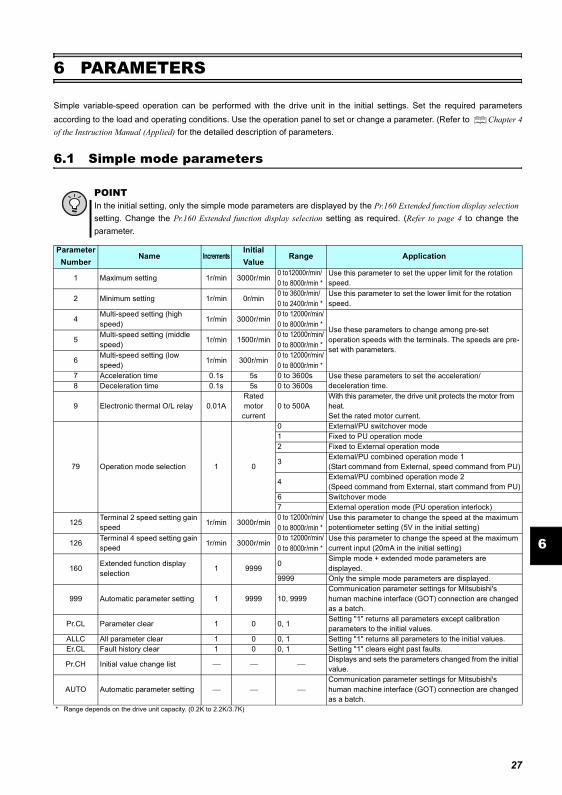
Simple mode parameters
6
6 PARAMETERS
Simple variable-speed operation can be performed with the drive unit in the initial settings. Set the required parametersaccording to the load and operating conditions. Use the operation panel to set or change a parameter. (Refer to Chapter 4of the Instruction Manual (Applied) for the detailed description of parameters.
6.1 Simple mode parameters
POINTIn the initial setting, only the simple mode parameters are displayed by the Pr.160 Extended function display selectionsetting. Change the Pr.160 Extended function display selection setting as required. (Refer to page 4 to change theparameter.
Parameter Number
Name IncrementsInitial Value
Range Application
1 Maximum setting 1r/min 3000r/min0 to12000r/min/0 to 8000r/min *
Use this parameter to set the upper limit for the rotation speed.
2 Minimum setting 1r/min 0r/min0 to 3600r/min/0 to 2400r/min *
Use this parameter to set the lower limit for the rotation speed.
4Multi-speed setting (high speed) 1r/min 3000r/min
0 to 12000r/min/0 to 8000r/min *
Use these parameters to change among pre-set operation speeds with the terminals. The speeds are pre-set with parameters.
5Multi-speed setting (middle speed) 1r/min 1500r/min
0 to 12000r/min/0 to 8000r/min *
6Multi-speed setting (low speed) 1r/min 300r/min
0 to 12000r/min/0 to 8000r/min *
7 Acceleration time 0.1s 5s 0 to 3600s Use these parameters to set the acceleration/deceleration time.8 Deceleration time 0.1s 5s 0 to 3600s
9 Electronic thermal O/L relay 0.01ARatedmotor current
0 to 500AWith this parameter, the drive unit protects the motor from heat. Set the rated motor current.
79 Operation mode selection 1 0
0 External/PU switchover mode1 Fixed to PU operation mode2 Fixed to External operation mode
3 External/PU combined operation mode 1(Start command from External, speed command from PU)
4 External/PU combined operation mode 2(Speed command from External, start command from PU)
6 Switchover mode7 External operation mode (PU operation interlock)
125 Terminal 2 speed setting gain speed 1r/min 3000r/min
0 to 12000r/min/0 to 8000r/min *
Use this parameter to change the speed at the maximum potentiometer setting (5V in the initial setting)
126 Terminal 4 speed setting gain speed 1r/min 3000r/min
0 to 12000r/min/0 to 8000r/min *
Use this parameter to change the speed at the maximum current input (20mA in the initial setting)
160 Extended function display selection
1 9999 0Simple mode + extended mode parameters are displayed.
9999 Only the simple mode parameters are displayed.
999 Automatic parameter setting 1 9999 10, 9999Communication parameter settings for Mitsubishi's human machine interface (GOT) connection are changed as a batch.
Pr.CL Parameter clear 1 0 0, 1 Setting "1" returns all parameters except calibration parameters to the initial values.
ALLC All parameter clear 1 0 0, 1 Setting "1" returns all parameters to the initial values.Er.CL Fault history clear 1 0 0, 1 Setting "1" clears eight past faults.
Pr.CH Initial value change list ⎯ ⎯ ⎯Displays and sets the parameters changed from the initial value.
AUTO Automatic parameter setting ⎯ ⎯ ⎯Communication parameter settings for Mitsubishi's human machine interface (GOT) connection are changed as a batch.
* Range depends on the drive unit capacity. (0.2K to 2.2K/3.7K)
27
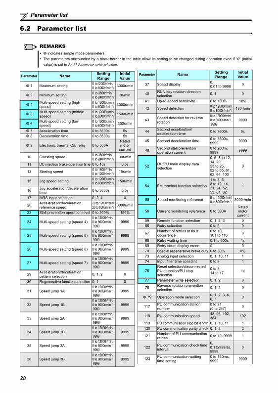
Parameter list
6.2 Parameter list
REMARKS indicates simple mode parameters.
The parameters surrounded by a black border in the table allow its setting to be changed during operation even if "0" (initialvalue) is set in Pr. 77 Parameter write selection.
Parameter Name Setting Range
Initial Value
1 Maximum setting 0 to12000r/min/0 to 8000r/min *1
3000r/min
2 Minimum setting 0 to 3600r/min/0 to 2400r/min *1
0r/min
4 Multi-speed setting (high speed)
0 to 12000r/min/0 to 8000r/min *1
3000r/min
5 Multi-speed setting (middle speed)
0 to 12000r/min/0 to 8000r/min *1
1500r/min
6 Multi-speed setting (low speed)
0 to 12000r/min/0 to 8000r/min *1
300r/min
7 Acceleration time 0 to 3600s 5s 8 Deceleration time 0 to 3600s 5s
9 Electronic thermal O/L relay 0 to 500ARated motor current
10 Coasting speed 0 to 3600r/min/0 to 2400r/min *1
90r/min
11 DC injection brake operation time 0 to 10s 0.5s
13 Starting speed 0 to 1800r/min/0 to 1200r/min *1
15r/min
15 Jog speed setting 0 to 12000r/min/0 to 8000r/min *1
150r/min
16 Jog acceleration/deceleration time 0 to 3600s 0.5s
17 MRS input selection 0, 2, 4 0
20 Acceleration/deceleration reference speed
30 to 12000r/min/20 to 8000r/min *1
3000r/min
22 Stall prevention operation level 0 to 200% 150%
24 Multi-speed setting (speed 4)0 to 12000r/min/0 to 8000r/min *1, 9999
9999
25 Multi-speed setting (speed 5)0 to 12000r/min/0 to 8000r/min *1, 9999
9999
26 Multi-speed setting (speed 6)0 to 12000r/min/0 to 8000r/min *1, 9999
9999
27 Multi-speed setting (speed 7)0 to 12000r/min/0 to 8000r/min *1, 9999
9999
29 Acceleration/deceleration pattern selection 0, 1, 2 0
30 Regenerative function selection 0, 1 0
31 Speed jump 1A0 to 12000r/min/0 to 8000r/min *1, 9999
9999
32 Speed jump 1B0 to 12000r/min/0 to 8000r/min *1, 9999
9999
33 Speed jump 2A0 to 12000r/min/0 to 8000r/min *1, 9999
9999
34 Speed jump 2B0 to 12000r/min/0 to 8000r/min *1, 9999
9999
35 Speed jump 3A0 to 12000r/min/0 to 8000r/min *1, 9999
9999
36 Speed jump 3B0 to 12000r/min/0 to 8000r/min *1, 9999
9999
37 Speed display 0, 0.01 to 9998 0
40 RUN key rotation direction selection 0, 1 0
41 Up-to-speed sensitivity 0 to 100% 10%
42 Speed detection 0 to 12000r/min/0 to 8000r/min *1
180r/min
43 Speed detection for reverse rotation
0 to 12000r/min/0 to 8000r/min *1, 9999
9999
44 Second acceleration/deceleration time 0 to 3600s 5s
45 Second deceleration time 0 to 3600s, 9999 9999
48 Second stall prevention operation current
0 to 200%, 9999 9999
52 DU/PU main display data selection
0, 5, 8 to 12, 14, 20, 23 to 25, 52 to 55, 61, 62, 64, 100
0
54 FM terminal function selection
1 to 3, 5, 8 to 12, 14, 21, 24, 52, 53, 61, 62
1
55 Speed monitoring reference 0 to 12000r/min/0 to 8000r/min *1
3000r/min
56 Current monitoring reference 0 to 500ARated motor current
59 Remote function selection 0, 1, 2, 3 065 Retry selection 0 to 5 0
67 Number of retries at fault occurrence
0 to 10, 101 to 110 0
68 Retry waiting time 0.1 to 600s 1s69 Retry count display erase 0 070 Special regenerative brake duty 0 to 30% 0%73 Analog input selection 0, 1, 10, 11 174 Input filter time constant 0 to 8 1
75Reset selection/disconnected PU detection/PU stop selection
0 to 3, 14 to 17 14
77 Parameter write selection 0, 1, 2 0
78 Reverse rotation prevention selection 0, 1, 2 0
79 Operation mode selection 0, 1, 2, 3, 4, 6, 7 0
117 PU communication station number
0 to 31 (0 to 247) 0
118 PU communication speed 48, 96, 192, 384 192
119 PU communication stop bit length 0, 1, 10, 11 1120 PU communication parity check 0, 1, 2 2
121 Number of PU communication retries 0 to 10, 9999 1
122 PU communication check time interval
0, 0.1 to 999.8s, 9999
0
123 PU communication waiting time setting
0 to 150ms, 9999 9999
Parameter Name Setting Range
Initial Value
28

Parameter list
6
124 PU communication CR/LF selection 0, 1, 2 1
125 Terminal 2 speed setting gain speed
0 to 12000r/min/0 to 8000r/min *1
3000r/min
126 Terminal 4 speed setting gain speed
0 to 12000r/min/0 to 8000r/min *1
3000r/min
127 PID control automatic switchover speed
0 to 12000r/min/0 to 8000r/min *1, 9999
9999
128 PID action selection 0, 20, 21 0
129 PID proportional band 0.1 to 1000%, 9999 100%
130 PID integral time 0.1 to 3600s, 9999 1s
131 PID upper limit 0 to 100%, 9999 9999
132 PID lower limit 0 to 100%, 9999 9999
133 PID action set point 0 to 100%, 9999 9999
134 PID differential time 0.01 to 10s, 9999 9999
144 Speed setting switchover
2, 4, 6, 8, 10, 102, 104, 106, 108, 110
104/106 *1
145 PU display language selection 0 to 7 0150 Output current detection level 0 to 200% 150%
151 Output current detection signal delay time 0 to 10s 0s
152 Zero current detection level 0 to 200% 5%153 Zero current detection time 0 to 1s 0.5s
156 Stall prevention operation selection
0 to 31, 100, 101 0
157 OL signal output timer 0 to 25s, 9999 0s
160 Extended function display selection 0, 9999 9999
161 Speed setting/key lock operation selection 0, 1, 10, 11 0
166 Output current detection signal retention time
0 to 10s, 9999 0.1s
167 Output current detection operation selection 0, 1 0
168Parameter for manufacturer setting. Do not set.
169170 Watt-hour meter clear 0, 10, 9999 9999171 Operation hour meter clear 0, 9999 9999
178 STF terminal function selection0 to 5, 7, 8, 10, 12, 14,16, 23 to 25, 60(Pr.178),61(Pr.179),62, 64 to 67,72, 9999
60
179 STR terminal function selection 61
180 RL terminal function selection 0
181 RM terminal function selection 1
182 RH terminal function selection 2
Parameter Name Setting Range
Initial Value
190 RUN terminal function selection
0, 1, 3, 4, 7, 8, 11 to 16, 21, 25, 26, 33, 47, 48, 64, 70, 79, 90, 91, 93(Pr.190), 95, 96, 98 to 101, 103, 104, 107, 108, 111 to 116, 121, 125, 126, 133, 147, 148, 164, 170, 179, 190, 191, 193(Pr.190), 195, 196, 198, 199, 9999
0
192 A,B,C terminal function selection 99
232 Multi-speed setting (speed 8)0 to 12000r/min/0 to 8000r/min *1, 9999
9999
233 Multi-speed setting (speed 9)0 to 12000r/min/0 to 8000r/min *1, 9999
9999
234 Multi-speed setting (speed 10)0 to 12000r/min/0 to 8000r/min *1, 9999
9999
235 Multi-speed setting (speed 11)0 to 12000r/min/0 to 8000r/min *1, 9999
9999
236 Multi-speed setting (speed 12)0 to 12000r/min/0 to 8000r/min *1, 9999
9999
237 Multi-speed setting (speed 13)0 to 12000r/min/0 to 8000r/min *1, 9999
9999
238 Multi-speed setting (speed 14)0 to 12000r/min/0 to 8000r/min *1, 9999
9999
239 Multi-speed setting (speed 15)0 to 12000r/min/0 to 8000r/min *1, 9999
9999
241 Analog input display unit switchover 0, 1 0
244 Cooling fan operation selection 0, 1 1
249 Earth (ground) fault detection at start 0, 1 0
250 Stop selection
0 to 100s, 1000 to 1100s, 8888, 9999
9999
251 Output phase loss protection selection 0, 1 1
255 Life alarm status display (0 to 15) 0
256 Inrush current limit circuit life display (0 to 100%) 100%
257 Control circuit capacitor life display (0 to 100%) 100%258 Main circuit capacitor life display (0 to 100%) 100%
259 Main circuit capacitor life measuring
0, 1 (2, 3, 8, 9) 0
267 Terminal 4 input selection 0, 1, 2 0268 Monitor decimal digits selection 0, 1, 9999 9999269 Parameter for manufacturer setting. Do not set.
295 Magnitude of speed change setting
0, 0.01, 0.10, 1.00, 10.00 0
296 Password lock level1 to 6, 101 to 106, 9999
9999
Parameter Name Setting Range
Initial Value
29
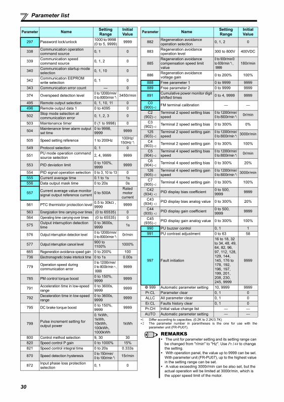
Parameter list
∗1 Differ according to capacities. (0.2K to 2.2K/3.7K)∗2 The parameter number in parentheses is the one for use with the
parameter unit (FR-PU07).
297 Password lock/unlock 1000 to 9998 (0 to 5, 9999) 9999
338 Communication operation command source 0, 1 0
339 Communication speed command source 0, 1, 2 0
340 Communication startup mode selection 0, 1, 10 0
342 Communication EEPROM write selection 0, 1 0
343 Communication error count — 0
374 Overspeed detection level 0 to 12000r/min/0 to 8000r/min *1
3450r/min
495 Remote output selection 0, 1, 10, 11 0496 Remote output data 1 0 to 4095 0
502 Stop mode selection at communication error 0, 1, 2, 3 0
503 Maintenance timer 0 (1 to 9998) 0
504 Maintenance timer alarm output set time
0 to 9998, 9999 9999
505 Speed setting reference 1 to 200Hz 100Hz/150Hz *1
549 Protocol selection 0, 1 0
551 PU mode operation command source selection 2, 4, 9999 9999
553 PID deviation limit 0 to 100%, 9999 9999
554 PID signal operation selection 0 to 3, 10 to 13 0555 Current average time 0.1 to 1s 1s556 Data output mask time 0 to 20s 0s
557 Current average value monitor signal output reference current 0 to 500A
Rated motor current
561 PTC thermistor protection level 0.5 to 30kΩ , 9999 9999
563 Energization time carrying-over times (0 to 65535) 0564 Operating time carrying-over times (0 to 65535) 0
575 Output interruption detection time
0 to 3600s, 9999 1s
576 Output interruption detection level 0 to 12000r/min/0 to 8000r/min *1
0r/min
577 Output interruption cancel level 900 to 1100% 1000%
665 Regeneration avoidance speed gain 0 to 200% 100736 Electromagnetic brake interlock time 0 to 1s 0.00s
779 Operation speed during communication error
0 to 12000r/min/0 to 8000r/min *1, 9999
9999
785 PM control torque boost 0 to 150%, 9999 9999
791 Acceleration time in low-speed range
0 to 3600s, 9999 9999
792 Deceleration time in low-speed range
0 to 3600s, 9999 9999
795 DC brake torque boost 0 to 150%, 9999 9999
799 Pulse increment setting for output power
0.1kWh, 1kWh, 10kWh, 100kWh, 1000kWh
1kWh
800 Control method selection 9, 30 30820 Speed control P gain 0 to 1000% 15%821 Speed control integral time 0 to 20s 0.333s
870 Speed detection hysteresis 0 to 150r/min/0 to 100r/min *1
15r/min
872 Input phase loss protection selection 0, 1 0
Parameter Name Setting Range
Initial Value
882 Regeneration avoidance operation selection 0, 1, 2 0
883 Regeneration avoidance operation level 300 to 800V 400VDC
885Regeneration avoidance compensation speed limit value
0 to 900r/min/0 to 600r/min *1, 9999
180r/min
886 Regeneration avoidance voltage gain 0 to 200% 100%
888 Free parameter 1 0 to 9999 9999889 Free parameter 2 0 to 9999 9999
891 Cumulative power monitor digit shifted times 0 to 4, 9999 9999
C0(900) ∗2
FM terminal calibration — —
C2(902) ∗2
Terminal 2 speed setting bias speed
0 to 12000r/min/0 to 8000r/min *1
0r/min
C3(902) ∗2
Terminal 2 speed setting bias 0 to 300% 0%
125(903) ∗2
Terminal 2 speed setting gain speed
0 to 12000r/min/0 to 8000r/min *1
3000r/min
C4(903) ∗2
Terminal 2 speed setting gain 0 to 300% 100%
C5(904) ∗2
Terminal 4 speed setting bias speed
0 to 12000r/min/0 to 8000r/min *1
0r/min
C6(904) ∗2
Terminal 4 speed setting bias 0 to 300% 20%
126(905) ∗2
Terminal 4 speed setting gain speed
0 to 12000r/min/0 to 8000r/min *1
3000r/min
C7(905) ∗2
Terminal 4 speed setting gain 0 to 300% 100%
C42
(934) ∗2PID display bias coefficient 0 to 500,
9999 9999
C43 (934) ∗2
PID display bias analog value 0 to 300% 20%
C44
(935) ∗2PID display gain coefficient 0 to 500,
9999 9999
C45(935) ∗2
PID display gain analog value 0 to 300% 100%
990 PU buzzer control 0, 1 1991 PU contrast adjustment 0 to 63 58
997 Fault initiation
16 to 18, 32 to 34, 48, 49, 64, 82, 96, 97, 112, 128, 129, 144, 145, 176 to 178, 192, 196, 197, 199, 201, 208, 230, 245, 9999
9999
999 Automatic parameter setting 10, 9999 9999Pr.CL Parameter clear 0, 1 0ALLC All parameter clear 0, 1 0Er.CL Faults history clear 0, 1 0Pr.CH Initial value change list — —AUTO Automatic parameter setting — —
REMARKS The unit for parameter setting and its setting range can be changed from "r/min" to "Hz". Use Pr.144 to change the setting. With operation panel, the value up to 9999 can be set. With parameter unit (FR-PU07), up to the highest value in the setting range can be set. A value exceeding 3000r/min can be also set, but the actual operation will be limited at 3000r/min, which is the upper speed limit of the motor.
Parameter Name Setting Range
Initial Value
30
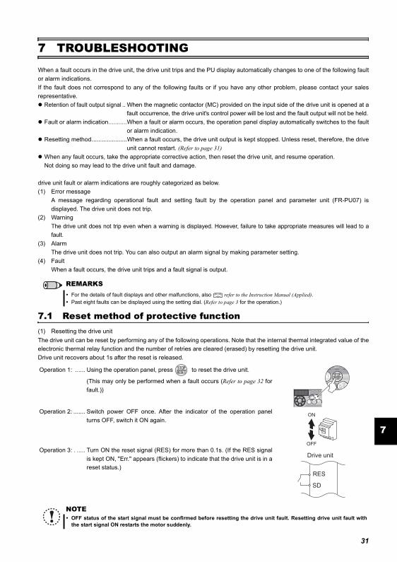
Reset method of protective function
7
7 TROUBLESHOOTINGWhen a fault occurs in the drive unit, the drive unit trips and the PU display automatically changes to one of the following faultor alarm indications.If the fault does not correspond to any of the following faults or if you have any other problem, please contact your salesrepresentative.
Retention of fault output signal .. When the magnetic contactor (MC) provided on the input side of the drive unit is opened at afault occurrence, the drive unit's control power will be lost and the fault output will not be held.
Fault or alarm indication...........When a fault or alarm occurs, the operation panel display automatically switches to the faultor alarm indication.
Resetting method.....................When a fault occurs, the drive unit output is kept stopped. Unless reset, therefore, the driveunit cannot restart. (Refer to page 31)
When any fault occurs, take the appropriate corrective action, then reset the drive unit, and resume operation.Not doing so may lead to the drive unit fault and damage.
drive unit fault or alarm indications are roughly categorized as below.(1) Error message
A message regarding operational fault and setting fault by the operation panel and parameter unit (FR-PU07) isdisplayed. The drive unit does not trip.
(2) WarningThe drive unit does not trip even when a warning is displayed. However, failure to take appropriate measures will lead to afault.
(3) AlarmThe drive unit does not trip. You can also output an alarm signal by making parameter setting.
(4) FaultWhen a fault occurs, the drive unit trips and a fault signal is output.
7.1 Reset method of protective function(1) Resetting the drive unitThe drive unit can be reset by performing any of the following operations. Note that the internal thermal integrated value of theelectronic thermal relay function and the number of retries are cleared (erased) by resetting the drive unit.Drive unit recovers about 1s after the reset is released.
REMARKSFor the details of fault displays and other malfunctions, also refer to the Instruction Manual (Applied).Past eight faults can be displayed using the setting dial. (Refer to page 3 for the operation.)
Operation 1: ...... Using the operation panel, press to reset the drive unit.
(This may only be performed when a fault occurs (Refer to page 32 forfault.))
Operation 2: ....... Switch power OFF once. After the indicator of the operation panelturns OFF, switch it ON again.
Operation 3: . ..... Turn ON the reset signal (RES) for more than 0.1s. (If the RES signalis kept ON, "Err." appears (flickers) to indicate that the drive unit is in areset status.)
NOTEOFF status of the start signal must be confirmed before resetting the drive unit fault. Resetting drive unit fault withthe start signal ON restarts the motor suddenly.
ON
OFF
SD
Drive unit
RES
31

List of fault displays
7.2 List of fault displaysWhen a fault occurs, the drive unit trips and the PU display automatically changes to one of the following fault or alarm indications.The error message shows an operational error. The drive unit output is not shut off.Warnings are messages given before faults occur. The drive unit output is not shut off.Alarms warn the operator of failures with output signals. The drive unit output is not shut off.When faults occur, the protective functions are activated to drive unit trip and output the fault signals.
Function Name Description Countermeasure Display
Erro
r mes
sage
Operation panel lockOperation has been attempted during the operation panel lock. Press for 2s to release lock.
Password lockedReading/writing of a password-restricted parameter has been attempted.
Enter the password in Pr. 297 Password lock/unlock to unlock the password function before operating.
Write disable error
Parameter setting has been attempted although parameter writing is set to be disabled. Overlapping range has been set for the speed jump.PU and the drive unit cannot make normal communication.
Check the setting of Pr. 77 Parameter write selection.
Check the setting of Pr. 31 to Pr. 36 (speed jump).Check the connection of PU and the drive unit.
Write error during operation
Parameter writing has been attempted while a value other than "2" is set in Pr. 77 Parameter write selection and the STF (STR) is ON.
Set "2" in Pr. 77 Parameter write selection.After stopping the operation, set parameters.
Calibration errorAnalog input bias and gain calibration values have been set too close.
Check the settings of calibration parameters C3, C4, C6 and C7 (calibration functions).
Mode designation error
Parameter setting has been attempted in the External or NET operation mode when Pr. 77 Parameter write selection is not "2."Parameter writing has been attempted when the command source is not at the operation panel.
After setting the operation mode to the "PU operation mode", set parameters. Set "2" in Pr. 77 Parameter write selection.Remove the parameter unit (FR-PU07), then set the Pr. 551 PU mode operation command source selection = "9999 (initial setting)."Set Pr. 551 PU mode operation command source selection = "4."
Drive unit resetThe reset signal (RES signal) is ON.(drive unit output is shutoff.)
Turn OFF the reset command.
War
ning
Stall prevention (overcurrent)
The overcurrent stall prevention has been activated.
Set Pr.7 Acceleration time and Pr.8 Deceleration time longer.Reduce the loadSet the stall prevention operation current in Pr. 22 Stall prevention operation level. (The acceleration/deceleration time may change.)Increase the stall prevention operation level with Pr. 22 Stall prevention operation level, or disable stall prevention with Pr. 156 Stall prevention operation selection. (Operation at OL occurrence can be selected using Pr. 156 Stall prevention operation selection. )Check the connection of the PM motor.
Stall prevention (overvoltage)
The overvoltage stall prevention function or the regeneration avoidance function has been activated.(This warning is also output during the regeneration avoidance operation.)
Set the deceleration time longer.
Regenerative brake pre-alarm *2
The regenerative brake duty has reached 85% of the Pr. 70 Special regenerative brake duty setting or higher.
Set the deceleration time longer.Check the Pr.30 Regenerative function selection and Pr. 70 Special regenerative brake duty settings.
Electronic thermal relay function pre-alarm *1
The cumulative value of the electronic thermal O/L relay has reached 85% of the Pr. 9 Electronicthermal O/L relay setting or higher.
Reduce the load and frequency of operation.Set an appropriate value in Pr. 9 Electronic thermal O/L relay.
PU stop on the operation panel has been pressed
during the External operation.Turn the start signal OFF and release with .
Maintenance signal output *2
The cumulative energization time has exceeded the maintenance output timer set value.
Setting "0" in Pr. 503 Maintenance timer erases the signal.
UndervoltageThe voltage at the main circuit power has been lowered.
Investigate the devices on the power supply line such as the power supply itself.
SAThe shorting wire across the terminals S1 and SC or the terminals S2 and SC is disconnected.
Short across the terminals S1 and SC and the terminals S2 and SC with shortening wires.
Ala
rm Fan alarmThe cooling fan is at a standstill although it is required to be operated. Cooling fan speed has decelerated.
Check for fan failure. Please contact your sales representative.
32
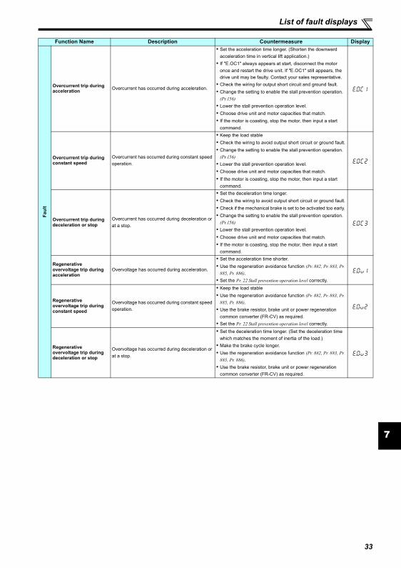
List of fault displays
7
Faul
t
Overcurrent trip during acceleration Overcurrent has occurred during acceleration.
Set the acceleration time longer. (Shorten the downward acceleration time in vertical lift application.)If "E.OC1" always appears at start, disconnect the motor once and restart the drive unit. If "E.OC1" still appears, the drive unit may be faulty. Contact your sales representative.Check the wiring for output short circuit and ground fault.Change the setting to enable the stall prevention operation. (Pr.156)Lower the stall prevention operation level.Choose drive unit and motor capacities that match.If the motor is coasting, stop the motor, then input a start command.
Overcurrent trip during constant speed
Overcurrent has occurred during constant speed operation.
Keep the load stableCheck the wiring to avoid output short circuit or ground fault.Change the setting to enable the stall prevention operation. (Pr.156)Lower the stall prevention operation level.Choose drive unit and motor capacities that match. If the motor is coasting, stop the motor, then input a start command.
Overcurrent trip during deceleration or stop
Overcurrent has occurred during deceleration or at a stop.
Set the deceleration time longer.Check the wiring to avoid output short circuit or ground fault.Check if the mechanical brake is set to be activated too early. Change the setting to enable the stall prevention operation. (Pr.156)Lower the stall prevention operation level.Choose drive unit and motor capacities that match. If the motor is coasting, stop the motor, then input a start command.
Regenerative overvoltage trip during acceleration
Overvoltage has occurred during acceleration.
Set the acceleration time shorter.Use the regeneration avoidance function (Pr. 882, Pr. 883, Pr. 885, Pr. 886).Set the Pr. 22 Stall prevention operation level correctly.
Regenerative overvoltage trip during constant speed
Overvoltage has occurred during constant speed operation.
Keep the load stableUse the regeneration avoidance function (Pr. 882, Pr. 883, Pr. 885, Pr. 886).Use the brake resistor, brake unit or power regeneration common converter (FR-CV) as required.Set the Pr. 22 Stall prevention operation level correctly.
Regenerative overvoltage trip during deceleration or stop
Overvoltage has occurred during deceleration or at a stop.
Set the deceleration time longer. (Set the deceleration time which matches the moment of inertia of the load.)Make the brake cycle longer.Use the regeneration avoidance function (Pr. 882, Pr. 883, Pr. 885, Pr. 886).Use the brake resistor, brake unit or power regeneration common converter (FR-CV) as required.
Function Name Description Countermeasure Display
33
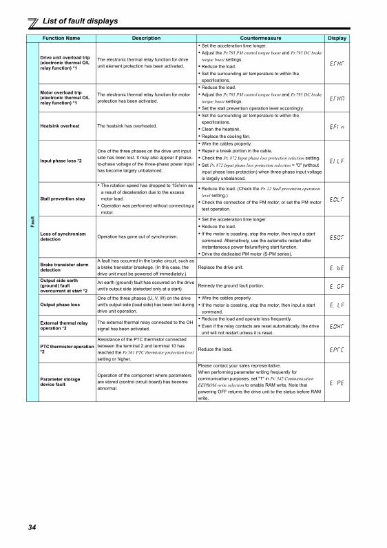
List of fault displays
Fault
Drive unit overload trip (electronic thermal O/L relay function) *1
The electronic thermal relay function for drive unit element protection has been activated.
Set the acceleration time longer.Adjust the Pr.785 PM control torque boost and Pr.795 DC brake torque boost settings.Reduce the load.Set the surrounding air temperature to within the specifications.
Motor overload trip(electronic thermal O/L relay function) *1
The electronic thermal relay function for motor protection has been activated.
Reduce the load.Adjust the Pr.785 PM control torque boost and Pr.795 DC brake torque boost settings.Set the stall prevention operation level accordingly.
Heatsink overheat The heatsink has overheated.
Set the surrounding air temperature to within the specifications.Clean the heatsink.Replace the cooling fan.
Input phase loss *2
One of the three phases on the drive unit input side has been lost. It may also appear if phase-to-phase voltage of the three-phase power input has become largely unbalanced.
Wire the cables properly.Repair a break portion in the cable.Check the Pr. 872 Input phase loss protection selection setting.Set Pr. 872 Input phase loss protection selection = "0" (without input phase loss protection) when three-phase input voltage is largely unbalanced.
Stall prevention stop
The rotation speed has dropped to 15r/min as a result of deceleration due to the excess motor load.Operation was performed without connecting a motor.
Reduce the load. (Check the Pr. 22 Stall prevention operation level setting.)Check the connection of the PM motor, or set the PM motor test operation.
Loss of synchronism detection Operation has gone out of synchronism.
Set the acceleration time longer.Reduce the load.If the motor is coasting, stop the motor, then input a start command. Alternatively, use the automatic restart after instantaneous power failure/flying start function. Drive the dedicated PM motor (S-PM series).
Brake transistor alarm detection
A fault has occurred in the brake circuit, such as a brake transistor breakage. (In this case, the drive unit must be powered off immediately.)
Replace the drive unit.
Output side earth (ground) fault overcurrent at start *2
An earth (ground) fault has occurred on the drive unit's output side (detected only at a start).
Remedy the ground fault portion.
Output phase lossOne of the three phases (U, V, W) on the drive unit's output side (load side) has been lost during drive unit operation.
Wire the cables properly.If the motor is coasting, stop the motor, then input a start command.
External thermal relay operation *2
The external thermal relay connected to the OH signal has been activated.
Reduce the load and operate less frequently.Even if the relay contacts are reset automatically, the drive unit will not restart unless it is reset.
PTC thermistor operation *2
Resistance of the PTC thermistor connected between the terminal 2 and terminal 10 has reached the Pr.561 PTC thermistor protection level setting or higher.
Reduce the load.
Parameter storage device fault
Operation of the component where parameters are stored (control circuit board) has become abnormal.
Please contact your sales representative.When performing parameter writing frequently for communication purposes, set "1" in Pr. 342 Communication EEPROM write selection to enable RAM write. Note that powering OFF returns the drive unit to the status before RAM write.
Function Name Description Countermeasure Display
34
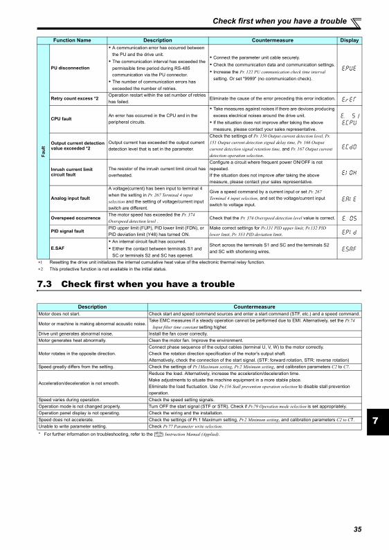
Check first when you have a trouble
7
7.3 Check first when you have a trouble
Faul
t
PU disconnection
A communication error has occurred between the PU and the drive unit.The communication interval has exceeded the permissible time period during RS-485 communication via the PU connector. The number of communication errors has exceeded the number of retries.
Connect the parameter unit cable securely.Check the communication data and communication settings.Increase the Pr. 122 PU communication check time interval setting. Or set "9999" (no communication check).
Retry count excess *2Operation restart within the set number of retries has failed.
Eliminate the cause of the error preceding this error indication.
CPU faultAn error has occurred in the CPU and in the peripheral circuits.
Take measures against noises if there are devices producing excess electrical noises around the drive unit.If the situation does not improve after taking the above measure, please contact your sales representative.
/
Output current detection value exceeded *2
Output current has exceeded the output current detection level that is set in the parameter.
Check the settings of Pr. 150 Output current detection level, Pr. 151 Output current detection signal delay time, Pr. 166 Output current detection signal retention time, and Pr. 167 Output current detection operation selection.
Inrush current limit circuit fault
The resistor of the inrush current limit circuit has overheated.
Configure a circuit where frequent power ON/OFF is not repeated. If the situation does not improve after taking the above measure, please contact your sales representative.
Analog input fault
A voltage(current) has been input to terminal 4 when the setting in Pr. 267 Terminal 4 input selection and the setting of voltage/current input switch are different.
Give a speed command by a current input or set Pr. 267 Terminal 4 input selection, and set the voltage/current input switch to voltage input.
Overspeed occurrenceThe motor speed has exceeded the Pr. 374 Overspeed detection level .
Check that the Pr. 374 Overspeed detection level value is correct.
PID signal faultPID upper limit (FUP), PID lower limit (FDN), or PID deviation limit (Y48) has turned ON.
Make correct settings for Pr.131 PID upper limit, Pr.132 PID lower limit, Pr. 553 PID deviation limit.
E.SAFAn internal circuit fault has occurred.Either the contact between terminals S1 and SC or terminals S2 and SC has opened.
Short across the terminals S1 and SC and the terminals S2 and SC with shortening wires.
∗1 Resetting the drive unit initializes the internal cumulative heat value of the electronic thermal relay function.∗2 This protective function is not available in the initial status.
Description CountermeasureMotor does not start. Check start and speed command sources and enter a start command (STF, etc.) and a speed command.
Motor or machine is making abnormal acoustic noise.Take EMC measures if a steady operation cannot be performed due to EMI. Alternatively, set the Pr.74
Input filter time constant setting higher.Drive unit generates abnormal noise. Install the fan cover correctly.Motor generates heat abnormally. Clean the motor fan. Improve the environment.
Motor rotates in the opposite direction.Connect phase sequence of the output cables (terminal U, V, W) to the motor correctly.Check the rotation direction specification of the motor's output shaft.Alternatively, check the connection of the start signal. (STF: forward rotation, STR: reverse rotation)
Speed greatly differs from the setting. Check the settings of Pr.1Maximum setting, Pr.2 Minimum setting, and calibration parameters C2 to C7.
Acceleration/deceleration is not smooth.
Reduce the load. Alternatively, increase the acceleration/deceleration time.Make adjustments to situate the machine equipment in a more stable place.Eliminate the load fluctuation. Use Pr.156 Stall prevention operation selection to disable stall prevention operation.
Speed varies during operation. Check the speed setting signals.Operation mode is not changed properly. Turn OFF the start signal (STF or STR). Check if Pr.79 Operation mode selection is set appropriately.Operation panel display is not operating. Check the wiring and the installation.Speed does not accelerate. Check the settings of Pr.1 Maximum setting, Pr.2 Minimum setting, and calibration parameters C2 to C7. Unable to write parameter setting. Check Pr.77 Parameter write selection.
* For further information on troubleshooting, refer to the Instruction Manual (Applied).
Function Name Description Countermeasure Display
35

Inspection items
8 PRECAUTIONS FOR MAINTENANCE AND INSPECTION
The drive unit is a static unit mainly consisting of semiconductor devices. Daily inspection must be performed to prevent anyfault from occurring due to the adverse effects of the operating environment, such as temperature, humidity, dust, dirt andvibration, changes in the parts with time, service life, and other factors.
Precautions for maintenance and inspectionFor some short time after the power is switched OFF, a high voltage remains in the smoothing capacitor. When accessing thedrive unit for inspection, wait for at least 10 minutes after the power supply has been switched OFF, and then make sure thatthe voltage across the main circuit terminals P/+ and N/- of the drive unit is not more than 30VDC using a tester, etc.
8.1 Inspection items
∗1 It is recommended to install a device to monitor voltage for checking the power supply voltage to the drive unit.∗2 One to two years of periodic inspection cycle is recommended. However, it differs according to the installation environment.
Consult us for periodic inspection.
REMARKSFor maintenance/inspection and parts life, also refer to the Instruction Manual (Applied).
Area of Inspection
Inspection Item Description
Interval Corrective Action at Alarm Occurrence
Customer's CheckDaily Periodic
∗2
General
Surrounding environment
Check the surrounding air temperature, humidity, dirt, corrosive gas, oil mist, etc. Improve environment
Overall unitCheck for unusual vibration and noise. Check alarm location and retightenCheck for dirt, oil, and other foreign material. Clean
Power supply voltage
Check that the main circuit voltages are normal.∗1 Inspect the power supply
Main circuit
General
(1) Check with megger (across main circuit terminals and earth (ground) terminal). Contact the manufacturer
(2) Check for loose screws and bolts. Retighten(3) Check for overheat traces on the parts. Contact the manufacturer(4) Check for stain Clean
Conductors, cables
(1) Check conductors for distortion.(2) Check cable sheaths for breakage and
deterioration (crack, discoloration, etc.)
Contact the manufacturer
Contact the manufacturer
Terminal block Check for damage. Stop the device and contact the manufacturer.
Smoothing aluminum electrolytic capacitor
(1) Check for liquid leakage. Contact the manufacturer(2) Check for safety valve projection and bulge. Contact the manufacturer(3) Visual check and judge by the life check of
the main circuit capacitor ( Refer to Chapter 4 of the Instruction Manual (Applied).)
Relay Check that the operation is normal and no chatter is heard. Contact the manufacturer
Control circuit,
Protective circuit
Operation check
(1) Check that the output voltages across phases with the drive unit operated alone is balanced Contact the manufacturer
(2) Check that no fault is found in protective and display circuits in a sequence protective operation test.
Contact the manufacturer
Par
ts c
heck
Overall(1) Check for unusual odor and discoloration. Stop the device and contact the
manufacturer.(2) Check for serious rust development Contact the manufacturer
Aluminum electrolytic capacitor
(1) Check for liquid leakage in a capacitor and deformation trace Contact the manufacturer
(2) Visual check and judge by the life check of the main circuit capacitor ( Refer to Chapter 4 of the Instruction Manual (Applied).)
Cooling system
Cooling fan(1) Check for unusual vibration and noise. Replace the fan(2) Check for loose screws and bolts Fix with the fan cover fixing screws(3) Check for stain Clean
Heatsink(1) Check for clogging Clean(2) Check for stain Clean
DisplayIndication
(1) Check that display is normal. Contact the manufacturer(2) Check for stain Clean
Meter Check that reading is normal Stop the device and contact the manufacturer.
Load motor Operation check
Check for vibration and abnormal increase in operation noise
Stop the device and contact the manufacturer.
36
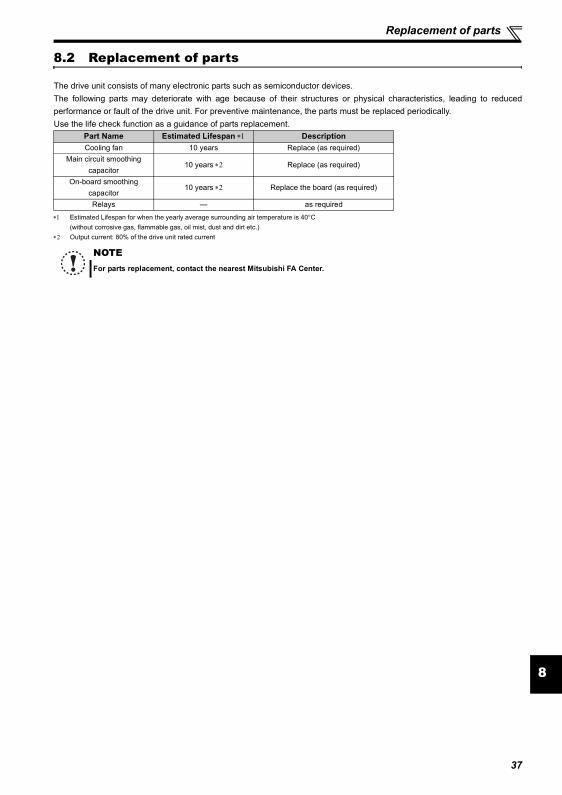
Replacement of parts
8
8.2 Replacement of parts
The drive unit consists of many electronic parts such as semiconductor devices.The following parts may deteriorate with age because of their structures or physical characteristics, leading to reducedperformance or fault of the drive unit. For preventive maintenance, the parts must be replaced periodically.Use the life check function as a guidance of parts replacement.
∗1 Estimated Lifespan for when the yearly average surrounding air temperature is 40°C(without corrosive gas, flammable gas, oil mist, dust and dirt etc.)
∗2 Output current: 80% of the drive unit rated current
Part Name Estimated Lifespan ∗1 DescriptionCooling fan 10 years Replace (as required)
Main circuit smoothing capacitor
10 years ∗2 Replace (as required)
On-board smoothing capacitor
10 years ∗2 Replace the board (as required)
Relays — as required
NOTEFor parts replacement, contact the nearest Mitsubishi FA Center.
37
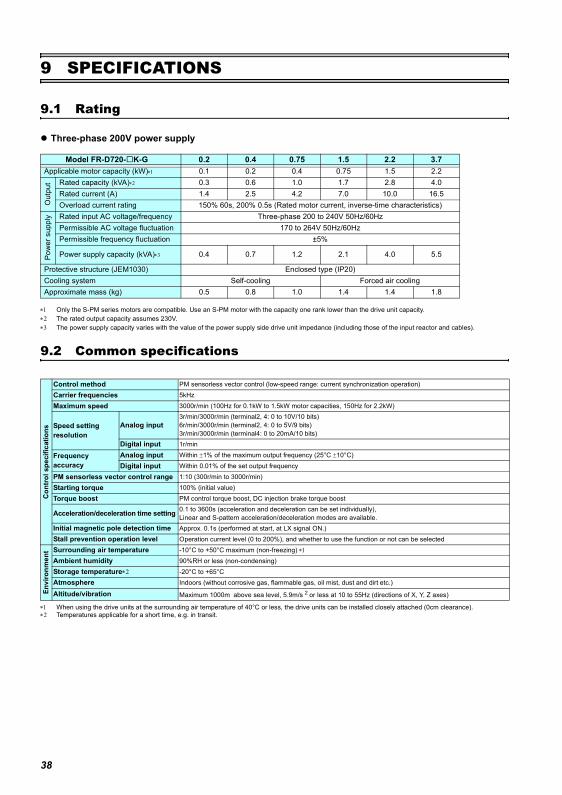
Rating
9 SPECIFICATIONS
9.1 Rating
Three-phase 200V power supply
∗1 Only the S-PM series motors are compatible. Use an S-PM motor with the capacity one rank lower than the drive unit capacity.∗2 The rated output capacity assumes 230V.∗3 The power supply capacity varies with the value of the power supply side drive unit impedance (including those of the input reactor and cables).
9.2 Common specifications
∗1 When using the drive units at the surrounding air temperature of 40°C or less, the drive units can be installed closely attached (0cm clearance).∗2 Temperatures applicable for a short time, e.g. in transit.
Model FR-D720- K-G 0.2 0.4 0.75 1.5 2.2 3.7Applicable motor capacity (kW)∗1 0.1 0.2 0.4 0.75 1.5 2.2
Out
put Rated capacity (kVA)∗2 0.3 0.6 1.0 1.7 2.8 4.0
Rated current (A) 1.4 2.5 4.2 7.0 10.0 16.5Overload current rating 150% 60s, 200% 0.5s (Rated motor current, inverse-time characteristics)
Pow
er s
uppl
y Rated input AC voltage/frequency Three-phase 200 to 240V 50Hz/60HzPermissible AC voltage fluctuation 170 to 264V 50Hz/60HzPermissible frequency fluctuation ±5%
Power supply capacity (kVA)∗3 0.4 0.7 1.2 2.1 4.0 5.5
Protective structure (JEM1030) Enclosed type (IP20)Cooling system Self-cooling Forced air coolingApproximate mass (kg) 0.5 0.8 1.0 1.4 1.4 1.8
Con
trol
spe
cific
atio
ns
Control method PM sensorless vector control (low-speed range: current synchronization operation)
Carrier frequencies 5kHz
Maximum speed 3000r/min (100Hz for 0.1kW to 1.5kW motor capacities, 150Hz for 2.2kW)
Speed setting resolution
Analog input3r/min/3000r/min (terminal2, 4: 0 to 10V/10 bits)6r/min/3000r/min (terminal2, 4: 0 to 5V/9 bits)3r/min/3000r/min (terminal4: 0 to 20mA/10 bits)
Digital input 1r/min
Frequency accuracy
Analog input Within ±1% of the maximum output frequency (25°C ±10°C)
Digital input Within 0.01% of the set output frequency
PM sensorless vector control range 1:10 (300r/min to 3000r/min)
Starting torque 100% (initial value)
Torque boost PM control torque boost, DC injection brake torque boost
Acceleration/deceleration time setting 0.1 to 3600s (acceleration and deceleration can be set individually), Linear and S-pattern acceleration/deceleration modes are available.
Initial magnetic pole detection time Approx. 0.1s (performed at start, at LX signal ON.)Stall prevention operation level Operation current level (0 to 200%), and whether to use the function or not can be selected
Envi
ronm
ent Surrounding air temperature -10°C to +50°C maximum (non-freezing) ∗1
Ambient humidity 90%RH or less (non-condensing)Storage temperature∗2 -20°C to +65°CAtmosphere Indoors (without corrosive gas, flammable gas, oil mist, dust and dirt etc.)
Altitude/vibration Maximum 1000m above sea level, 5.9m/s 2 or less at 10 to 55Hz (directions of X, Y, Z axes)
38
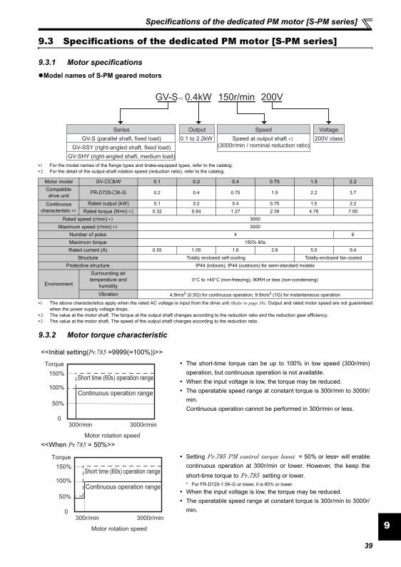
Specifications of the dedicated PM motor [S-PM series]
9
9.3 Specifications of the dedicated PM motor [S-PM series]
9.3.1 Motor specificationsModel names of S-PM geared motors
∗1 For the model names of the flange types and brake-equipped types, refer to the catalog.∗2 For the detail of the output-shaft rotation speed (reduction ratio), refer to the catalog.
∗1 The above characteristics apply when the rated AC voltage is input from the drive unit (Refer to page 38). Output and rated motor speed are not guaranteedwhen the power supply voltage drops.
∗2 The value at the motor shaft. The torque at the output shaft changes according to the reduction ratio and the reduction gear efficiency.∗3 The value at the motor shaft. The speed of the output shaft changes according to the reduction ratio.
9.3.2 Motor torque characteristic
Motor model GV- kW 0.1 0.2 0.4 0.75 1.5 2.2Compatibledrive unit FR-D720- K-G 0.2 0.4 0.75 1.5 2.2 3.7
Continuous characteristic ∗1
Rated output (kW) 0.1 0.2 0.4 0.75 1.5 2.2
Rated torque (N m) ∗2 0.32 0.64 1.27 2.39 4.78 7.00
Rated speed (r/min) ∗3 3000
Maximum speed (r/min) ∗3 3000
Number of poles 4 6
Maximum torque 150% 60s
Rated current (A) 0.55 1.05 1.6 2.8 5.5 9.4
Structure Totally enclosed self-cooling Totally-enclosed fan-cooled
Protective structure IP44 (indoors), IP44 (outdoors) for semi-standard models
Environment
Surrounding air temperature and
humidity0°C to +40°C (non-freezing), 90RH or less (non-condensing)
Vibration 4.9m/s2 (0.5G) for continuous operation, 9.8m/s2 (1G) for instantaneous operation
<<Initial setting(Pr.785 =9999(=100%))>>The short-time torque can be up to 100% in low speed (300r/min)operation, but continuous operation is not available. When the input voltage is low, the torque may be reduced. The operatable speed range at constant torque is 300r/min to 3000r/min. Continuous operation cannot be performed in 300r/min or less.
<<When Pr.785 = 50%>>
Setting Pr.785 PM control torque boost = 50% or less∗ will enablecontinuous operation at 300r/min or lower. However, the keep theshort-time torque to Pr.785 setting or lower. * For FR-D720-1.5K-G or lower, it is 80% or lower.
When the input voltage is low, the torque may be reduced. The operatable speed range at constant torque is 300r/min to 3000r/min.
GV-S 0.4kW 150r/min 200V
Series
GV-S (parallel shaft, fixed load)
GV-SSY (right-angled shaft, fixed load)
GV-SHY (right-angled shaft, medium load)
Output
0.1 to 2.2kW
Speed
Speed at output shaft ∗2
(3000r/min / nominal reduction ratio)
Voltage
200V class
∗1
150%
100%
50%
0
Torque
Continuous operation range
Short time (60s) operation range
300r/min 3000r/min
Motor rotation speed
150%
100%
50%
0
Torque
300r/min 3000r/min
Motor rotation speed
Continuous operation range
Short time (60s) operation range
39
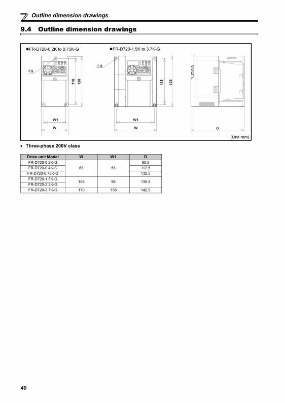
Outline dimension drawings
9.4 Outline dimension drawings
• Three-phase 200V class
(Unit:mm)
Drive unit Model W W1 DFR-D720-0.2K-G
68 5680.5
FR-D720-0.4K-G 112.5FR-D720-0.75K-G 132.5FR-D720-1.5K-G
108 96 135.5FR-D720-2.2K-GFR-D720-3.7K-G 170 158 142.5
W1W1
WW
11
8
128
D
5
11
8
128
5
FR-D720-0.2K to 0.75K-G FR-D720-1.5K to 3.7K-G
40
The EU Directives are issued to standardize different national regulations of the EU Member States and to facilitate freemovement of the equipment, whose safety is ensured, in the EU territory.Since 1996, compliance with the EMC Directive that is one of the EU Directives has been legally required. Since 1997,compliance with the Low Voltage Directive, another EU Directive, has been also legally required. When a manufacturerconfirms its equipment to be compliant with the EMC Directive and the Low Voltage Directive, the manufacturer must declarethe conformity and affix the CE marking.
The authorized representative in the EUThe authorized representative in the EU is shown below.Name: Mitsubishi Electric Europe B.V.Address: Gothaer Strasse 8, 40880 Ratingen, Germany
NoteWe declare that this drive unit, when equipped with the dedicated EMC filter, conforms with the EMC Directive in industrialenvironments and affix the CE marking on the drive unit. When using the drive unit in a residential area, take appropriate measures and ensure the conformity of the drive unit usedin the residential area.
(1) EMC Directive
We declare that this drive unit, when equipped with the EMC Directive compliant EMC filter, conforms with the EMCDirective and affix the CE marking on the drive unit (except the single-phase 100V power supply model).
EMC Directive: 2004/108/ECStandard(s): EN61800-3:2004 (Second environment / PDS Category "C3")
Note: First environmentEnvironment including residential buildings. Includes building directly connected without a transformer to the lowvoltage power supply network which supplies power to residential buildings.
Second environmentEnvironment including all buildings except buildings directly connected without a transformer to the lower voltagepower supply network which supplies power to residential buildings.
Note∗ Set the EMC Directive compliant EMC filter to the drive unit. Insert line noise filters and ferrite cores to the power and
control cables as required.∗ Connect the drive unit to an earthed power supply. ∗ Install a motor, the EMC Directive compliant EMC filter, and a control cable according to the instructions written in the
EMC Installation Guidelines (BCN-A21041-204). (Please contact your sales representative for the EMC InstallationGuidelines.)
∗ The cable length between the drive unit and the motor is 5m maximum. ∗ Confirm that the final integrated system with the drive unit conforms with the EMC Directive.
Appendix 1 Instructions for Compliance with the EU Directives
41
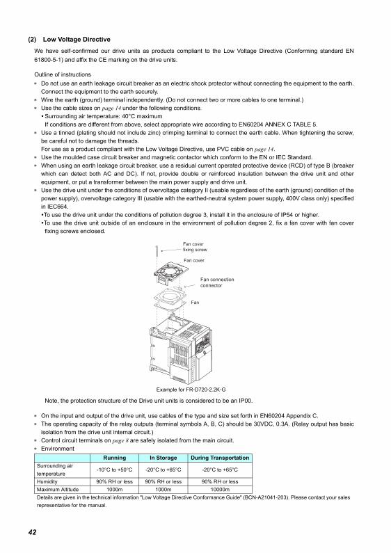
(2) Low Voltage DirectiveWe have self-confirmed our drive units as products compliant to the Low Voltage Directive (Conforming standard EN61800-5-1) and affix the CE marking on the drive units.
Outline of instructions∗ Do not use an earth leakage circuit breaker as an electric shock protector without connecting the equipment to the earth.
Connect the equipment to the earth securely.∗ Wire the earth (ground) terminal independently. (Do not connect two or more cables to one terminal.)∗ Use the cable sizes on page 14 under the following conditions.
Surrounding air temperature: 40°C maximumIf conditions are different from above, select appropriate wire according to EN60204 ANNEX C TABLE 5.
∗ Use a tinned (plating should not include zinc) crimping terminal to connect the earth cable. When tightening the screw,be careful not to damage the threads.For use as a product compliant with the Low Voltage Directive, use PVC cable on page 14.
∗ Use the moulded case circuit breaker and magnetic contactor which conform to the EN or IEC Standard.∗ When using an earth leakage circuit breaker, use a residual current operated protective device (RCD) of type B (breaker
which can detect both AC and DC). If not, provide double or reinforced insulation between the drive unit and otherequipment, or put a transformer between the main power supply and drive unit.
∗ Use the drive unit under the conditions of overvoltage category II (usable regardless of the earth (ground) condition of thepower supply), overvoltage category III (usable with the earthed-neutral system power supply, 400V class only) specifiedin IEC664.To use the drive unit under the conditions of pollution degree 3, install it in the enclosure of IP54 or higher.To use the drive unit outside of an enclosure in the environment of pollution degree 2, fix a fan cover with fan coverfixing screws enclosed.
Note, the protection structure of the Drive unit units is considered to be an IP00.
∗ On the input and output of the drive unit, use cables of the type and size set forth in EN60204 Appendix C.∗ The operating capacity of the relay outputs (terminal symbols A, B, C) should be 30VDC, 0.3A. (Relay output has basic
isolation from the drive unit internal circuit.)∗ Control circuit terminals on page 8 are safely isolated from the main circuit.∗ Environment
Example for FR-D720-2.2K-G
Running In Storage During TransportationSurrounding air temperature
-10°C to +50°C -20°C to +65°C -20°C to +65°C
Humidity 90% RH or less 90% RH or less 90% RH or lessMaximum Altitude 1000m 1000m 10000mDetails are given in the technical information "Low Voltage Directive Conformance Guide" (BCN-A21041-203). Please contact your sales representative for the manual.
Fan connection
connector
Fan
Fan cover
Fan cover
fixing screw
42
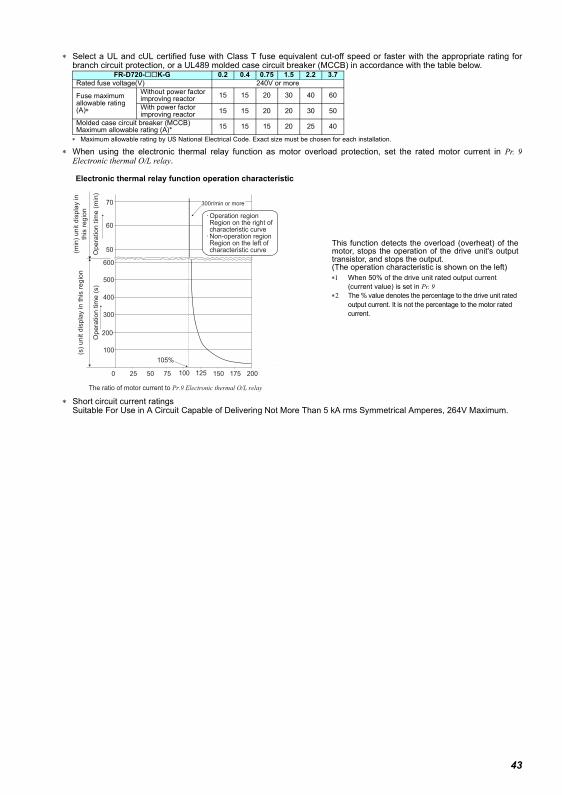
∗ Select a UL and cUL certified fuse with Class T fuse equivalent cut-off speed or faster with the appropriate rating forbranch circuit protection, or a UL489 molded case circuit breaker (MCCB) in accordance with the table below.
∗ Maximum allowable rating by US National Electrical Code. Exact size must be chosen for each installation.
∗ When using the electronic thermal relay function as motor overload protection, set the rated motor current in Pr. 9Electronic thermal O/L relay.
∗ Short circuit current ratingsSuitable For Use in A Circuit Capable of Delivering Not More Than 5 kA rms Symmetrical Amperes, 264V Maximum.
FR-D720- K-G 0.2 0.4 0.75 1.5 2.2 3.7Rated fuse voltage(V) 240V or more
Fuse maximum allowable rating (A)∗
Without power factor improving reactor 15 15 20 30 40 60
With power factor improving reactor 15 15 20 20 30 50
Molded case circuit breaker (MCCB)Maximum allowable rating (A)* 15 15 15 20 25 40
This function detects the overload (overheat) of themotor, stops the operation of the drive unit's outputtransistor, and stops the output. (The operation characteristic is shown on the left)∗1 When 50% of the drive unit rated output current
(current value) is set in Pr. 9 ∗2 The % value denotes the percentage to the drive unit rated
output current. It is not the percentage to the motor rated current.
200
105%
50 125100 150
100
200
300
600
50
60
70
25 75 175
400
500
(s)
unit d
ispla
y in this
regio
n(m
in)
unit d
ispla
y in
this
regio
n
Opera
tion tim
e (
min
)O
pera
tion tim
e (
s)
300r/min or more
Operation region Region on the right of characteristic curve Non-operation region Region on the left of characteristic curve
0
The ratio of motor current to Pr.9 Electronic thermal O/L relay
Electronic thermal relay function operation characteristic
43
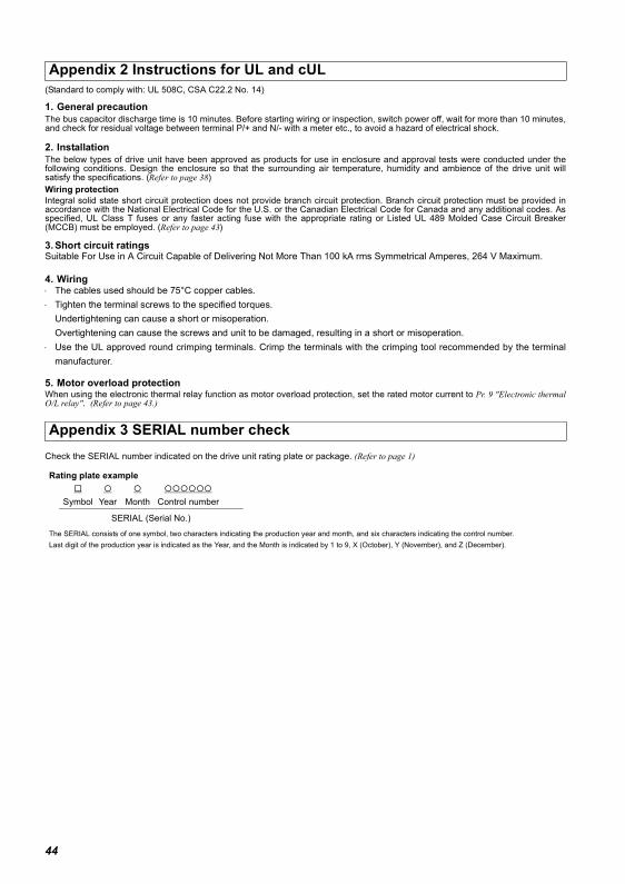
44
(Standard to comply with: UL 508C, CSA C22.2 No. 14)
1. General precautionThe bus capacitor discharge time is 10 minutes. Before starting wiring or inspection, switch power off, wait for more than 10 minutes,and check for residual voltage between terminal P/+ and N/- with a meter etc., to avoid a hazard of electrical shock.
2. InstallationThe below types of drive unit have been approved as products for use in enclosure and approval tests were conducted under thefollowing conditions. Design the enclosure so that the surrounding air temperature, humidity and ambience of the drive unit willsatisfy the specifications. (Refer to page 38)Wiring protectionIntegral solid state short circuit protection does not provide branch circuit protection. Branch circuit protection must be provided inaccordance with the National Electrical Code for the U.S. or the Canadian Electrical Code for Canada and any additional codes. Asspecified, UL Class T fuses or any faster acting fuse with the appropriate rating or Listed UL 489 Molded Case Circuit Breaker(MCCB) must be employed. (Refer to page 43)
3. Short circuit ratingsSuitable For Use in A Circuit Capable of Delivering Not More Than 100 kA rms Symmetrical Amperes, 264 V Maximum.
4. Wiring⋅ The cables used should be 75°C copper cables.⋅ Tighten the terminal screws to the specified torques.
Undertightening can cause a short or misoperation.Overtightening can cause the screws and unit to be damaged, resulting in a short or misoperation.
⋅ Use the UL approved round crimping terminals. Crimp the terminals with the crimping tool recommended by the terminalmanufacturer.
5. Motor overload protectionWhen using the electronic thermal relay function as motor overload protection, set the rated motor current to Pr. 9 "Electronic thermalO/L relay". (Refer to page 43.)
Check the SERIAL number indicated on the drive unit rating plate or package. (Refer to page 1)
Appendix 2 Instructions for UL and cUL
Appendix 3 SERIAL number check
Rating plate example
Symbol Year Month Control number
SERIAL (Serial No.)
The SERIAL consists of one symbol, two characters indicating the production year and month, and six characters indicating the control number.Last digit of the production year is indicated as the Year, and the Month is indicated by 1 to 9, X (October), Y (November), and Z (December).

45
MEMO
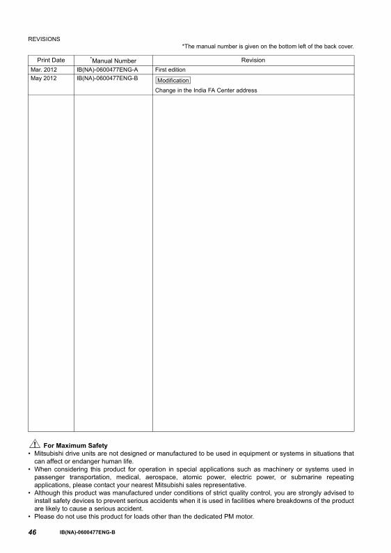
46
REVISIONS*The manual number is given on the bottom left of the back cover.
For Maximum Safety• Mitsubishi drive units are not designed or manufactured to be used in equipment or systems in situations that
can affect or endanger human life.• When considering this product for operation in special applications such as machinery or systems used in
passenger transportation, medical, aerospace, atomic power, electric power, or submarine repeatingapplications, please contact your nearest Mitsubishi sales representative.
• Although this product was manufactured under conditions of strict quality control, you are strongly advised toinstall safety devices to prevent serious accidents when it is used in facilities where breakdowns of the productare likely to cause a serious accident.
• Please do not use this product for loads other than the dedicated PM motor.
Print Date *Manual Number RevisionMar. 2012 IB(NA)-0600477ENG-A First editionMay 2012 IB(NA)-0600477ENG-B
Change in the India FA Center address
Modification
IB(NA)-0600477ENG-B
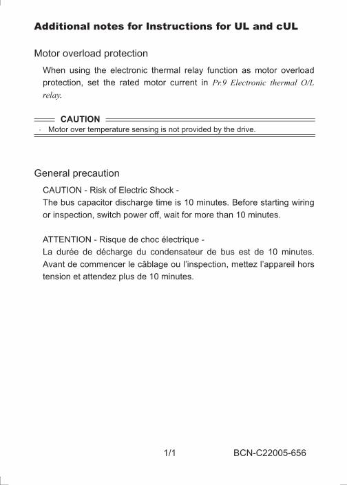
1/1 BCN-C22005-656
Additional notes for Instructions for UL and cUL
Motor overload protectionWhen using the electronic thermal relay function as motor overloadprotection, set the rated motor current in Pr.9 Electronic thermal O/Lrelay.
General precautionCAUTION - Risk of Electric Shock -The bus capacitor discharge time is 10 minutes. Before starting wiringor inspection, switch power off, wait for more than 10 minutes.
ATTENTION - Risque de choc électrique -La durée de décharge du condensateur de bus est de 10 minutes.Avant de commencer le câblage ou l’inspection, mettez l’appareil horstension et attendez plus de 10 minutes.
CAUTION Motor over temperature sensing is not provided by the drive.
BCN-C22005-656.fm 1 ページ 2013年8月29日 木曜日 午後1時16分

1/1 BCN-C22005-695
Instructions for UL and cUL
Wiring protection
Integral solid state short circuit protection does not provide branch cir-
cuit protection. Branch circuit protection must be provided in accor-
dance with the National Electrical Code for the U.S. or the Canadian
Electrical Code for Canada and any additional codes. As specified, UL
Class T ,Class J,Class CC fuses or any faster acting fuse with the
appropriate rating or Listed UL 489 Molded Case Circuit Breaker
(MCCB) must be employed.
bcnc22005695.fm 1 ページ 2014年10月1日 水曜日 午前11時24分

International FA Center
Korean FA Center
Beijing FA Center
German FA Center
UK FA Center
Czech Republic FA Center
Tianjin FA Center
Shanghai FA Center
Guangzhou FA CenterTaiwan FA Center
North American FA Center
ASEAN FA Center
Thailand FA Center
India FA Center
Brazil FA Center
Russian FA CenterEuropean FA Center
Shanghai FA CenterMITSUBISHI ELECTRIC AUTOMATION (CHINA) LTD. Shanghai FA Center3F, Mitsubishi Electric Automation Center, No.1386 Hongqiao Road, Changning District, Shanghai, ChinaTEL. 86-21-2322-3030 FAX. 86-21-2322-3000
Beijing FA CenterMITSUBISHI ELECTRIC AUTOMATION (CHINA) LTD. Beijing FA Center9F, Office Tower 1, Henderson Centre, 18 Jianguomennei Avenue, Dongcheng District, Beijing, ChinaTEL. 86-10-6518-8830 FAX. 86-10-6518-3907
Tianjin FA CenterMITSUBISHI ELECTRIC AUTOMATION (CHINA) LTD. Tianjin FA CenterUnit 2003-2004B, Tianjin City Tower, No.35, You Yi Road, He Xi District, Tianjin, ChinaTEL 86-22-2813-1015 FAX. 86-22-2813-1017
Guangzhou FA CenterMITSUBISHI ELECTRIC AUTOMATION (CHINA) LTD. Guangzhou FA CenterRoom.1609, North Tower, The Hub Center, No.1068, Xin Gang East Road, Haizhu District, Guangzhou,ChinaTEL. 86-20-8923-6730 FAX. 86-20-8923-6715
Korean FA CenterMITSUBISHI ELECTRIC AUTOMATION KOREA CO., LTD. (Service)B1F,2F, 1480-6, Gayang-Dong, Gangseo-Gu, Seoul, 157-200, KoreaTEL. 82-2-3660-9630 FAX. 82-2-3663-0475
Taiwan FA CenterSETSUYO ENTERPRISE CO., LTD.3F., No.105, Wugong 3 rd, Wugu Dist, New Taipei City 24889, Taiwan, R.O.C.TEL. 886-2-2299-9917 FAX. 886-2-2299-9963
ASEAN FA CenterMITSUBISHI ELECTRIC ASIA PTE, LTD. ASEAN Factory Automation Centre307 Alexandra Road #05-01/02, Mitsubishi Electric Building, SingaporeTEL. 65-6470-2480 FAX. 65-6476-7439
India FA CenterMITSUBISHI ELECTRIC INDIA PVT. LTD. India Factory Automation Centre2nd Floor, Tower A & B, Cyber Greens, DLF Cyber City, DLF Phase-III, Gurgaon- 122002 Haryana, IndiaTEL. 91-124-4630300 FAX. 91-124-4630399
Thailand FA CenterMITSUBISHI ELECTRIC AUTOMATION (THAILAND) CO., LTD.Bang-Chan Industrial Estate No.111, Soi Serithai 54, T.Kannayao, A.Kannayao, Bangkok 10230 ThailandTEL. 66-2906-3238 FAX. 66-2906-3239
North American FA CenterMITSUBISHI ELECTRIC AUTOMATION, INC.500 Corporate Woods Parkway, Vernon Hills, IL 60061 U.S.ATEL. 1-847-478-2334 FAX. 1-847-478-2253
Brazil FA CenterMELCO-TEC Representacao Comercial e Assessoria Tecnica Ltda.Av. Paulista, 1439, cj74, Bela Vista, Sao Paulo CEP: 01311-200 - SP BrazilTEL. 55-11-3146-2200 FAX. 55-11-3146-2217
European FA CenterMITSUBISHI ELECTRIC EUROPE B.V. Polish BranchKrakowska 50, 32-083 Balice, PolandTEL. 48-12-630-4700 FAX. 48-12-630-4701
German FA CenterMITSUBISHI ELECTRIC EUROPE B.V. - German BranchGothaer Strasse 8, D-40880 Ratingen, GermanyTEL. 49-2102-486-0 FAX. 49-2102-486-1120
UK FA CenterMITSUBISHI ELECTRIC EUROPE B. V. UK BranchTravellers Lane, Hatfield, Hertfordshire, AL10 8XB, U.K.TEL. 44-1707-27-6100 FAX. 44-1707-27-8695
Czech Republic FA CenterMITSUBISHI ELECTRIC EUROPE B.V. -o.s. Czech officeAvenir Business Park, Radlicka 714/113a,158 00 Praha 5, Czech RepublicTEL. 420-251-551-470 FAX. 420-251-551-471
Russian FA CenterMITSUBISHI ELECTRIC EUROPE B.V. Russian BranchSt.Petersburg officePiskarevsky pr. 2, bld 2, lit "Sch", BC "Benua", office 720; 195027, St. Petersburg, RussiaTEL. 7-812-633-3497 FAX. 7-812-633-3499

HEAD OFFICE: TOKYO BUILDING 2-7-3, MARUNOUCHI, CHIYODA-KU, TOKYO 100-8310, JAPAN
IB(NA)-0600477ENG-B(1205)MEE Printed in Japan Specifications subject to change without notice.


![LED Keypads D720 Series User’s Guide › public › ...Note: The [A], [B], and [C] keys can perform various functions. These functions require a few seconds before they are completed,](https://img.dokumen.tips/doc/110x75/5f1025657e708231d447acc7/led-keypads-d720-series-useras-guide-a-public-a-note-the-a-b-and.jpg)