Embed Size (px)
Citation preview
Page 1
Copyright © 2017 Avnet, Inc. AVNET, “Reach Further,” and the AV logo are registered trademarks of Avnet, Inc. All other brands are the property of their respective owners.
LIT# 5169-PicoZed-FMC-CC-GettingStarted-V1
PicoZed™ FPGA Mezzanine Connector (FMC) Carrier Card Getting Started Guide Version 2.1
Page 2
Document Control
Document Version: 2.1
Document Date: 10/05/2015
Document Author(s): Avnet
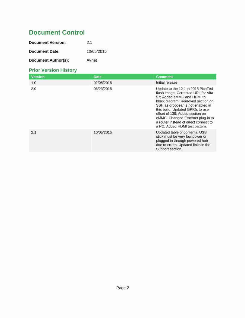
Prior Version History
Version Date Comment
1.0 02/08/2015 Initial release
2.0 06/23/2015 Update to the 12 Jun 2015 PicoZed flash image; Corrected URL for Vita 57; Added eMMC and HDMI to block diagram; Removed section on SSH as dropbear is not enabled in this build; Updated GPIOs to use offset of 138; Added section on
eMMC; Changed Ethernet plug‐in to a router instead of direct connect to a PC; Added HDMI test pattern.
2.1 10/05/2015 Updated table of contents. USB stick must be very low power or plugged in through powered hub due to errata. Updated links in the Support section.

Page 3
Contents
1 Getting Started with the PicoZed FMC Carrier Card ............................................. 4
2 What’s Inside the Box? ......................................................................................... 5
2.1 PicoZed PZCC-FMC Kit contents ......................................................................................... 5
3 What’s on the Web?.............................................................................................. 6
3.1 Official Documentation ......................................................................................................... 6
3.2 Tutorials and Reference Designs ......................................................................................... 6
3.3 Trainings and Videos ........................................................................................................... 6
4 PicoZed PZCC-FMC Key Features ....................................................................... 7
5 PicoZed PZCC-FMC Basic Setup and Operation ................................................. 9
5.1 Mounting the PicoZed ........................................................................................................ 11
5.2 Example Design ................................................................................................................ 12
5.3 Hardware Setup ................................................................................................................ 13
6 Running the Example.......................................................................................... 16
7 Login ................................................................................................................... 19
8 File System ......................................................................................................... 19
9 Interact with GPIO (LED and push button) .......................................................... 23
10 Ethernet Operations ........................................................................................... 32
10.1 Ping ................................................................................................................................... 32
10.2 Web Server ....................................................................................................................... 32
10.3 FTP ................................................................................................................................... 32
11 Mass Storage: USB‐Host, microSD Card, eMMC ............................................... 34
11.1 eMMC ............................................................................................................................... 34
11.2 USB Memory Stick ............................................................................................................ 35
11.3 SD Card ............................................................................................................................ 37
12 HDMI................................................................................................................... 38
13 Poweroff .............................................................................................................. 39
14 Getting Help and Support ................................................................................... 40
14.1 Avnet Support.................................................................................................................... 40
14.2 Xilinx Support .................................................................................................................... 42
15 Appendix A: Format the microSD Card ............................................................... 43
16 Appendix B: Installing and Licensing Xilinx Software .......................................... 46
16.1 Install Vivado Design Suite, WebPack Edition .................................................................... 46

Page 4
1 Getting Started with the PicoZed FMC Carrier Card The Avnet PicoZed FMC Carrier Card (PZCC‐FMC) enables hardware and software developers to explore
the capabilities of the PicoZed System‐on‐Module (SOM). Coupled together, the PicoZed SOM and PZCC‐FMC allow designers to create or evaluate Zynq™‐ 7000 All Programmable SoC designs for both the
Processor Subsystem (PS) and the Programmable Logic (PL) fabric.
The PZCC‐FMC powers the PicoZed and connects the peripheral PHYs to I/O connectors. The PZCC‐FMC
exposes the PL I/Os, while also providing system, I/O, and transceiver power through the mezzanine MicroHeaders. The PicoZed PL I/Os are connected on the PZCC‐FMC to a Low‐Pin‐Count (LPC) FPGA Mezzanine Connector (FMC) based on the Vita 57 standard. A 2nd Ethernet circuit, 1080p HDMI, PCIe,
SFP+, Digilent Pmod™ Compatible headers, LEDs, and push‐buttons are additional features on the board.
Figure 1 – PicoZed FMC Carrier Card Board shown with PicoZed SOM Mounted
This Getting Started Guide will outline the steps to setup the PicoZed SOM and PZCC‐ FMC hardware. It
documents the procedure to run a PetaLinux design running on the ARM® dual‐core Cortex™‐A9
MPCore™ Processing System (PS).

Page 5
2 What’s Inside the Box? 2.1 PicoZed PZCC-FMC Kit contents
– PicoZed FMC Carrier Card (PZCC-FMC)
– 12V @ 5A AC/DC adapter
– power adapter plugs for international use
– microUSB cable
– USB Adapter: Male Micro-B to Female Standard-A
– microSD Card 4GB
– Generic PCIe bracket with screws (not shown)
– PicoZed mounting hardware – 4 stand-offs and 8 screws (not shown)
– Documentation (not shown)
– Quick Start Instruction card
– Welcome Letter

Page 6
3 What’s on the Web? PicoZed is a community-oriented kit, with all materials being made available through the PicoZed.org community website.
3.1 Official Documentation – Getting started guide
– Hardware user guide
– Schematics
– Errata
– Bill of materials
– Layout
– PCB net lengths
– Mechanical drawing
– 3D Model
– Board definition files for Vivado integration
– Programmable logic (PL) master user constraints
3.2 Tutorials and Reference Designs – Introduction to Zynq Design Tutorials
– PetaLinux BSP
– Booting PicoZed using QSPI and eMMC
– Transceiver IBERT tutorial
– PCIe tutorial
– Community projects
3.3 Trainings and Videos – Introduction to Zynq Software Design
– Introduction to Zynq Hardware Design

Page 7
4 PicoZed PZCC-FMC Key Features – Expansion connectors
– Low pin count (LPC) FMC with 72 PL I/Os (36 differential pairs)
– Three Digilent Pmod™ compatible interfaces
– Access to 24 user I/O
– One (8 I/O) connected to PS MIO (shared with eMMC on SOM)
– One (8 I/O) connected to Bank 13 (supported with 7Z015, 20, and 30 PicoZed only)
– One (8 I/O) connected to Bank 13 (supported with 7Z015 and 30 PicoZed only)
– Configuration and Debug
– Xilinx Platform Cable JTAG connector for SOM
– Xilinx Platform Cable JTAG connector for FMC
– General Purpose I/O
– 2 user LEDs
– 3 push buttons
– Memory
– bootable microSD card slot with 4GB microSD card
– Communications
– x1 PCIe Gen 2
– SFP+ cage
– SMA port for GTX/GTP
– 10/100/1000 Ethernet connector
– 10/100/1000 Ethernet PHY and connector
– USB 2.0 connector
– USB UART
– Other
– HDMI output port
– SMA reference clock input
– Adjustable bank voltage power supply

Page 8
Figure 2 – PicoZed Block Diagram
Figure 3 – PZCC-FMC Block Diagram

Page 9
5 PicoZed PZCC-FMC Basic Setup and Operation The PZCC‐FMC and PicoZed module only operate together. Neither will function stand‐ alone. The
functionality of both the PicoZed and the PZCC‐FMC is determined by the application booted from the
selected non‐volatile memory – whether that be the QSPI and eMMC on the PicoZed or the microSD card
on the PZCC‐FMC. Since the SD Card shipped with the PZCC‐FMC is not programmed prior to shipment,
the PZCC‐FMC does not ship with any pre‐configured design. However, the PicoZed modules are tested
in manufacturing with a PZCC‐FMC, so the default image stored in the PicoZed QSPI is fully compatible
with the PZCC‐FMC.
Of course, the primary purpose of the PZCC‐FMC is to allow both a PicoZed and an FMC module to be connected together. In this case, the application is still controlled by the PicoZed while the FMC may add enhanced functionality with additional circuitry.
This Getting Started Guide offers system developers examples of how to do several things with the PicoZed and PZCC‐FMC together:
1. Interact with GPIO (push button)
2. Use Ethernet for webserver and file transfer
3. Mount and use a USB memory stick
4. Mount and use the microSD card
In addition to the items included in the kit, you will also need the following to complete the exercises in this tutorial.
– PicoZed module
– Ethernet cable
– microSD card reader/adapter
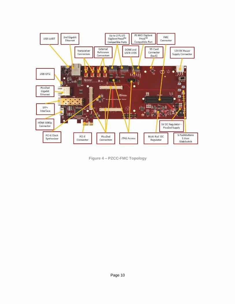
An image of the PicoZed PZCC‐FMC in its expected out‐of‐box configuration is shown below along with the
locations of several key components.
Page 10
Figure 4 – PZCC-FMC Topology
Page 11
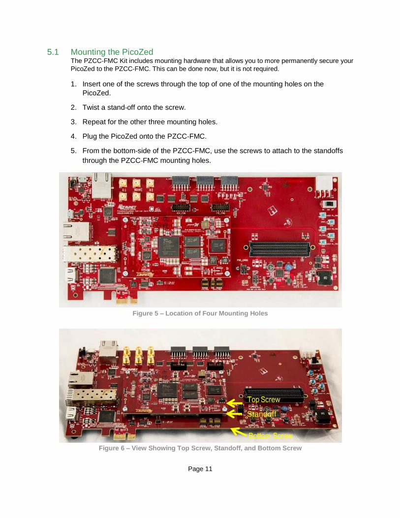
5.1 Mounting the PicoZed The PZCC‐FMC Kit includes mounting hardware that allows you to more permanently secure your
PicoZed to the PZCC‐FMC. This can be done now, but it is not required.
1. Insert one of the screws through the top of one of the mounting holes on the
PicoZed.
2. Twist a stand‐off onto the screw.
3. Repeat for the other three mounting holes.
4. Plug the PicoZed onto the PZCC‐FMC.
5. From the bottom‐side of the PZCC‐FMC, use the screws to attach to the standoffs
through the PZCC‐FMC mounting holes.
Figure 5 – Location of Four Mounting Holes
Figure 6 – View Showing Top Screw, Standoff, and Bottom Screw
Standoff
Page 12
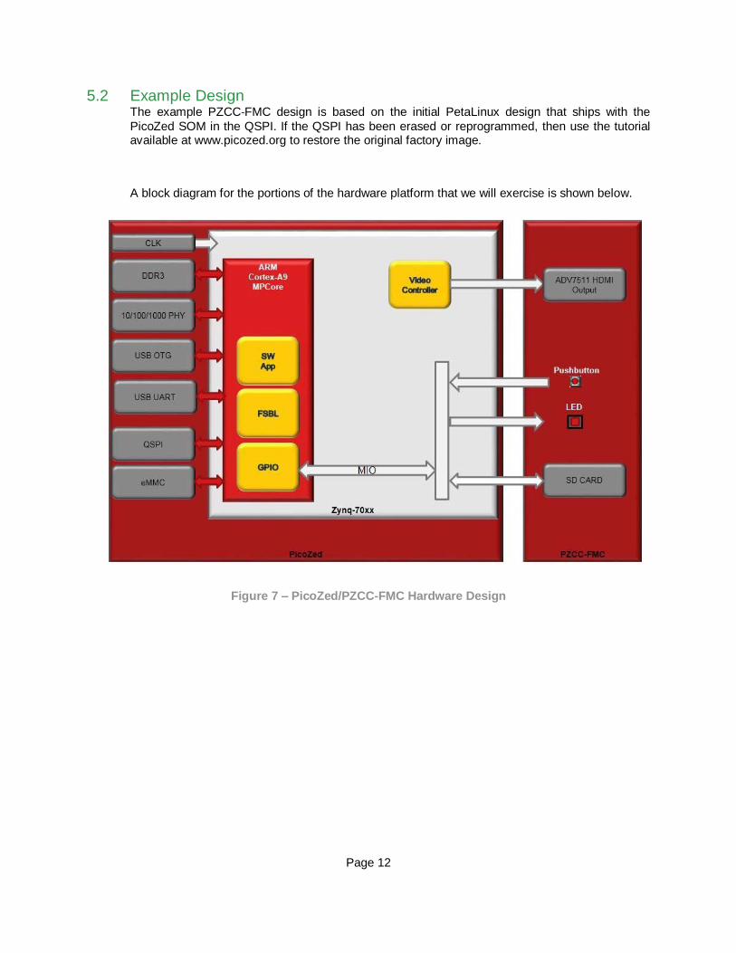
5.2 Example Design The example PZCC‐FMC design is based on the initial PetaLinux design that ships with the
PicoZed SOM in the QSPI. If the QSPI has been erased or reprogrammed, then use the tutorial available at www.picozed.org to restore the original factory image.
A block diagram for the portions of the hardware platform that we will exercise is shown below.
Figure 7 – PicoZed/PZCC-FMC Hardware Design
Page 13
5.3 Hardware Setup 1. The included microSD card must be formatted as FAT32. If this has not been
previously done, please do that now. Refer to Appendix A: Format the microSD Card
for specific instructions.
2. The PicoZed Ethernet expects to be connected to a device that can assign an IP
address, such as a router. The instructions in this Getting Started Guide assume the
Ethernet is plugged into a router on the same domain as the host PC.
3. A terminal program is required. Windows 7 or 8 does not come pre‐installed with a
terminal program. Tera Term was used in this example which can be downloaded
from the Tera Term project on the SourceForge Japan page: ttssh2.sourceforge.jp
Install Tera Term or another terminal program of your choice.
4. If not previously installed, go to www.PicoZed.org to download instructions for
installing the Silicon Labs CP2104 USB‐to‐UART driver.
http://picozed.org/support/documentation/4701
Silicon Labs CP210x USB‐to‐UART Setup Guide
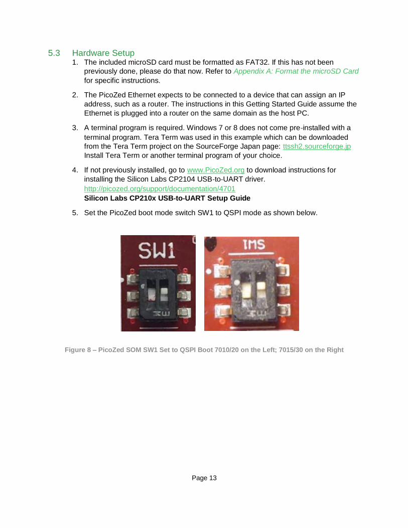
5. Set the PicoZed boot mode switch SW1 to QSPI mode as shown below.
Figure 8 – PicoZed SOM SW1 Set to QSPI Boot 7010/20 on the Left; 7015/30 on the Right

Page 14
Figure 9 – PicoZed 7010/20 SW1 Location
Figure 10 – PicoZed 7015/30 SW1 Location
6. Make sure the PZCC‐FMC power switch (SW7) is in the OFF position.
7. Insert the PicoZed module onto the PZCC‐FMC.

Page 15
8. Insert the blank formatted 4GB microSD card included with PZCC‐FMC into the microSD
card slot (J2) located on the underside of PZCC‐FMC (see Figure 4 for location).
9. Set the on-board jumpers as follows
– JP1 is open
– JP3 is closed in position 1-2
– JP4 is closed
– JP6 is open
– J9 is closed in positions 3-5 and 4-6
– CON2 is open, which sets V_ADJ to 1.8V
10. Insert the appropriate country plug into the 12V AC/DC adapter. Plug it into the J14 2x3
power connector. (NOTE – this 2x3 connector is NOT compatible with ATX power supplies.)
Page 16
6 Running the Example 11. Turn the power switch (SW7) on the PZCC‐FMC to the ON position.
12. Plug in the micro‐USB cable between the host PC and the PZCC‐FMC USB‐UART port (J6).
(The reason for waiting until AFTER power is applied to the board is explained in the PZCC‐
FMC Errata.)
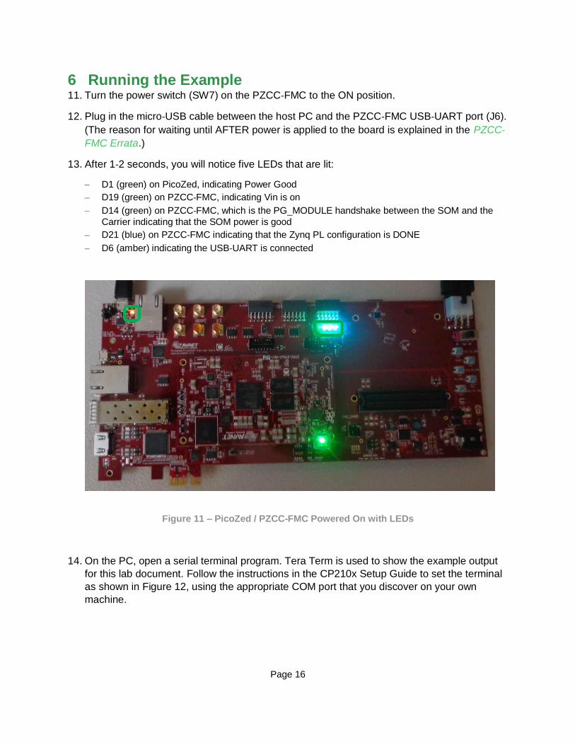
13. After 1‐2 seconds, you will notice five LEDs that are lit:
– D1 (green) on PicoZed, indicating Power Good
– D19 (green) on PZCC‐FMC, indicating Vin is on
– D14 (green) on PZCC‐FMC, which is the PG_MODULE handshake between the SOM and the
Carrier indicating that the SOM power is good
– D21 (blue) on PZCC‐FMC indicating that the Zynq PL configuration is DONE
– D6 (amber) indicating the USB‐UART is connected
Figure 11 – PicoZed / PZCC-FMC Powered On with LEDs
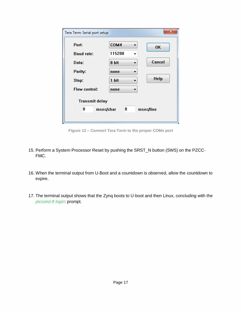
14. On the PC, open a serial terminal program. Tera Term is used to show the example output
for this lab document. Follow the instructions in the CP210x Setup Guide to set the terminal
as shown in Figure 12, using the appropriate COM port that you discover on your own
machine.
Page 17
Figure 12 – Connect Tera Term to the proper COMx port
15. Perform a System Processor Reset by pushing the SRST_N button (SW5) on the PZCC‐
FMC.
16. When the terminal output from U‐Boot and a countdown is observed, allow the countdown to
expire.
17. The terminal output shows that the Zynq boots to U‐boot and then Linux, concluding with the
picozed‐ft login: prompt.

Page 18
Figure 13 – PicoZed and PZCC-FMC Example Design
Page 19
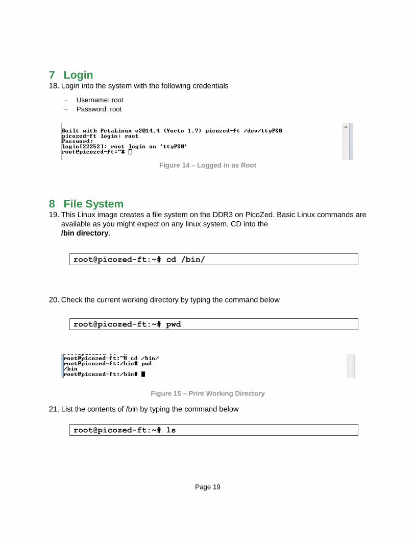
7 Login 18. Login into the system with the following credentials
– Username: root
– Password: root
Figure 14 – Logged in as Root
8 File System 19. This Linux image creates a file system on the DDR3 on PicoZed. Basic Linux commands are
available as you might expect on any linux system. CD into the
/bin directory.
20. Check the current working directory by typing the command below
Figure 15 – Print Working Directory
21. List the contents of /bin by typing the command below
root@picozed-ft:~# cd /bin/
root@picozed-ft:~# pwd
root@picozed-ft:~# ls

Page 20
Figure 16 – List Contents
22. To see full details, use the command below
root@picozed-ft:~# ls -l
Page 21
Figure 17 – Detailed List Contents
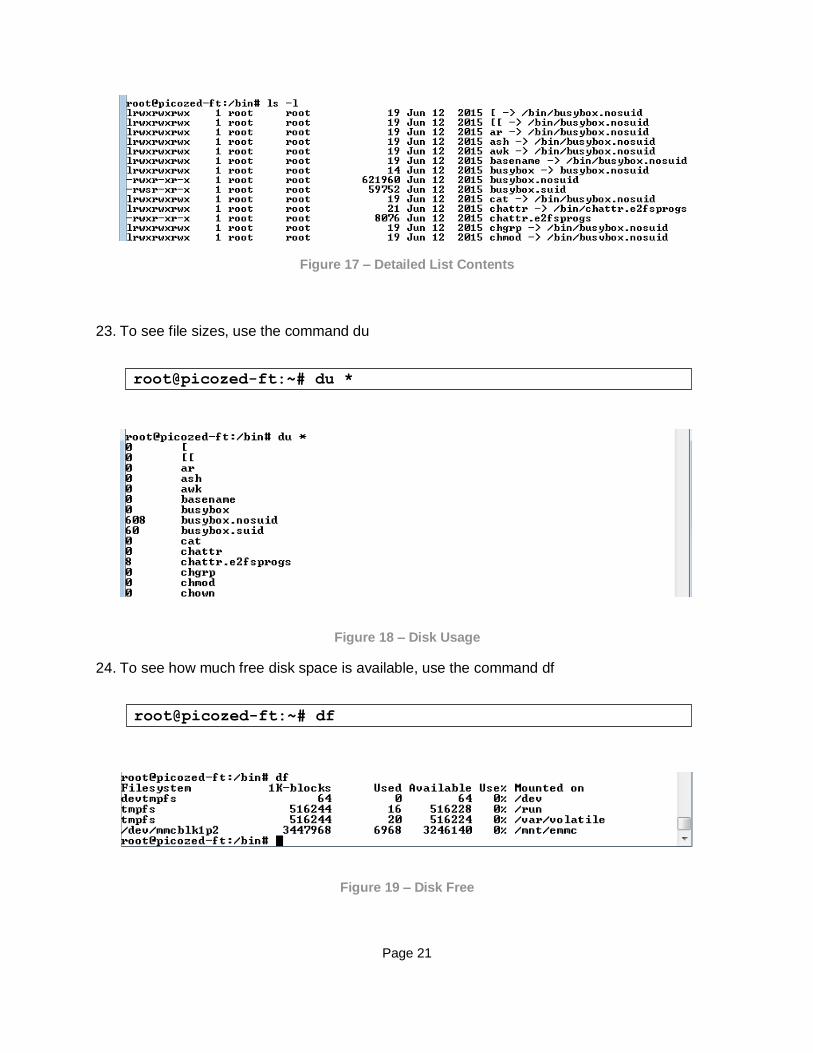
23. To see file sizes, use the command du
Figure 18 – Disk Usage
24. To see how much free disk space is available, use the command df
Figure 19 – Disk Free
root@picozed-ft:~# du *
root@picozed-ft:~# df

Page 22
25. To find a file in the file system, use the command ‘find’. The command below searches from
the root directory looking for a file called “flaschcp”.
Figure 20 – Find a File
26. In the case with two executables with the same name, it might be useful to know which one
is found without explicitly spelling out the path. Command ‘which’ will tell you the path of the
executable to be run. Cd to the root directory then test if iperf is in the path.
Figure 21 – Which
A short list of several more useful file- and directory-oriented commands include:
– mkdir
– rmdir
– rm
– chmod
– cp
– mv
– less <file>
root@picozed-ft:~# find / -name "flashcp"
root@picozed-ft:~# cd /
root@picozed-ft:~# which flashcp

Page 23
9 Interact with GPIO (LED and push button) With PicoZed booted to the Linux command prompt, the MIO GPIO hardware can be accessed directly via the generic sysfs GPIO driver.
27. From the Linux command prompt, take a look at the GPIO driver class within /sys
subfolders.
Notice how the GPIO driver exports controls via sysfs. Here we see that GPIOs are available for export via the export property.
Figure 22 – Exploring the Sysfs Subsystem
28. Take a look at Sheets 7 of the PZCC‐FMC schematic and determine which IO pin the LED
tied to MIO (PS_LED1 – D1) is connected to.
Figure 23 – PZCC-FMC Schematic Snippets Relating to PS_LED1 (D1)
root@picozed-ft:~# ls /sys/class/gpio/
Page 24
29. In looking at the schematic, you should have determined that the MIO LED D1 is connected
to pin JX3.pin40.
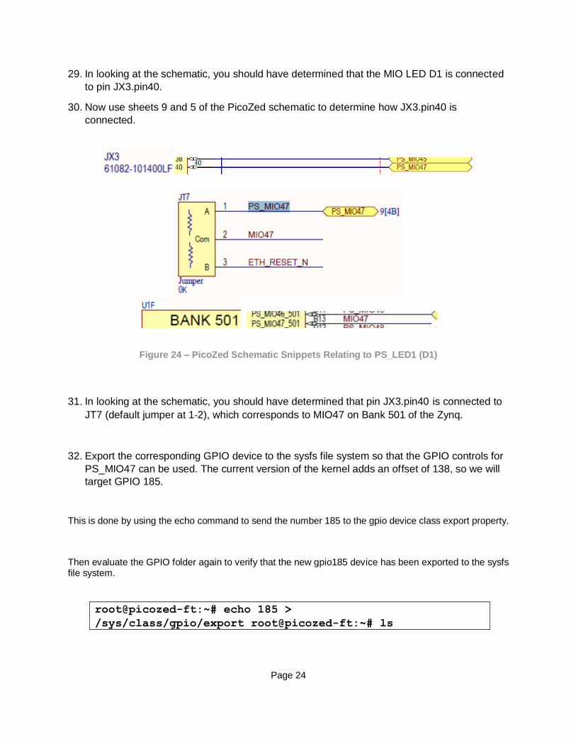
30. Now use sheets 9 and 5 of the PicoZed schematic to determine how JX3.pin40 is
connected.
Figure 24 – PicoZed Schematic Snippets Relating to PS_LED1 (D1)
31. In looking at the schematic, you should have determined that pin JX3.pin40 is connected to
JT7 (default jumper at 1‐2), which corresponds to MIO47 on Bank 501 of the Zynq.
32. Export the corresponding GPIO device to the sysfs file system so that the GPIO controls for
PS_MIO47 can be used. The current version of the kernel adds an offset of 138, so we will
target GPIO 185.
This is done by using the echo command to send the number 185 to the gpio device class export property.
Then evaluate the GPIO folder again to verify that the new gpio185 device has been exported to the sysfs file system.
root@picozed-ft:~# echo 185 >
/sys/class/gpio/export root@picozed-ft:~# ls
/sys/class/gpio/

Page 25
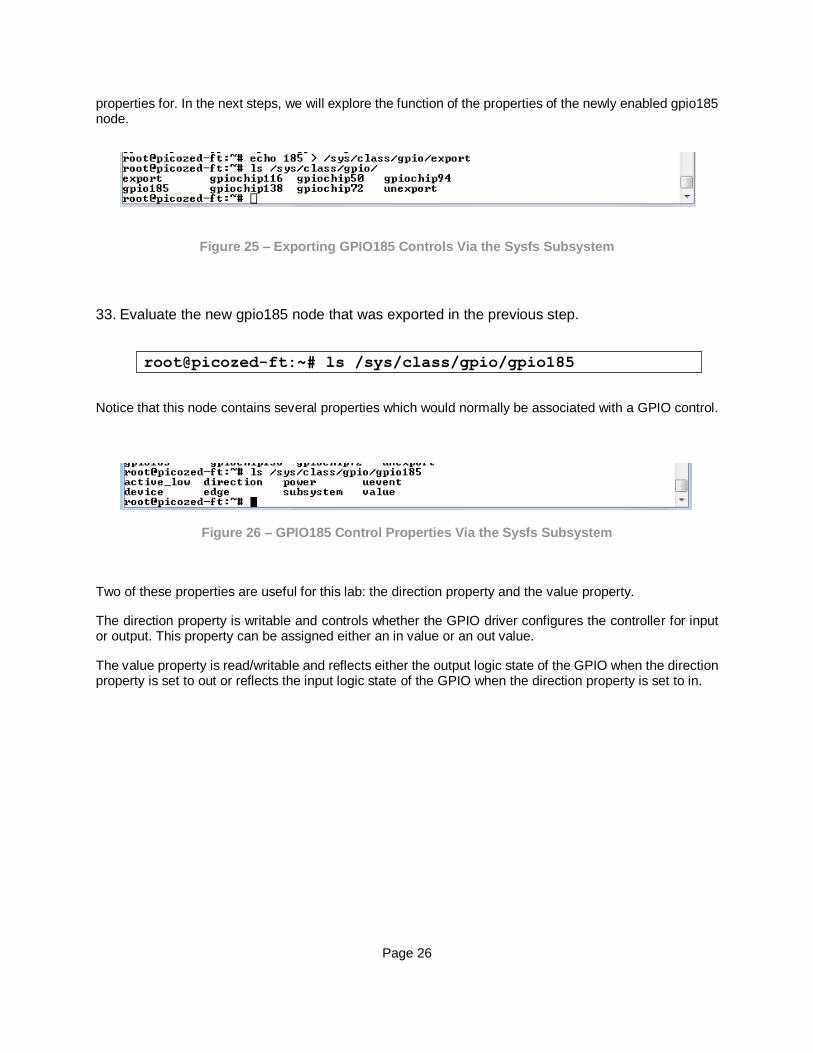
Notice that the export property has caused the gpio185 node to become available. Behind the scenes, the GPIO driver received a write call and used the 185 parameter entry to determine which GPIO channel to enable and export control
Page 26
properties for. In the next steps, we will explore the function of the properties of the newly enabled gpio185 node.
Figure 25 – Exporting GPIO185 Controls Via the Sysfs Subsystem
33. Evaluate the new gpio185 node that was exported in the previous step.
Notice that this node contains several properties which would normally be associated with a GPIO control.
Figure 26 – GPIO185 Control Properties Via the Sysfs Subsystem
Two of these properties are useful for this lab: the direction property and the value property.
The direction property is writable and controls whether the GPIO driver configures the controller for input or output. This property can be assigned either an in value or an out value.
The value property is read/writable and reflects either the output logic state of the GPIO when the direction property is set to out or reflects the input logic state of the GPIO when the direction property is set to in.
root@picozed-ft:~# ls /sys/class/gpio/gpio185
Page 27
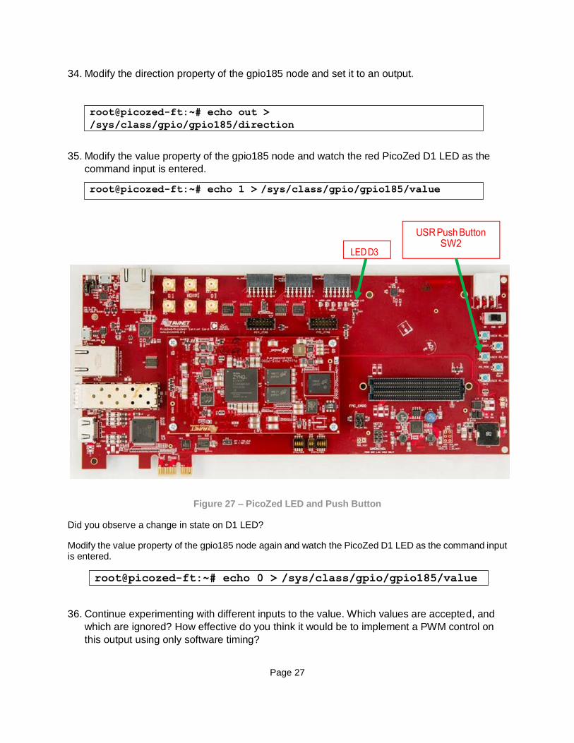
34. Modify the direction property of the gpio185 node and set it to an output.
35. Modify the value property of the gpio185 node and watch the red PicoZed D1 LED as the
command input is entered.
Figure 27 – PicoZed LED and Push Button
Did you observe a change in state on D1 LED?
Modify the value property of the gpio185 node again and watch the PicoZed D1 LED as the command input is entered.
36. Continue experimenting with different inputs to the value. Which values are accepted, and
which are ignored? How effective do you think it would be to implement a PWM control on
this output using only software timing?
root@picozed-ft:~# echo out >
/sys/class/gpio/gpio185/direction
root@picozed-ft:~# echo 1 > /sys/class/gpio/gpio185/value
root@picozed-ft:~# echo 0 > /sys/class/gpio/gpio185/value
Page 28
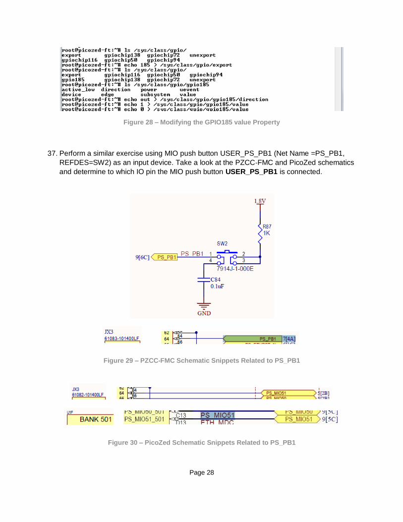
Figure 28 – Modifying the GPIO185 value Property
37. Perform a similar exercise using MIO push button USER_PS_PB1 (Net Name =PS_PB1,
REFDES=SW2) as an input device. Take a look at the PZCC‐FMC and PicoZed schematics
and determine to which IO pin the MIO push button USER_PS_PB1 is connected.
Figure 29 – PZCC-FMC Schematic Snippets Related to PS_PB1
Figure 30 – PicoZed Schematic Snippets Related to PS_PB1

Page 29
38. In looking at the schematics, you should have determined that the MIO push button PS_PB1
is connected to signal PS_MIO51. Using this MIO number, export the corresponding GPIO
device (don’t forget the 138 offset) for use and evaluate the GPIO folder again.
39. Modify the direction property of the gpio189 node and set it to input.
40. Read the value property of the gpio189 node.
41. Using the up arrow key on the keyboard to repeat a command in the command line history,
repeat the above command while pressing the MIO push button. Did you observe a change
in state of the value property read from the push button?
42. Continue experimenting with reading the different input states from the value properties.
How effective do you think it would be to poll the push buttons for changes in state?
Figure 31 – Reading the GPIO189 value Property
43. Think how you might use the button to control the LED. When the button is pushed, it
produces a ‘1’ and when not pushed a ‘0’. Lighting the LED requires that you send it a ‘1’
and to turn it off a ‘0’.
root@picozed-ft:~# echo 189 > /sys/class/gpio/export
root@picozed-ft:~# echo in >
/sys/class/gpio/gpio189/direction
root@picozed-ft:~# cat /sys/class/gpio/gpio189/value

Page 30
Turn off the LED. Then, while holding down the push button, enter the command below.
root@picozed-ft:~# echo 0 > /sys/class/gpio/gpio185/value <now hold down the push button> root@picozed-ft:~# cat /sys/class/gpio/gpio189/value >/sys/class/gpio/gpio185/value <now let off the push button>
Page 31
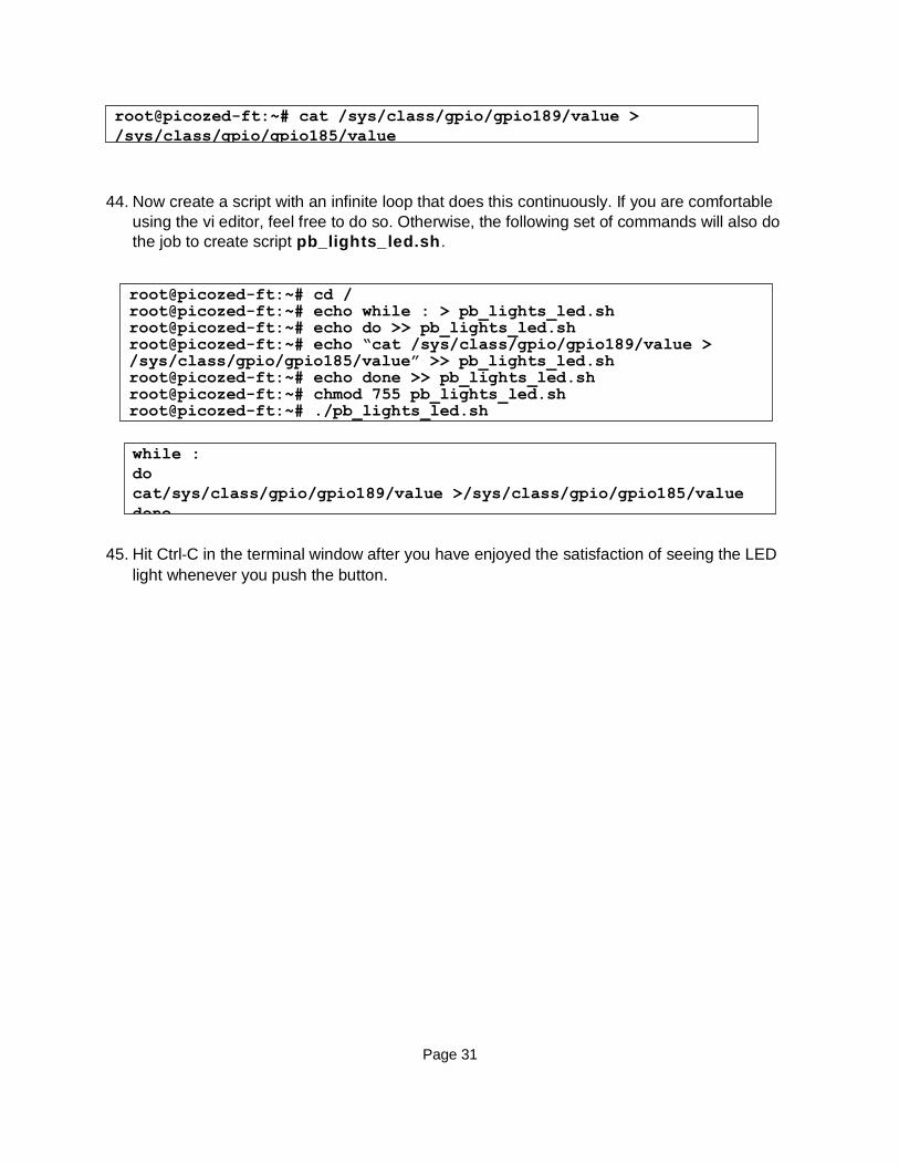
44. Now create a script with an infinite loop that does this continuously. If you are comfortable
using the vi editor, feel free to do so. Otherwise, the following set of commands will also do
the job to create script pb_lights_led.sh.
45. Hit Ctrl‐C in the terminal window after you have enjoyed the satisfaction of seeing the LED
light whenever you push the button.
root@picozed-ft:~# cat /sys/class/gpio/gpio189/value >
/sys/class/gpio/gpio185/value
root@picozed-ft:~# cd / root@picozed-ft:~# echo while : > pb_lights_led.sh root@picozed-ft:~# echo do >> pb_lights_led.sh root@picozed-ft:~# echo “cat /sys/class/gpio/gpio189/value > /sys/class/gpio/gpio185/value” >> pb_lights_led.sh root@picozed-ft:~# echo done >> pb_lights_led.sh root@picozed-ft:~# chmod 755 pb_lights_led.sh root@picozed-ft:~# ./pb_lights_led.sh
while :
do
cat/sys/class/gpio/gpio189/value >/sys/class/gpio/gpio185/value
done
Page 32
10 Ethernet Operations The PicoZed example Linux system implements ftpd FTP server and Busybox httpd HTTP server at startup. Refer to the documentation on each of these server implementations if you are interested in using them beyond the scope of this document.
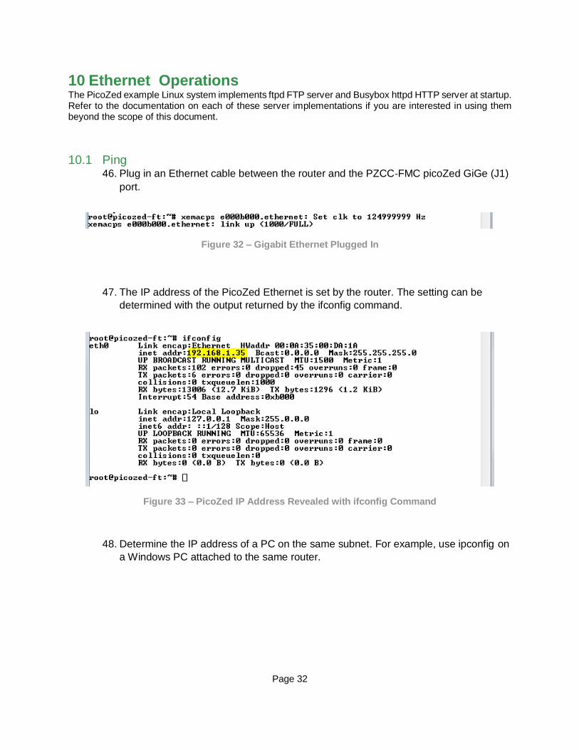
10.1 Ping 46. Plug in an Ethernet cable between the router and the PZCC‐FMC picoZed GiGe (J1)
port.
Figure 32 – Gigabit Ethernet Plugged In
47. The IP address of the PicoZed Ethernet is set by the router. The setting can be
determined with the output returned by the ifconfig command.
Figure 33 – PicoZed IP Address Revealed with ifconfig Command
48. Determine the IP address of a PC on the same subnet. For example, use ipconfig on
a Windows PC attached to the same router.
Page 31
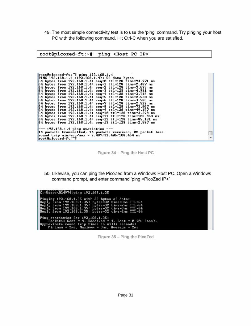
49. The most simple connectivity test is to use the ‘ping’ command. Try pinging your host
PC with the following command. Hit Ctrl‐C when you are satisfied.
Figure 34 – Ping the Host PC
50. Likewise, you can ping the PicoZed from a Windows Host PC. Open a Windows
command prompt, and enter command ‘ping <PicoZed IP>’
Figure 35 – Ping the PicoZed
root@picozed-ft:~# ping <Host PC IP>

Page 32
10.2 Web Server 51. To view the PetaLinux embedded webpage, open a web browser on the host PC and
browse to the PicoZed IP address http://<PicoZed IP>/ as the URL. The webpage
should open in the browser. This is the default webserver provided through the Xilinx
distribution.
Figure 36 – PicoZed Webpage Shown In PC Host Browser
10.3 FTP 52. Open a Windows Command Prompt.
53. Connect an FTP session to the remote host with the command ftp <PicoZed IP> and
use the login root. You can use the ftp session to transfer files back and forth across
the network to PicoZed.
54. Close the ftp session using the quit command.
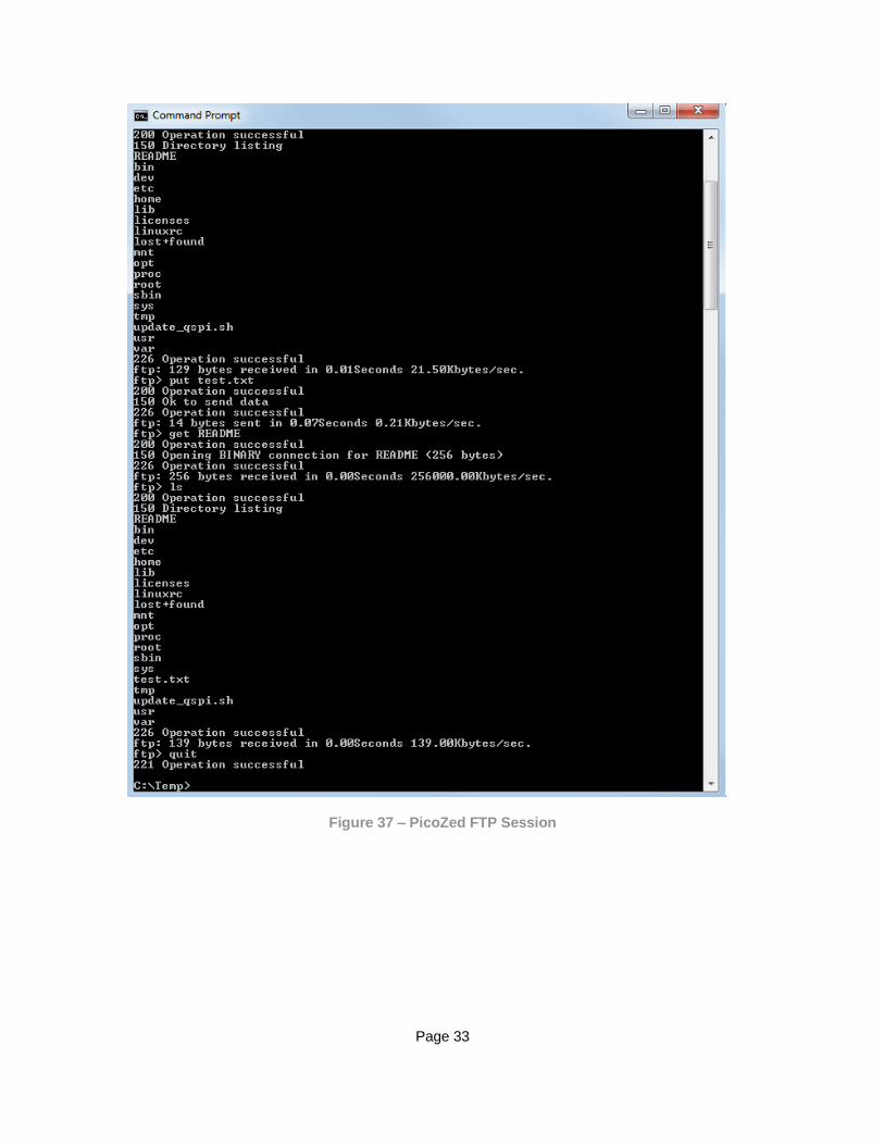
Page 33
Figure 37 – PicoZed FTP Session
Page 34
11 Mass Storage: USB‐Host, microSD Card, eMMC This demo shows the mass storage options that the PicoZed FMC Carrier system has readily available. This includes 4GB of built‐in eMMC that was previously formatted at the factory. A 4GB microSD card is
also included with the kit.
Additionally, PicoZed includes a high speed USB communications peripheral connected to the Processing System (PS) of Zynq‐7000 AP SoC. The PZCC‐FMC / PicoZed USB 2.0 is designed to be configured as
Host, Device, or OTG, with the default jumper settings for JP3 and JP4 configuring it for Host. In this state, a simple USB thumb drive can be plugged in to provide mass storage using the provided USB micro to Type A adapter.
Note: PicoZed only has one USB 2.0 port. To connect multiple USB devices with the PZCC‐ FMC, connect
a powered hub to the USB‐Host port. USB devices attached to this hub can then also be accessed in Linux.
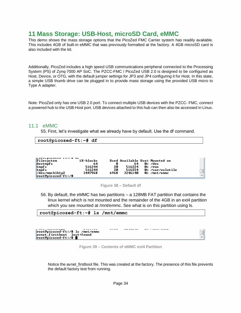
11.1 eMMC 55. First, let’s investigate what we already have by default. Use the df command.
Figure 38 – Default df
56. By default, the eMMC has two partitions – a 128MB FAT partition that contains the
linux kernel which is not mounted and the remainder of the 4GB in an ext4 partition
which you see mounted at /mnt/emmc. See what is on this partition using ls.
Figure 39 – Contents of eMMC ext4 Partition
Notice the avnet_firstboot file. This was created at the factory. The presence of this file prevents the default factory test from running.
root@picozed-ft:~# df
root@picozed-ft:~# ls /mnt/emmc

Page 35
11.2 USB Memory Stick NOTE: Due to an erratum, only 128 mA is available to the USB Host port. If you have a very low power USB device, it will work. Otherwise, you should plug a power USB hub into the PicoZed FMC Carrier, and then plug the USB Memory Stick into the hub.
57. Connect a USB memory stick (not included in the PicoZed FMC Carrier Kit) to your
PC. Format as FAT32 or NTFS. Create a simple text file on the memory stick then
eject from the PC.
58. Connect the USB memory stick to the included Male Micro‐B to Female Standard‐A
USB adapter. Then connect the adapter to the PZCC‐FMC USB_OTG microUSB
connector (J5).
59. The USB memory stick should enumerate and the device indication should display
on the serial console. As shown in Figure 40, the primary partition of the USB
memory stick is enumerated as device /dev/sda.
Figure 40 – USB Drive Enumerated as /dev/sda
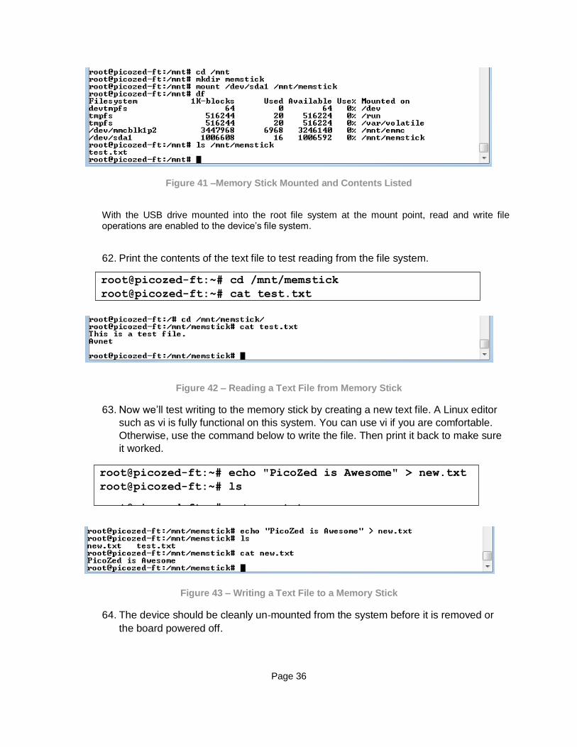
60. Create a new mount point for both the memory stick
61. Mount the enumerated USB device to the /mnt/memstick mount point and check the
contents. Depending on what you saw on the screen (sda or sda1), you will need to
select the appropriate commands below. In this example, the memory stick has one
file (test.txt) that was previously copied to the memory stick.
For /dev/sda
For /dev/sda1
root@picozed-ft:~# cd /mnt
root@picozed-ft:~# mkdir memstick
root@picozed-ft:~# mount /dev/sda /mnt/memstick
root@picozed-ft:~# df
root@picozed-ft:~# ls /mnt/memstick
root@picozed-ft:~# mount /dev/sda1 /mnt/memstick
root@picozed-ft:~# ls /mnt/memstick
Page 36
Figure 41 –Memory Stick Mounted and Contents Listed
With the USB drive mounted into the root file system at the mount point, read and write file operations are enabled to the device’s file system.
62. Print the contents of the text file to test reading from the file system.
Figure 42 – Reading a Text File from Memory Stick
63. Now we’ll test writing to the memory stick by creating a new text file. A Linux editor
such as vi is fully functional on this system. You can use vi if you are comfortable.
Otherwise, use the command below to write the file. Then print it back to make sure
it worked.
Figure 43 – Writing a Text File to a Memory Stick
64. The device should be cleanly un‐mounted from the system before it is removed or
the board powered off.
root@picozed-ft:~# echo "PicoZed is Awesome" > new.txt
root@picozed-ft:~# ls
root@picozed-ft:~# cat new.txt
root@picozed-ft:~# cd /mnt/memstick
root@picozed-ft:~# cat test.txt

Page 37
Note: If the device cannot be un‐mounted or if a “Device or resource busy” message is shown,
make sure that no files or folders of the mounted file system are currently open or that the current working directory is not part of the mounted file system.
65. Remove the memory stick. Plug it into the PC and verify the new.txt file is there.
11.3 SD Card 66. Create a new mount point for both the memory stick and the sdcard
67. Now mount the SD card and check to see if it mounted properly.
Figure 44 – SD Card Successfully Mounted
68. Repeat steps 63 through 65 for the microSD card and mount point /mnt/sdcard.
root@picozed-ft:~# cd /mnt
root@picozed-ft:~# umount memstick
root@picozed-ft:~# cd /mnt
root@picozed-ft:~# mkdir sdcard
root@picozed-ft:~# mount /dev/mmcblk0p1 /mnt/sdcard/
root@picozed-ft:~# df

Page 38
12 HDMI The default factory image generates and displays a static test image on the HDMI port.
69. Plug an HDMI cable into the PZCC‐FMC HDMI Port (J10) and an HDMI monitor.
70. The HDMI monitor should display the following image below
Figure 45 – HDMI Test Pattern

Page 39
13 Poweroff When you are done experimenting, power off Linux and the boards.
71. Linux should be properly shut‐down.
Figure 46 – PicoZed Linux Shutdown
72. Turn the power switch (SW7) to the OFF position.
To further examine PicoZed and the PicoZed FMC Carrier, please go to www.picozed.org → Support → Reference Designs/Tutorials → PicoZed FMC Carrier
To complete the tutorials, you will need to install Xilinx development tools. For instructions on installing the Xilinx software, please refer to Appendix B: Installing and Licensing Xilinx Software.
root@picozed-ft:~# poweroff

Page 40
14 Getting Help and Support
14.1 Avnet Support The PZCC‐FMC is a versatile development kit that allows evaluation of the PicoZed SOM, which
can help you adopt PicoZed into your next design. All technical support is offered through the PicoZed.org website support forums. PicoZed users are encouraged to participate in the forums and offer help to others when possible. http://picozed.org/forums/
For questions regarding the PicoZed community website, please direct any questions to: PicoZed.org Web Master – [email protected]
To access the most current collateral for PicoZed please visit the community support page at: www.PicoZed.org/content/support
Once on the PicoZed.org support page:
To access the latest PicoZed documentation, click on the Documentation link:
To access the latest reference designs for PicoZed, click on the following link:

Page 41
To access the PicoZed technical forums, click on the following link:
To view online training and videos, click on the following link:

Page 42
14.2 Xilinx Support For questions regarding products within the Product Entitlement Account, send an e‐ mail message
to the Customer Service Representative in your region:
Canada, USA and South America ‐ [email protected]
Europe, Middle East, and Africa ‐ [email protected]
Asia Pacific including Japan ‐ [email protected]
For technical support including the installation and use of the product license file, contact Xilinx Online Technical Support at www.xilinx.com/support. The following assistance resources are also available on the website:
– Software, IP and documentation updates
– Access to technical support web tools
– Searchable answer database with over 4,000 solutions
– User forums
Page 43
15 Appendix A: Format the microSD Card
The PicoZed Evaluation Kit ships with a blank microSD card. To ensure it is ready to be used in Linux and later as a boot source, it must be properly formatted. To use the microSD card as a boot device, it must be formatted as FAT32.
The following operations were performed on a Windows 7 PC using a built‐in SD Card slot. If an SD Card
slot is not available on your PC, you will need to purchase an SD Card device or a USB‐based microSD
adapter.
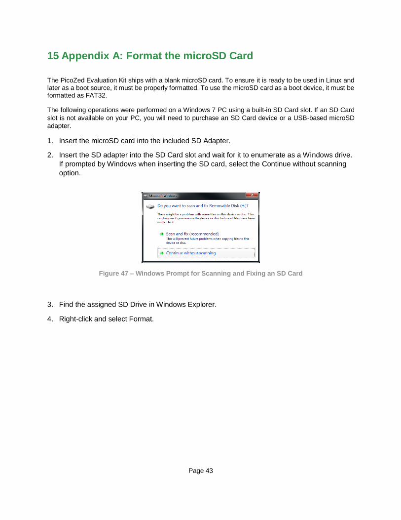
1. Insert the microSD card into the included SD Adapter.
2. Insert the SD adapter into the SD Card slot and wait for it to enumerate as a Windows drive.
If prompted by Windows when inserting the SD card, select the Continue without scanning
option.
Figure 47 – Windows Prompt for Scanning and Fixing an SD Card
3. Find the assigned SD Drive in Windows Explorer.
4. Right‐click and select Format.

Page 44
5. Select the File System to be FAT32. The Allocation unit size can be set to Default. Click
Start.
Figure 48 – Format the microSD Card
6. As stated in the warning dialog, formatting will erase all data on the disk. Click OK.
Figure 49 – Formatting Will Erase

Page 45
7. If all goes well, you will get a message stating Format Complete. Click OK.
Figure 50 – Format Complete
8. Click Close in the Format dialog box.
9. To double‐check your card, right‐click on the drive in Windows Explorer and select
Properties. Notice the File system displayed as FAT32. Click OK to close.
Figure 51 – Properties of the microSD Drive
Page 46
16 Appendix B: Installing and Licensing Xilinx Software
16.1 Install Vivado Design Suite, WebPack Edition The four Zynq devices available within the PicoZed SOM family are all supported in Vivado Design Suite, WebPack Edition. See www.xilinx.com/products/design‐tools/vivado/vivado‐webpack.html
This software can be downloaded online at: www.xilinx.com/support/download/index.htm
You can also request a free DVD from www.xilinx.com/onlinestore/dvd_fulfillment_request‐vivado.htm
Although free, WebPack still must be licensed. To obtain your free license, visit http://www.xilinx.com/getlicense
If a full seat of Vivado System or Design Edition has already been installed, then no further software will be needed. Please check online for any updates at: www.xilinx.com/support/download/index.htm
For detailed instructions on installing and licensing the Xilinx tools, please refer to the latest version of Vivado Design Suite User Guide Release Notes, Installation, and Licensing (UG973). The 2015.2 version is available on the Xilinx website at: www.xilinx.com/support/documentation/sw_manuals/xilinx2015_2/ug973‐vivado‐release‐notes‐install‐license.pdf