Embed Size (px)
Citation preview
Booting PicoZed using QSPI and eMMC
Version 2.0 April 2015
Xilinx Tool Version 2014.4
Booting PicoZed using QSPI and eMMC Vivado®/SDK 2014.4
1 April 30, 2015
Table of Contents Introduction .................................................................................................................................................. 2 Objectives ..................................................................................................................................................... 3 Reference Design Requirements .................................................................................................................. 3
Software ................................................................................................................................................... 3 Hardware .................................................................................................................................................. 3
Boot Files in the PetaLinux BSP ..................................................................................................................... 4 Setting up the PicoZed and Carrier ............................................................................................................... 5
Installing the UART Driver and Virtual COM Port ..................................................................................... 9 Installing a Serial Console on a Windows 7 Host ...................................................................................... 9
Vivado Hardware Design Requirements ..................................................................................................... 10 Using a PetaLinux Board Support Package (BSP) ........................................................................................ 11
Install and Test the PetaLinux BSP .......................................................................................................... 11 Create a PetaLinux Project for the Target Platform (without BSP) ........................................................ 12
Booting Linux from SD card ........................................................................................................................ 14 Configure PetaLinux for SD Boot ............................................................................................................ 14 Copy Images to SD Card and Boot .......................................................................................................... 18
Booting Linux from QSPI ............................................................................................................................. 19 Modify u-boot for QSPI ........................................................................................................................... 19
Add Serial Flash Commands to u-boot ............................................................................................... 20 Configure PetaLinux for QSPI Boot ..................................................................................................... 20 Program the QSPI Flash and Boot ...................................................................................................... 22 Erasing MTD Partitions ....................................................................................................................... 24
Changing MTD Partitions ........................................................................................................................ 25 Prepare the eMMC Memory for Operation ................................................................................................ 28
Boot PetaLinux from SD Card ................................................................................................................. 28 Partition and Format the eMMC ............................................................................................................ 29 Copy Secondary Boot Files to eMMC ..................................................................................................... 31
Configure and Build PetaLinux to Boot from QSPI and eMMC ................................................................... 32 Moving the Bitstream to eMMC ............................................................................................................. 34
Appendix I: Installation of USB UART Driver .............................................................................................. 37 Download and Install the Required Software (for Windows) ................................................................ 37 Determining the Virtual COM Port (on Windows) ................................................................................. 39
Revision History .......................................................................................................................................... 40
Booting PicoZed using QSPI and eMMC Vivado®/SDK 2014.4
2 April 30, 2015
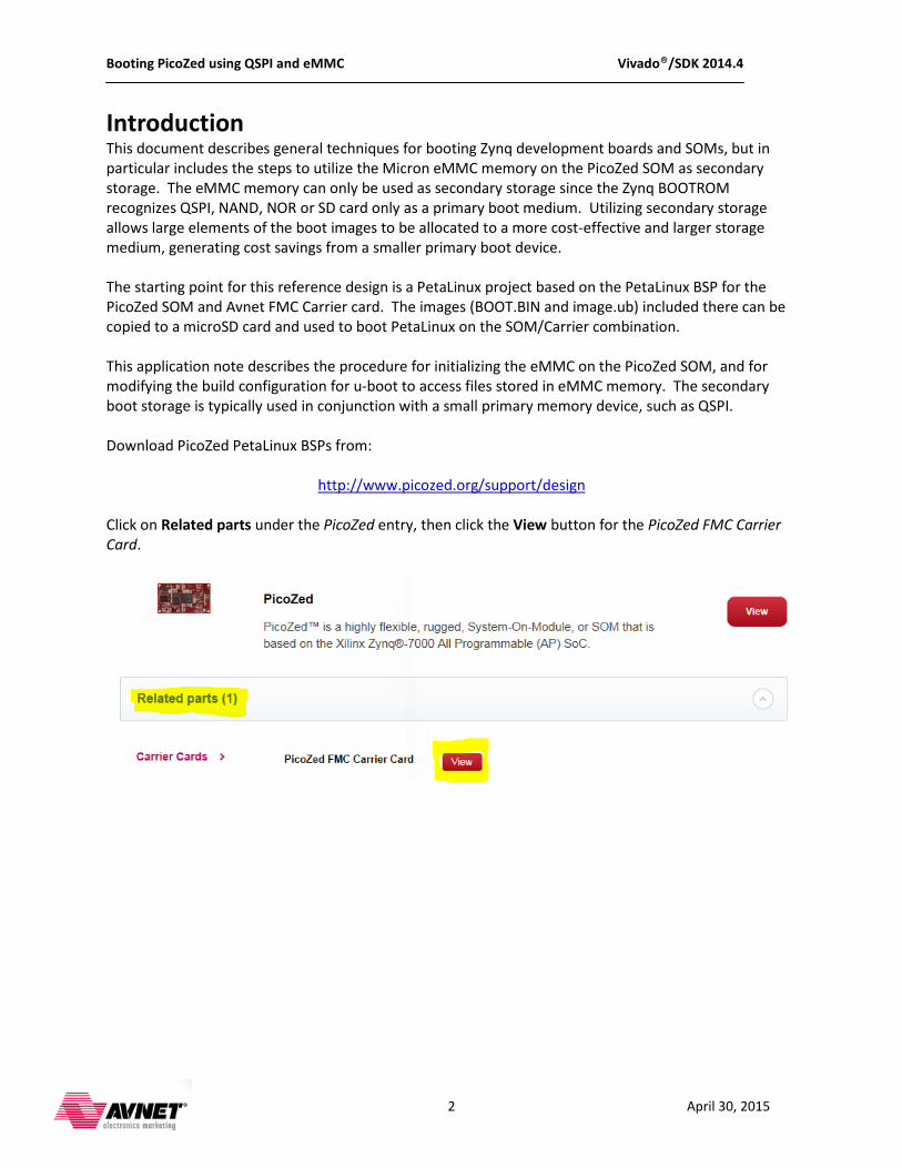
Introduction This document describes general techniques for booting Zynq development boards and SOMs, but in particular includes the steps to utilize the Micron eMMC memory on the PicoZed SOM as secondary storage. The eMMC memory can only be used as secondary storage since the Zynq BOOTROM recognizes QSPI, NAND, NOR or SD card only as a primary boot medium. Utilizing secondary storage allows large elements of the boot images to be allocated to a more cost-effective and larger storage medium, generating cost savings from a smaller primary boot device. The starting point for this reference design is a PetaLinux project based on the PetaLinux BSP for the PicoZed SOM and Avnet FMC Carrier card. The images (BOOT.BIN and image.ub) included there can be copied to a microSD card and used to boot PetaLinux on the SOM/Carrier combination. This application note describes the procedure for initializing the eMMC on the PicoZed SOM, and for modifying the build configuration for u-boot to access files stored in eMMC memory. The secondary boot storage is typically used in conjunction with a small primary memory device, such as QSPI. Download PicoZed PetaLinux BSPs from:
http://www.picozed.org/support/design
Click on Related parts under the PicoZed entry, then click the View button for the PicoZed FMC Carrier Card.

Booting PicoZed using QSPI and eMMC Vivado®/SDK 2014.4
3 April 30, 2015
Objectives This application note describes how to: • Modify a hardware design to ensure the eMMC can be accessed by a standard PetaLinux kernel • Use PetaLinux to prepare the eMMC memory for first-time use • Modify u-boot to read boot images from eMMC memory • Create a primary BOOT.BIN image and load it to QSPI memory • Boot the PicoZed/Carrier combination to the PetaLinux command prompt using QSPI and eMMC
Reference Design Requirements
Software The software requirements for this reference design are: • 64-bit Linux (can be Linux installed in a virtual machine on a 64-bit Windows host) • PetaLinux Tools 2014.4 • Silicon Labs CP2102 USB-UART bridge • Serial terminal emulation software such as TeraTerm • PetaLinux 2014.4 BSP for PicoZed SOM/Carrier combination
Hardware The hardware requirements for this reference design are: • Avnet PicoZed SOM (7z010, 7z015, 7z020 or 7z030) • Avnet PicoZed FMC Carrier Card and 12v power supply • microSD card minimum 4 GB/class 4, formatted FAT32 • USB-A to USB-micro B cable for USB UART • Host PC with 10/100/1000 compatible Ethernet NIC • Cat-5 Ethernet cable (optional) • Host PC or network router to act as DHCP server (optional) The instructions in this document include details for modifying specific files in the PetaLinux project to customize the resulting output for any Zynq board. If you are working from a BSP, you will find that all the required updates for your version of the PicoZed/Carrier combination have already been provided for you. However, if you ever wish to recreate a BSP from scratch, or understand how the BSP was modified from the default, you can follow the instructions to achieve the desired customization.
Booting PicoZed using QSPI and eMMC Vivado®/SDK 2014.4
4 April 30, 2015
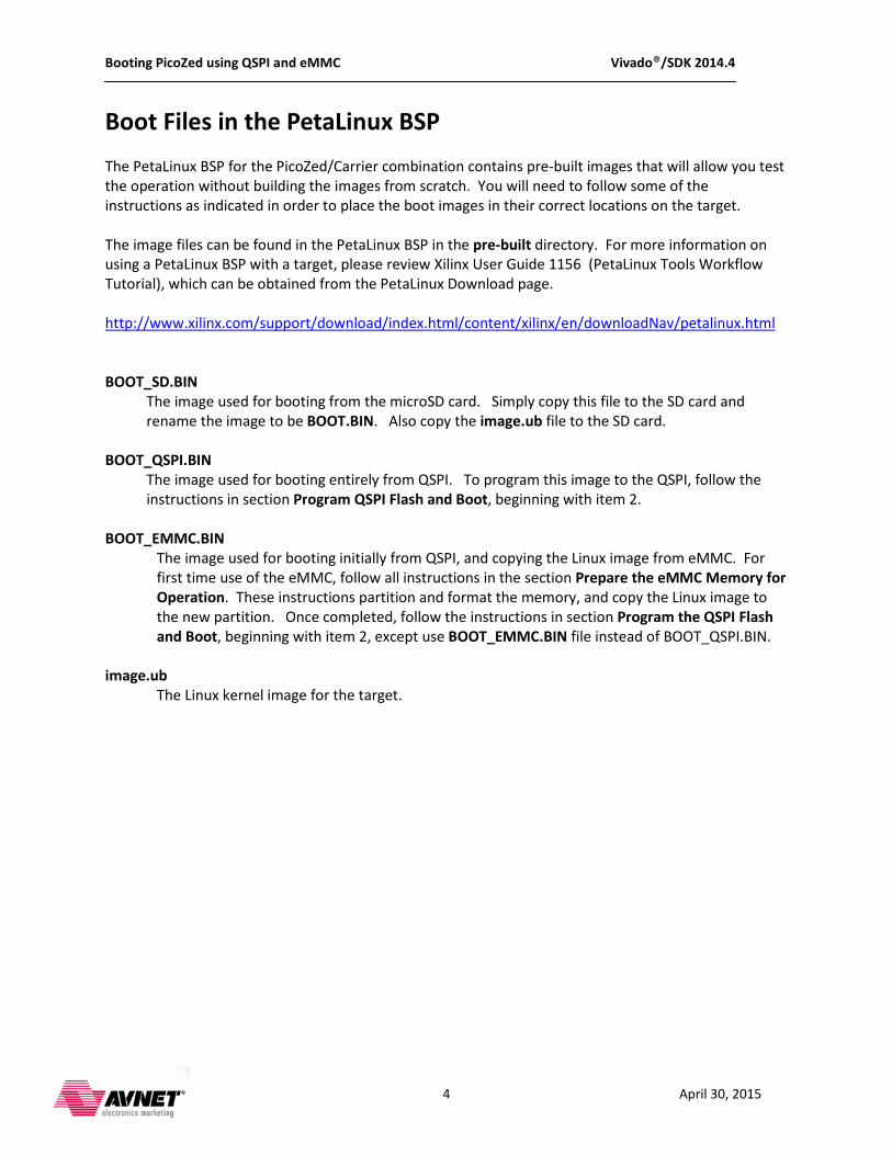
Boot Files in the PetaLinux BSP The PetaLinux BSP for the PicoZed/Carrier combination contains pre-built images that will allow you test the operation without building the images from scratch. You will need to follow some of the instructions as indicated in order to place the boot images in their correct locations on the target. The image files can be found in the PetaLinux BSP in the pre-built directory. For more information on using a PetaLinux BSP with a target, please review Xilinx User Guide 1156 (PetaLinux Tools Workflow Tutorial), which can be obtained from the PetaLinux Download page. http://www.xilinx.com/support/download/index.html/content/xilinx/en/downloadNav/petalinux.html BOOT_SD.BIN
The image used for booting from the microSD card. Simply copy this file to the SD card and rename the image to be BOOT.BIN. Also copy the image.ub file to the SD card.
BOOT_QSPI.BIN The image used for booting entirely from QSPI. To program this image to the QSPI, follow the instructions in section Program QSPI Flash and Boot, beginning with item 2.
BOOT_EMMC.BIN The image used for booting initially from QSPI, and copying the Linux image from eMMC. For first time use of the eMMC, follow all instructions in the section Prepare the eMMC Memory for Operation. These instructions partition and format the memory, and copy the Linux image to the new partition. Once completed, follow the instructions in section Program the QSPI Flash and Boot, beginning with item 2, except use BOOT_EMMC.BIN file instead of BOOT_QSPI.BIN.
image.ub The Linux kernel image for the target.
Booting PicoZed using QSPI and eMMC Vivado®/SDK 2014.4
5 April 30, 2015
Setting up the PicoZed and Carrier The PicoZed family of SOMs consists of four members:
1. Zynq 7010 SOM 2. Zynq 7015 SOM 3. Zynq 7020 SOM 4. Zynq 7030 SOM
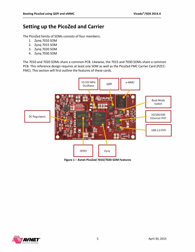
The 7010 and 7020 SOMs share a common PCB. Likewise, the 7015 and 7030 SOMs share a common PCB. This reference design requires at least one SOM as well as the PicoZed FMC Carrier Card (PZCC-FMC). This section will first outline the features of these cards.
Figure 1 – Avnet PicoZed 7010/7020 SOM Features
Booting PicoZed using QSPI and eMMC Vivado®/SDK 2014.4
6 April 30, 2015
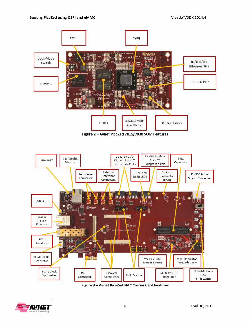
Figure 2 – Avnet PicoZed 7015/7030 SOM Features
Figure 3 – Avnet PicoZed FMC Carrier Card Features
Booting PicoZed using QSPI and eMMC Vivado®/SDK 2014.4
7 April 30, 2015
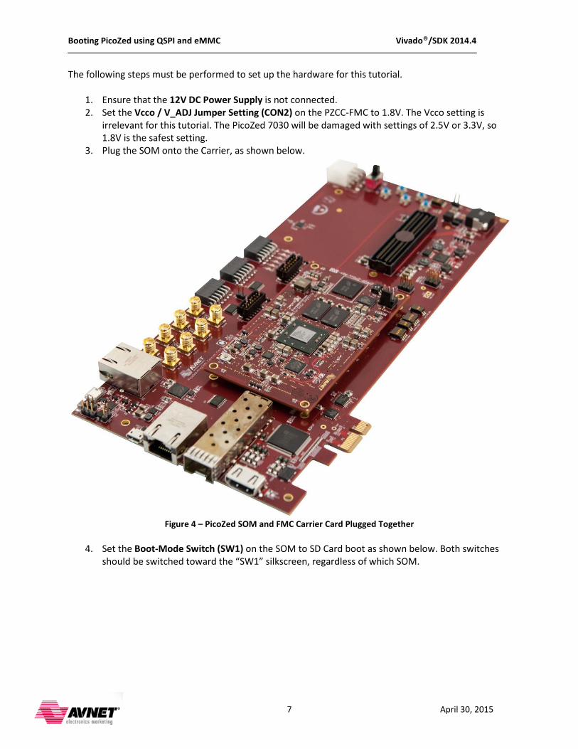
The following steps must be performed to set up the hardware for this tutorial.
1. Ensure that the 12V DC Power Supply is not connected. 2. Set the Vcco / V_ADJ Jumper Setting (CON2) on the PZCC-FMC to 1.8V. The Vcco setting is
irrelevant for this tutorial. The PicoZed 7030 will be damaged with settings of 2.5V or 3.3V, so 1.8V is the safest setting.
3. Plug the SOM onto the Carrier, as shown below.
Figure 4 – PicoZed SOM and FMC Carrier Card Plugged Together
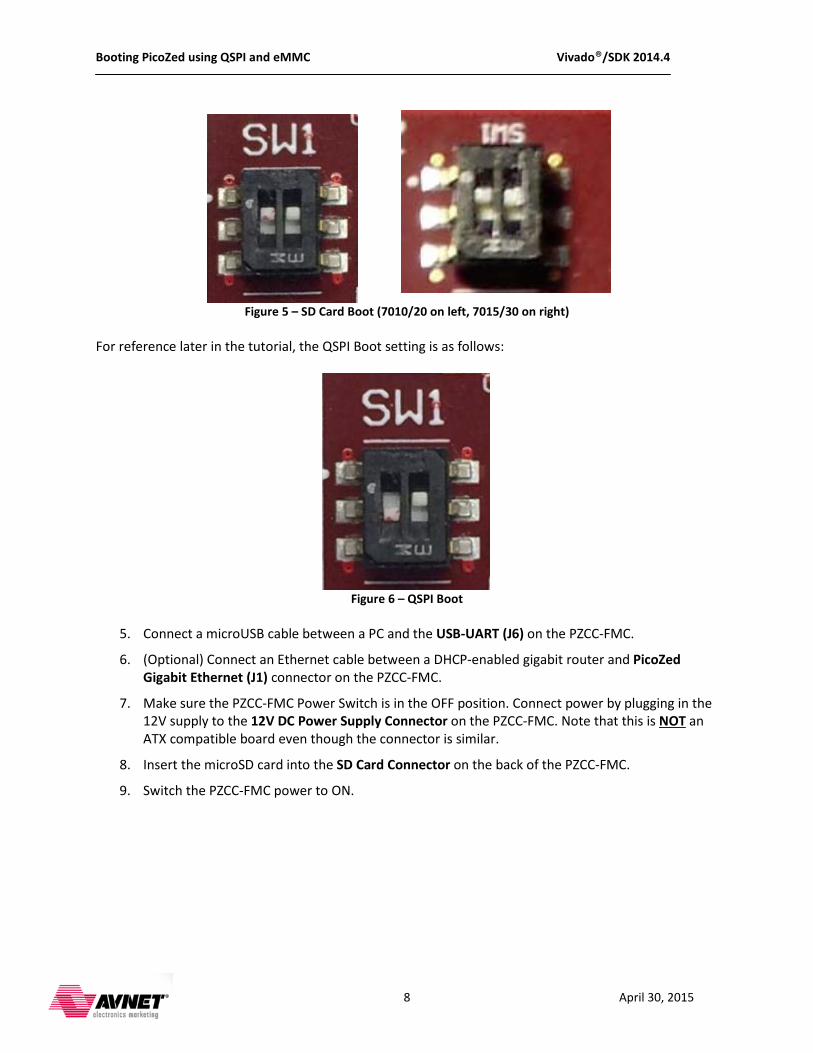
4. Set the Boot-Mode Switch (SW1) on the SOM to SD Card boot as shown below. Both switches
should be switched toward the “SW1” silkscreen, regardless of which SOM.
Booting PicoZed using QSPI and eMMC Vivado®/SDK 2014.4
8 April 30, 2015
Figure 5 – SD Card Boot (7010/20 on left, 7015/30 on right)
For reference later in the tutorial, the QSPI Boot setting is as follows:
Figure 6 – QSPI Boot
5. Connect a microUSB cable between a PC and the USB-UART (J6) on the PZCC-FMC.
6. (Optional) Connect an Ethernet cable between a DHCP-enabled gigabit router and PicoZed Gigabit Ethernet (J1) connector on the PZCC-FMC.
7. Make sure the PZCC-FMC Power Switch is in the OFF position. Connect power by plugging in the 12V supply to the 12V DC Power Supply Connector on the PZCC-FMC. Note that this is NOT
8. Insert the microSD card into the SD Card Connector on the back of the PZCC-FMC.
an ATX compatible board even though the connector is similar.
9. Switch the PZCC-FMC power to ON.
Booting PicoZed using QSPI and eMMC Vivado®/SDK 2014.4
9 April 30, 2015
Installing the UART Driver and Virtual COM Port If the PicoZed/Carrier have not been connected to the host PC before, it may be necessary to install the software driver for the virtual COM port. The driver installation for the Silicon Labs CP2102 USB-UART bridge is described in detail in Appendix I: Installation of USB UART Driver.
Installing a Serial Console on a Windows 7 Host Starting with Windows 7, Microsoft no longer includes the HyperTerminal terminal emulator software. This example design requires use of terminal emulation software for a serial console connection to the target. A suitable free and open-source replacement for HyperTerminal is TeraTerm. A download link for TeraTerm is:
http://en.sourceforge.jp/projects/ttssh2
Booting PicoZed using QSPI and eMMC Vivado®/SDK 2014.4
10 April 30, 2015
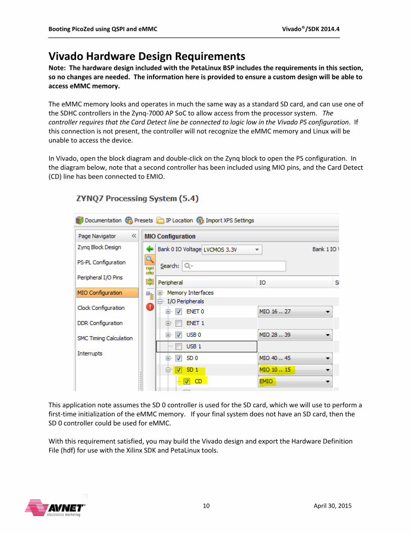
Vivado Hardware Design Requirements Note: The hardware design included with the PetaLinux BSP includes the requirements in this section, so no changes are needed. The information here is provided to ensure a custom design will be able to access eMMC memory. The eMMC memory looks and operates in much the same way as a standard SD card, and can use one of the SDHC controllers in the Zynq-7000 AP SoC to allow access from the processor system. The controller requires that the Card Detect line be connected to logic low in the Vivado PS configuration. If this connection is not present, the controller will not recognize the eMMC memory and Linux will be unable to access the device. In Vivado, open the block diagram and double-click on the Zynq block to open the PS configuration. In the diagram below, note that a second controller has been included using MIO pins, and the Card Detect (CD) line has been connected to EMIO.
This application note assumes the SD 0 controller is used for the SD card, which we will use to perform a first-time initialization of the eMMC memory. If your final system does not have an SD card, then the SD 0 controller could be used for eMMC. With this requirement satisfied, you may build the Vivado design and export the Hardware Definition File (hdf) for use with the Xilinx SDK and PetaLinux tools.
Booting PicoZed using QSPI and eMMC Vivado®/SDK 2014.4
11 April 30, 2015
Using a PetaLinux Board Support Package (BSP)
Install and Test the PetaLinux BSP For complete instructions to install and test a PetaLinux BSP, consult Xilinx UG1156. Brief instructions for readers with previous PetaLinux experience are provided here.
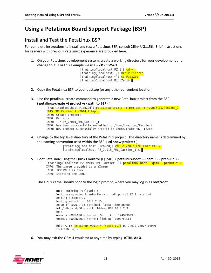
1. On your PetaLinux development system, create a working directory for your development and change to it. For this example we use ~/PicoZed.
2. Copy the PetaLinux BSP to your desktop (or any other convenient location).
3. Use the petalinux-create command to generate a new PetaLinux project from the BSP. ( petalinux-create –t project –s <path to BSP> )
4. Change to the top level directory of the PetaLinux project. The directory name is determined by the naming convention used within the BSP. ( cd <new project> )
5. Boot PetaLinux using the Quick Emulator (QEMU). ( petalinux-boot - - qemu - - prebuilt 3 )
The Linux kernel should boot to the login prompt, where you may log in as root/root.
6. You may exit the QEMU emulator at any time by typing <CTRL-A> X.

Booting PicoZed using QSPI and eMMC Vivado®/SDK 2014.4
12 April 30, 2015
Create a PetaLinux Project for the Target Platform (without BSP) For detailed information on this procedure, consult Xilinx UG1144 – PetaLinux Tools Reference Guide. For those with some experience, the overview steps provided here assume:
• You have a validated Vivado hardware design • You have exported the Hardware Definition File (hdf) to the Xilinx SDK and have created a Zynq
FSBL application ELF file. • You either have the SDK project, or you have the hdf and zynq_FSBL.elf file on your Linux
development platform.
1. Create a new PetaLinux project in your working directory. ( petalinux-create - -type project - -template zynq - -name <project_name> )
2. Change to the directory containing the SDK project, or to the directory containing the hdf archive. Note that the path names for your BSP may differ from this example. ( cd <hdf path> )
3. Import the hardware platform from the current directory, targeting the new PetaLinux project created in step 1. ( petalinux-config - -get-hw-description -p <path to PetaLinux project> )
This will automatically launch the menuconfig utility as shown on the next page. Experienced users may leave the configuration open and proceed to a specific boot section within this document. The last steps in this section simply close the utility so that we have a common starting point for the specific boot sections. The project name and location used as the default for the remainder of this document is:
~/PicoZed/PZ_7z015_FMC
Booting PicoZed using QSPI and eMMC Vivado®/SDK 2014.4
13 April 30, 2015
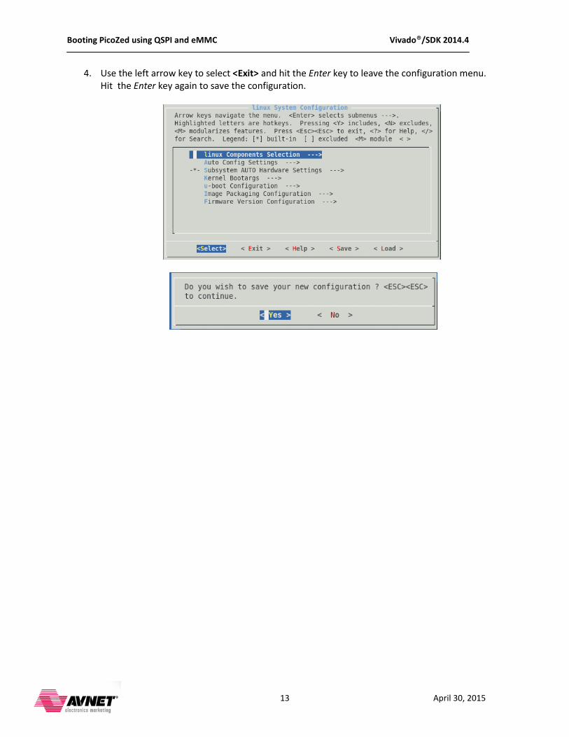
4. Use the left arrow key to select <Exit> and hit the Enter key to leave the configuration menu. Hit the Enter key again to save the configuration.
Booting PicoZed using QSPI and eMMC Vivado®/SDK 2014.4
14 April 30, 2015
Booting Linux from SD card This is the simplest boot procedure, and is the starting point for development and all other boot methods.
Configure PetaLinux for SD Boot
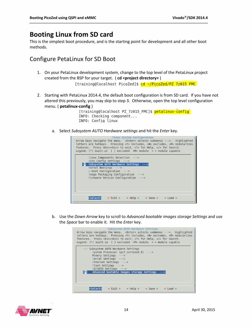
1. On your PetaLinux development system, change to the top level of the PetaLinux project created from the BSP for your target. ( cd <project directory> )
2. Starting with PetaLinux 2014.4, the default boot configuration is from SD card. If you have not altered this previously, you may skip to step 3. Otherwise, open the top level configuration menu. ( petalinux-config )
a. Select Subsystem AUTO Hardware settings and hit the Enter key.
b. Use the Down Arrow key to scroll to Advanced bootable images storage Settings and use the Space bar to enable it. Hit the Enter key.
Booting PicoZed using QSPI and eMMC Vivado®/SDK 2014.4
15 April 30, 2015
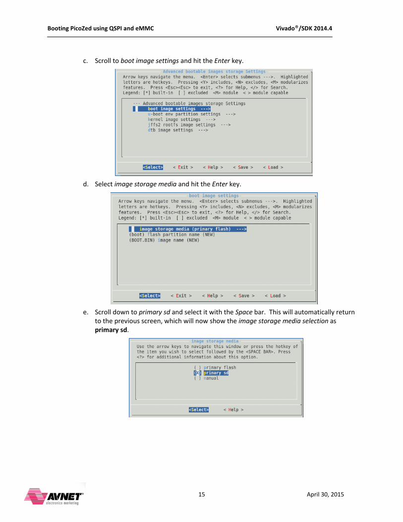
c. Scroll to boot image settings and hit the Enter key.
d. Select image storage media and hit the Enter key.
e. Scroll down to primary sd and select it with the Space bar. This will automatically return
to the previous screen, which will now show the image storage media selection as primary sd.
Booting PicoZed using QSPI and eMMC Vivado®/SDK 2014.4
16 April 30, 2015
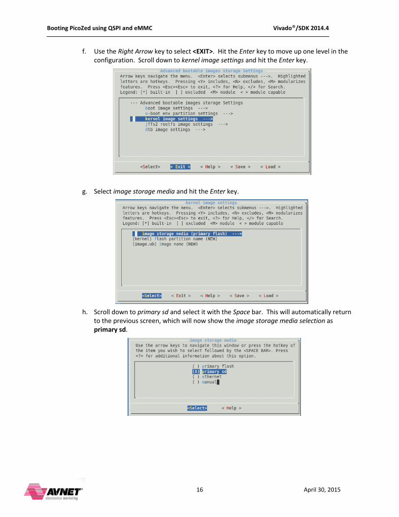
f. Use the Right Arrow key to select <EXIT>. Hit the Enter key to move up one level in the configuration. Scroll down to kernel image settings and hit the Enter key.
g. Select image storage media and hit the Enter key.
h. Scroll down to primary sd and select it with the Space bar. This will automatically return
to the previous screen, which will now show the image storage media selection as primary sd.
Booting PicoZed using QSPI and eMMC Vivado®/SDK 2014.4
17 April 30, 2015
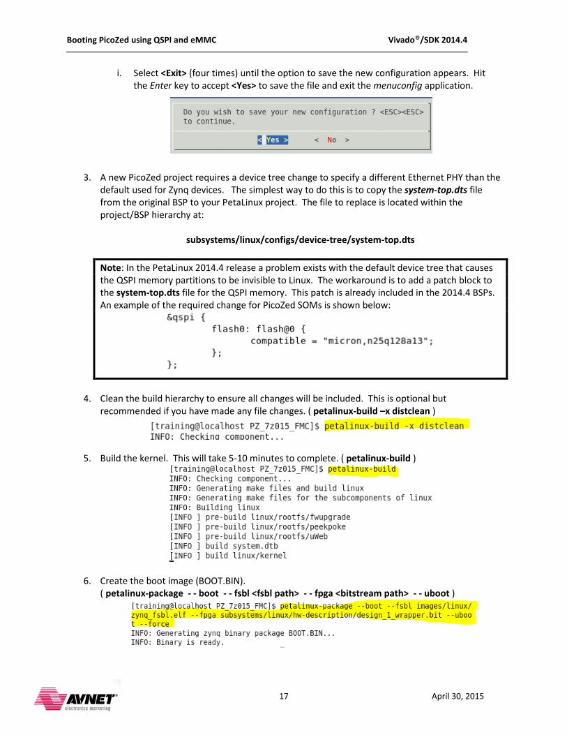
i. Select <Exit> (four times) until the option to save the new configuration appears. Hit the Enter key to accept <Yes> to save the file and exit the menuconfig application.
3. A new PicoZed project requires a device tree change to specify a different Ethernet PHY than the default used for Zynq devices. The simplest way to do this is to copy the system-top.dts file from the original BSP to your PetaLinux project. The file to replace is located within the project/BSP hierarchy at:
subsystems/linux/configs/device-tree/system-top.dts
Note: In the PetaLinux 2014.4 release a problem exists with the default device tree that causes the QSPI memory partitions to be invisible to Linux. The workaround is to add a patch block to the system-top.dts file for the QSPI memory. This patch is already included in the 2014.4 BSPs. An example of the required change for PicoZed SOMs is shown below:
4. Clean the build hierarchy to ensure all changes will be included. This is optional but recommended if you have made any file changes. ( petalinux-build –x distclean )
5. Build the kernel. This will take 5-10 minutes to complete. ( petalinux-build )
6. Create the boot image (BOOT.BIN). ( petalinux-package - - boot - - fsbl <fsbl path> - - fpga <bitstream path> - - uboot )
Booting PicoZed using QSPI and eMMC Vivado®/SDK 2014.4
18 April 30, 2015
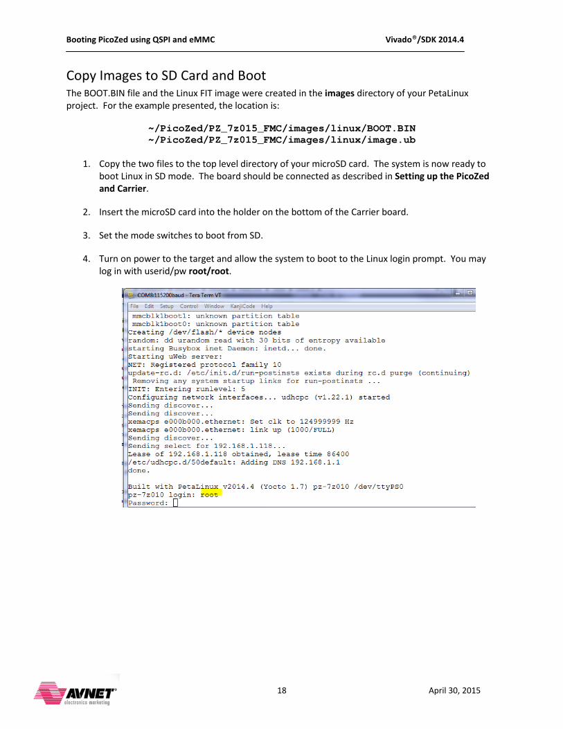
Copy Images to SD Card and Boot The BOOT.BIN file and the Linux FIT image were created in the images directory of your PetaLinux project. For the example presented, the location is:
~/PicoZed/PZ_7z015_FMC/images/linux/BOOT.BIN ~/PicoZed/PZ_7z015_FMC/images/linux/image.ub
1. Copy the two files to the top level directory of your microSD card. The system is now ready to
boot Linux in SD mode. The board should be connected as described in Setting up the PicoZed and Carrier.
2. Insert the microSD card into the holder on the bottom of the Carrier board. 3. Set the mode switches to boot from SD. 4. Turn on power to the target and allow the system to boot to the Linux login prompt. You may
log in with userid/pw root/root.
Booting PicoZed using QSPI and eMMC Vivado®/SDK 2014.4
19 April 30, 2015
Booting Linux from QSPI This section describes the process for migrating a Zynq device from an SD/microSD card Linux boot to one that boots entirely from QSPI. The instructions assume that you already have the target booting PetaLinux from the memory card, either as described in the PetaLinux Tutorial on Zedboard.org, or using the PetaLinux BSP for your target. There are two requirements to migrate from SD card to QSPI booting:
1. U-boot must be modified to locate the Linux image(s) in the QSPI memory 2. The QSPI memory must be programmed with the primary boot image (BOOT.BIN) and the Linux
image (image.ub for PetaLinux).
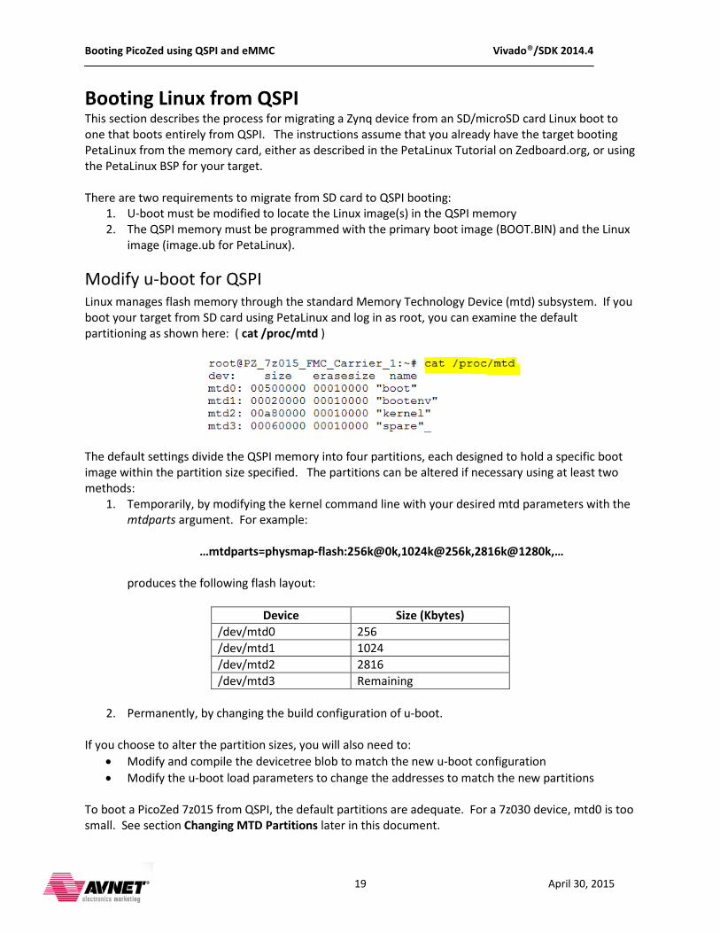
Modify u-boot for QSPI Linux manages flash memory through the standard Memory Technology Device (mtd) subsystem. If you boot your target from SD card using PetaLinux and log in as root, you can examine the default partitioning as shown here: ( cat /proc/mtd )
The default settings divide the QSPI memory into four partitions, each designed to hold a specific boot image within the partition size specified. The partitions can be altered if necessary using at least two methods:
1. Temporarily, by modifying the kernel command line with your desired mtd parameters with the mtdparts argument. For example:
…mtdparts=physmap-flash:256k@0k,1024k@256k,2816k@1280k,… produces the following flash layout:
Device Size (Kbytes) /dev/mtd0 256 /dev/mtd1 1024 /dev/mtd2 2816 /dev/mtd3 Remaining
2. Permanently, by changing the build configuration of u-boot.
If you choose to alter the partition sizes, you will also need to:
• Modify and compile the devicetree blob to match the new u-boot configuration • Modify the u-boot load parameters to change the addresses to match the new partitions
To boot a PicoZed 7z015 from QSPI, the default partitions are adequate. For a 7z030 device, mtd0 is too small. See section Changing MTD Partitions later in this document.
Booting PicoZed using QSPI and eMMC Vivado®/SDK 2014.4
20 April 30, 2015
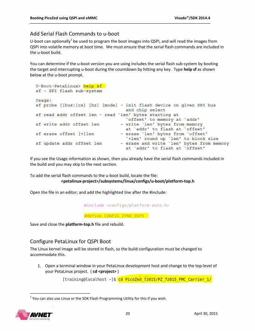
Add Serial Flash Commands to u-boot U-boot can optionally1
be used to program the boot images into QSPI, and will read the images from QSPI into volatile memory at boot time. We must ensure that the serial flash commands are included in the u-boot build.
You can determine if the u-boot version you are using includes the serial flash sub-system by booting the target and interrupting u-boot during the countdown by hitting any key. Type help sf as shown below at the u-boot prompt.
If you see the Usage information as shown, then you already have the serial flash commands included in the build and you may skip to the next section. To add the serial flash commands to the u-boot build, locate the file:
<petalinux-project>/subsystems/linux/configs/u-boot/platform-top.h Open the file in an editor, and add the highlighted line after the #include:
Save and close the platform-top.h file and rebuild.
Configure PetaLinux for QSPI Boot The Linux kernel image will be stored in flash, so the build configuration must be changed to accommodate this.
1. Open a terminal window in your PetaLinux development host and change to the top-level of your PetaLinux project. ( cd <project> )
1 You can also use Linux or the SDK Flash Programming Utility for this if you wish.
Booting PicoZed using QSPI and eMMC Vivado®/SDK 2014.4
21 April 30, 2015
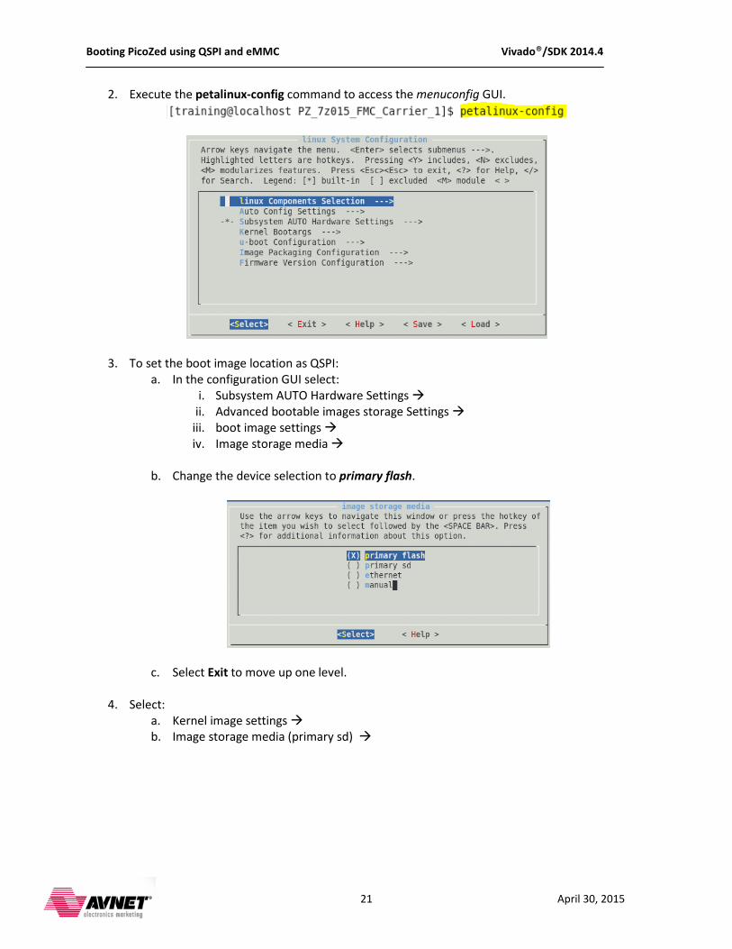
2. Execute the petalinux-config command to access the menuconfig GUI.
3. To set the boot image location as QSPI: a. In the configuration GUI select:
i. Subsystem AUTO Hardware Settings ii. Advanced bootable images storage Settings
iii. boot image settings iv. Image storage media
b. Change the device selection to primary flash.
c. Select Exit to move up one level.
4. Select: a. Kernel image settings b. Image storage media (primary sd)
Booting PicoZed using QSPI and eMMC Vivado®/SDK 2014.4
22 April 30, 2015
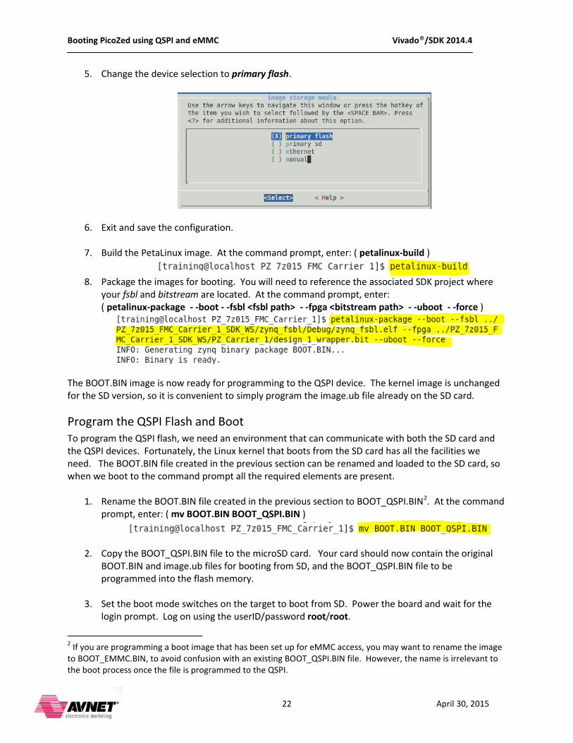
5. Change the device selection to primary flash.
6. Exit and save the configuration.
7. Build the PetaLinux image. At the command prompt, enter: ( petalinux-build )
8. Package the images for booting. You will need to reference the associated SDK project where
your fsbl and bitstream are located. At the command prompt, enter: ( petalinux-package - -boot - -fsbl <fsbl path> - -fpga <bitstream path> - -uboot - -force )
The BOOT.BIN image is now ready for programming to the QSPI device. The kernel image is unchanged for the SD version, so it is convenient to simply program the image.ub file already on the SD card.
Program the QSPI Flash and Boot To program the QSPI flash, we need an environment that can communicate with both the SD card and the QSPI devices. Fortunately, the Linux kernel that boots from the SD card has all the facilities we need. The BOOT.BIN file created in the previous section can be renamed and loaded to the SD card, so when we boot to the command prompt all the required elements are present.
1. Rename the BOOT.BIN file created in the previous section to BOOT_QSPI.BIN2
. At the command prompt, enter: ( mv BOOT.BIN BOOT_QSPI.BIN )
2. Copy the BOOT_QSPI.BIN file to the microSD card. Your card should now contain the original
BOOT.BIN and image.ub files for booting from SD, and the BOOT_QSPI.BIN file to be programmed into the flash memory.
3. Set the boot mode switches on the target to boot from SD. Power the board and wait for the login prompt. Log on using the userID/password root/root.
2 If you are programming a boot image that has been set up for eMMC access, you may want to rename the image to BOOT_EMMC.BIN, to avoid confusion with an existing BOOT_QSPI.BIN file. However, the name is irrelevant to the boot process once the file is programmed to the QSPI.
Booting PicoZed using QSPI and eMMC Vivado®/SDK 2014.4
23 April 30, 2015
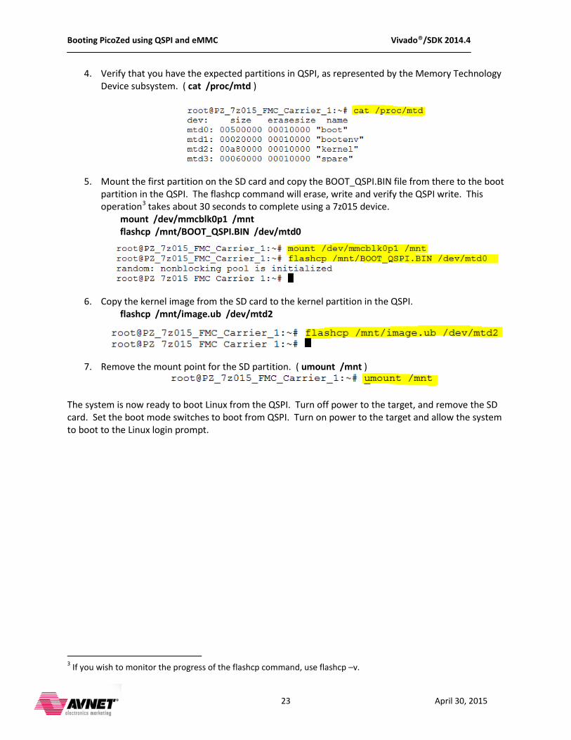
4. Verify that you have the expected partitions in QSPI, as represented by the Memory Technology Device subsystem. ( cat /proc/mtd )
5. Mount the first partition on the SD card and copy the BOOT_QSPI.BIN file from there to the boot partition in the QSPI. The flashcp command will erase, write and verify the QSPI write. This operation3
mount /dev/mmcblk0p1 /mnt takes about 30 seconds to complete using a 7z015 device.
flashcp /mnt/BOOT_QSPI.BIN /dev/mtd0
6. Copy the kernel image from the SD card to the kernel partition in the QSPI. flashcp /mnt/image.ub /dev/mtd2
7. Remove the mount point for the SD partition. ( umount /mnt )
The system is now ready to boot Linux from the QSPI. Turn off power to the target, and remove the SD card. Set the boot mode switches to boot from QSPI. Turn on power to the target and allow the system to boot to the Linux login prompt.
3 If you wish to monitor the progress of the flashcp command, use flashcp –v.
Booting PicoZed using QSPI and eMMC Vivado®/SDK 2014.4
24 April 30, 2015
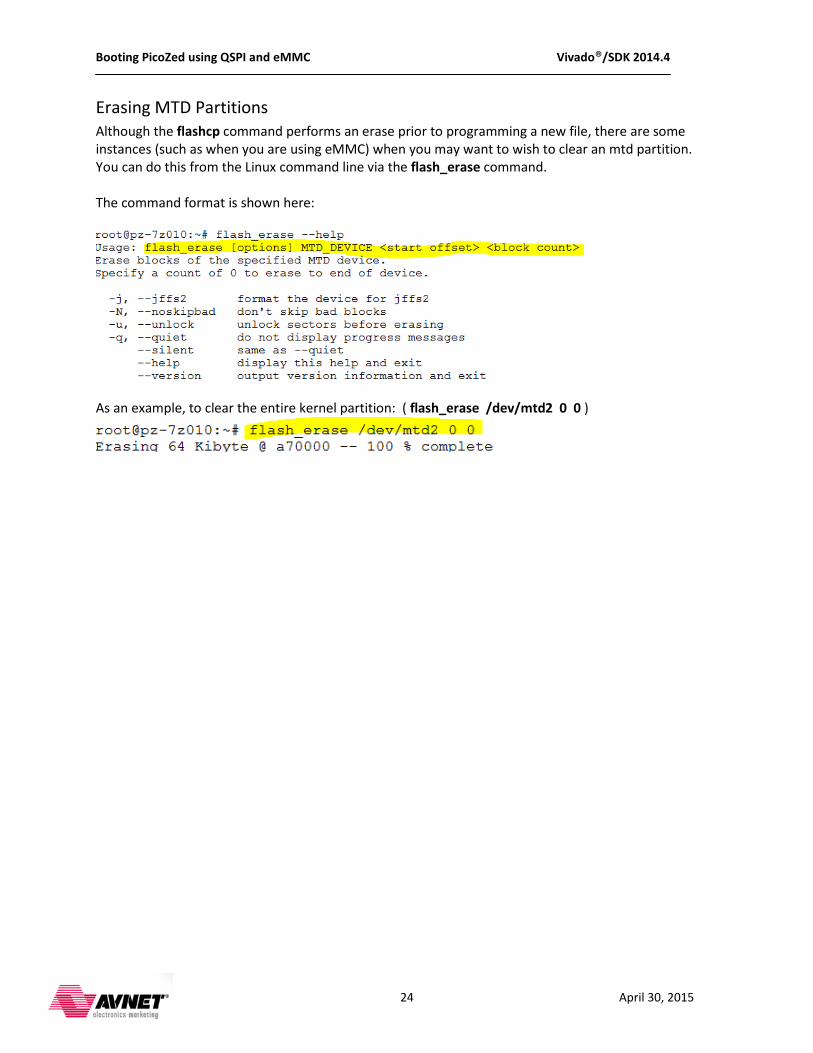
Erasing MTD Partitions Although the flashcp command performs an erase prior to programming a new file, there are some instances (such as when you are using eMMC) when you may want to wish to clear an mtd partition. You can do this from the Linux command line via the flash_erase command. The command format is shown here:
As an example, to clear the entire kernel partition: ( flash_erase /dev/mtd2 0 0 )
Booting PicoZed using QSPI and eMMC Vivado®/SDK 2014.4
25 April 30, 2015
Changing MTD Partitions For larger devices, such as the PicoZed 7z030, the default MTD partition size for the boot image is too small. These steps show how to update the partitions so you can program larger images. The QSPI memory is programmed from Linux, typically booted from the SD card (although Linux could be booted using other means, such as over the network via TFTP). We must modify the MTD partitions in the device tree blob to correspond to the sizes needed to program the QSPI.
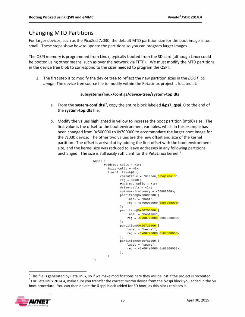
1. The first step is to modify the device tree to reflect the new partition sizes in the BOOT_SD image. The device tree source file to modify within the PetaLinux project is located at:
subsystems/linux/configs/device-tree/system-top.dts
a. From the system-conf.dtsi4
, copy the entire block labeled &ps7_qspi_0 to the end of the system-top.dts file.
b. Modify the values highlighted in yellow to increase the boot partition (mtd0) size. The first value is the offset to the boot environment variables, which in this example has been changed from 0x500000 to 0x700000 to accommodate the larger boot image for the 7z030 device. The other two values are the new offset and size of the kernel partition. The offset is arrived at by adding the first offset with the boot environment size, and the kernel size was reduced to leave addresses in any following partitions unchanged. The size is still easily sufficient for the PetaLinux kernel.5
4 This file is generated by PetaLinux, so if we make modifications here they will be lost if the project is recreated. 5 For PetaLinux 2014.4, make sure you transfer the correct micron device from the &qspi block you added in the SD boot procedure. You can then delete the &qspi block added for SD boot, as this block replaces it.
Booting PicoZed using QSPI and eMMC Vivado®/SDK 2014.4
26 April 30, 2015
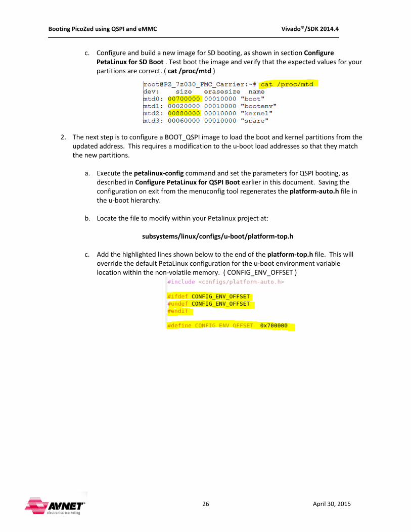
c. Configure and build a new image for SD booting, as shown in section Configure PetaLinux for SD Boot . Test boot the image and verify that the expected values for your partitions are correct. ( cat /proc/mtd )
2. The next step is to configure a BOOT_QSPI image to load the boot and kernel partitions from the updated address. This requires a modification to the u-boot load addresses so that they match the new partitions.
a. Execute the petalinux-config command and set the parameters for QSPI booting, as described in Configure PetaLinux for QSPI Boot earlier in this document. Saving the configuration on exit from the menuconfig tool regenerates the platform-auto.h file in the u-boot hierarchy.
b. Locate the file to modify within your Petalinux project at:
subsystems/linux/configs/u-boot/platform-top.h
c. Add the highlighted lines shown below to the end of the platform-top.h file. This will override the default PetaLinux configuration for the u-boot environment variable location within the non-volatile memory. ( CONFIG_ENV_OFFSET )
Booting PicoZed using QSPI and eMMC Vivado®/SDK 2014.4
27 April 30, 2015
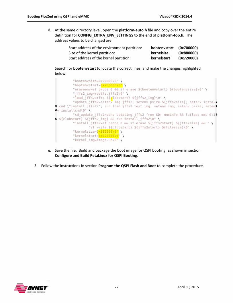
d. At the same directory level, open the platform-auto.h file and copy over the entire definition for CONFIG_EXTRA_ENV_SETTINGS to the end of platform-top.h. The address values to be changed are:
Start address of the environment partition: bootenvstart (0x700000) Size of the kernel partition: kernelsize (0x880000) Start address of the kernel partition: kernelstart (0x720000)
Search for bootenvstart to locate the correct lines, and make the changes highlighted below.
e. Save the file. Build and package the boot image for QSPI booting, as shown in section Configure and Build PetaLinux for QSPI Booting.
3. Follow the instructions in section Program the QSPI Flash and Boot to complete the procedure.
Booting PicoZed using QSPI and eMMC Vivado®/SDK 2014.4
28 April 30, 2015
Prepare the eMMC Memory for Operation The eMMC memory operates very much like a standard SD card, except that there is a built-in controller to implement operational features such as wear-leveling. Before the memory can be used by a software system, it must be partitioned and formatted with a file system, just as would be done for any removable SD storage device. We will use Linux utilities to prepare the eMMC device for use as secondary boot storage.
Boot PetaLinux from SD Card 1. Copy the BOOT.BIN and image.ub files from the PetaLinux BSP to the microSD card.
2. Prepare the hardware and configure the boot mode switches for SD boot, as described in
Setting up the PicoZed and Carrier.
3. Insert the microSD card into the card cage on the underside of the carrier board.
4. Start Tera Term (or equivalent) on your host system. Be sure to connect to the COM port created by the USB-to-UART bridge software from Silicon Labs.
5. Move the power switch to the ON position.
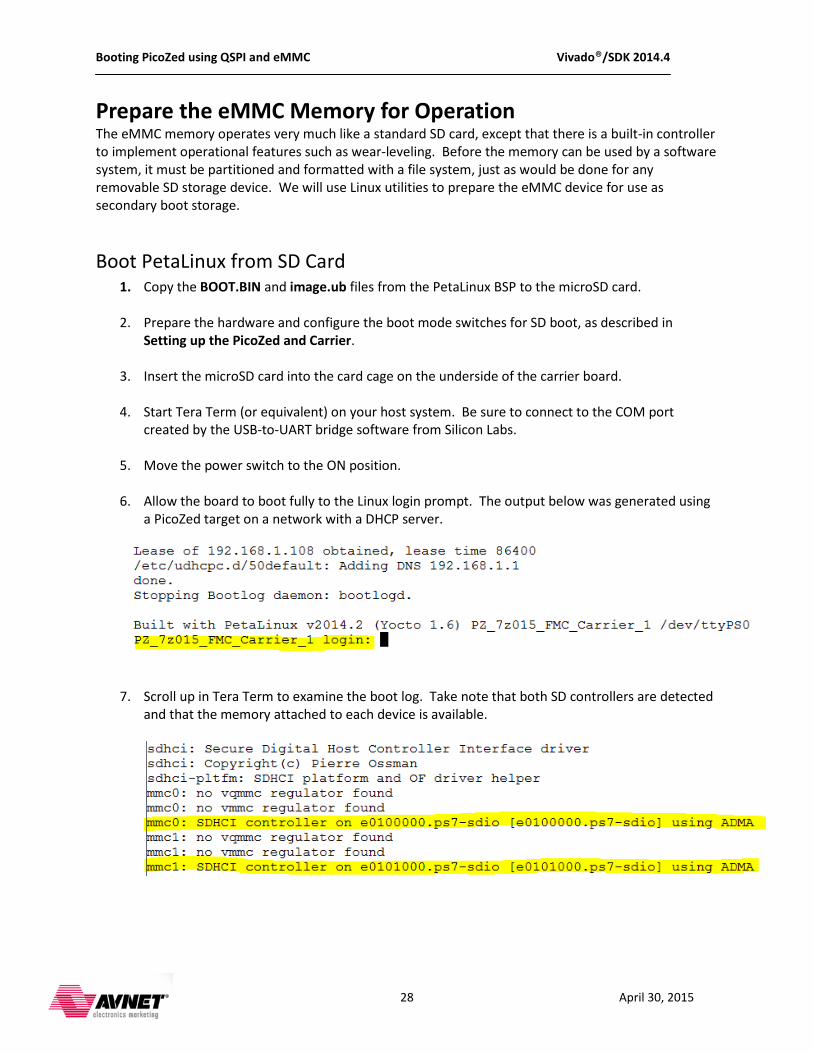
6. Allow the board to boot fully to the Linux login prompt. The output below was generated using
a PicoZed target on a network with a DHCP server.
7. Scroll up in Tera Term to examine the boot log. Take note that both SD controllers are detected
and that the memory attached to each device is available.
Booting PicoZed using QSPI and eMMC Vivado®/SDK 2014.4
29 April 30, 2015
8. Log in to the Linux environment with userid/pw root/root.
Partition and Format the eMMC
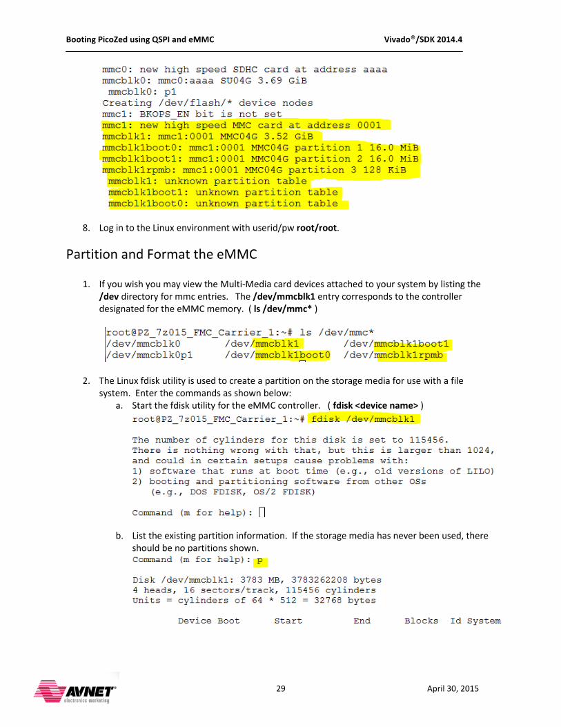
1. If you wish you may view the Multi-Media card devices attached to your system by listing the /dev directory for mmc entries. The /dev/mmcblk1 entry corresponds to the controller designated for the eMMC memory. ( ls /dev/mmc* )
2. The Linux fdisk utility is used to create a partition on the storage media for use with a file system. Enter the commands as shown below:
a. Start the fdisk utility for the eMMC controller. ( fdisk <device name> )
b. List the existing partition information. If the storage media has never been used, there should be no partitions shown.
Booting PicoZed using QSPI and eMMC Vivado®/SDK 2014.4
30 April 30, 2015
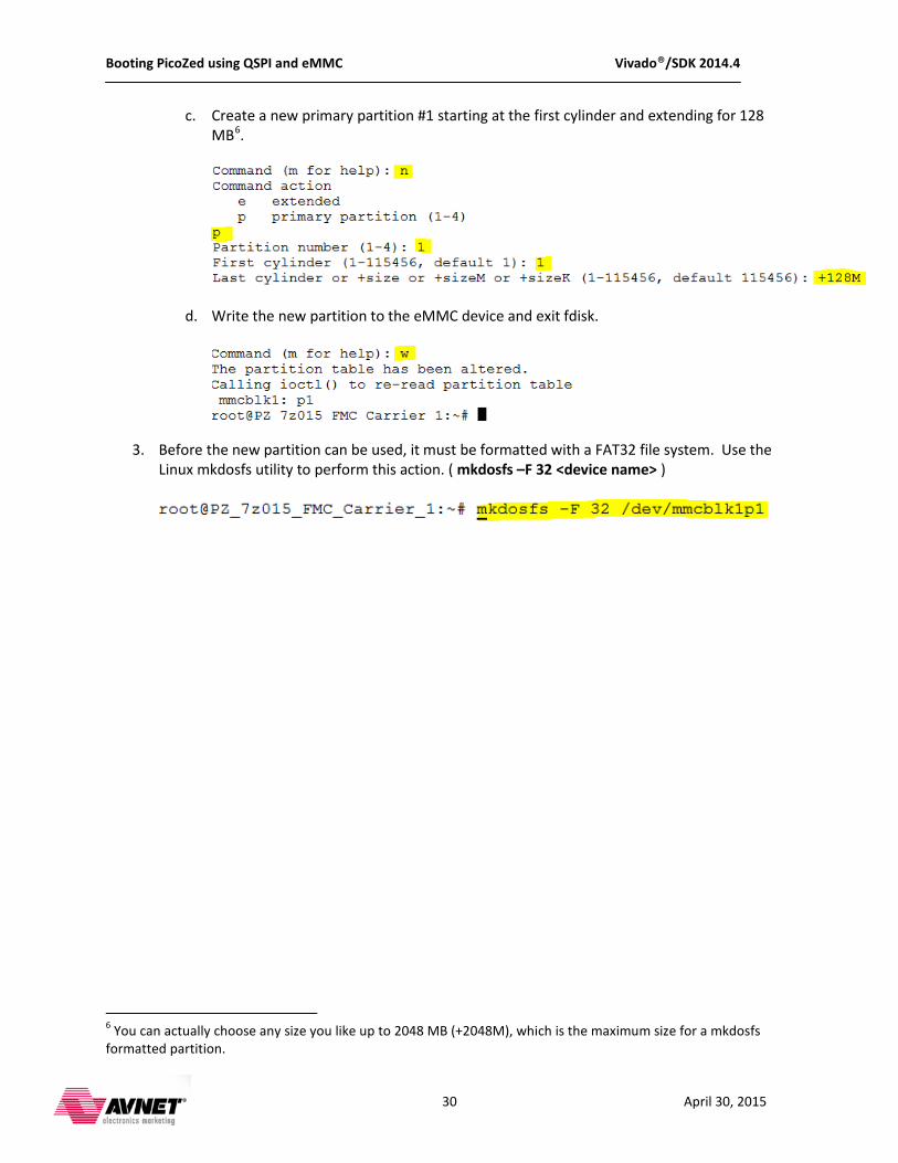
c. Create a new primary partition #1 starting at the first cylinder and extending for 128 MB6
.
d. Write the new partition to the eMMC device and exit fdisk.
3. Before the new partition can be used, it must be formatted with a FAT32 file system. Use the Linux mkdosfs utility to perform this action. ( mkdosfs –F 32 <device name> )
6 You can actually choose any size you like up to 2048 MB (+2048M), which is the maximum size for a mkdosfs formatted partition.

Booting PicoZed using QSPI and eMMC Vivado®/SDK 2014.4
31 April 30, 2015
Copy Secondary Boot Files to eMMC
Mount the partitions for the SD card and eMMC and copy the image.ub file from SD to eMMC.
1. Create a temporary directory to mount the SD card and then create a mount point at this new location. You may list the mount point to validate that it does indeed represent the SD card (the files you see will be those on your card, not the listing shown here).
mkdir /temp mount /dev/mmcblk0p1 /temp ls /temp
2. Create a mount point for the eMMC partition and copy the image.ub file from the SD card. You may list the new mount point to verify that you have copied the file successfully to the eMMC device.
mount /dev/mmcblk1p1 /mnt cp /temp/image.ub /mnt/. ls /mnt
3. Release the mount points for the SD and eMMC devices. umount /temp umount /mnt
The eMMC device is now ready for operation and contains the PetaLinux kernel image that will be loaded by the second stage boot loader u-boot.

Booting PicoZed using QSPI and eMMC Vivado®/SDK 2014.4
32 April 30, 2015
Configure and Build PetaLinux to Boot from QSPI and eMMC With the kernel image in the eMMC, the next step is to reconfigure u-boot to load the image from eMMC instead of the SD card. At the same time we can modify the u-boot configuration in the PetaLinux tool chain to allow u-boot (within the primary boot image BOOT.BIN) to be stored in QSPI. The PetaLinux boot configuration should have the following settings:
• Boot image configured to boot from primary flash (QSPI) • Kernel image configured to boot from primary sd (eMMC) • Primary SD/SDIO configured to use ps7_sd_1 (eMMC controller)
1. On your PetaLinux development host, change to the top level of your PetaLinux project.
2. Start the configuration tool. ( petalinux-config )
3. To set the boot image location as QSPI: a. In the configuration GUI select:
i. Subsystem AUTO Hardware Settings ii. Advanced bootable images storage Settings
iii. boot image settings iv. Image storage media
b. Change the device selection to primary flash.
c. Select Exit to move up one level.
Booting PicoZed using QSPI and eMMC Vivado®/SDK 2014.4
33 April 30, 2015
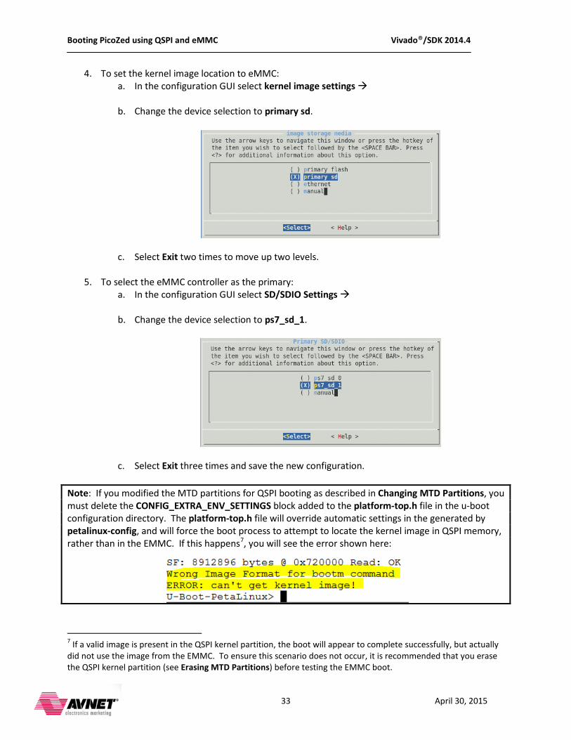
4. To set the kernel image location to eMMC: a. In the configuration GUI select kernel image settings
b. Change the device selection to primary sd.
c. Select Exit two times to move up two levels.
5. To select the eMMC controller as the primary: a. In the configuration GUI select SD/SDIO Settings
b. Change the device selection to ps7_sd_1.
c. Select Exit three times and save the new configuration.
Note: If you modified the MTD partitions for QSPI booting as described in Changing MTD Partitions, you must delete the CONFIG_EXTRA_ENV_SETTINGS block added to the platform-top.h file in the u-boot configuration directory. The platform-top.h file will override automatic settings in the generated by petalinux-config, and will force the boot process to attempt to locate the kernel image in QSPI memory, rather than in the EMMC. If this happens7
, you will see the error shown here:
7 If a valid image is present in the QSPI kernel partition, the boot will appear to complete successfully, but actually did not use the image from the EMMC. To ensure this scenario does not occur, it is recommended that you erase the QSPI kernel partition (see Erasing MTD Partitions) before testing the EMMC boot.
Booting PicoZed using QSPI and eMMC Vivado®/SDK 2014.4
34 April 30, 2015
6. Build the PetaLinux image. At the command prompt, enter: ( petalinux-build )
7. Package the images for booting. You will need to reference the associated SDK project where your fsbl and bitstream are located. At the command prompt, enter:
petalinux-package - - boot - - fsbl <path to elf> - - fpga < path to bitstream> - - uboot - - force
The BOOT.BIN image is now ready for programming to the QSPI device. See the instructions in section Program QSPI Flash and Boot. When you boot the target with the mode switches set for QSPI, it will load the boot image from QSPI and u-boot will load the kernel image from eMMC.
Moving the Bitstream to eMMC Zynq devices are hardwired in BOOTROM code to boot only from NAND, NOR, SD or QSPI persistent memory devices. However, it is possible to reduce the size of the primary boot image by moving the bitstream, normally the largest component by far, to secondary persistent storage. In this configuration, the primary boot image consists only of the first and second stage bootloaders, to create an image that is often less than 500K bytes. The second stage loader, u-boot in this case, is responsible for loading the Programmable Logic in the device via PCAP. The procedure can be demonstrated using a PicoZed module and carrier combination, where the boot image is stored in QSPI, and the bitstream and PetaLinux image is stored in eMMC. This example assumes that you have successfully completed the preceding sections and have your device booting from QSPI, with a bitstream contained inside the primary boot image, and the PetaLinux image.ub file stored in eMMC. The following tasks are required to move the bitstream to eMMC.
1. Modify the u-boot configuration to add bitstream loading from eMMC memory.
2. Use the PetaLinux toolchain to create a boot image with only the first stage loader and u-boot.
3. Use the write_cfgmem TCL command in Vivado to modify the bitstream by performing byte-swapping, required to load via the PCAP interface.
4. Write the new binary file to the eMMC and boot the target from QSPI/eMMC.

Booting PicoZed using QSPI and eMMC Vivado®/SDK 2014.4
35 April 30, 2015
Modify and build U-boot Ensure the PetaLinux configuration is set to boot as described in Configure and Build PetaLinux to Boot from QSPI and eMMC. In your PetaLinux project hierarchy, locate the u-boot configuration directory at:
subsystems/linux/configs/u-boot/
Open the platform-auto.h file and copy the entire CONFIG_EXTRA_ENV_SETTINGS block to the platform-top.h file. Modify the platform-top.h file as follows8
1. Add environment variable loadbit_addr to specify a RAM location to copy the bitstream from eMMC.
:
2. Add environment variable bitstream_image to specify the name of the byte-swapped bitstream file.
3. Add environment variable mmc_loadbit_fat to program a sequence of u-boot commands to copy the bitstream_image file to RAM, and subsequently write the image to the Programmable Logic.
4. Modify the sdboot environment variable to invoke the mmc_loadbit_fat commands in addition to copying the kernel image from eMMC and booting the Linux kernel.
5. Modify the default_bootcmd environment variable to invoke the sdboot sequence when control is passed from the first stage loader to u-boot.
8 There are many ways to modify the u-boot configuration to achieve the desired boot sequence. This section describes one implementation.
Booting PicoZed using QSPI and eMMC Vivado®/SDK 2014.4
36 April 30, 2015
Save the changes to platform-top.h, return to the top level of your PetaLinux project and build u-boot from the command line (petalinux-build –c u-boot).
Create the Boot Image From the top-level directory of your PetaLinux project, you can use the petalinux-package command as usual to create the boot image. All you need to do is omit the - -fpga option to exclude it.
petalinux-package - -boot - - fsbl pre-built/linux/images/zynq_fsbl.elf - -uboot - - force
As seen here, the generated BOOT.BIN is less than 400 KB.
Follow the steps in Program the QSPI Flash and Boot to write the new boot image to QSPI on your target. Modify the Bitstream File The standard bitstream file format must be modified to allow u-boot to load it into the programmable logic on the Zynq device via PCAP. In the past, ISE included a promgen tool to perform this operation. Vivado Design Suite implements the same functionality as a TCL command called write_cfgmem.
Locate your chosen bitstream or use the one included in the BSP at:
pre-bult/linux/implementation/download.bit
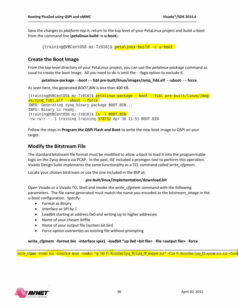
Open Vivado or a Vivado TCL Shell and invoke the write_cfgmem command with the following parameters. The file name generated must match the name you encoded as the bitstream_image in the u-boot configuration. Specify:
• Format as Binary • Interface as SPI by 1 • Loadbit starting at address 0x0 and writing up to higher addresses • Name of your chosen bitfile • Name of your output file (system.bit.bin) • Force option overwrites an existing file without prompting
write_cfgmem -format bin -interface spix1 -loadbit “up 0x0 <bit file> -file <output file> -force
Booting PicoZed using QSPI and eMMC Vivado®/SDK 2014.4
37 April 30, 2015
Write the Modified Image to eMMC9
Boot Linux as normal on the target from an SD card image, and follow the steps in
and Boot Copy Secondary Boot
Files to eMMC to write the binary image to eMMC. Configure the mode switches to boot from QSPI, remove the microSD card and power the target.
Appendix I: Installation of USB UART Driver Many of the Avnet evaluation boards are equipped with the Silicon Labs CP2102 USB-to-UART Bridge IC. This connects a PC’s USB port to the evaluation board and looks like a UART to the PC. A virtual COM port will be created on the PC by means of a Silicon Labs CP2102 USB-to-UART bridge driver. To install the Silicon Labs drivers follow the instructions listed below.
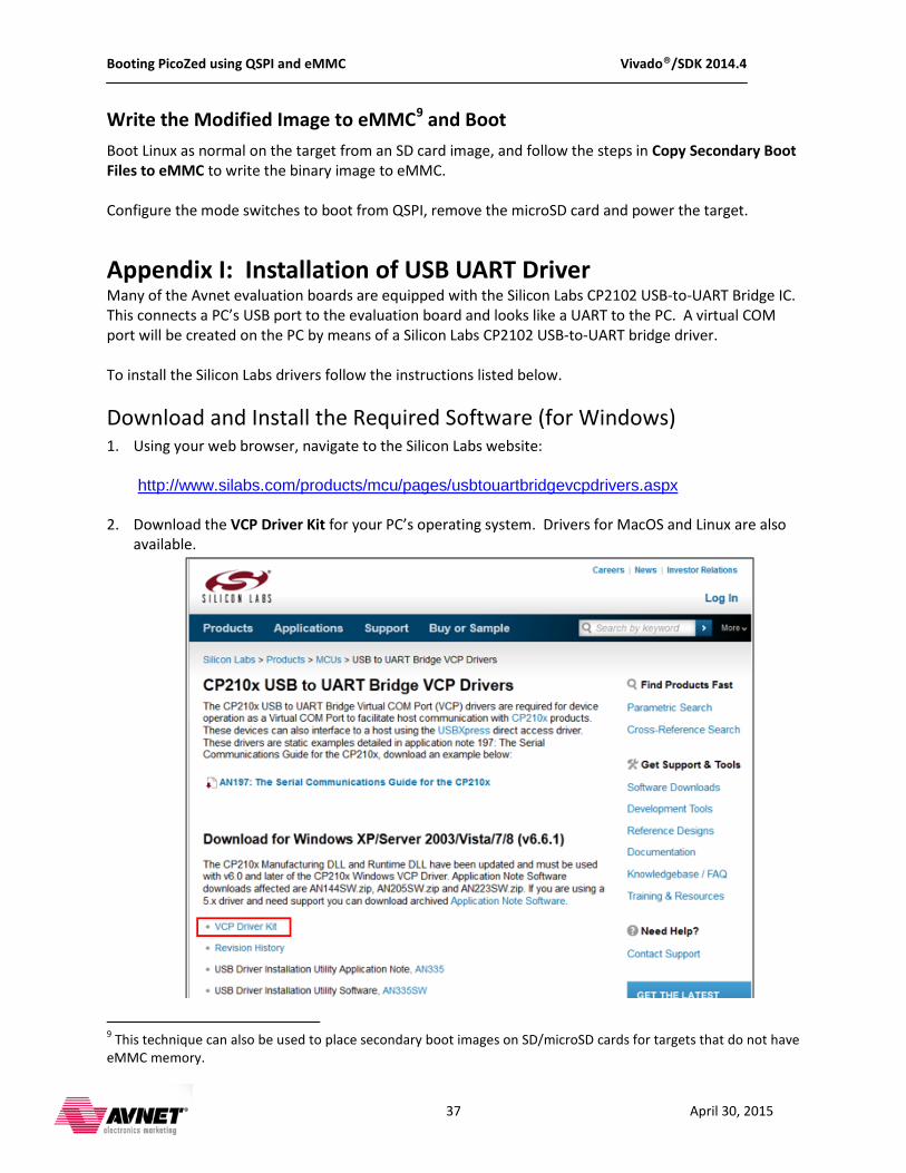
Download and Install the Required Software (for Windows) 1. Using your web browser, navigate to the Silicon Labs website:
http://www.silabs.com/products/mcu/pages/usbtouartbridgevcpdrivers.aspx
2. Download the VCP Driver Kit for your PC’s operating system. Drivers for MacOS and Linux are also
available.
9 This technique can also be used to place secondary boot images on SD/microSD cards for targets that do not have eMMC memory.
Booting PicoZed using QSPI and eMMC Vivado®/SDK 2014.4
38 April 30, 2015
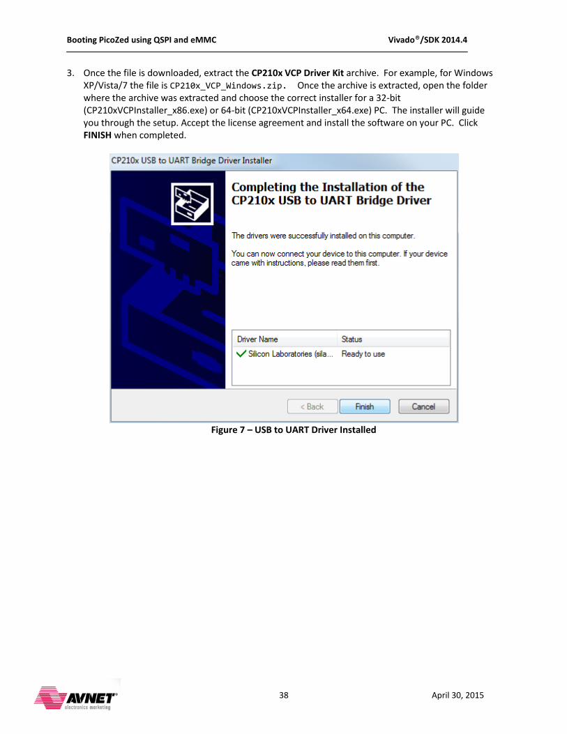
3. Once the file is downloaded, extract the CP210x VCP Driver Kit archive. For example, for Windows XP/Vista/7 the file is CP210x_VCP_Windows.zip. Once the archive is extracted, open the folder where the archive was extracted and choose the correct installer for a 32-bit (CP210xVCPInstaller_x86.exe) or 64-bit (CP210xVCPInstaller_x64.exe) PC. The installer will guide you through the setup. Accept the license agreement and install the software on your PC. Click FINISH when completed.
Figure 7 – USB to UART Driver Installed
Booting PicoZed using QSPI and eMMC Vivado®/SDK 2014.4
39 April 30, 2015
Determining the Virtual COM Port (on Windows) Now you can connect the evaluation board’s USB-to-UART port to one of the USB ports on your PC. The new hardware detection will pop up and enumeration of the driver will be started. Once finished a virtual COMx port is created and you are ready to setup a connection using Windows HyperTerminal or comparable serial terminal emulation utility. Follow these instructions to determine the COMx port assigned to the USB-to-UART bridge:
1. Attach power to your target, and connect a USB A-micro B cable between the UART port of the board and an open USB port on your host computer. Set the board power switch to the ON position.
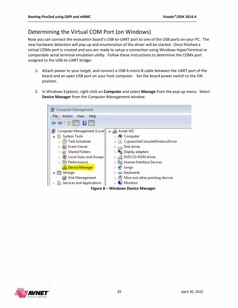
2. In Windows Explorer, right-click on Computer and select Manage from the pop-up menu. Select Device Manager from the Computer Management window.
Figure 8 – Windows Device Manager
Booting PicoZed using QSPI and eMMC Vivado®/SDK 2014.4
40 April 30, 2015
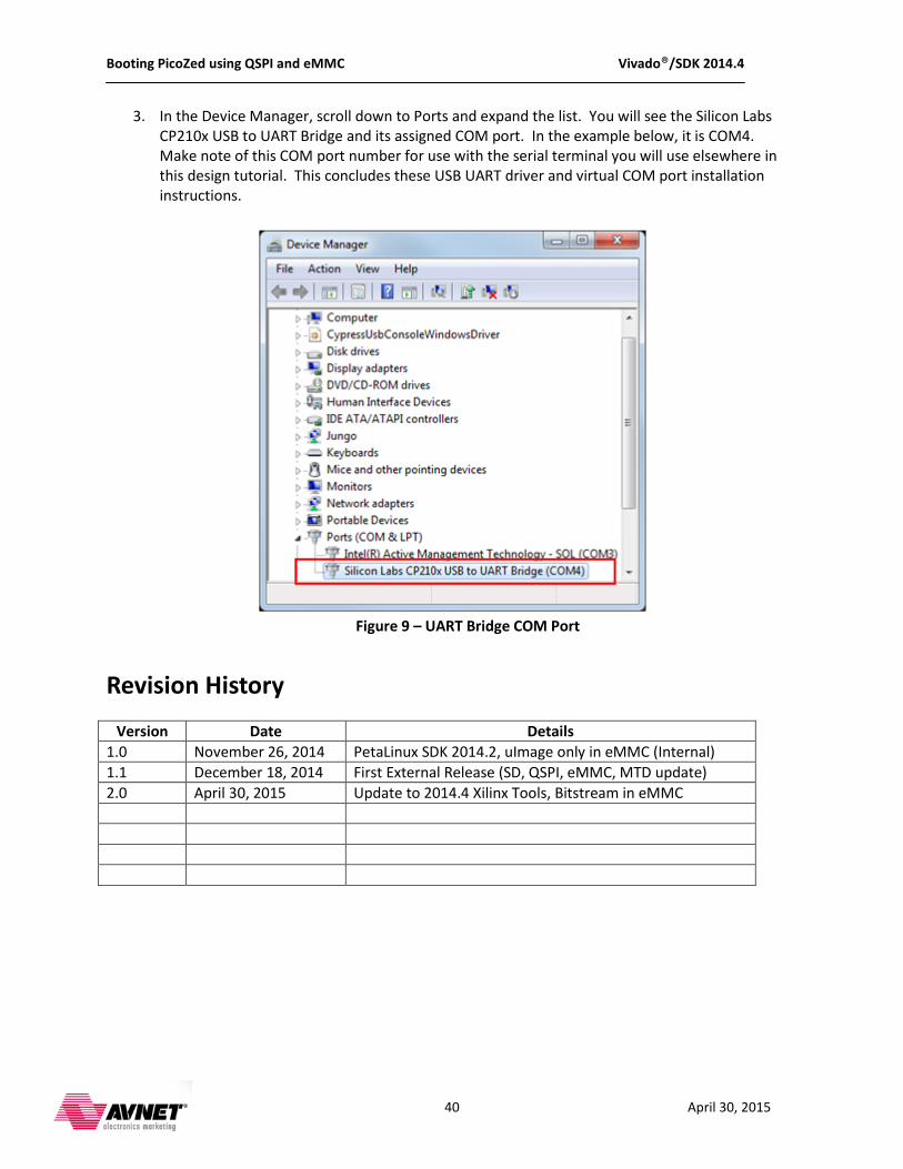
3. In the Device Manager, scroll down to Ports and expand the list. You will see the Silicon Labs CP210x USB to UART Bridge and its assigned COM port. In the example below, it is COM4. Make note of this COM port number for use with the serial terminal you will use elsewhere in this design tutorial. This concludes these USB UART driver and virtual COM port installation instructions.
Figure 9 – UART Bridge COM Port
Revision History
Version Date Details 1.0 November 26, 2014 PetaLinux SDK 2014.2, uImage only in eMMC (Internal) 1.1 December 18, 2014 First External Release (SD, QSPI, eMMC, MTD update) 2.0 April 30, 2015 Update to 2014.4 Xilinx Tools, Bitstream in eMMC