Embed Size (px)
Citation preview
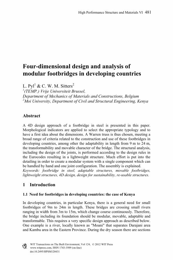
Four-dimensional design and analysis of modular footbridges in developing countries
L. Pyl1 & C. W. M. Sitters2 1(TEMP.) Vrije Universiteit Brussel, Department of Mechanics of Materials and Constructions, Belgium 2Moi University, Department of Civil and Structural Engineering, Kenya
Abstract
A 4D design approach of a footbridge in steel is presented in this paper. Morphological indicators are applied to select the appropriate typology and to have a first idea about the dimensions. A Warren truss is thus chosen, meeting a broad range of criteria related to the construction and use of these footbridges in developing countries, among other the adaptability in length from 9 m to 24 m, the transformability and movable character of the bridge. The structural analysis, including the design of the joints, is performed according to the design rules in the Eurocodes resulting in a lightweight structure. Much effort is put into the detailing in order to create a modular system with a single component which can be handled by hand and one joint configuration. The assembly is explained. Keywords: footbridge in steel, adaptable structures, movable footbridges, lightweight structures, 4D design, design for sustainability, re-usable structures.
1 Introduction
1.1 Need for footbridges in developing countries: the case of Kenya
In developing countries, in particular Kenya, there is a general need for small footbridges of 9m to 24m in length. These bridges are crossing small rivers ranging in width from 3m to 15m, which change course continuously. Therefore, the bridge including its foundation should be modular, movable, adaptable and transformable. This requires a very specific design approach as described below. One example is a river, locally known as "Moani" that separates Darajani area and Kambu area in the Eastern Province. During the dry season there are sections
High Performance Structure and Materials VI 481
www.witpress.com, ISSN 1743-3509 (on-line) WIT Transactions on The Built Environment, Vol 124, © 201 WIT Press2
doi:10.2495/HPSM120 143
in the river people can wade through but that become impassable during heavy rainfall. At such times, the community on one side of the river is cut off from commuting and from access to transport means to health facilities, markets, schools and business in general. As usual old people, women and children suffer most under such conditions. Unfortunately such are also the high seasons for malaria and other infections. This is also the low season of food availability. It so happens that some households literally run into famine situation. For the last 20 years, there has been a struggle to put up pedestrian bridges using poles and timber. These do not last long and a lot of difficulty is experienced when using the bridge. Another example causing similar problems is the river "Awach" that flows from the Kisii highlands of Nyanza Province of Kenya to the world's third largest fresh water lake, the Lake Victoria. The river separates Kodhoch and Landa areas along its meandering course. As part of the collaboration between Moi University and Vrije Universiteit Brussels (VUB), student projects were carried out on the design of footbridges crossing the Awach. Just recently a bridge has been constructed.
1.2 Adoption of Eurocodes in Kenya
A complicating factor is that the UK has changed to Eurocodes. Consequently, British Standards that are used in Kenya in the design of steel structures will not be updated anymore and will become obsolete in due time. It is recognised by the Kenya Bureau of Standards (KEBS) that there is an urgent need to adopt/adapt the Eurocodes in general and Eurocode 3 for steel in particular. As part of a cooperation program between VUB and Moi University, training of bachelor and master students in civil and structural engineering at Moi and Kenyan engineers in industry and public institutions in using Eurocodes has been put in place. Therefore, in the design of footbridges Eurocode 3 will be used.
1.3 The use of 4D design techniques and morphological indicators in the conceptual design phase
Research on the conceptual design and analysis of footbridges is performed. Re-usable, transformable and adaptable structures require a 4D design approach, with the aspect time considered as the fourth dimension. A design as polyvalent, transformable, sectional and re-usable as possible is needed both for environmental issues as well as for local labour habits. A multi-configurational component is designed, applicable for other structures. Sustainability will be a key aspect in the design of the structure. The use of material has to be limited. Therefore, morphological indicators are used in the conceptual design phase. A demountable system using components with limited volume and/or weight should be considered to facilitate transportation to remote areas. The mounting of the bridge on site, enhancing labour for the local workforce, has to be unambiguous, thus requiring multipurpose standard elements. These elements should be light enough to be handled by hand, so that advanced hoisting equipment is avoided. Sub-assemblies galvanized or coated, perforated and welded in the workshop and hinged connections, for easy assembly on site and
482 High Performance Structure and Materials VI
www.witpress.com, ISSN 1743-3509 (on-line) WIT Transactions on The Built Environment, Vol 124, © 201 WIT Press2
that are constructed such that the removal of a connector is hampered or prohibited, are the best choices. Welding activities on site will be limited (just to secure bolts and pins) because they are less practical than dry connections. A design will be presented that meets most of the above listed criteria.
2 Design procedures for the foundation and the footbridge
2.1 Design conditions
The soil conditions of the underground where the foundation of the bridge is planned on the river bank show a wide variability throughout the country. These can be solid or weathered rock, combination of soil with boulders and often deep red lateritic soil. For the foundation, a modular and movable system will be chosen, that is made of interlocking concrete blocks [1, 2]. These foundations need to be constructed on a smooth horizontal underground. For soils that can be dug out this can be achieved easily. A foundation depth of 1 m seems sufficient. The minimum foundation area required depends on the bearing capacity of the soil, which can be measured in situ. For the harder undergrounds, no major problems with the bearing capacity are expected. These undergrounds should be cleaned, especially heavy weathered rock, and a layer of concrete applied to have a smooth horizontal foundation area. The height difference between the foundation areas on the two riverbanks should be a whole number times the thickness of the foundation elements. In this way, the foundations can be built up such that the bridge is horizontal. On top of the foundations, steel bridge supports need to be placed that interlocks with the foundation, so that none of the foundation blocks can be removed. At one side the bridge, the support is pinned while on the other side there is a sliding or rolling connection. In this paper no further attention will be paid to the design of the foundation and the bridge support system. Naturally, most small rivers in developing countries, in particular Kenya, are situated in rural areas and can only be assessed by dirt roads or even footpaths. For that reason all components of the bridge should be transported by a small lorry or pick-up car. The elements should not exceed 3 to 4m in length. Further, the elements should be lightweight so that they can be carried to site manually if the means of motorised transport cannot reach the river. As mentioned, the streams tend to change their course in due time, the bridge including the foundation should be deconstructable so that it can be built up again at another spot along the river. This modular approach based on the use of single elements, easy to handle, is taken as a principal requirement in the conceptual design.
2.2 Structural optimisation
In the conceptual design stage, morphological indicators (MI) are used for the choice of typology. Based on the geometrical properties of a structure, the efficiency both in strength, stiffness and stability is evaluated using morphological indicators.
High Performance Structure and Materials VI 483
www.witpress.com, ISSN 1743-3509 (on-line) WIT Transactions on The Built Environment, Vol 124, © 201 WIT Press2
Two main groups of indicators can be distinguished: geometrical indicators and performance indicators. The geometrical indicators can be the geometrical slenderness (global for the structure) and the form factors (local for the components). The geometrical slenderness (L/H) is defined as the ratio of length L and height H of the smallest window in which the structure (i.c. the footbridge) can be inscribed. The form factors q = I/², s = /h² and Z = 1/16sq are dimensionless numbers expressing the distribution of material with respect to the centre of gravity of the section and depending on the geometry of the cross-section (moment of inertia I, area , height h, width b, thickness e). The first performance indicators, elaborated by Samyn [3] are the volume indicator (W) and the indicator of displacement (). These dimensionless numbers only depend (in the original formulation) on the geometrical slenderness. In his thesis, Samyn set the limits to statically determinate two-dimensional structures, loaded with a uniformly distributed vertical load or a vertical moving point load. He assumed a fully stressed design, which means that under the considered load combination, all the elements work at the ultimate stress level . Second order effects (buckling, P- effects) are not considered by Samyn. Latteur [4] therefore developed in his doctoral thesis the indicator of buckling . This indicator considers the ‘local’ buckling of all elements in the structure and thus not the global buckling. A fourth indicator, the indicator of self weight , is a measure of the portion of the self weight of the structure in the allowable stress and can be used to determine the limit span. Van Steirteghem showed that the influence of buckling overrules the influence of self weight, especially for structures with a small structural index F/L², thus a large span/load ratio [5]. Therefore, the volume indicator W of Samyn always yields a minimum value as a fully stressed design (fsd) is assumed but cautiousness is required for compression members. Ad hoc measures to reduce the buckling length might be necessary. Van Steirteghem also added a major contribution to the theory of morphological indicators in the field of dynamics, which can become dominant in large span structures. Verbeeck studied the optimisation of structures using MI in combination with genetic algorithms [6]. The joint research work on morphological indicators of a group founded in 2000 by Samyn and De Wilde, is summarized in a book by Samyn [7]. It should be emphasized though that the elements subjected to tension are assumed to have sufficient length to be able to disregard the volume of the connections. In theory, the transmission of forces between elements in compression does not consume any material. Pinned connections are assumed. Bending moments in elements due to bending rigidities in imperfectly pinned connections (or friction) can be taken into consideration using a method developed by Latteur [4]. Since the morphological indicators are used here in the conceptual design stage for the choice of the typology of the footbridge, assuming pinned connections and disregarding the volume of the connections will yield acceptable results according to the authors. Including this volume will be unfavourable for the volume indicator but more realistic.
484 High Performance Structure and Materials VI
www.witpress.com, ISSN 1743-3509 (on-line) WIT Transactions on The Built Environment, Vol 124, © 201 WIT Press2
Amongst the numerous typologies available for footbridges (truss bridges, beam bridges, (tied) arch bridges, cable-stayed bridges), the truss bridge is chosen in this work. A design consuming the least possible non-renewable material is considered as being the most adequate from a point of view of sustainability [7]. Although it might require more labour (due to the complexity of the connections for example) the least material is the most appropriate criterion, because it is independent of the difference in labour cost between industrialised countries and developing countries. Furthermore, labour is considered being renewable (and commendable!) whereas material is non-renewable and scarce, especially in developing countries. Latteur et al. [8] compared the self weight and the rigidity of classical trusses as Warren, Pratt or Howe trusses, subjected to fixed or stochastic loads using MI. This approach allows to reduce the amount of parameters in the optimisation process and to produce universal efficiency curves related to a family of trusses. From those curves showing the volume indicator W or the indicator of displacement as a function of the geometrical slenderness L/H for a certain value of the indicator of buckling allows to optimise the weight or the stiffness of trusses, irrespective of material, type of sections, span or value of the loads. Latteur showed inferiority of the Howe truss both in volume indicators and indicators of displacement. The Warren truss has the best performance both in strength and stiffness although in tight competition with the Pratt truss for the latter.
2.3 More details on the 4D design procedure
2.3.1 Conceptual design stage Buckling sensitivity can be reduced using the highest possible form factor q as the indicator of buckling is inversely proportional to the root of the form factor. A lower bound of the thickness to width ratio t/c (Table 1) is imposed for circular and square tubes to avoid local buckling in the compression parts [9] depending on the steel grade. The wall thickness of hollow sections should not be less than 2.5mm and for hollow section chord it should not be greater than 25 mm [10], though more applicable to welded joints. Based on these criteria, the form factor q varies between 0.11 and 1.80 for commercially available circular (CHS), between 0.32 and 2.77 for rectangular (RHS), between 0.17 and 2.06 for square hollow sections (SHS) and between 1.37 and 5.22 for IPE sections. As the truss members in compression predominantly suffer from out-of-plane buckling, SHS are preferred. To ascertain the manual lifting of the elements, assembly on site of single truss members is required. With a length of 3 meter and an average weight between 15 and 20kg per unit length, two persons can handle a single element. Sub-assembly of panels is thus impossible without special hoisting equipment. In the conceptual design stage, a simply supported Warren truss with a maximum span equal to L = 24 m is investigated using morphological indicators. In order that one single type of connection elements is appropriate within the truss, equilateral triangles with angles = 60° are used. The overall height of the
High Performance Structure and Materials VI 485
www.witpress.com, ISSN 1743-3509 (on-line) WIT Transactions on The Built Environment, Vol 124, © 201 WIT Press2
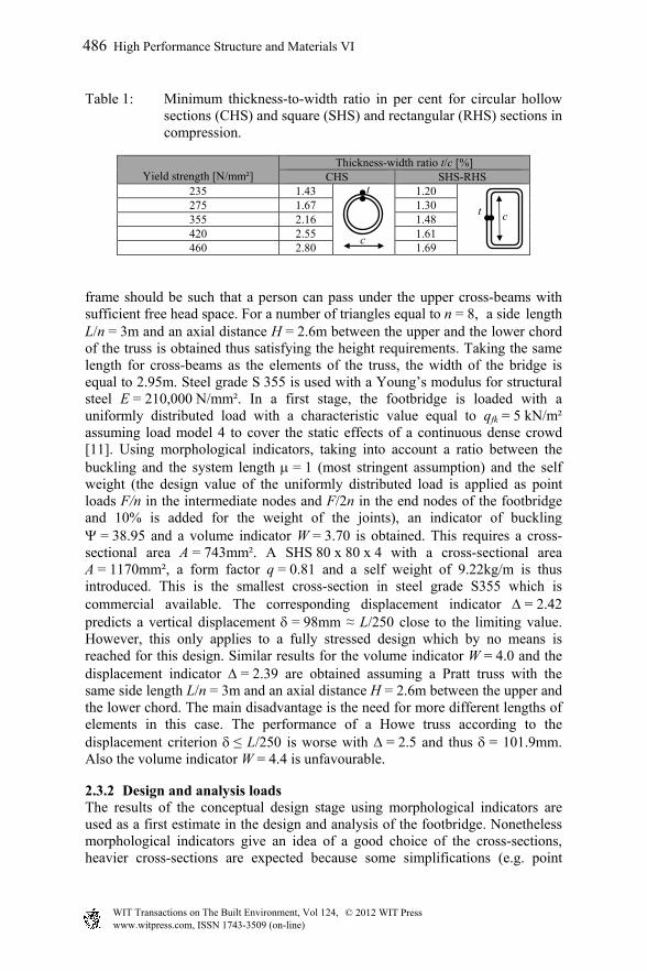
Table 1: Minimum thickness-to-width ratio in per cent for circular hollow sections (CHS) and square (SHS) and rectangular (RHS) sections in compression.
Yield strength [N/mm²]
Thickness-width ratio t/c [%] CHS SHS-RHS
235 1.43 1.20 275 1.67 1.30 355 2.16 1.48 420 2.55 1.61 460 2.80 1.69
frame should be such that a person can pass under the upper cross-beams with sufficient free head space. For a number of triangles equal to n = 8, a side length L/n = 3m and an axial distance H = 2.6m between the upper and the lower chord of the truss is obtained thus satisfying the height requirements. Taking the same length for cross-beams as the elements of the truss, the width of the bridge is equal to 2.95m. Steel grade S 355 is used with a Young’s modulus for structural steel E = 210,000 N/mm². In a first stage, the footbridge is loaded with a uniformly distributed load with a characteristic value equal to qfk = 5 kN/m² assuming load model 4 to cover the static effects of a continuous dense crowd [11]. Using morphological indicators, taking into account a ratio between the buckling and the system length = 1 (most stringent assumption) and the self weight (the design value of the uniformly distributed load is applied as point loads F/n in the intermediate nodes and F/2n in the end nodes of the footbridge and 10% is added for the weight of the joints), an indicator of buckling = 38.95 and a volume indicator W = 3.70 is obtained. This requires a cross-sectional area A = 743mm². A SHS 80 x 80 x 4 with a cross-sectional area A = 1170mm², a form factor q = 0.81 and a self weight of 9.22kg/m is thus introduced. This is the smallest cross-section in steel grade S355 which is commercial available. The corresponding displacement indicator = 2.42 predicts a vertical displacement = 98mm ≈ L/250 close to the limiting value. However, this only applies to a fully stressed design which by no means is reached for this design. Similar results for the volume indicator W = 4.0 and the displacement indicator = 2.39 are obtained assuming a Pratt truss with the same side length L/n = 3m and an axial distance H = 2.6m between the upper and the lower chord. The main disadvantage is the need for more different lengths of elements in this case. The performance of a Howe truss according to the displacement criterion ≤ L/250 is worse with = 2.5 and thus = 101.9mm. Also the volume indicator W = 4.4 is unfavourable.
2.3.2 Design and analysis loads The results of the conceptual design stage using morphological indicators are used as a first estimate in the design and analysis of the footbridge. Nonetheless morphological indicators give an idea of a good choice of the cross-sections, heavier cross-sections are expected because some simplifications (e.g. point
t
c
t c
486 High Performance Structure and Materials VI
www.witpress.com, ISSN 1743-3509 (on-line) WIT Transactions on The Built Environment, Vol 124, © 201 WIT Press2
loads in nodes) are introduced in the conceptual design using MI. The self weight of the elements is automatically taken into account. A uniformly distributed load with a characteristic value qfk = 5 kN/m² is applied [11]. This load covers the static effects of a continuous crowd load. For the design of footbridges, it should only be applied in the most unfavourable parts of the influence areas. Anyhow the total surface is loaded to include the possible presence of loads due to loaded donkeys or cattle for individual projects. The characteristic value of the concentrated load Qfwk = 10 kN acting on a square surface of 0.1 m squared is irrelevant as the local effects are not considered in the global analysis. A static wind load [12] is applied. It is assumed that a dynamic response method is not necessary due to the limited span of the bridge. EN 1991-1-4 gives the force perpendicular to the longitudinal direction of the footbridge, using a simplified method. The characteristic value of the wind load is given by
0.5 ² with the density of air = 1.25 kg/m³, vb = 26 m/s (according to the Belgian National Annex, which is at the safe side for the Kenyan situation), the exposure factor ce = 3, a severe assumption using a terrain category 0 and a height above terrain (i.e. water surface) z = 10m. The force coefficient cf may be taken equal to cf,0 = 1.3. The reference area Aref should is equal to the sum of the solid parts of the truss. A section height of 90mm is assumed. This results in a uniformly distributed line load of 145 N/m. Wind load in the longitudinal direction and downward or uplift loading is disregarded (same order of magnitude as the self weight). Temperature loading is disregarded in this simply supported bridge, since the support conditions allow free dilatation. Naturally, snow loads are disregarded as well.
Non-linear load combinations The non-linear load combination in ultimate limit state takes into account 1.35 x self weight + 1.5 x 5 kN/m² + 1.5 x 0.6 x 0.145 kN/m. This is more severe than taking the wind loading as the dominant loading. In serviceability limit state, the partial safety factors are disregarded.
Materials and cross-sections A gridded floor, type pressed grating with a span equal to 1.5m and a width equal to 1.2m is used, each having a mesh width 30 x 30mm, bearing bars 30/3mm and a weight 26 kg/m², thus movable by two persons. Cables are used to stabilize the structure in transverse directions under the wind loading. Cold-formed square hollow sections (SHSCF) in steel grade S 355 are used. Cross-sections with a side length of 90 mm are commercial available in a thickness of 5, 6 and 8mm. shows a wire frame representation of the footbridge. The cross-section type of the diagonals (D), the bars at the bottom (B) of the truss and the cross-beams (P) is a square hollow section 90 x 90 x 5. Bars T1 (T1’), T2 (T2’), T6 (T6’) and T7 (T7’) at the top (T) (the accent mark denotes the elements of the truss at y = 2.95m) have the same SHS. The bars T3-T5 (T3’-T5’), loaded in compression, have a cross-section 90 x 90 x 8. Just 18m of this type of profiles is used. Thus only two different element types are used, obeying the principles of a 4D design. Identical external dimensions of the different elements are chosen because this is beneficial to limit the amount of connector types. The equilateral triangles with angles = 60° lead up to uniformity in the
High Performance Structure and Materials VI 487
www.witpress.com, ISSN 1743-3509 (on-line) WIT Transactions on The Built Environment, Vol 124, © 201 WIT Press2
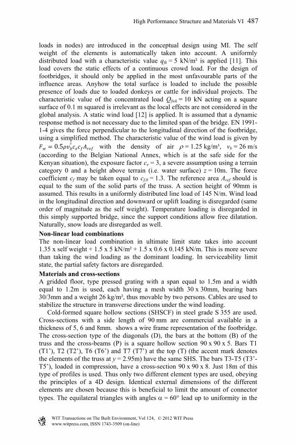
joints. Differ from the standard angle would require more holes in the junction plate for several angles of inclination of the diagonal truss members and thus a loss in capacity or even different junction plates. A single connection, applicable to all nodes, is designed. The total self weight of the structure (excl. cables, joints and gridded floor) is equal to 3448.5kg. The ratio between the applied load and the capacity in strength and stability (further on denoted as efficiency rate) is restricted to 0.90 taking into account an additional safety and fatigue effects. Under the loading conditions in ultimate limit state, a maximum design load both in tension and compression of 320 kN is obtained. This rules the analysis of the connections. For a number of triangles n = 7, thus a span of the bridge L = 21 m, a cross-section of 90 x 90 x 5 can be used anywhere with a maximum efficiency rate 0.88. Naturally for shorter bridges an element cross-section of type 90 x 90 x 5 suffices too. Consequently, the efficiency rate drops. For a number of triangles n = 3, thus a span of the bridge L = 9m, the efficiency rate drops to 0.6. Increasing this would allow to apply a cross-section of 80 x 80 x 5 but then the universality principle of the connection is affected adversely. The possibility of extending the span of the footbridge to 27m has been validated. Bars T2 (T2’) and T7 (T7’) at the top (T) (see Figure 1 but an additional triangle should be added) require a cross-section 90 x 90 x 8. The maximum efficiency rate equals 0.99 then. The connection just passed the ulterior verification based on the increased maximum design load (393 kN). The combined bending and shear in the pin determine the capacity of the connection. At least, a steel grade equivalent to a bolt class 8.8 is required.
Figure 1: Model of the footbridge (isometric view, elevation view and plan view).
P
L
T T T T T T T
B B B B B B B B
D1 D2 D3 D4 D5 D2 D3 D4 D5 D6 D7 D8 D9 D10 D12 H
X
Z
X
Y
488 High Performance Structure and Materials VI
www.witpress.com, ISSN 1743-3509 (on-line) WIT Transactions on The Built Environment, Vol 124, © 201 WIT Press2
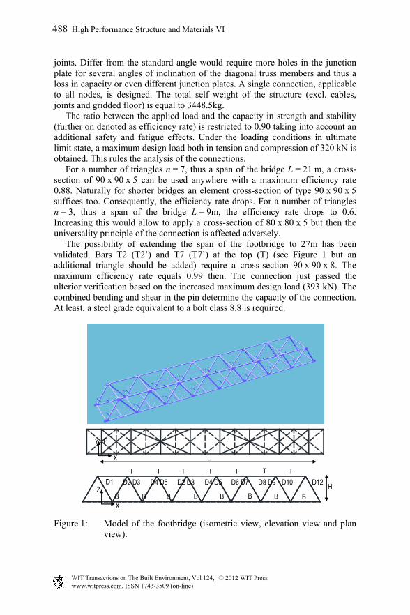
Connections Figure 2 shows the universal connection designed according to the Eurocode [10]. A pin is the load transmitting element between the truss members and the junction plates. To avoid shear and bending in the shank of the pin and bearing in the plate, a pin with a diameter = 35mm, and a steel grade equivalent to bolt class 8.8 are required. A fit with little clearance prevents slip in these connections. The pin is locked to the truss member by the application of some tag welds in the workshop.
Figure 2: Universal pin connection a) without junction plates, b) top view with junction plates, c) front view, d) bottom view, e) screwed connection and f) connection intermediate transverse beam.
Flat bars with a thickness of 10mm are used to increase the wall thickness of the truss members so that the requirements with respect to contact pressure and the end distance are satisfied. The criteria for bolts and rivets as well as for pin ended members (Table 3.3 and Table 3.9 of EN1993-1-8, 2005) are satisfied using an edge distance e1 = 42.5mm. A plate thickness of the junction plate of 10mm is preconceived with steel grade S355, so that also in this case the requirements for contact pressure and end distance are satisfied. The net area of the cross-section, taking into account deductions for all holes, is checked. The pinned truss members are positioned in the holes of the two junction plates. The whole connection is bolted together with three M16 8.8 bolts. Separation tubes around each of the bolts keep the junction plates at a pre-defined distance. A fourth screwed connection, consisting of a stud that is screwed into the bush that is fitted around the pin of the cross beam (see
a) b)
c) d)
e) f)
High Performance Structure and Materials VI 489
www.witpress.com, ISSN 1743-3509 (on-line) WIT Transactions on The Built Environment, Vol 124, © 201 WIT Press2
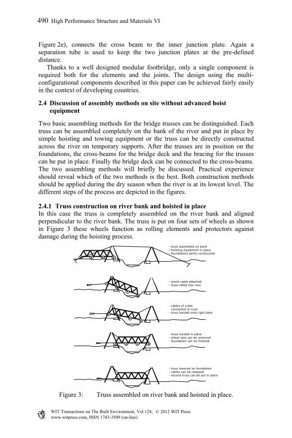
Figure 2e), connects the cross beam to the inner junction plate. Again a separation tube is used to keep the two junction plates at the pre-defined distance. Thanks to a well designed modular footbridge, only a single component is required both for the elements and the joints. The design using the multi-configurational components described in this paper can be achieved fairly easily in the context of developing countries.
2.4 Discussion of assembly methods on site without advanced hoist equipment
Two basic assembling methods for the bridge trusses can be distinguished. Each truss can be assembled completely on the bank of the river and put in place by simple hoisting and towing equipment or the truss can be directly constructed across the river on temporary supports. After the trusses are in position on the foundations, the cross-beams for the bridge deck and the bracing for the trusses can be put in place. Finally the bridge deck can be connected to the cross-beams. The two assembling methods will briefly be discussed. Practical experience should reveal which of the two methods is the best. Both construction methods should be applied during the dry season when the river is at its lowest level. The different steps of the process are depicted in the figures.
2.4.1 Truss construction on river bank and hoisted in place In this case the truss is completely assembled on the river bank and aligned perpendicular to the river bank. The truss is put on four sets of wheels as shown in Figure 3 these wheels function as rolling elements and protectors against damage during the hoisting process.
- truss assembled on bank- hoisting equipment in place- foundations partly constructed
- truss lowered on foundation- cables can be released- second truss can be put in place
- truss hoisted in place - wheel sets can be removed- foundation can be finished
- cables of crabs connected to truss- truss hoisted onto right bank
- winch cable attached- truss rolled into river
490 High Performance Structure and Materials VI
www.witpress.com, ISSN 1743-3509 (on-line) WIT Transactions on The Built Environment, Vol 124, © 201 WIT Press2
Figure 3: Truss assembled on river bank and hoisted in place.
The hoisting equipment consists of two hoists constructed at both banks above the foundations. Their approximate height is 4m and consist two times two legs of tubular steel connected by an I-beam on which a hoisting crab can move. They are connected with two cables and stabilised with four cabled ground anchors that dig themselves in when loaded. The cables can also be attached to trees when available. The foundations are completed up to ground level, so that the “rolling” truss is not blocked. The truss is rolled into the river but is hold back by a winch of a car. A pulley system can be used to reduce the traction on the car. When the truss is touching the other river bank it is hoisted up and the rolling continues until it is in position above the two foundations. The truss is then hoisted free from the foundations so that the wheels can be removed and the foundations completed. Finally the truss can be lowered onto the foundations.
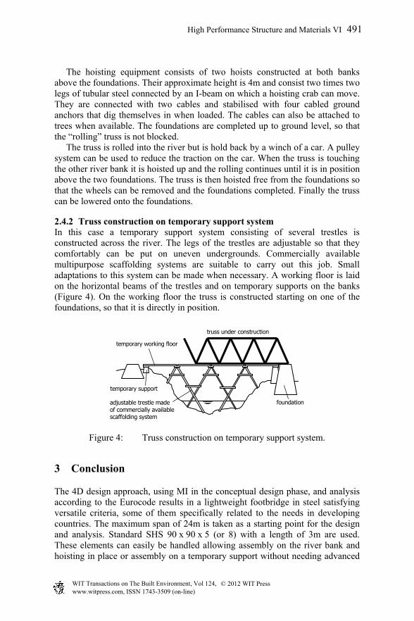
2.4.2 Truss construction on temporary support system In this case a temporary support system consisting of several trestles is constructed across the river. The legs of the trestles are adjustable so that they comfortably can be put on uneven undergrounds. Commercially available multipurpose scaffolding systems are suitable to carry out this job. Small adaptations to this system can be made when necessary. A working floor is laid on the horizontal beams of the trestles and on temporary supports on the banks (Figure 4). On the working floor the truss is constructed starting on one of the foundations, so that it is directly in position.
Figure 4: Truss construction on temporary support system.
3 Conclusion
The 4D design approach, using MI in the conceptual design phase, and analysis according to the Eurocode results in a lightweight footbridge in steel satisfying versatile criteria, some of them specifically related to the needs in developing countries. The maximum span of 24m is taken as a starting point for the design and analysis. Standard SHS 90 x 90 x 5 (or 8) with a length of 3m are used. These elements can easily be handled allowing assembly on the river bank and hoisting in place or assembly on a temporary support without needing advanced
foundation
temporary working floor
temporary support
adjustable trestle made of commercially availablescaffolding system
truss under construction
High Performance Structure and Materials VI 491
www.witpress.com, ISSN 1743-3509 (on-line) WIT Transactions on The Built Environment, Vol 124, © 201 WIT Press2

hoist equipment. The footbridge is thus modular, adaptable for other lengths, movable and re-usable. Due to a well designed concept, only one single component both for the elements and the joints is used.
Acknowledgements
The authors greatly acknowledge the financial support offered by VLIR-UOS in the Flemish Interuniversity Council – University Development Cooperation within this research project. The first author also acknowledges Lessius School for offering her the opportunity of one year’s activities at Vrije Universiteit Brussels.
References
[1] X. Tillez, “Ontwerp en analyse van een aanpasbare fundering voor tijdelijke constructies, Uitwerking voor de voetgangersbrug Kodoch-Landa (Kenya), Masterthesis,” Vrije Universiteit Brussel, 2010.
[2] R. Demeersman, “Structural design of reusable foundation, using the 4D design approach, Masterthesis,” Vrije Universiteit Brussel, 2010.
[3] P. Samyn, “Etude Comparée du Volume et du Déplacement de structures Isostatiques Bidimensionnelles Sous Charges Verticales Entre Deux Appuis, Thèse de doctorat,” Université de Liège, 1999.
[4] P. Latteur, “Optimisation et prédimensionnement des treillis, arcs, poutres et câbles sur base d’indicateurs morphologiques – Application aux structures soumises en partie ou en totalité au flambement, Thèse de doctorat,” Vrije Universiteit Brussel, 2000.
[5] J. Van Steirteghem, “A Contribution to the Optimisation of Structures Using Morphological Indicators : (In)Stability and Dynamics, PhD thesis,” Vrije Universiteit Brussel, 2006.
[6] B. Verbeeck, W. P. De Wilde, P. Samyn, and J. Van Steirteghem, “Use of Genetic Algorithms and Morphological Indicators in the Optimisation of 2D Trusses,” Proceedings of HPSM 2004, 2004.
[7] P. Samyn, Etude de la morphologie des structures à l’aide des indicateurs de volume et de déplacement. Académie royale de Belgique, 2004, p.482.
[8] P. Latteur, P. Samyn, and W. P. De Wilde, “Etude du poids et de la raideur des treillis Warren, Pratt et Howe Optimisation, prédimensionnement et comparaison sur base d’indicateurs morphologiques,” Revue Française de Génie Civile, vol. 4, 2000.
[9] EN1993-1-1, Eurocode 3: Design of steel structures - Part 1-1: General rules and rules for buildings. 2005.
[10] EN1993-1-8, Eurocode 3 - Part 1.8: Design of joints. 2005. [11] EN1991-2, Eurocode 1: Actions on structures - Part 2: Traffic loads on
bridges (+ AC:2010). 2004. [12] EN1991-1-4, Eurocode 1: Actions on structures - Part 1-4: General
actions - Wind actions. 2005.
492 High Performance Structure and Materials VI
www.witpress.com, ISSN 1743-3509 (on-line) WIT Transactions on The Built Environment, Vol 124, © 201 WIT Press2