Embed Size (px)
Citation preview

RSC Advances
PAPER
Ope
n A
cces
s A
rtic
le. P
ublis
hed
on 0
2 M
ay 2
019.
Dow
nloa
ded
on 1
/31/
2022
7:1
8:03
AM
. T
his
artic
le is
lice
nsed
und
er a
Cre
ativ
e C
omm
ons
Attr
ibut
ion-
Non
Com
mer
cial
3.0
Unp
orte
d L
icen
ce.
View Article OnlineView Journal | View Issue
Formation and c
aZhejiang Provincial Key Laboratory of
Technology, Zhejiang Sci-Tech University
[email protected]; [email protected] Dong Da Environment EngineerincZhejiang Kertice Hi-Tech Fluor-Material Co
Cite this: RSC Adv., 2019, 9, 13631
Received 5th March 2019Accepted 17th April 2019
DOI: 10.1039/c9ra01643k
rsc.li/rsc-advances
This journal is © The Royal Society of C
haracterization ofpolytetrafluoroethylene nanofiber membranes forhigh-efficiency fine particulate filtration
Huan Xu,a Wangyong Jin,b Feng Wang,ac Guojin Liu,a Chengcai Li,a Jieqi Wang,a
Hailin Zhu *ac and Yuhai Guo *a
Polytetrafluoroethylene (PTFE) porous membranes are widely used for high-temperature filtration. The
polytetrafluoroethylene nanofiber membranes for fine particulate filtration were prepared by sintering
the precursor electrospun polytetrafluoroethylene/polyvinyl/boric acid alcohol composite membranes.
The effects of PTFE/PVA mass ratio and sintering temperature on the morphology and properties of the
prepared membranes were investigated to obtain the PTFE nanofibers with different diameters, and the
film has been characterized by SEM, TG, XRD, FT-IR, and EDS, and the mechanical and hydrophobic
properties of the membranes were also investigated. The PTFE nanofiber membranes after sintering had
nanofiber and nanowire structures. Moreover, the membranes were tested in air filtration. The filtration
efficiency and pressure drop were tested to evaluate the membrane permeability and separation
properties. The results showed a high filtration efficiency (98%) and a low pressure drop (90 Pa) for
300 nm sodium chloride aerosol particles at a 30 L min�1 airflow velocity and the hydrophobic
membranes showed durable self-cleaning properties, which suggested that the PTFE nanofiber
membranes were a promising candidate for high temperature filtration applications.
1. Introduction
Air pollution, as a primary environmental problem, has attrac-ted increasing attention due to rapid urbanization and indus-trialization.1 More than two million premature deaths each yearcan be attributed to the effects of urban outdoor air pollutionand indoor air pollution, particularly in developing countries.2
Fine particles with an aerodynamic diameter less than 2.5 mm,were considered to be a major cause of adverse health effectsranging from the human respiratory tract to extrapulmonaryorgans.3–5 Moreover, stricter emission limits for ne particleemissions from industrial processes and automotive exhausthave also contributed to the urgent need for high performancelters with high ltration efficiency, low energy cost, and longservice life.6,7 The conventional ltration media, including melt-blown bers, glass lters, and spun-bonded bers, are known toexhibit relatively low ltration efficiency and high energyconsumption, as well as being unsuitable for the ltration ofne particles due to the micro-sized ber diameter and depthloading characteristics.8,9 Template synthesis, phase separation,melt-blown methods, and plasma treatment have been
Fiber Materials and Manufacturing
, Hangzhou, 310018, China. E-mail:
g Co., Ltd, Zhuji 311800, China
., Ltd, Huzhou 313000, China
hemistry 2019
developed to fabricate nanober-based membranes for separa-tion of ne particles.10–14 But most of the lters still suffer fromlow ltration efficiency and high energy consumption, as well asbeing unsuitable for the ltration of ne particles. In the pastdecade, electrospun nanobers have widely been used asbrous lters for air ltration.15–23 Electrospinning has emergedas a promising technology in air ltration and water purica-tion devices because of the advantageous features of control-lable ber diameter, high porosity, remarkable specic surfacearea, low packing density. Nevertheless, those membranes maynot be able to withstand high temperature for a long time.
Polytetrauoroethylene (PTFE) is well known for itsoutstanding thermal stability, chemical resistance, low surfaceenergy and good electrical insulation.24–28 Porous PTFEmembranes28–31 and PTFE bag lters32–34 have been widely usedas high-temperature lters. Most of the lters for hot gasltration are made of nonwoven fabrics of PTFE,35 PPS,36 glass,37
ceramic38 and metal ber.39 For PTFE nanober membrane, ithas potential as hot gas lter media and so far litter has beenreported about the application of PTFE nanober membranesfor hot gas ltration.
Due to the superior solvent resistance and the high meltviscosity,40,41 PTFE ber is prepared by the methods ofmembrane-splitting and paste-extrusion. In the preparationprocess, a lot of lubricants are used which may be harmful tothe environment. In this paper, PTFE nanober membraneswere prepared by sintering PTFE/PVA/BA electrospun
RSC Adv., 2019, 9, 13631–13645 | 13631
RSC Advances Paper
Ope
n A
cces
s A
rtic
le. P
ublis
hed
on 0
2 M
ay 2
019.
Dow
nloa
ded
on 1
/31/
2022
7:1
8:03
AM
. T
his
artic
le is
lice
nsed
und
er a
Cre
ativ
e C
omm
ons
Attr
ibut
ion-
Non
Com
mer
cial
3.0
Unp
orte
d L
icen
ce.
View Article Online
membranes (emulsion electrospinning). Emulsion electro-spinning is considered as green and environmental method tofabricate brous membranes from water based emulsionstogether with small amount of water soluble polymer asa matrix. This method not only could avoid using a largeamount of toxic organic solvents but also could be used toprocess unspinnable polymer particles into bers.42–45 We usedthe complexing property of BA and PVA and prepared spinningsolution by adding a little amount of BA solution into the mixedliquids with different mass concentrations of PVA and PTFEemulsion. PVA (10 wt%) was chosen as assistant spinning due toits water solubility, low cost, easy spinning property and lowdecomposition temperature. The effect of PTFE/PVA ratio andsintering temperature on the morphology and properties ofPTFE nanober membranes for air ltration are investigated.PTFE nanobrous membranes are designed for water resistantand breathability application because of the high hydropho-bicity, high fracture toughness and low surface friction. Furtherstudies show that the PTFE nanober membranes have highporosity and complex pore geometries that give the membraneshigh ltration efficiency with low pressure drop.
Thus far, Xiong et al.46 reported an inspiring work in whichbrous PTFE membranes were fabricated through electro-spinning and sintering and PTFE nanober membranes havebeen widely exploring and adopted for versatile application,such as dye degradation,47 photocatalytic degradation,48,49
waterproof-breathable application,50 vacuum membrane distil-lation,31,51 the separator for lithium-ion batteries,52 the high-performance triboelectric nanogenerators,53 the oil/water sepa-ration.54,55 However, research in air ltration has hardly beencarried out.
Fig. 1 Schematic diagram illustrating the fabrication of PTFE/PVAfibrous membranes and typical FE-SEM image of PTFE/PVAmembrane.
2. Experimental2.1 Materials
All materials were purchased commercially and were usedwithout further purication. PTFE emulsion (TE3859) in water(60%) was obtained from Dongguan Dongzhan plastic tradeCo., Ltd. The PTFE particles in the emulsion have an averagesize of 80 nm. PVA1799 was provided by Sichuan VinylonFactory (China) and boric acid (BA) was purchased from Zhe-jiang Transfar Technology Co., Ltd (China). The water used inthis work was distilled water.
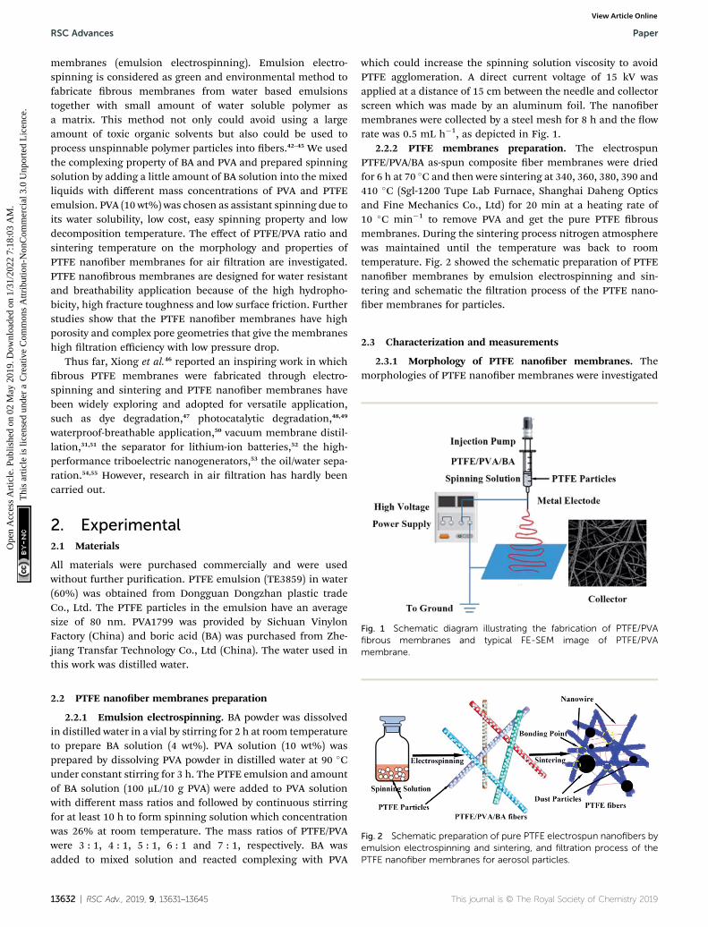
Fig. 2 Schematic preparation of pure PTFE electrospun nanofibers byemulsion electrospinning and sintering, and filtration process of thePTFE nanofiber membranes for aerosol particles.
2.2 PTFE nanober membranes preparation
2.2.1 Emulsion electrospinning. BA powder was dissolvedin distilled water in a vial by stirring for 2 h at room temperatureto prepare BA solution (4 wt%). PVA solution (10 wt%) wasprepared by dissolving PVA powder in distilled water at 90 �Cunder constant stirring for 3 h. The PTFE emulsion and amountof BA solution (100 mL/10 g PVA) were added to PVA solutionwith different mass ratios and followed by continuous stirringfor at least 10 h to form spinning solution which concentrationwas 26% at room temperature. The mass ratios of PTFE/PVAwere 3 : 1, 4 : 1, 5 : 1, 6 : 1 and 7 : 1, respectively. BA wasadded to mixed solution and reacted complexing with PVA
13632 | RSC Adv., 2019, 9, 13631–13645
which could increase the spinning solution viscosity to avoidPTFE agglomeration. A direct current voltage of 15 kV wasapplied at a distance of 15 cm between the needle and collectorscreen which was made by an aluminum foil. The nanobermembranes were collected by a steel mesh for 8 h and the owrate was 0.5 mL h�1, as depicted in Fig. 1.
2.2.2 PTFE membranes preparation. The electrospunPTFE/PVA/BA as-spun composite ber membranes were driedfor 6 h at 70 �C and then were sintering at 340, 360, 380, 390 and410 �C (Sgl-1200 Tupe Lab Furnace, Shanghai Daheng Opticsand Fine Mechanics Co., Ltd) for 20 min at a heating rate of10 �C min�1 to remove PVA and get the pure PTFE brousmembranes. During the sintering process nitrogen atmospherewas maintained until the temperature was back to roomtemperature. Fig. 2 showed the schematic preparation of PTFEnanober membranes by emulsion electrospinning and sin-tering and schematic the ltration process of the PTFE nano-ber membranes for particles.
2.3 Characterization and measurements
2.3.1 Morphology of PTFE nanober membranes. Themorphologies of PTFE nanober membranes were investigated
This journal is © The Royal Society of Chemistry 2019

Fig. 3 Schematic diagram of the experimental setup for a particulategeneration, filtration, and measurement system.
Paper RSC Advances
Ope
n A
cces
s A
rtic
le. P
ublis
hed
on 0
2 M
ay 2
019.
Dow
nloa
ded
on 1
/31/
2022
7:1
8:03
AM
. T
his
artic
le is
lice
nsed
und
er a
Cre
ativ
e C
omm
ons
Attr
ibut
ion-
Non
Com
mer
cial
3.0
Unp
orte
d L
icen
ce.
View Article Online
with a FESEM equipped with an X-ray energy dispersive spec-trometer (EDS) (EVO MA 25, ZEISS, Germany). The PTFEnanober membranes were frozen in liquid nitrogen, fracturedto obtain fragments, and sputtered with platinum usinga HITACHI E-1010 Ion Sputtering device for FESEM observa-tion. EDS detector was used to determine the existence of PVA.
2.3.2 Porosity and pore size distribution. The over porositywas usually determined by the gravimetric method, deter-mining the weight of liquid contained in the membrane pores.The porosity 3 of the PTFE nanober membrane was calculatedby the following equation:
3 ¼ w1 � w2=rlw1 � w2=rl þ w2=r
(1)
Here, w1 is the weight of the wet PTFE nanober membrane, w2
is the weight of the dry PTFE nanober membrane, rl is theliquid density, which equals 0.816 g mL�1, and r is the polymerdensity, which the density of PTFE is 2.2 g mL�1. The pore sizedistribution of the PTFE nanober membranes was investigatedby using a Capillary Flow Porometer (Porometer 3GZH Quan-tachrome Instruments, USA). The nanober membranes werefully wetted with the Gq16, and then the measurements werecarried out following the procedure described in the literature.56
The pore size distribution was determined with the aid of thecomputer soware coupled to the capillary ow porometer.
2.3.3 Contact angle. The contact angles of the membraneswere measured by a contact angle measuring system (SL200KB,America).
2.3.4 Mechanical strength and thickness. The tensilemechanical property was measured on a tensile tester (KEG-G1,Kato-Tech Co., Ltd. Japan). Strip samples with a width of 5 mmand a length of 40 mm were tested with a crosshead speed of 10mm min�1. The thickness of the samples was measured bya screw micrometer. All the samples were tested for 5 times togive the average values.
2.3.5 IR and XRD examination. The Fourier transforminfrared (FTIR) spectra was recorded on a Nicolet 5700 spec-trometer (Thermo Fisher Scientic, USA) to determine theresidual extent of PVA in each sample before or aer sinteringtreated. X-ray diffraction (XRD, Bruker D8, Germany) was usedto elucidate the crystal structure of samples.
2.3.6 DSC and TGA examination. The differential scanningcalorimeter (DSC, NETZSCH DSC 200PC) analysis of the PTFEnanober membrane was performed to determine the meltingtemperature. For the purpose of getting the initial soeningtemperature, samples were heated up from 30 to 380 �C ata heating rate of 10 �C min�1. Thermal stabilities were exam-ined by thermogravimetric analyser (TGA, Seiko-6300, Japan) innitrogen atmosphere with a heating rate of 10 �C min�1.
2.4 Applications of air ltration
A TSI Model 8130 Automated Filter Tester (TSI, Inc., MN, USA)was used tomeasure the ltration efficiency and lter resistance(Fig. 3). The device is attached to a particle generator whichgenerates charge neutralized micron monodisperse solid NaClparticles of 0.3 mm in diameter. The neutralized NaCl aerosols
This journal is © The Royal Society of Chemistry 2019
were fed into a lter holder and down through the lter with 100cm2 of effective area. Two, solid-state, laser photometers enablethese lter testers to measure aerosol concentration levels bothupstream and downstream of the lter under testing. The lterresistance was measured with a combination of a ow meterand two electronic pressure transducers that detected thepressure drop through the lter media under testing. All NaClaerosol tests were conducted at room temperature. The airbefore and aer the membrane lters was sampled, and theltration efficiency of the membrane lter was determinedusing
h ¼ (C0 � C)/C0 (2)
where C0 and C correspond to the particle number concentra-tion before and aer the membrane lters.
The quality factor (QF), which is usually taken as the crite-rion for comparing ltration performance of different lters, isexpressed as:57
QF ¼ lnð1� hÞDP
(3)
where h and DP is the ltration efficiency and pressure drop,respectively. The higher collection efficiency with lower possiblepressure drop result in a better lter media.
3. Result and discussion3.1 Effects of solution parameters on ber morphology
The SEM images of themembranes prepared by electrospinningunder certain condition and the mass ratios of PTFE/PVA were3 : 1, 4 : 1, 5 : 1, 6 : 1 and 7 : 1, respectively were shown in Fig. 4.In order to improve the mechanical and ltration performanceof PTFE nanober membrane, the bers should be uniformwithout a lot of beads. When the mass ratios of PTFE/PVA were6 : 1 and 7 : 1, many beads and needle-like short bers
RSC Adv., 2019, 9, 13631–13645 | 13633

Fig. 4 Morphologies of precursor electrospun PTFE/PVA composite membranes at different PTFE/PVAmass ratios ((a1 and a2), 3 : 1; (b1 and b2),4 : 1; (c1 and c2), 5 : 1; (d1 and d2), 6 : 1; (e1 and e2), 7 : 1; a1–e1, �2000 surface; a2–e2, �5000 surface).
RSC Advances Paper
Ope
n A
cces
s A
rtic
le. P
ublis
hed
on 0
2 M
ay 2
019.
Dow
nloa
ded
on 1
/31/
2022
7:1
8:03
AM
. T
his
artic
le is
lice
nsed
und
er a
Cre
ativ
e C
omm
ons
Attr
ibut
ion-
Non
Com
mer
cial
3.0
Unp
orte
d L
icen
ce.
View Article Online
appeared. This morphology (Fig. 4(d) and (e)) could be becausethe amount of PVA was too small to efficiently binder the PTFEnanoparticles each other into a continuous ber form. The
13634 | RSC Adv., 2019, 9, 13631–13645
beads decreased and the bers became continuous byincreasing the PVA amount (Fig. 4(a)–(c)). The precursor nano-bermembrane was composed of a random array of nanobers.
This journal is © The Royal Society of Chemistry 2019
Paper RSC Advances
Ope
n A
cces
s A
rtic
le. P
ublis
hed
on 0
2 M
ay 2
019.
Dow
nloa
ded
on 1
/31/
2022
7:1
8:03
AM
. T
his
artic
le is
lice
nsed
und
er a
Cre
ativ
e C
omm
ons
Attr
ibut
ion-
Non
Com
mer
cial
3.0
Unp
orte
d L
icen
ce.
View Article Online
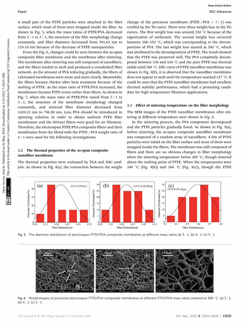
A small part of the PTFE particles were attached to the bersurface, which most of them were wrapped inside the ber. Asshown in Fig. 5, when the mass ratios of PTFE/PVA decreasedfrom 5 : 1 to 3 : 1, the structure of the lm morphology changeconstantly, and ber diameter decreased from 591.63 nm to219.10 nm because of the decrease of PTFE nanoparticles.
From the Fig. 6, changes could be seen between the as-spuncomposite ber membrane and the membrane aer sintering.Themembrane aer sintering was still composed of nanobers,and the bers tended to melt and produced a crosslinked bernetwork. As the amount of PVA reducing gradually, the bers ofcalcinated membranes were more andmore clearly. Meanwhile,the bers became thicker aer heat treatment because of themelting of PTFE. As the mass ratio of PTFE/PVA increased, themembranes became PTFE resins rather than bers. As shown inFig. 7, when the mass ratio of PTFE/PVA varied from 5 : 1 to3 : 1, the structure of the membrane morphology changedconstantly, and sintered ber diameter decreased from1420.15 nm to 796.90 nm. Less PVA should be introduced inspinning solution in order to obtain uniform PTFE bermembranes and the thinner bers were good for air ltration.Therefore, the electrospun PTFE/PVA composite bers and theirmembranes from the blend with the PTFE : PVA weight ratio of4 : 1 were used for the following investigations.
3.2 The thermal properties of the as-spun compositenanober membrane
The thermal properties were evaluated by TGA and DSC anal-ysis. As shown in Fig. 8(a), the connection between the weight
Fig. 5 The diameter distribution of electrospun PTFE/PVA composite m
Fig. 6 Morphologies of precursor electrospun PTFE/PVA composite me(b) 4 : 1; (c) 5 : 1.
This journal is © The Royal Society of Chemistry 2019
change of the precursor membrane (PTFE : PVA ¼ 7 : 3) wasveried by the TG curve. There were three weight-loss in the TGcurves. The rst weight loss was around 250 �C because of thevaporization of surfactant. The second weight loss occurredbetween 300–350 �C, which was corresponding to the decom-position of PVA. The last weight loss started at 500 �C, whichwas attributed to the decomposition of PTFE. The result showedthat the PTFE was preserved well. The PVA completely decom-posed between 330 and 430 �C and the pure PTFE was thermalstable until 500 �C. DSC curve of PTFE nanobermembrane wasshown in Fig. 8(b), it is observed that the nanober membranedoes not appear to melt until the temperature reached 327 �C. Itcould be seen that the PTFE nanober membrane had excellentthermal stability performance, which had a promising candi-date for high temperature ltration applications.
3.3 Effect of sintering temperature on the ber morphology
The SEM images of the PTFE nanober membranes aer sin-tering at different temperature were shown in Fig. 9.
In the sintering process, the PVA component decomposedand the PTFE particles gradually fused. As shown in Fig. 9(a),before sintering, the as-spun composite nanober membranewas composed of a random array of nanobers. A few of PTFEparticles were inlaid on the ber surface and most of them werewrapped inside the bers. The membrane was still composed ofbers and there are no obvious changes in ber morphologywhen the sintering temperature below 380 �C, though sinteredabove the melting point of PTFE. When the temperatures were340 �C (Fig. 9(b)) and 360 �C (Fig. 9(c)), though the PTFE
embranes at different mass ratios (a) 3 : 1; (b) 4 : 1; (c) 5 : 1.
mbranes at different PTFE/PVA mass ratios sintered at 380 �C, (a) 3 : 1;
RSC Adv., 2019, 9, 13631–13645 | 13635

Fig. 7 The diameter distribution of electrospun PTFE/PVA composite membranes at different mass ratios sintered at 380 �C (a) 3 : 1; (b) 4 : 1; (c)5 : 1.
Fig. 8 (a) TG curve of the as-spun composite membrane, PVA and PTFE nanofiber membrane; (b) DSC curve of PTFE nanofiber membrane.
RSC Advances Paper
Ope
n A
cces
s A
rtic
le. P
ublis
hed
on 0
2 M
ay 2
019.
Dow
nloa
ded
on 1
/31/
2022
7:1
8:03
AM
. T
his
artic
le is
lice
nsed
und
er a
Cre
ativ
e C
omm
ons
Attr
ibut
ion-
Non
Com
mer
cial
3.0
Unp
orte
d L
icen
ce.
View Article Online
particles began to melt and the bers showed consecutively,some PTFE particles still appeared on the surface of the bers.The morphology of the membrane treated at 380 and 390 �Cwere shown in Fig. 9(d) and (e). The membranes were stillcomposed of a random array of nanobers, but on the bercrosslinking points, the bers tended to melt in the bersintersections resulting in bonding and formed a connectedber mesh structure. On the ber surface, grooves arrangedtransversely due to the PTFE melted and uxed to ll the cavi-ties caused by the PVA decomposition to keep the ber shape.The unique structures provided the multiple scale roughness,which was not only important for forming hydrophobic surface,but also important for improving the effective area for airltration. As shown in Fig. 9(f), further increasing the temper-ature to 410 �C led to the shrinkage of bers and junction-formation between bers. This mechanical performance ofthe PTFE membrane sintering at 410 �C might be due to thehigh temperature (410 �C) leading to partial degradation ofPTFE macromolecular chain.
3.4 The effect of sintering temperature on the compositionof the bers
Further investigation by EDS was performed to prove the effectof sintering temperature on the composition of the bers. It wasshown in Fig. 10, the EDS patterns revealed that the as-spun
13636 | RSC Adv., 2019, 9, 13631–13645
nanober membranes surface contained C, O, and F, whichthree characterized peaks were at 0.27, 0.52 and 0.68 keV. Whenthe sintering temperatures were 340 �C and 360 �C, the threecharacterized peaks still appeared. It showed that there was stilla small amount of PVA in PTFE nanober membranes. Aer thesintering temperature above 380 �C, the signal form oxygenelement was disappeared. The pure PTFE nanobermembranescould be got when the sintering temperature was above 380 �C.
The chemical structure and composition of before and aersintering (380 �C) were conrmed by FT-IR as shown in Fig. 11.The bands around 1210 and 1155 cm�1 were assigned for C–Fstretching vibrations, and the brands near 2937 and 3315 cm�1
are characteristic for PVA. When the stretching temperatureincreased at 380 �C, the characteristic bands for PVA dis-appeared because of the decomposition of PVA. The resultshowed that the PVA was completely removed, and PTFEnanober membranes were successfully prepared.
3.5 The effect of sintering temperature on the crystallinity ofthe PTFE nanober membranes
The X-ray diffraction pattern of pure PTFE nanobermembranes was shown in Fig. 12. There were peaks observed at2q ¼ 18.15�, 31.8�, 37.15� and 41.5�, which could be indexed to(100), (110), (107) and (108) of PTFE, respectively. The peak at 2q¼ 18.15� was considered as the crystallinity phase of PTFE while
This journal is © The Royal Society of Chemistry 2019
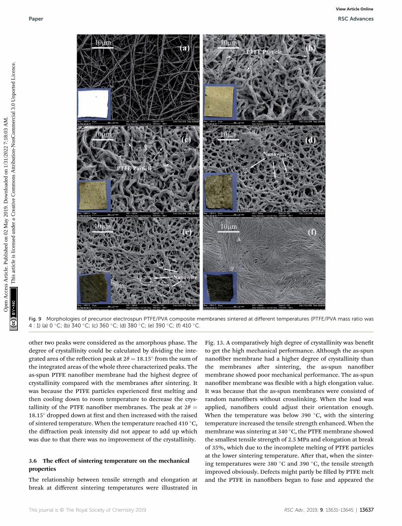
Fig. 9 Morphologies of precursor electrospun PTFE/PVA composite membranes sintered at different temperatures (PTFE/PVA mass ratio was4 : 1) (a) 0 �C; (b) 340 �C; (c) 360 �C; (d) 380 �C; (e) 390 �C; (f) 410 �C.
Paper RSC Advances
Ope
n A
cces
s A
rtic
le. P
ublis
hed
on 0
2 M
ay 2
019.
Dow
nloa
ded
on 1
/31/
2022
7:1
8:03
AM
. T
his
artic
le is
lice
nsed
und
er a
Cre
ativ
e C
omm
ons
Attr
ibut
ion-
Non
Com
mer
cial
3.0
Unp
orte
d L
icen
ce.
View Article Online
other two peaks were considered as the amorphous phase. Thedegree of crystallinity could be calculated by dividing the inte-grated area of the reection peak at 2q¼ 18.15� from the sum ofthe integrated areas of the whole three characterized peaks. Theas-spun PTFE nanober membrane had the highest degree ofcrystallinity compared with the membranes aer sintering. Itwas because the PTFE particles experienced rst melting andthen cooling down to room temperature to decrease the crys-tallinity of the PTFE nanober membranes. The peak at 2q ¼18.15� dropped down at rst and then increased with the raisedof sintered temperature. When the temperature reached 410 �C,the diffraction peak intensity did not appear to add up whichwas due to that there was no improvement of the crystallinity.
3.6 The effect of sintering temperature on the mechanicalproperties
The relationship between tensile strength and elongation atbreak at different sintering temperatures were illustrated in
This journal is © The Royal Society of Chemistry 2019
Fig. 13. A comparatively high degree of crystallinity was benetto get the high mechanical performance. Although the as-spunnanober membrane had a higher degree of crystallinity thanthe membranes aer sintering, the as-spun nanobermembrane showed poor mechanical performance. The as-spunnanober membrane was exible with a high elongation value.It was because that the as-spun membranes were consisted ofrandom nanobers without crosslinking. When the load wasapplied, nanobers could adjust their orientation enough.When the temperature was below 390 �C, with the sinteringtemperature increased the tensile strength enhanced. When themembrane was sintering at 340 �C, the PTFEmembrane showedthe smallest tensile strength of 2.5 MPa and elongation at breakof 35%, which due to the incomplete melting of PTFE particlesat the lower sintering temperature. Aer that, when the sinter-ing temperatures were 380 �C and 390 �C, the tensile strengthimproved obviously. Defects might partly be lled by PTFE meltand the PTFE in nanobers began to fuse and appeared the
RSC Adv., 2019, 9, 13631–13645 | 13637

Fig. 10 EDS curves of PTFE/PVA precursor membranes before (a) and sintered different temperatures (b) 340 �C; (c) 360 �C; (d) 380 �C (PTFE/PVA mass ratio was 4 : 1).
RSC Advances Paper
Ope
n A
cces
s A
rtic
le. P
ublis
hed
on 0
2 M
ay 2
019.
Dow
nloa
ded
on 1
/31/
2022
7:1
8:03
AM
. T
his
artic
le is
lice
nsed
und
er a
Cre
ativ
e C
omm
ons
Attr
ibut
ion-
Non
Com
mer
cial
3.0
Unp
orte
d L
icen
ce.
View Article Online
crosslinking point to form an interconnected brous networkstructure. The membranes could be stronger with the help ofthe bonding between the bers. The tensile strength of themembranes treated at 410 �C was weaker than that of themembranes treated at 380 �C and 390 �C. The mechanicalproperties of nanober membranes decreased when curing athigher temperatures although the temperatures were lowerthan the decomposition temperature of PTFE. This mechanicalperformance of the PTFE membrane sintering at 410 �C mightbe due to the high temperature (410 �C) leading to partialdegradation of PTFE macromolecular chain.
Fig. 11 IR spectrums of PTFE nanofiber membrane and precursormembrane.
13638 | RSC Adv., 2019, 9, 13631–13645
3.7 The hydrophobicity of the pure nanober membrane
Hydrophobicity was an important property for air ltration,which could make membranes have the property of durableself-cleaning. The water contact angle of sintered membranestreated at different temperatures and different mass ratios wasshown in Fig. 14, Tables 1 and 2. The water contact angle of theas-spun nanober membrane was calculated to be about 28�
(Fig. 14(c)). It was due to that the as-spun nanober membraneshad a PVA concentration of about 20% and the huge specicsurface area because of the ultrane brous structure. When
Fig. 12 XRD patterns of PTFE/PVA precursor membranes sintereddifferent temperatures.
This journal is © The Royal Society of Chemistry 2019

Paper RSC Advances
Ope
n A
cces
s A
rtic
le. P
ublis
hed
on 0
2 M
ay 2
019.
Dow
nloa
ded
on 1
/31/
2022
7:1
8:03
AM
. T
his
artic
le is
lice
nsed
und
er a
Cre
ativ
e C
omm
ons
Attr
ibut
ion-
Non
Com
mer
cial
3.0
Unp
orte
d L
icen
ce.
View Article Online
the mass ratios of the PTFE/PVA membranes increased from3 : 1 to 5 : 1, more and more PTFE particles were attached to theber surface, which increased the roughness of the membranes
Fig. 13 Stress–strain curves of the PTFE/PVA precursor membranes sin
Fig. 14 The water contact angle of PTFE nanofiber membranes (a) difftemperatures, the PTFE/PVA mass ratio was 4 : 1; (c) as-spun composite
This journal is © The Royal Society of Chemistry 2019
and improved the water contact angle. Aer sintering atdifferent temperatures, the membranes became hydrophobicand the water contact angle varies with increasing the sintering
tered different temperatures (PTFE/PVA mass ratio was 4 : 1).
erent PTFE/PVA mass ratios, sintered at 380 �C; (b) different sinteringmembrane.
RSC Adv., 2019, 9, 13631–13645 | 13639

Table 1 The properties of PTFE nanofiber membranes at different PTFE/PVA mass ratios at a sintering temperature of 380 �C
Samples Thickness (mm) Water contact angle (�)Mean diameter ofPTFE membranes (mm) Porosity (%)
3 : 1 28 � 2.0 138.89 � 0.8 1.7 � 0.03 86.3 � 2.54 : 1 25 � 2.0 140.09 � 0.7 1.82 � 0.08 84.4 � 1.35 : 1 32 � 1.0 142.56 � 0.9 1.97 � 0.06 80.6 � 3.8
Table 2 The properties of PTFE nanofiber membranes prepared at different temperatures (the mass ratio of PTFE/PVA was 4 : 1)
Samples Thickness (mm) Water contact angle (�)Mean pore size ofPTFE membranes (mm) Porosity (%)
340 �C 25 � 1.0 135.98 � 0.6 1.9 � 0.12 78.9 � 3.5360 �C 24 � 2.0 137.97 � 0.8 1.85 � 0.06 82.3 � 2.8380 �C 23 � 3.0 140.09 � 0.7 1.82 � 0.08 84.4 � 1.3390 �C 23 � 2.0 142.91 � 0.9 1.76 � 0.11 86.3 � 3.4
RSC Advances Paper
Ope
n A
cces
s A
rtic
le. P
ublis
hed
on 0
2 M
ay 2
019.
Dow
nloa
ded
on 1
/31/
2022
7:1
8:03
AM
. T
his
artic
le is
lice
nsed
und
er a
Cre
ativ
e C
omm
ons
Attr
ibut
ion-
Non
Com
mer
cial
3.0
Unp
orte
d L
icen
ce.
View Article Online
temperature. When the sintering temperatures were 340 �C and360 �C, the values of the water contact angle were lower thanthat of 380 �C, 390 �C and 410 �C due to the existence of PVA.There was no precise rule to describe the water contact angleincreasing tendency. The low surface and the roughness onmultiple scales were two important facts to form the hydro-phobic surface.
3.8 The pore size and porosity of the pure nanobermembranes
The pore size distribution and pore size of the prepared PTFEnanober membrane were measured and the results were pre-sented in Fig. 15, Tables 1 and 2. The PTFE nanobermembranes had a suitable pore size and a uniform pore sizedistribution, which was good for high-efficiency ne particulateltration. As the mass ratio of PTFE/PVA increased from 3 : 1 to5 : 1, a slight increase was seen in the pore size. The increase inthe pore size of relevant membranes could be owing to theincrease ber diameter with increasing the PTFE particles. Itcould be seen that when the mass ratio of PTFE/PVA reached6 : 1, the nanober membranes were showed to be PTFE resins
Fig. 15 The pore size of PTFE nanofiber membranes with different (a)temperature (PTFE/PVA mass ratio: 4 : 1).
13640 | RSC Adv., 2019, 9, 13631–13645
rather than bers. For this structure of the precursormembranes, it was difficult for the PTFE particles to fusetogether which prevented the formation of an interconnectedbrous network and made the mean pore size of themembranes aer sintering larger. Meanwhile, it could be seenthat the pore sizes of the PTFE nanober membranes decreasedwith the increase of sintering temperature. The membrane wasstill shown to ber assembled, but on the ber crossover points,the bers tend to fuse together and led to an interconnectedbrous network. When the sintering temperature was 410 �C,the high temperature might lead to the shrinkage of bers andjunction-formation between bers. That was why the smallerpore size with higher sintering temperature.
The porosity of the membrane was an important parameteraffecting air ltration application. It was well known that themembrane with higher porosity had higher permeate uxes andlower transmembrane pressure. The porosity of the PTFEnanober membrane was shown in Tables 1 and 2. It could beseen that the membrane porosity kept stable at about 83%.With the increase of the sintering temperature, the porosityincreased slightly because of increasing space le by decom-posing PVA component and a slight decrease in mean pore size.
PTFE/PVA mass ratios, (sintering temperature: 380 �C); (b) sintering
This journal is © The Royal Society of Chemistry 2019

Paper RSC Advances
Ope
n A
cces
s A
rtic
le. P
ublis
hed
on 0
2 M
ay 2
019.
Dow
nloa
ded
on 1
/31/
2022
7:1
8:03
AM
. T
his
artic
le is
lice
nsed
und
er a
Cre
ativ
e C
omm
ons
Attr
ibut
ion-
Non
Com
mer
cial
3.0
Unp
orte
d L
icen
ce.
View Article Online
3.9 Air purication tests
3.9.1 Effect of PTFE/PVA mass ration on air ltration. Forair ltration materials or air ltration units, ltration efficiencyand pressure drop were two important indicators to study theseparation behavior of brous membranes towards particles,which directly characterize the resistance of brous media withdifferent structures to particle mobility. The neutralized NaClaerosols were fed into a lter holder and down through the lterwith 100 cm2 of effective area. The ltration performance ofPTFE nanober membranes aer sintering at 380 �C withdifferent PTFE/PVA mass ration under the industrial standardface velocity of 30 L min�1 was demonstrated in Fig. 16.Filtration efficiency of nanobrous mats was dependent onber structural properties, especially for ber diameter andpore size.
As shown in Fig. 16, the ltration efficiency of precursormembranes with different mass ratios that were from 3 : 1 to5 : 1 aer sintering decreased from 98.6789% to 96.3871%,which could be attributed to the increasing size of average berdiameter leading to the increased pore size of the membranes.The increase in the pore size was revealed with the increase inber diameter, and the maximum pore size value for pure PTFEmembranes was obtained from the precursor membranes withthe mass ration that was 5 : 1. In case of highly porousmembranes ow takes place through shorter and less tortuouspath resulting in a smaller air ow pressure drop with highpermeability. Interestingly, when the PTFE/PVA mass ratio was5 : 1, the decrease of ltration efficiency was not obvious, whichwas due to the increase of roughness and surface area. On theone hand, the increased ltration efficiency of the roughmembranes compared with smooth membranes could becontributed to increased projected frontal area constructed. Onthe other hand, by imposing a pressure gradient across theprotrusions modied rough bers during the ltration gener-ates more streamlined ber geometry with lower pressure dropcompared with smooth membranes, which could be due to theincreased stagnation region formed by boundary layers madearound the rough ber. We could conclude that the roughnessstructure creates higher ltration efficiency and facilitates thepenetration of air ow through the membranes, which wasimportant to improve the ltration properties. Meanwhile, thepressure drop of PTFE membranes decreased with increasing
Fig. 16 Filtration performance of PTFE nanofiber membranes with differepressure drop (b) quality factor values.
This journal is © The Royal Society of Chemistry 2019
the pore size and ber diameter, which indicated the key role ofthe mass ratio of PTFE and PVA for decreasing the pressuredrop. The QF values of 0.04384, 0.04404 and 0.04236 for thePTFE membranes sintering from the precursor membraneswith different mass ratios from 3 : 1 to 5 : 1, conrming thecrucial role the widely distributed 2D nanonets towards theconstruction of brous medium for air ltration, especially forpractical applications in the energy saving society.
3.9.2 Effect of sintering temperature on air ltration. Theltration performance of tested PTFE nanober membranes inrelation to sintering temperature was shown in Fig. 17. It couldbe seen from Fig. 15 and Table 2 that the pore size decreasedwith the rise of sintering temperature when themembranes hadsame PTFE/PVA mass ratio. What was more, the pure nanobermembranes had similar porosity which kept stable at above80% when the sintering temperatures were 340 �C, 360 �C,380 �C, 390 �C. The ltration performance of PTFE nanobermembranes aer sintering at different sintering temperatureswith the same PTFE/PVA mass ration under the industrialstandard face velocity of 30 L min�1 was demonstrated inFig. 17. The ltration efficiency of PTFE nanober membranesaer sintering at different temperatures increased from96.7826% to 98.0560%, which might arise from the fact that theincreased sintering temperature thus lead to the decreased poresize of the relevant brous membranes. Moreover, the pressuredrop of PTFE nanober membranes increased from 80.3 Pa to96.3 Pa on the basis of the decreased pore size, which indicatedthe key role of pore structure in regulating the ltrationperformance.
Interestingly, as shown in Fig. 18, on the membranes aersintering, the abrasion produced many nanowires on the bersurface which could be owing to that the PTFE dispersing resinproduced nanowires under the action of shear force. PTFEnanowire was reported in the study,50 which was produced bythe abrasion on the ber surface that beneted to improve thehydrophobicity. It was known that PTFE molecules had a long,straight carbon backbone to which the uorine atoms werebonded. The electron cloud of the uorine atoms a uniformhelical sheath and such unbranched molecule lead to the highcrystallinity. The crystalline form of PTFE changes froma triclinic to a hexagonal lattice at 19 �C. Such transition soensthe PTFE particles and then slip of PTFE molecular chain took
nt PTFE/PVA mass ratios (sintered at 380 �C) (a) filtration efficiency and
RSC Adv., 2019, 9, 13631–13645 | 13641

Fig. 17 Filtration performance of PTFE nanofiber membranes with different sintering temperatures (PTFE/PVA mass ratio: 4 : 1) (a) filtrationefficiency and pressure drop (b) quality factor values.
Fig. 18 Morphologies of PTFE nanowire (a) �2000 surface; (b) �5000 surface; (c) �10 000 surface.
RSC Advances Paper
Ope
n A
cces
s A
rtic
le. P
ublis
hed
on 0
2 M
ay 2
019.
Dow
nloa
ded
on 1
/31/
2022
7:1
8:03
AM
. T
his
artic
le is
lice
nsed
und
er a
Cre
ativ
e C
omm
ons
Attr
ibut
ion-
Non
Com
mer
cial
3.0
Unp
orte
d L
icen
ce.
View Article Online
place under the action of external tension above 19 �C, whichresults in the formation of brils. This structure was a benet toimprove the ltration efficiency but not increase the pressuredrop. By considering the high ltration and low pressure drop,when the sintering temperature was 380 �C, the PTFE nanobermembranes exhibited huge advantages in contrast to otherltration media under the same ltration condition.
3.9.3 Effect of face velocity on air ltration. As could beseen in Fig. 19, the ltration efficiency of these four kinds ofmembranes sintered at different temperatures showed thesame variation behaviors with increasing the face velocity.With an increase in the face velocity, the membranes
Fig. 19 (a) Pressure drop versus face velocity of the PTFE membranes withe PTFE membranes with different temperatures.
13642 | RSC Adv., 2019, 9, 13631–13645
remained high ltration efficiency and had no obvious change.The PTFE nanober membranes exhibited almost nosubstantive change even at the face velocity of 90 L min�1
which was due to the contribution of the nanonet onimproving the ltration efficiency based on physical sievingmanner, especially under a high face velocity. The curves ofpressure drop versus the face velocity were shown in Fig. 19.The pressure drop increased with increasing the face velocityand both of them showed a linear relationship, which wasrelated to that the air ow in the media was typically in lowReynolds number regime, thus the stocks ow regime wasconsidered to prevail in all PTFE membranes.
th different temperatures; (b) filtration efficiency versus face velocity of
This journal is © The Royal Society of Chemistry 2019
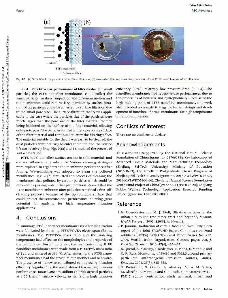
Fig. 20 (a) Simulated the process of surface filtration; (b) simulated the self-cleaning process of the PTFE membranes after filtration.
Paper RSC Advances
Ope
n A
cces
s A
rtic
le. P
ublis
hed
on 0
2 M
ay 2
019.
Dow
nloa
ded
on 1
/31/
2022
7:1
8:03
AM
. T
his
artic
le is
lice
nsed
und
er a
Cre
ativ
e C
omm
ons
Attr
ibut
ion-
Non
Com
mer
cial
3.0
Unp
orte
d L
icen
ce.
View Article Online
3.9.4 Repetitive-use performance of lter media. For smallparticles, the PTFE nanober membranes could collect thesmall particles via direct impaction and Brownian motion andthe membranes could remove large particles by surface ltra-tion. Most particles could be collected by surface ltration dueto the small pore size. The surface ltration theory was appli-cable to the case where the particles size of the particles weremuch larger than the pore size of the lter material, therebybeing hindered on the surface of the lter material, allowingonly gas to pass. The particles formed a lter cake on the surfaceof the lter material and continued to exert the ltering effect.The material suitable for the theory was easy to be cleaned, thedust particles were not easy to enter the lter, and the servicelife was relatively long. Fig. 20(a) and 2 simulated the process ofsurface ltration.
PTFE had the smallest surface tension in solid materials anddid not adhere to any substance. Various cleaning strategieswere explored to regenerate the membrane performance aerfouling. Water-swilling was adopted to clean the pollutedmembranes. Fig. 20(b) simulated the process of cleaning themembranes that polluted by carbon particles which could beremoved by passing water. This phenomenon showed that thePTFE nanober membranes aer pollution remained a ne self-cleaning property because of the hydrophobic surface thatcould protect the structure and performance, showing greatpotential for applying for high temperature ltrationapplications.
4. Conclusions
In summary, PTFE nanober membranes used for air ltrationwere fabricated by sintering PTFE/PVA/BA electrospun brousmembranes. The PTFE/PVA mass ratio and the sinteringtemperature had effects on the morphologies and properties ofthe membranes. For air ltration, the best performing PTFEnanober membranes were made from a PTFE/PVA mass ratioof 4 : 1 and sintered at 380 �C. Aer sintering, the PTFE nano-ber membranes had the structure of nanober and nanowire.The presence of nanowire contributed to improving ltrationefficiency. Signicantly, the result showed fascinating ltrationperformances toward 300 nm sodium chloride aerosol particlesat a 30 L min�1 airow velocity in terms of a high ltration
This journal is © The Royal Society of Chemistry 2019
efficiency (98%), relatively low pressure drop (90 Pa). Thenanober membranes had repetitive-use performances due tothe properties of non-sick and hydrophobicity. Because of thehigh melting point of PTFE nanober membranes, this workalso provided a versatile strategy for further design and devel-opment of functional brous membranes for high temperatureltration application.
Conflicts of interest
There are no conicts to declare.
Acknowledgements
This work was supported by the National Natural ScienceFoundation of China [grant no. 21706238]; Key Laboratory ofAdvanced Textile Materials and Manufacturing Technology(Zhejiang Sci-Tech University), Ministry of Education(2016QN03), the Excellent Postgraduate Thesis Program ofZhejiang Sci-Tech University (grant no. 2018-XWLWPY-B-03-07,2018-XWLWPY-M-03-06); Zhejiang Natural Science FoundationYouth Fund Project of China (grant no. LQ19E030022); ZhejiangPublic Welfare Technology Application Research FundingProject (grant no. LGF19B060008).
Reference
1 G. Oberdorster and M. J. Utell, Ultrane particles in theurban air: to the respiratory tract–and beyond?, Environ.Health Perspect., 2002, 110(8), A440–A441.
2 P. Jamuna, Evaluation of certain food additives. Sixty-ninthreport of the Joint FAO/WHO Expert Committee on FoodAdditives (JECFA). WHO Technical Report Series No. 952.2009. World Health Organization. Geneva, pages 208, J.Food Sci. Technol., 2010, 47(4), 465–467.
3 X. Querol, A. Alastuey, S. Rodriguez, F. Plana, E. Mantilla andC. R. Ruiz, Monitoring of PM10 and PM2.5 around primaryparticulate anthropogenic emission sources, Atmos.Environ., 2001, 35(5), 845–858.
4 S. RodrıGuez, X. Querol, A. Alastuey, M. A. M. Viana,M. Alarcon, E. Mantilla and C. R. Ruiz, Comparative PM10–PM2.5 source contribution study at rural, urban and
RSC Adv., 2019, 9, 13631–13645 | 13643

RSC Advances Paper
Ope
n A
cces
s A
rtic
le. P
ublis
hed
on 0
2 M
ay 2
019.
Dow
nloa
ded
on 1
/31/
2022
7:1
8:03
AM
. T
his
artic
le is
lice
nsed
und
er a
Cre
ativ
e C
omm
ons
Attr
ibut
ion-
Non
Com
mer
cial
3.0
Unp
orte
d L
icen
ce.
View Article Online
industrial sites during PM episodes in Eastern Spain, Sci.Total Environ., 2004, 328(1), 95–113.
5 Y. P. Li, K. Xiao, J. T. Luo, J. Lee, S. R. Pan and K. S. Lam, Anovel size-tunable nanocarrier system for targetedanticancer drug delivery, J. Controlled Release, 2010, 144(3),314–323.
6 S. Taner, B. Pekey and H. Pekey, Fine particulate matter inthe indoor air of barbeque restaurants: Elementalcompositions, sources and health risks, Sci. Total Environ.,2013, 454–455, 79–87.
7 R. D. Peng, M. L. Bell, A. S. Geyh, M. D. Aidan, S. L. Zeger,J. M. Samet and D. Francesca, Emergency admissions forcardiovascular and respiratory diseases and the chemicalcomposition of ne particle air pollution, Environ. HealthPerspect., 2009, 117(6), 957–963.
8 C. H. Hung andW. F. Leung, Filtration of nano-aerosol usingnanober lter under low Peclet number and transitionalow regime, Sep. Purif. Technol., 2011, 79(1), 34–42.
9 Y. Liu, B. Cheng, N. Wang, W. Kang, W. Zhang, K. Xing andW. Yang, Development and performance study ofpolypropylene/polyester bicomponent melt-blowns forltration, J. Appl. Polym. Sci., 2012, 124(1), 296–301.
10 S. Tanaka, A. Doi, N. Nakatani, Y. Katayama and Y. Miyake,Synthesis of ordered mesoporous carbon lms, powders,and bers by direct triblock-copolymer-templating methodusing an ethanol/water system, Carbon, 2009, 47(11), 2688–2698.
11 D. Wang, G. Sun and B. S. Chiou, A High-Throughput,Controllable, and Environmentally Benign FabricationProcess of Thermoplastic Nanobers, Macromol. Mater.Eng., 2010, 292(4), 407–414.
12 Q. Penghe and M. Chuanbin, Biomimetic branched hollowbers templated by self-assembled brouspolyvinylpyrrolidone structures in aqueous solution, ACSNano, 2010, 4(3), 1573.
13 W. Xun and L. Yadong, Selected-control hydrothermalsynthesis of alpha- and beta-MnO(2) single crystalnanowires, J. Am. Chem. Soc., 2002, 124(12), 2880–2881.
14 A. Podgorski, A. Bałazy and L. Gradon, Application ofnanobers to improve the ltration efficiency of the mostpenetrating aerosol particles in brous lters, Chem. Eng.Sci., 2006, 61(20), 6804–6815.
15 V. Thavasi, G. Singh and S. Ramakrishna, Electrospunnanobers in energy and environmental applications,Energy Environ. Sci., 2008, 1(2), 205–221.
16 R. Balgis, C. W. Kartikowati, T. Ogi, L. Gradon, B. Li, K. Sekiand K. Okuyama, Synthesis and evaluation of straight andbead-free nanobers for improved aerosol ltration, Chem.Eng. Sci., 2015, 137, 947–954.
17 L. Jing, K. Shim, C. Y. Toe, T. Fang, C. Zhao, R. Amal,K. N. Sun, J. H. Kim and Y. H. Ng, ElectrospunPolyacrylonitrile-Ionic Liquid Nanobers for SuperiorPM2.5 Capture Capacity, ACS Appl. Mater. Interfaces, 2016,8(11), 7030.
18 K. Liu, Z. Xiao, P. Ma, J. Chen, M. Li, Q. Liu, Y. Wang andD. Wang, Large scale poly(vinyl alcohol-co-ethylene)/TiO2
hybrid nanobrous lters with efficient ne particle
13644 | RSC Adv., 2019, 9, 13631–13645
ltration and repetitive-use performance, RSC Adv., 2015,5(107), 87924–87931.
19 W. Na, A. Raza, S. Yang, J. Yu, S. Gang and B. Ding,Tortuously structured polyvinyl chloride/polyurethanebrous membranes for high-efficiency ne particulateltration, J. Colloid Interface Sci., 2013, 398(19), 240–246.
20 J. Xu, C. Liu, P. C. Hsu, K. Liu, R. Zhang, Y. Liu and Y. Cui,Roll-to-Roll Transfer of Electrospun Nanober Film forHigh-Efficiency Transparent Air Filter, Nano Lett., 2016,16(2), 1270.
21 S. C. Zhang, H. Liu, J. Y. Yu, W. J. Luo and B. Ding,Microwave structured polyamide-6 nanober/netmembrane with embedded poly(m-phenyleneisophthalamide) staple bers for effective ultrane particleltration, J. Mater. Chem. A, 2016, 4(16), 6149–6157.
22 Y. Y. Zhang, S. Yuan, X. Feng, H. W. Li, J. W. Zhou andB. Wang, Preparation of Nanobrous Metal-OrganicFramework Filters for Efficient Air Pollution Control, J. Am.Chem. Soc., 2016, 138(18), 5785–5788.
23 X. Zhao, S. Wang, X. Yin, J. Yu and B. Ding, Slip-EffectFunctional Air Filter for Efficient Purication of PM2.5, Sci.Rep., 2016, 6, 35472.
24 E. N. Brown and D. M. Dattelbaum, The role of crystallinephase on fracture and microstructure evolution ofpolytetrauoroethylene (PTFE), Polymer, 2005, 46(9), 3056–3068.
25 F. Wang, H. Zhu, H. Zhang, H. Tang, J. Chen and Y. Guo, Anelastic microporous material with tunable optical property,Mater. Lett., 2016, 164, 376–379.
26 Q. L. Huang, C. F. Xiao, X. Y. Hu and X. F. Li, Study on theeffects and properties of hydrophobicpoly(tetrauoroethylene) membrane, Desalination, 2011,277(1–3), 187–192.
27 T. Kurose, T. Takahashi and K. Koyama, A New Process toMake a Porous PTFE Structure from Aqueous PTFEDispersion with the Help of Hydrogel, J. Porous Mater.,2004, 11(3), 173–181.
28 S. K. Biswas and K. Vijayan, Friction and wear of PTFE —
a review, Wear, 1992, 158(1–2), 193–211.29 S. Meng, Y. Ye, J. Mansouri and V. Chen, Fouling and
crystallisation behaviour of superhydrophobic nano-composite PVDF membranes in direct contact membranedistillation, J. Membr. Sci., 2014, 463(8), 102–112.
30 X. Kang, J. Sun, Y. Mo, F. Zhou, L. Peng, H. Xia, J. Ma andB. Ma, Effect of membrane pore morphology onmicroltration organic fouling: PTFE/PVDF blendmembranes compared with PVDF membranes,Desalination, 2014, 343(5), 217–225.
31 Z. Tao, Y. Yao, R. Xiang and Y. Wu, Formation andcharacterization of polytetrauoroethylene nanobermembranes for vacuum membrane distillation, J. Membr.Sci., 2014, 453(453), 402–408.
32 N. Mao, J. X. Liu, D. Q. Chang and X. Sun, Discussion ofinuencing factors on ltration performances of PTFEmembrane lters, Proceedings of the 2015 InternationalSymposium on Computers & Informatics, 2015, vol. 13, pp.2274–2281.
This journal is © The Royal Society of Chemistry 2019
Paper RSC Advances
Ope
n A
cces
s A
rtic
le. P
ublis
hed
on 0
2 M
ay 2
019.
Dow
nloa
ded
on 1
/31/
2022
7:1
8:03
AM
. T
his
artic
le is
lice
nsed
und
er a
Cre
ativ
e C
omm
ons
Attr
ibut
ion-
Non
Com
mer
cial
3.0
Unp
orte
d L
icen
ce.
View Article Online
33 N. Zhang, X. Y. Jin, C. Huang and Q. F. Ke, Improvedltration properties of hydroentangled PTFE/PPS fabriclters caused by brillation, Indian J. Fibre Text. Res., 2017,42(3), 278–285.
34 B. H. Park, S. B. Kim, Y. M. Jo and M. H. Lee, FiltrationCharacteristics of Fine Particulate Matters in a PTFE/GlassComposite Bag Filter, Aerosol Air Qual. Res., 2012, 12(5),1030–1036.
35 A. Jaworek, A. Krupa and T. Czech, Modern electrostaticdevices and methods for exhaust gas cleaning: A briefreview, J. Electrostat., 2007, 65(3), 133–155.
36 W. Tanthapanichakoon, M. Hata, K. H. Nitta, M. Furuuchiand Y. Otani, Mechanical degradation of lter polymermaterials: Polyphenylene sulde, Polym. Degrad. Stab.,2006, 91(11), 2614–2621.
37 R. C. Brown and A. Thorpe, Glass-bre lters with bimodalbre size distributions, Powder Technol., 2001, 118(1–2), 3–9.
38 H. Leibold, F. Dirks and V. Rudinger, Particulate emissionsfrom a LLW incinerator and off-gas cleaning with a newtype of ceramic candle lter,Waste Manag., 1989, 9(2), 87–94.
39 S. K. Ryi, J. S. Park, S. J. Park, D. G. Lee and S. H. Kim,Fabrication of nickel lter made by uniaxial pressingprocess for gas purication: Fabrication pressure effect, J.Membr. Sci., 2007, 299(1–2), 174–180.
40 X. Wang, J. Gao, J. Zhang, X. Zhang and R. Guo, Theoreticaland Experimental Studies on Acetylene Absorption ina Polytetrauoroethylene Hollow-Fiber MembraneContactor, Chem. Eng. Technol., 2015, 38(2), 215–222.
41 Y. Takagi, J. C. Lee, S. I. Yagi, H. Yamane, T. Wano,D. Kitagawa and A. E. Salmawy, Fiber making directly frompoly(tetrauoroethylene) emulsion, Polymer, 2011, 52(18),4099–4105.
42 H. Jue, M. P. Prabhakaran, D. Xin and R. Seeram, Emulsionelectrospinning of polycaprolactone: inuence of surfactanttype towards the scaffold properties, J. Biomater. Sci., Polym.Ed., 2015, 26(1), 57–75.
43 G. Yazgan, A. M. Popa, R. M. Rossi, K. Maniura-Weber,J. Puigmartı-Luis, D. Crespy and G. Fortunato, Tunablerelease of hydrophilic compounds from hydrophobicnanostructured bers prepared by emulsionelectrospinning, Polymer, 2015, 66, 268–276.
44 S. Agarwal and A. Greiner, On the way to clean and safeelectrospinning-green electrospinning: Emulsion andsuspension electrospinning, Polym. Adv. Technol., 2015,22(3), 372–378.
45 A. L. Yarin, Coaxial electrospinning and emulsionelectrospinning of core–shell bers, Polym. Adv. Technol.,2015, 22(3), 310–317.
46 J. Xiong, P. Huo and F. K. Ko, Fabrication of ultrane brouspolytetrauoroethylene porous membranes byelectrospinning, J. Mater. Res., 2011, 24(09), 2755–2761.
This journal is © The Royal Society of Chemistry 2019
47 W. M. Kang, F. Li, Y. X. Zhao, C. M. Qiao, J. G. Ju andB. W. Cheng, Fabrication of porous Fe2O3/PTFE nanobermembranes and their application as a catalyst for dyedegradation, RSC Adv., 2016, 6(39), 32646–32652.
48 W. M. Kang, J. G. Ju, H. S. He, F. Li, L. Q. Tao, Y. C. Dong andB. W. Cheng, Photocatalytic Degradation Performance ofTiO2/PTFE Membrane Catalyst to Methylene Blue, Chem.Lett., 2016, 45(12), 1440–1443.
49 J. F. Su, G. H. Yang, C. L. Cheng, C. Huang, H. Xu andQ. F. Ke, Hierarchically structured TiO2/PAN nanobrousmembranes for high-efficiency air ltration and toluenedegradation, J. Colloid Interface Sci., 2017, 507, 386–396.
50 Y. Liang, J. Ju, N. Deng, X. Zhou, J. Yan, W. Kang andB. Cheng, Super-hydrophobic self-cleaning bead-likeSiO2@PTFE nanober membranes for waterproof-breathable applications, Appl. Surf. Sci., 2018, 442, 54–64.
51 Y. Huang, Q. L. Huang, H. Liu, C. X. Zhang, Y. W. You,N. N. Li and C. F. Xiao, Preparation, characterization, andapplications of electrospun ultrane brous PTFE porousmembranes, J. Membr. Sci., 2017, 523, 317–326.
52 J. D. Li, Q. Zhong, Y. Y. Yao, S. H. Bi, T. Zhou, X. M. Guo,M. Q. Wu, T. T. Feng and R. L. Xiang, Electrochemicalperformance and thermal stability of the electrospun PTFEnanober separator for lithium-ion batteries, J. Appl.Polym. Sci., 2018, 135(29), 46508.
53 P. Zhao, N. Soin, K. Prashanthi, J. Chen, S. Dong, E. Zhou,Z. Zhu, A. A. Narasimulu, C. D. Montemagno and L. Yu,Emulsion electrospinning of polytetrauoroethylene(PTFE) nanobrous membranes for high-performancetriboelectric nanogenerators, ACS Appl. Mater. Interfaces,2018, 10(6), 5880–5891.
54 Y. Huang, C. F. Xiao, Q. L. Huang, H. L. Liu, Z. Guo andK. X. Sun, Robust preparation of tubular PTFE/FEPultrane bers-covered porous membrane byelectrospinning for continuous highly effective oil/waterseparation, J. Membr. Sci., 2018, 568, 87–96.
55 W. Qing, X. Shi, Y. Deng, W. Zhang, J. Wang and C. Y. Tang,Robust superhydrophobic-superoleophilicpolytetrauoroethylene nanobrous membrane for oil/water separation, J. Membr. Sci., 2017, 540, 354–361.
56 Y. W. Kai, T. S. Chung and M. Gryta, Hydrophobic PVDFhollow ber membranes with narrow pore size distributionand ultra-thin skin for the fresh water production throughmembrane distillation, Chem. Eng. Sci., 2008, 63(9), 2587–2594.
57 G. Viswanathan, D. B. Kane and P. J. Lipowicz, HighEfficiency Fine Particulate Filtration Using CarbonNanotube Coatings, Adv. Mater., 2010, 16(22), 2045–2049.
RSC Adv., 2019, 9, 13631–13645 | 13645