Embed Size (px)
DESCRIPTION
B. x. q. F. F. q. m. Forces & Magnetic Dipoles. Today. Application of equation for trajectory of charged particle in a constant magnetic field: Mass Spectrometer Magnetic Force on a current-carrying wire Current Loops Magnetic Dipole Moment Torque (when in constant B field) Motors - PowerPoint PPT Presentation
Citation preview

Forces & Magnetic Dipoles
Bx
.FF
BU
B
AI
Today...• Application of equation for trajectory of charged
particle in a constant magnetic field: Mass Spectrometer
• Magnetic Force on a current-carrying wire
• Current Loops• Magnetic Dipole Moment
• Torque (when in constant B field) Motors
• Potential Energy (when in constant B field)
• Appendix: Nuclear Magnetic Resonance Imaging
Solar Flare/Aurora Borealis Pictures

Last Time…• Moving charged particles are deflected in magnetic
fields
• Circular orbits
• If we use a known voltage V to accelerate a particle
F q v B
mvR
qB
212qV mv
2 2
2q V
m R B
• Several applications of this• Thomson (1897) measures q/m ratio for “cathode rays”
• All have same q/m ratio, for any material source• Electrons are a fundamental constituent of all matter!
• Accelerators for particle physics• One can easily show that the time to make an orbit does not
depend on the size of the orbit, or the velocity of the particle→ Cyclotron
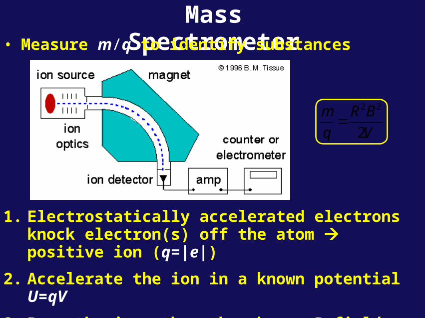
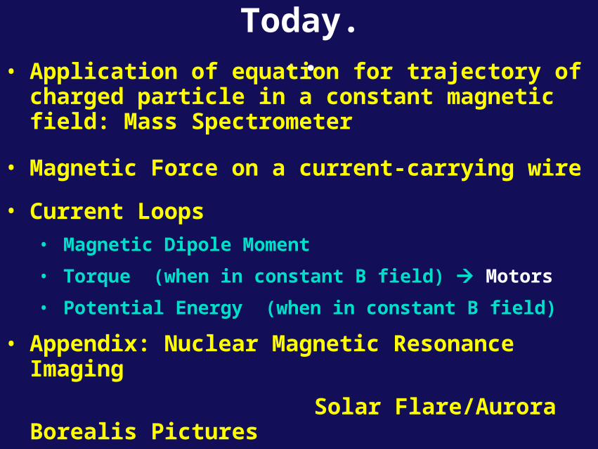
Mass Spectrometer• Measure m/q to identify substances
2 2
2
m R B
q V
1. Electrostatically accelerated electrons knock electron(s) off the atom positive ion (q=|e|)
2. Accelerate the ion in a known potential U=qV
3. Pass the ions through a known B field– Deflection depends on mass: Lighter deflects more, heavier less

Mass Spectrometer, cont.4. Electrically detect the ions which “made it through”
5. Change B (or V) and try again:
Applications: Paleoceanography: Determine relative abundances of isotopes
(they decay at different rates geological age)Space exploration: Determine what’s on the moon, Mars, etc.
Check for spacecraft leaks.Detect chemical and biol. weapons (nerve gas, anthrax, etc.).
See http://www.colby.edu/chemistry/OChem/DEMOS/MassSpec.html

Yet another example
• Measuring curvature of charged particle in magnetic field is usual method for determining momentum of particle in modern experiments: e.g.
End view: B into screen
e+
e-
B
2mv mKR
qB qB
+ charged particle
- charged particle
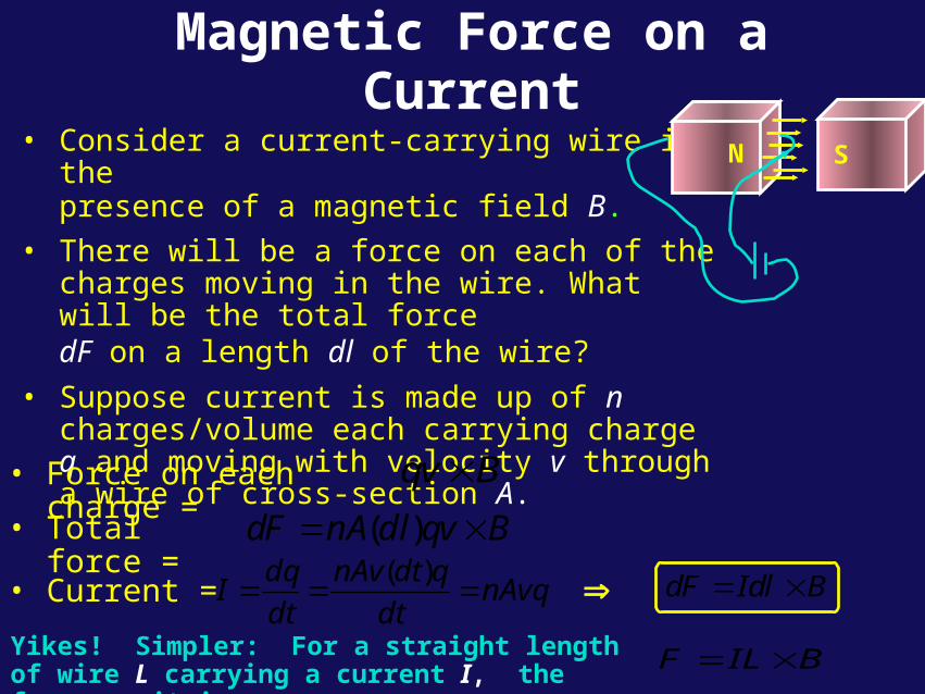
Magnetic Force on a Current
• Consider a current-carrying wire in thepresence of a magnetic field B.
• There will be a force on each of the charges moving in the wire. What will be the total forcedF on a length dl of the wire?
• Suppose current is made up of n charges/volume each carrying charge q and moving with velocity v through a wire of cross-section A.
BlIdFd
BvqdlnAFd
)(
nAvqdt
qdtnAv
dt
dqI
)(
Bvq
• Force on each charge =
• Total force =
• Current =
N S
Yikes! Simpler: For a straight length of wire L carrying a current I, the force on it is:
BLIF

Magnetic Force on a Current Loop
• Consider loop in magnetic field as on right: If field is to plane of loop, the net force on loop is 0!
• If plane of loop is not to field, there will be a non-zero torque on the loop!
B
x
.FF
x x x x x x x x x x x x x x x x x x x x x x x x x x x x x x x x x x x
B
I
F
F
FF– Force on top path cancels force
on bottom path (F = IBL)
– Force on right path cancels force on left path. (F = IBL)
1

Lecture 13, Act 1 • A current I flows in a wire which is formed in the
shape of an isosceles right triangle as shown. A constant magnetic field exists in the -z direction.
– What is Fy, net force on the wire in the y-direction?
(a) Fy < 0 (b) Fy = 0 (c) Fy > 0
x x x x xx x x x xx x x x xx x x x xx x x x xx x x x xx x x x xx x x x x
LL
L
B
x
y
2

Calculation of Torque
• Suppose the coil has width w (the side we see) and length L (into the screen). The torque is given by:
• Note: if loop B, sin = 0 = 0maximum occurs when loop parallel to B
Frτ
AIBsinF = IBL
where A = wL = area of loop
sin
22 F
wτ
r × F
F
r
B
x
.
w
F F
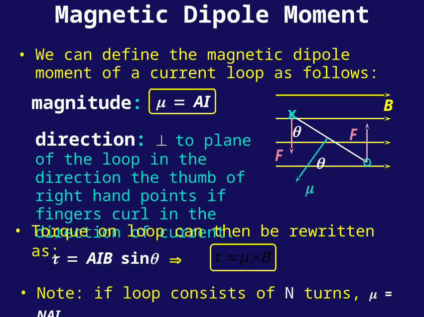
Magnetic Dipole Moment
• We can define the magnetic dipole moment of a current loop as follows:
direction: to plane of the loop in the direction the thumb of right hand points if fingers curl in the direction of current.
magnitude: AI
• Torque on loop can then be rewritten as:
• Note: if loop consists of N turns, = NAI
AIBsin Bμτ
Bx
.
F F

Bar Magnet Analogy• You can think of a magnetic dipole moment as a bar
magnet:
– In a magnetic field they both experience a torque trying to line them up with the field
– As you increase I of the loop stronger bar magnet
– N loops N bar magnets
• We will see next lecture that such a current loop does produce magnetic fields, similar to a bar magnet. In fact, atomic scale current loops were once thought to completely explain magnetic materials (in some sense they still are!).
=N
μ

Applications: Galvanometers(≡Dial Meters)
We have seen that a magnet can exert a torque on a loop of current – aligns the loop’s “dipole moment” with the field.
– In this picture the loop (and hence the needle) wants to rotate clockwise
– The spring produces a torque in the opposite direction
– The needle will sit at its equilibrium position
Current increased μ = I • Area increases Torque from B increases Angle of needle increases
Current decreased μ decreases Torque from B decreases Angle of needle decreases
This is how almost all dial meters work—voltmeters, ammeters, speedometers, RPMs, etc.

Motors
Slightly tip the loop Restoring force from the magnetic torque Oscillations
Now turn the current off, just as the loop’s μ is aligned with B Loop “coasts” around until its μ is ~antialigned with B
Turn current back on Magnetic torque gives another kick to the loop Continuous rotation in steady state
BFree rotation of spindle

Motors, continuedEven better Have the current change directions every half rotation Torque acts the entire time
Two ways to change current in loop:1. Use a fixed voltage, but change the circuit (e.g., break
connection every half cycle DC motors
2. Keep the current fixed, oscillate the source voltage AC motors
VS It
2

Lecture 13, Act 2• How can we increase the
speed (rpm) of a DC motor?2A
(a) Increase I (b) Increase B (c) Increase number of loops
B

Example: Loop in a B-FieldA circular loop has radius R = 5 cm and carries current I = 2 A in the
counterclockwise direction. A magnetic field B =0.5 T exists in the
negative z-direction. The loop is at an angle = 30 to the xy-plane.
= r2 I = .0157 Am2
What is the magnetic moment of the loop?x x x xx x x xx x x xx x x xx x x xx x x xx x x x
I
x
yB
z
y x
z
XB
X
The direction of is perpendicular to the plane of the loop as in the figure.
Find the x and z components of :
x = – sin 30 = –.0079 Am2
z = cos 30 = .0136 Am2

Electric Dipole Analogy
Frτ
Frτ
(per turn)EqF
BLIF
aqp
2 NAIμ
Epτ
Bμτ
Bx
.
E
.
+q
-qF F
F
F
p

Potential Energy of Dipole
• Work must be done to change the orientation of a dipole (current loop) in the presence of a magnetic field.
• Define a potential energy U (with zero at position of max torque) corresponding to this work.
θ
τdθU90
θ
θdθμBU90
sin
Therefore,
θθμBU 90cos θμBU cos BμU
Bx
.
F
F

Potential Energy of Dipole
B
x
Bx
B
x
= 0
U = -B
= 0
U = B
negative work positive work
=B
X
U = 0

Summary
• Mass Spectrometer• Force due to B on I
• Magnetic dipole– torque
– potential energy
• Applications: dials, motors, NMR, …• Next time: calculating B-fields from
currents
dF I dl B
AIN
B
90U B zero defined at

MRI (Magnetic Resonance Imaging) ≡ NMR (Nuclear Magnetic Resonance)
[MRI invented by UIUC Chem. Prof. Paul Lauterbur,who shared 2003 Nobel Prize in Medicine]
A single proton (like the one in every hydrogen atom) has a charge (+|e|) and an intrinsic angular momentum (“spin”). If we (naively) imagine the charge circulating in a loop magnetic dipole moment μ.
In an external B-field:
– Classically: there will be torques unless is aligned along B or against it.
– QM: The spin is always ~aligned along B or against it
Aligned: 1U B Anti-aligned: 2U B
Energy Difference: 2 1 2U U U B

MRI / NMR Example
262 2.82 10 JU B
26
-34
2.82 10 J42.5 MHz
6.63 10 J sf
Aligned: 1U B Anti-aligned: 2U BEnergy Difference: 2 1 2U U U B
B = 1 Tesla (=104 Gauss) (note: this is a big field!)
μproton = 1.41•10-26 Am2
In QM, you will learn that photonenergy = frequency • Planck’s constant
h ≡ 6.63•10-34 J s
What does this have to do with ?

MRI / NMR continued
If we “bathe” the protons in radio waves at this frequency, the protons can flip back and forth.
If we detect this flipping hydrogen!
The presence of other molecules can partially shield the applied B, thus changing the resonant frequency (“chemical shift”).
Looking at what the resonant frequency is what molecules are nearby.
Finally, because , if we put a strong magnetic field gradient across the sample, we can look at individual slices, with ~millimeter spatial resolution.
f U B
B
Small Blow freq.
Bigger Bhigh freq.
Signal at the right frequency only from this slice!

Solar Flare/Aurora Borealis links
http://cfa-www.harvard.edu/press/soolar_flare.mov
http://science.nasa.gov/spaceweather/aurora/gallery_01oct03_page2.html