Embed Size (px)
Citation preview

2008-9 AIAA Foundation Undergraduate Team Engine Design Competition
A Variable Cycle Engine for
Subsonic Transport Applications
- Request for Proposal -
Gas Turbine Engine Technical Committee
Air-Breathing Propulsion Integration Technical Committee High Speed Propulsion Technical Committee
May 2008

Summary The demand for reduced fuel burn and lower take-off noise is unrelenting as fuel costs are driven ever-higher by the present oil crisis and airport noise is restricted by increasingly tough legislation. In addition, atmospheric pollution – mainly in the form of emissions of oxides of nitrogen & carbon dioxide – has become an overarching environmental issue that can be addressed by burning less fuel as well asoptimizing engine performance at all segments of the mission. Variable cycle engines offer a new range of options when it comes to optimizing engine performance and minimizing noise & emissions at allsegments of an aircraft mission. A new variable engine is required to replace mid-size high bypass ratio turbofan engines in the 31,000 lbf thrust category at take-off. Details of a CFM56-5C2 mixed flow turbofan baseline engine at take-off and cruise are given. Retaining the primary cycle parameters, the VCE architecture should be used to generate a new optimum designsolution using the ability to vary the two available bypass ratios between take-off and cruise. Variation of the cooling flow rates should also be considered. In order of priority, the selection criteria for the new variable cycle engine are improved fuelconsumption, reduced environmental impact in the form of noise & emissions. The new engine should fitwithin the existing nacelle and engine mass should be minimized. Increases in acquisition & maintenance cost should be justified by improvements The overall objective is to design a viable system that incorporates new technologies, while staying withinthe geometric envelope. The level of design detail needed to demonstrate feasibility of the new propulsion system is laid out in this document. Dr. Ian Halliwell AIAA Air Breathing Propulsion Technical Group Senior Research Scientist, AVETEC Inc. May 16, 2007 e-mail:[email protected]
CONTENTS
1. Introduction 2. Current Engine 3. New Engine Requirements 4. Design Constraints & Guidelines 5. Competition Expectations References Suggested Reading Attachments
A. Engine Design Limits B. Fans & Compressors: Tip Speed vs. Stage Pressure Ratio C. Sideline Noise vs. Jet Velocity for an Untreated Conical Nozzle D. NOx Production vs. T3
Appendix 1. Letter of Intent Appendix 2.
I. Rules – General II. Copyright III. Schedule and Activity Sequences IV. Proposal Requirements V. Basis for Judging

1. Introduction In the 1960s & 70s, the quest to combine high thermal efficiency (given by a turbojet only at high turbineentry temperatures) with high propulsive efficiency (given by a turbojet only at low turbine entrytemperatures) led to the advent of the turbofan engine. The high bypass ratio turbofan has dominatedcommercial aviation ever since, owing to its ability to overcome the need for severe compromise betweentake-off and cruise operations that existed previously in a simple turbojet. The existence of the bypass stream at relatively low velocity also results in low noise at take off and this has been especially fortuitousin light of the subsequent huge expansion in civil operations from urban airports. The need to maximizethermal and propulsive efficiencies simultaneously is, of course, because their inverse product determinesspecific fuel consumption. For reference, Figure 1 shows a typical high bypass ratio turbofan engine with station numbers.
13 182 21 25
3 44144 45 5 6 8
16
31
HP leak to LPT exit
a
bc
LPT cooling
overboard bleeds
handling bleed
leakage from bypass
a HP leakage to bypassb NGV coolingc HPT cooling
Figure I. A Conventional High Bypass Ratio Turbofan Engine While modern versions of the turbofan have delivered performance and thrust-to-weight ratios that have been continually more impressive, the dichotomy between take-off and cruise operations has remained; to optimize take-off performance, sacrifices must invariably be made at cruise conditions and vice versa. Design choices are limited to what is effectively a single-point engine, optimized by compromising each of the major components and the performance at many of the operating conditions. In a fixed architecture, the compromises can only be partially mitigated by the rotational speed schedule and the useof variable stators & bleed air in the compression system. Clearly more flexibility and control are neededin the engine cycle. The demand for reduced fuel burn and lower take-off noise is unrelenting as fuel costs are driven ever-higher by the present oil crisis and airport noise is restricted by increasingly tough legislation. Inaddition, atmospheric pollution – mainly in the form of emissions of oxides of nitrogen and carbon

dioxide – has become an overarching environmental issue that can be addressed by burning less fuel aswell as optimizing engine performance at all segments of the mission. Recent European studies state quite unequivocally that the impact of pollution on the world climate is the most serious long-term threat to the continued growth of air travel. An additional conclusion is that increasing conflict is encounteredwhen environmental objectives are sought. This is exemplified by the fact that specific thrust andpropulsive efficiency may be improved by raising overall pressure ratio and turbine entry temperature butat the expense of increased NOx. The dilemma is reinforced by the conflict between local and global demands, wherein an increased bypass ratio causes lower noise and NOx at take-off but higher fuel burn and higher NOx production at cruise. While significant contributions can still be achieved via advances in fundamental technologies – lower losses, an improved combustion process, better materials, etc. – operational improvements via the engine cycle can also play an important role. Commercial aviation does not welcome extreme advances becausethe risks are usually too high, but, by no means have we exhausted the potential of what has been madeavailable to us through the development of turbofan engines to-date. Therefore, in the face of diminishing returns for investment, there is a pressing need to make the most of what we have, as the stakes and rewards for success become greater. Engine designers would like to be able to change the bypass ratio and fan pressure ratio in flight.Typically and essentially, commercial and military engines are designed for maximum thrust. Payload is driven by thrust capability. At take-off, engines accelerate very large volumes of air to relatively lowvelocities to achieve maximum thrust. This requires very high pressure ratios in the engine core and very high power internal power levels. This, in turn, leads to extremely high turbine entry temperatures.While take-off power is indeed important, this phase of almost any flight is relatively short and represents a small percentage of flight time. Most of the fuel is consumed at cruising, either subsonically (commercial applications and military transports) or supersonically (military fighters). At cruiseconditions, much lower fan pressure ratios and bypass ratios are desirable to generate the necessary thrustand to reduce drag. Unfortunately, the levels needed cannot be reached by a “dumb” engine cyclebecause it can only be rolled back in proportion to mechanical speed. Again – taking note of the technology we have to work with – fuel consumption and range are affected adversely and severely by cooling air. Since it goes around the burner, having already absorbed work from the compressor, and isnot available as “T4” gas to extract power from the cycle via the turbines, it is a tremendous penalty on cycle performance. This situation is exacerbated by the fact that as the engine speed falls off at cruise andthe working temperature is lower, the percentage cooling air is fixed! If the amount of cooling air couldbe reduced in proportion to operating conditions, fuel consumption would improve, to the benefit of specific fuel consumption and range potential. All of the above leads inexorably to intelligent variable cycle engines. Variable cycle engines (VCEs) offer a new range of options when it comes to optimizing engine performance at each segment of an aircraft mission. Such configurations are certainly not new. The VCE has been studied extensively forhigh speed applications partly because large variations in geometry must be made to accommodate theextreme variations of Mach number and fluid density through the flight spectrum. The added complexityand expense can be justified more easily in high speed civil or military applications than in the subsoniccivil arena. However, the financial, environmental and political scenarios have changed tremendously in

the past decade and serious examination of variable cycle systems for subsonic missions is now perfectlyreasonable.
Figure 2. A Generic Variable Cycle Engine with a Mixed Convergent Nozzle
Figure 2 shows a low bypass ratio, variable cycle turbofan engine with an augmenter in its mixed exhaust stream. While after-burning is certainly not practical or necessary for subsonic applications, the primary feature of interest here is the existence of two bypass streams (activated by variable bypass injectors or VABIs) that afford a high degree of cycle variability when combined with a large initial bypass ratio, typical of modern commercial engines. It is such a configuration that we wish to explore and exploit. Intelligent propulsions systems, based on variable cycle engines, will allow many future requirements to be met in both commercial and military contexts. However, significant research is still needed to achieve such far-reaching objectives. A new engine design is sought with thrust capabilities equal to those of an existing mixed flow turbofan engine currently in use. The engine we hope to replace is the CFM56-5C2. This is a mixed-flow, high bypass ratio, medium thrust turbofan currently in use on the Airbus 340-200/300, producing 31,200 lbf net thrust at standard take off conditions. The objective is to design a viable VCE system while staying within the existing envelope. Any additional weight & the obvious increased complexity should be justified on the basis of cost, performance & maintainability of the engine while meeting the mission requirements.
3 53124 25
2
64
6
16
414
4445
13
163
637
8
b handling bleedoverboard bleeds
leakage from bypass
NGVCool.
HPT coolinga leakage to bypass
21 125
225
15
HP leak to LPT exit
ba
VABI 1
LPT cooling
VABI 3
VABI 2
263
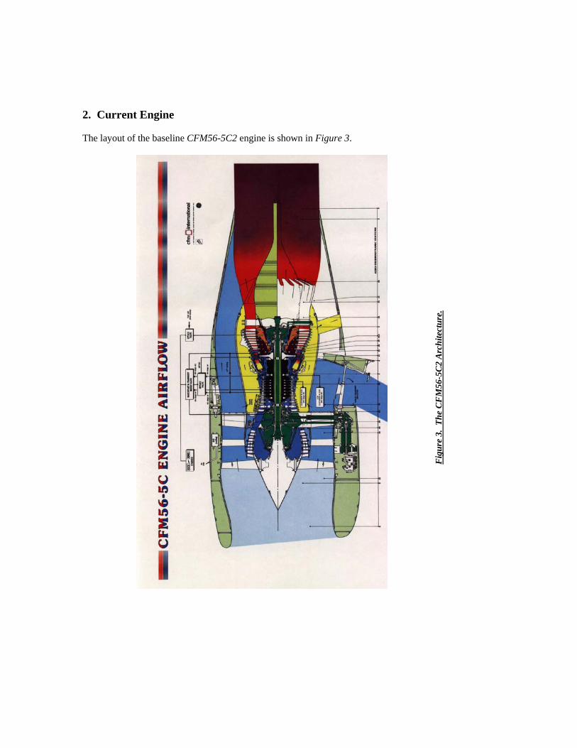
2. Current Engine The layout of the baseline CFM56-5C2 engine is shown in Figure 3.
Fig
ure
3. T
he C
FM
56-5
C2
Arc
hite
ctur
e.

Engine Type Axial, mixed-flow turbofan
Number of fan/booster/compressor stages 1, 4, 9
Number of HP/LP turbine stages 1, 5
Combustor type Annular
Maximum net thrust at sea level 31,200 lbf
Specific fuel consumption at max. power 0.32 lbm/hr/lbf
Mass flow rate1 1027 lbm/s
Overall pressure ratio at max. power1 28.4
Max. overall pressure ratio at max-climb2 37.4
T41 (hot day)2 2943 ˚R
Bypass ratio2 6.6
Max. envelope diameter1 76.6 inches
Fan diameter1 72.3 inches
Max. envelope length1.2 103 inches
Dry weight less tail-pipe1 5670 lbm
Dry weight of complete propulsion system2 8630 lbm
Applications A340-200/300
Table 1. CFM56-5C2 Engine: Basic Data on Overall Geometry, Components & Performance
Table 1 provides some basic data on overall geometry, stage counts on major components, overall mass and performance of the baseline engine. A preliminary design exercise addresses the major flowpath components only and cannot account for many additional sub-systems, nuts & bolts, seals and controls & accessories that comprise a working engine. It is this which accounts for the difference between the dryweight less tail-pipe and the dry weight of complete propulsion system in the table. It should also benoted that publicly released figures such as these frequently need careful interpretation; in the current caseyou must decide for yourself what the tailpipe consists of in order to match the mass target in your baseline engine model! Similar comments can be made about quoted lengths. In Table 1, engine length is measured from the flange just upstream of the fan face to the rear frame immediately downstream of the LP turbine. Purists should also note that usually we do not distinguish between the terms weight and massand use both to refer to mass.

Table 2. The CFM56-5C2 Cycle at Design Point Table 2 characterizes the baseline engine cycle for a primary operating point – the design point – at sea level take-off taken from a cycle simulation using the GasTurb 11 design & analysis code (Reference 3). This data is intended to provide a reasonable representation of the CFM56-5C2 cycle and is not necessarily a true & accurate simulation.

Table 3. The CFM56-5C2 Cycle at Off-Design Cruise Conditions Table 3 shows the baseline engine cycle at off-design cruise conditions (Mach 0.85, 35,000 feet). Of greatest interest is the thrust, which must be maintained by the new candidate engine, and the specific fuelconsumption, which should be improved upon, provided the thrust requirements are not increased by engine weight (See comments at the beginning of Section 3).

3. New Engine Requirements The variable engine cycle should be used to design a replacement for the CFM56-5C2 engine. This isneeded for entry into service in 2018 due to the demand for improved engine performance as reflected especially in reduced fuel consumption and lower environmental impact in the form of noise & emissions. It should be noted that low fuel burn is not necessarily related to specific fuel consumption, since if the engine mass is increased considerably to obtain the low sfc the resulting thrust requirement may be considerably higher and a greater fuel burn may be required at cruise! The power off-take of 75 hp is to be retained. Two operating conditions should be used in your design exercise; required net thrust is31,200 lbf at take-off and 7,120 lbf at cruise conditions (Mach 0.85, 35,000 feet). The generic variable cycle engine in Figure 2 has the booster (a core-driven fan) on the high-speed spool. However, it is possible to adopt the more common practice in high-bypass engines of having the booster on the low-speed spool and it is recommended that this be considered. Additional technology may be assumed to be available in the form of improved materials and component performance. In your selection of materials, you may make reasonable assumptions I regard to temperature capabilities of existing materials so that lighter ones may be used to replace those in theCFM56 baseline. In your new designs you may also assume improvements of 2% in the isentropic efficiencies of the fan, booster, compressor, HP turbine and LP turbine compared with the values given in Table 2 for the baseline engine. Alternatively you may estimate new component efficiencies if thesoftware is available to you. You should also consider the effect on engine performance of varying the % cooling air values at off-design cruise conditions. In order of priority, the selection criteria for the new variable cycle engine are:
• Improved fuel consumption • Reduced environmental impact in the form of noise & emissions
• The same nacelle size
• Low engine mass
• Acquisition & maintenance cost increases should be justified by improvements
The overall objective is to design a viable system that incorporates new technologies, while staying withinthe geometric envelope. The level of design detail needed is laid out in the following section. Additionalweight & complexity should be justified on the basis of cost, performance & maintainability of the engine and of the mission requirements.

4. Design Constraints & Guidelines Each team should select either take-off or cruise as their critical mission point at which to design their candidate engine and justify their selection. No other mission segments need to be considered in detailanalytically, but the team should give some consideration to their engine’s ability to complete the mission, with climb, descent, etc being addressed briefly for potential problems. No analysis of the airframe characteristics is required – this is an engine design study. However, if an airframe issue arises as a result of the engine design exercise it should be recognized and addressed with abrief description of actions that would need to be taken. No credit will be given for specific attention tothe airframe. Because your methods of analysis & design may differ from those used to generate the baseline dataprovided, you will need to replicate the baseline engine cycle in your own design system to form your own baseline. Your “new baseline” values may not agree precisely with those included here – nor do they need to – but you will then have an accurate means of quantifying your improvements! Different ranges of the two bypass ratios should be considered in your design study and appropriatethermodynamic cycle models should be generated. It is recommended that a design matrix should be determined, based on a limited number of combinations of the relevant major design variables. Tradestudies should then be carried out in order to select an optimum solution within each engine type. Eachdesign team should apply relevant Figures of Merit from Section 3 to determine their final design selection for the enhanced VCE engines. The new engines should be designed to a consistent set of limits and guidelines that correspond to anentry-into-service of 2018. A number of these are listed in Attachment A. It should be noted that the use of these extremes is not mandatory – they cannot be exceeded, but lower values may be employed!Teams are encouraged to research advanced engine performance goals.
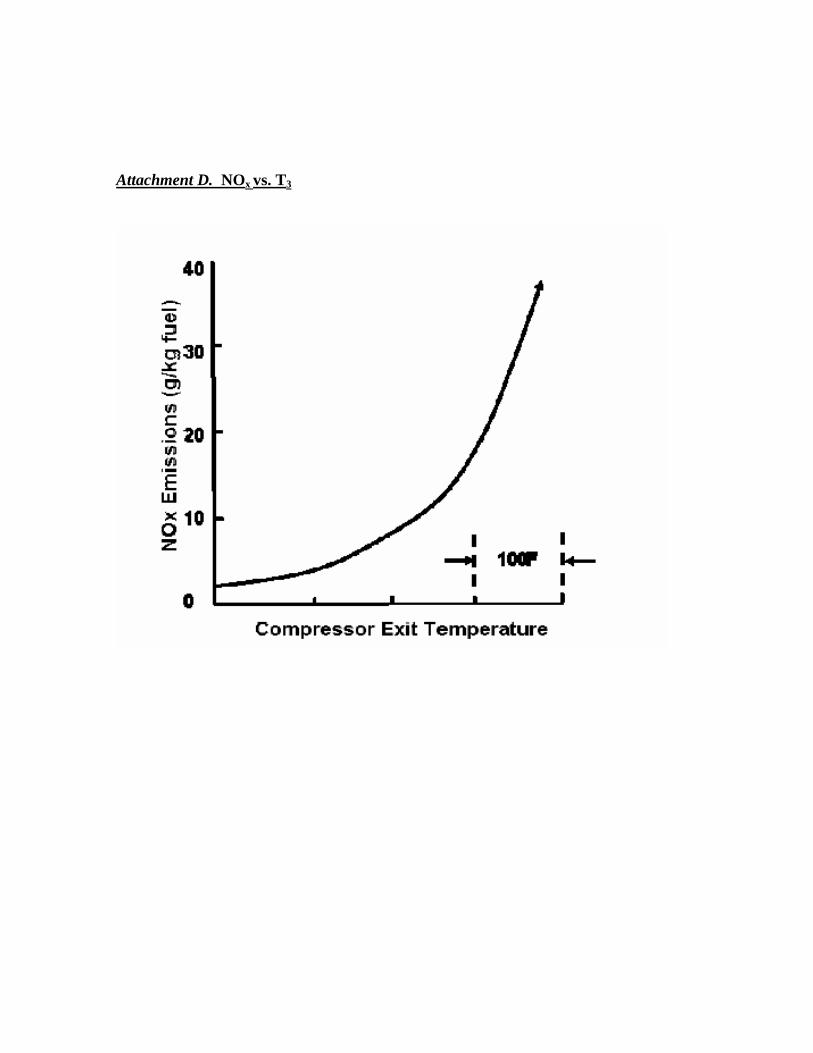
Attachment B is a correlation that indicates an empirical relationship between blade tip speeds in fans &compressors and the pressure ratio generated in a corresponding first stage. This may be used to assistwith some initial design choices and stage counts in the compression system. Environmental legislation (FAR36 Stage 3 et seq.) dictates that sideline noise at take-off should not exceed certain limits. It should be noted that sideline noise is measured with the aircraft at an altitude of689 feet and a Mach number of 0.32. These should be assumed to be relevant. Attachment C, from Reference 4, contains estimates of sideline noise at take-off as a function of the jet velocity from an untreated circular nozzle. You must determine the noise regulations for an airplane like the Airbus 340and apply them to your engine design. In the event that an engine design fails to meet this criterion,appropriate modifications must be made to the nozzle (or at least discussed) so that it produces the necessary noise suppression. Extra credit will be given for such features. There are also legislative issues to be addressed for emissions. NOx at both cruise and take-off & landing is to be minimized in addition to CO2 and unburned hydrocarbons. Attachment D shows the effects of

increasing compressor delivery temperature on the production of NOx. This has the effect of limiting the overall pressure ratio. Although, for proprietary reasons, the abscissa is not scaled, it can be assumed thatthe left hand end of the calibration corresponds roughly to “current technology”. The penalty forexceeding the current standard is very severe! In addition to the application of sophisticated advancedcombustor technology not expected to be available to student design teams, the emissions issue in general can, of course, be addressed simply by minimizing the fuel burn. 5. Competition Expectations The existing rules and guidelines for the AIAA Foundation Student Design Competition should be observed and these are supplied in Appendix 2. In addition, the following specific suggestions are offeredfor the Engine Design Competition. It is not expected that student teams produce design solutions of industrial quality, however it is hopedthat attention will be paid to the practical difficulties encountered in a real-world design situation and that these will be recognized and acknowledged. If such difficulties can be resolved quantitatively,appropriate credit will be given. If suitable design tools and/or knowledge are not available, then a qualitative description of an approach to address the issues is quite acceptable. In a preliminary engine design the following features must be provided: • Definition and justification of critical mission point(s) that drive the candidate propulsion system
design(s). • Documentation of the trade studies conducted to determine the preferred engine cycle parameters such
as fan pressure ratio, bypass ratio, overall pressure ratio, turbine inlet temperature, etc. • An engine configuration with a plot of the flowpath that shows how the major components fit
together, with emphasis on operability at different mission points. • A clear demonstration of design feasibility, with attention having been paid to technology limits. • Stage counts. • Velocity diagrams corresponding to key stages. • Blade and vane counts.

• Spanwise distributions of flow properties with appropriate consideration of radial equilibrium. This is
not required for all stages, but key examples should be chosen for consideration of tip speed & hub reaction, for example.
• Estimates of component performance and overall engine performance to show that the assumptions
made in the cycle have been achieved. • In preliminary design, trends are more important than absolute values. This is particularly relevant
when it comes to engine weight and costs. We are looking for an optimum solution selected from amatrix of possible candidates.
While only the preliminary design of major components in the engine flowpath is expected to be addressed quantitatively in the proposals, it is intended that the role of secondary systems such as fuel & lubrication be given serious consideration in terms of modifications and how they would be integrated into the new engine design. Credit will be given for clear descriptions of how any appropriate upgradeswould be incorporated and how they would affect the engine cycle. Each proposal should also contain a brief discussion of any computer codes or Microsoft Excelspreadsheets used to perform engine design & analysis, with emphasis on any additional special featuresgenerated by the team. Questions will be taken by volunteers from the AIAA Air Breathing Propulsion Technical Committee, whose contact information will be provided to teams who register officially.

References 1. “Aerospace Source Book”. Aviation Week & Space Technology. January 15, 2007. 2. “CFM Executive Summary”. CFM International. c. 1990. 3. “GasTurb 11: A Design & Off-Design Performance Program for Gas Turbines” Joachim Kurzke. 2007. 4. “Noise Suppression Nozzles for a Supersonic Business Jet” James R. Stone, Eugene A. Krejsa, Ian Halliwell & Bruce J. Clark. AIAA-2000-3194. 36th AIAA/ASME/SAE/ASEE Joint Propulsion Conference, Huntsville, AL. 2000.
Suggested Reading
1. “Gas Turbine Theory” H.I.H Saravanamuttoo, G.F.C Rogers &.H. Cohen, Prentice Hall. 5th Edition 2001. 2. “Elements of Propulsion – Gas Turbines and Rockets” J.D. Mattingly. AIAA Education Series. 2006. 3. “Jet Propulsion” N. Cumpsty. Cambridge University Press. 2000. 4. “Gas Turbine Performance” P. Walsh & P. Fletcher. Blackwell/ASME Press. 2nd Edition, 2004. 5. “Fundamentals of Jet Propulsion with Applications” Ronald D. Flack Cambridge University Press. 2005 6. “Principles of Turbomachinery in Air-Breathing Engines” Erian A. Baskharone Cambridge University Press. 2006

Attachment A. Design Limits
1 ψ = Δh/2Um
2, where Um is mean blade speed 1 Dimensions of AN2 are inches2 × rpm2
Parameter Design Limit Compressor Maximum specific flow 42.0 lbm/ft2 Maximum compressor delivery temperature, T3 1250 °F Maximum tip speed 1800 ft/s Maximum exit radius ratio (rhub/rtip) 0.935 Minimum stall margin 20 %
High Pressure Turbine Maximum temperature at first rotor leading edge,T41 2950 °F Maximum stage loading coefficient (ψ)1 1.2 Maximum blade hub turning angle (Δβ) 134 ° Maximum relative exit Mach number 1.2 Minimum stage reaction at hub 15 % Maximum AN2 at exit1 60 × 109
Power Turbine Maximum stage loading coefficient (ψ) 1.0 Maximum absolute exit Mach number 0.6 Maximum relative exit Mach number 1.0 Maximum mean exit swirl angle 30 ° Maximum AN2 at exit 55 × 109 Minimum stage reaction at hub 15 % Minimum exit radius ratio (rhub/rtip) 0.6

Attachment B. Fans & Compressors: Tip Speed vs. Stage Pressure Ratio
Tip Speed Trends
0
200
400
600
800
1000
1200
1400
1600
1800
2000
1 1.1 1.2 1.3 1.4 1.5 1.6 1.7 1.8 1.9 2
Pressure Ratio, stage 1
Cor
rect
ed T
ip S
peed
(fps
)
Fans LPC's HPC's Wate Manual

Attachment C. Sideline Noise vs. Jet Velocity for an Untreated Conical Nozzle
Attachment D. NOx vs. T3

Appendix 1. Letter of Intent
2008/2009 AIAA Foundation
Undergraduate Team Engine Design Competition Request for Proposal: A Variable Cycle Engine for Subsonic Transport Applications.
Title of Design Proposal: _________________________________________________________ Name of School: _______________________________________________________________ Designer’s Name AIAA Member # Graduation Date Degree ______________________ ______________ ______________ _________________ Team Leader Team Leader E-mail ________________________ ________________ ________________ ___________________
________________________ ________________ ________________ ___________________
________________________ ________________ ________________ ___________________
________________________ ________________ ________________ ___________________
________________________ ________________ ________________ ___________________
________________________ ________________ ________________ ___________________
________________________ ________________ ________________ ___________________
________________________ ________________ ________________ ___________________
________________________ ________________ ________________ ___________________
In order to be eligible for the 2008/2009 AIAA Undergraduate Team Engine Design Competition, you must complete this form and return it to the AIAA Director of Student Programs before 13 March 2009, at AIAA Headquarters, along with a one-page “Letter of Intent” as noted in Section II, “Schedule and Activity Sequences.” For any nonmember listed above, a student member application and member dues payment should also be included with this form.
Signature of Faculty Advisor Signature of Project Advisor Date
Faculty Advisor – Printed Project Advisor – Printed Date

Appendix 2. I. Rules – General 1. All undergraduate AIAA branch or at-large Student Members are eligible and encouraged to participate. 2. An electronic copy of the report in MS Word or Adobe PDF format must be submitted on a CD or DVD to AIAA Student Programs. Total size of the file(s) cannot exceed 60 MB. A “Signature” page must be included in the report and indicate all participants, including faculty and project advisors, along with their AIAA member numbers. Designs that are submitted must be the work of the students, but guidance may come from the Faculty/Project Advisor and should be accurately acknowledged. 3. Design projects that are used as part of an organized classroom requirement are eligible and encouraged for competition. 4. The prizes shall be: First place-$2,500; Second place-$1,500; Third place-$1,000 (US dollars). Certificates will be presented to the winning design teams for display at their university and a certificate will also be presented to each team member and the faculty/project advisor. One representative from the first place design team may be expected to present a summary design paper at an AIAA Conference in2009. Reasonable airfare and lodging will be defrayed by the AIAA for the team representative 5. More than one design may be submitted from students at any one school. Projects should be no more than 100 (total) double-spaced typewritten pages and typeset should be no smaller than 10pt Times(including graphs, drawings, photographs, and appendix) on 8.5” x 11.0” paper. Up to five of the 100 pages may be foldouts (11” x 17” max). 6. If a design group withdraws their project from the competition, the team chairman must notify AIAA Headquarters immediately! 7. Team competitions will be groups of not more than ten AIAA branch or at-large Student Members per entry. Individual competitions will consist of only 1 AIAA branch or at-large Student Member per entry. II. Copyright All submissions to the competition shall be the original work of the team members. Any submission that does not contain a copyright notice shall become the property of AIAA. A team desiring to maintain copyright ownership may so indicate on the signature page but nevertheless, by submitting a proposal, grants an irrevocable license to AIAA to copy, display, publish, and distribute the work and to use it for all of AIAA’s current and future print and electronic uses (e.g. “Copyright © 20__ by _____. Published by the American Institute of Aeronautics and Astronautics, Inc., with permission.).
Con formato: Numeración yviñetas

Any submission purporting to limit or deny AIAA licensure (or copyright) will not be eligible for prizes. III. Schedule & Activity Sequences Significant activities, dates, and addresses for submission of proposal and related materials are as follows: A. Letter of Intent – 13 Mar 2009 B. Receipt of Proposal – 12 June 2009 C. Announcement of Winners – Aug 2009 Groups intending to submit a proposal must submit a one page Letter of Intent along with the signed attached Intent Form (Item A) on or before the date specified above, at the following address:
AIAA Student Programs 1801 Alexander Bell Drive Suite 500 Reston, VA 20191-4344
The CD containing the finished proposal must be received at the same address on or before the date specified above for the Receipt of Proposal (Item B).
IV. Proposal Requirements The technical proposal is the most important factor in the award of a contract. It should be specific and complete. While it is realized that all of the technical factors cannot be included in advance, the following should be included and keyed accordingly: 1. Demonstrate a thorough understanding of the Request for Proposal (RFP) requirements. 2. Describe the proposed technical approaches to comply with each of the requirements specified in the RFP, including phasing of tasks. Legibility, clarity, and completeness of the technical approach areprimary factors in evaluation of the proposals. 3. Particular emphasis should be directed at identification of critical, technical problem areas.Descriptions, sketches, drawings, systems analysis, method of attack, and discussions of new techniques should be presented in sufficient detail to permit engineering evaluation of the proposal. Exceptions to proposed technical requirements should be identified and explained. 4. Include tradeoff studies performed to arrive at the final design. 5. Provide a description of automated design tools used to develop the design.

V. Basis for Judging 1. Technical Content (35 points) This concerns the correctness of theory, validity of reasoning used, apparent understanding and grasp of the subject, etc. Are all major factors considered and a reasonably accurate evaluation of these factors presented? 2. Organization and Presentation (20 points) The description of the design as an instrument of communication is a strong factor on judging. Organization of written design, clarity, and inclusion of pertinent information are major factors. 3. Originality (20 points) The design proposal should avoid standard textbook information, and should show the independence of thinking or a fresh approach to the project. Does the method and treatment of the problem showimagination? Does the method show an adaptation or creation of automated design tools. 4. Practical Application and Feasibility (25 points) The proposal should present conclusions or recommendations that are feasible and practical, and not merely lead the evaluators into further difficult or insolvable problems.


![Notes 180821 135259 5c2[16298]](https://img.dokumen.tips/doc/110x75/62a909c6561a9b56cf33b031/notes-180821-135259-5c216298.jpg)