Embed Size (px)
Citation preview
HT#
059
103-
00 B
Warningall Heat-Timer controls and valves are strictly operating controls and
valves; they should never be used as a primary limit or safety control. all equipment must have its own certified limit and safety controls required
by local codes. The installer must verify proper operation and correct any safety problems prior to the installation of any Heat-Timer equipment.
installation and Operation Manual
Motorized Valvesfor Steam and Hot Water Heating Systems
2-Way and 3-Way Motorized Valves
2 2-Way and 3-Way Motorized Valve installation Manual
HT#
059
103-
00 B
Contents
applications. . . . . . . . . . . . . . . . . . . . . . . . . . . . . . . . . . . . . . . . . . . . 3Hot Water Heating Applications 3Steam Heating Applications 3Steam to Hot Water Heating Applications 3
installation: . . . . . . . . . . . . . . . . . . . . . . . . . . . . . . . . . . . . . . . . . . . . 3Components 3Mounting 4Valve Actuator Assembly 4Flow Direction 5Actuator Manual Operation 5Actuator LED 5
Wiring . . . . . . . . . . . . . . . . . . . . . . . . . . . . . . . . . . . . . . . . . . . . . . . 6Wiring the Actuator to the MPC Platinum Control 6Wiring to the HWR Platinum Control 7Wiring the Actuator to the HWE-MOV or MCF Elite Controls 8Piping 2-Way Motorized Valve in One-Pipe Steam Heating Application 9Piping 2-Way Motorized Valve in Two-Pipe Steam Heating Application 10Piping 3-Way Motorized Valve in Hot Water Heating Application 11Piping 2-Way Motorized Valve in Steam to Hot Water Heating Application 12
Valves Sizing . . . . . . . . . . . . . . . . . . . . . . . . . . . . . . . . . . . . . . . . . . . 132-Way Steam Valve Sizing 133-Way Water Valve Sizing 14
Troubleshooting . . . . . . . . . . . . . . . . . . . . . . . . . . . . . . . . . . . . . . . . . 15Actuator Specifications 152-Way Valve Specifications 153-Way Valve Specifications 15

2-Way and 3-Way Motorized Valve installation Manual 3
HT#
059
103-
00 B
applicationsHot Water Heating applicationsThe 3-Way floating Motorized Mixing Valves are used to regulate the temperature of the water in Hydronic heating applications. They are used with Outdoor Reset or Set Point hot water heating controls (used with Heat-Timer HWR Platinum, HWE-MOV, and MCF controls). Also, they benefit two temperature systems by reducing the water temperature in the secondary loop as in snow melt applications (used with Heat-Timer SMC and RSM controls). In addition, they are used to regulate the boiler return temperature by mixing the boiler supply with the cooler return to protect boilers from condensation (used with Heat-Timer MCF controls).
Steam Heating applicationsThe 2-Way Floating Motorized Valves are used to modulate or turn on or off the steam to a building or process applications. They are used with Heat-Timer steam heating controls (MPC Platinum).
Steam to Hot Water Heating applicationsThe 2-Way Floating Motorized Valves can also be used to regulate the amount of steam entering a steam-to-hot-water heat-exchanger. This configuration is designed to control the temperature of the water in hydronic heated buildings using a steam boiler. It is used with Outdoor Reset or Set Point hot water heating controls (used with Heat-Timer HWR Platinum, HWE-MOV, and MCF controls).
installation:ComponentsA Valve and actuator are usually shipped in different crates or boxes. The following components are shipped per the following packing lists: ValVe PaCkage: aCTuaTOr PaCkage:• Valve • Actuator• Actuator Valve Adaptor• Adaptor Locknut
• Actuator Linkage Bracket (with two hex screws and two nuts
• Hex Wrench (#5)• 24 VAC Transformer
Actuator ManualOperation
Actuator LinkageBracket
Valve
Actuator ValveAdaptor
Adaptor Locknut
Power Switch
StemAttachment

4 2-Way and 3-Way Motorized Valve installation Manual
HT#
059
103-
00 B
Mounting• To avoid valve problems, all dirt, metal shavings, debris, etc...
located inside of piping must be removed / flushed out prior to installing the valve.
• The preferred installation of the valve stem and actuator is upright. However, where space restrictions dictate, the valve assembly can be mounted diagonally.
• The installation should account for an additional clearance of 4 to 6” above the actuator. This space is needed for the manual operation of the actuator. See "Actuator Manual Operation" on page 5
WarningMotorized Valves MuST nOT be installed
upside down or horizontally
Valve actuator assembly• For smaller valves, it is usually easier to assemble the
valve and actuator before the installation of the valve.• For larger valves, install the valve in position
prior to installing the actuator.• Thread and tighten the Actuator Valve Adaptor to the valve.• Remove the Actuator Brass Brackets. This
should release the Stem Attachment.• Thread the Stem Attachment to the Valve Stem. Make
sure that it is tightened against the Stem Nut.• Mount the Actuator on top of the Valve.• Thread the Adaptor Locknut to the Actuator Valve Adaptor. Make
sure that the locknut’s beveled surface is facing the valve.• Manually close or open the actuator to bring the Stem
Attachment to meet the bottom of the Actuator Shaft. See "Actuator Manual Operation" on page 5
• Join the Stem Attachment and the Actuator Shaft using the Actuator Brass Bracket. Make sure the Actuator Brass Bracket internal shape fits and locks Stem Attachment and Actuator Shaft securely.
• For proper Actuator Brass Bracket operation, its protrusions must be at the bottom (closer to the valve).
Actuator Valve Adaptor
Actuator Brass Bracket
Stem Attachment
Stem Nut
Adaptor Locknut
Stem
Actuator Shaft
Protrusion mustbe at bottom
OKOK
OK
OKOK
OK

2-Way and 3-Way Motorized Valve installation Manual 5
HT#
059
103-
00 B
Flow Direction2-Way Valves:Actuator Shaft moving Down will close the valve. Actuator Shaft moving Up will open the valve.
3-Way Valves: Actuator Shaft moving Down will close the valve hot water Port B. Thus, more cold water will pass.Actuator Shaft moving Up will close the valve cold water port A. Thus, more hot water will pass.
Flow
Down
Valve Closes
Flow
Up
Valve Opens
2-Way Single-Seat
Flow
Down
Valve Closes
Flow
Up
Valve Opens
2-Way Single-Seat
Down
Valve Closes
Up
Valve Opens
2-Way Double-Seat
Flow Flow
Up
Valve OpensOnly Hot Water
Passes
Down
Valve ClosesOnly Cold Water
Passes
A(U)
AB(C)
B(L)
A(U)
AB(C)
B(L)
3-Way Mixing
Flow
Down
Valve Closes
Flow
Up
Valve Opens
2-Way Single-Seat
Flow
Down
Valve Closes
Flow
Up
Valve Opens
2-Way Single-Seat
Down
Valve Closes
Up
Valve Opens
2-Way Double-Seat
Flow Flow
actuator Manual OperationThe actuator red top handle is used to operate the valve manually in periods of no power or when servicing the equipment.• First, make sure that the Power Switch is turned Off prior to operating the actuator
manually.• Pull the Crank Handle out and press it down to move the Actuator Shaft.• Turn the Crank Handle clockwise to move the Actuator Shaft down. Turn the
Crank Handle counter-clockwise to move the Actuator Shaft up.
1) Turn Power Switch Off
2) Pull Crank Handle Out
3) Press Down and Turn
actuator leDThe actuator has two LEDs. • A Green LED that lights when the actuator is moving its shaft downward. It is
labeled Down Limit. • A Red LED that lights when the actuator is moving its shaft upward. It is labeled
Up Limit.
1 2 3 16 17
1 2 3 16 17
Up Limit
Down Limit

6 2-Way and 3-Way Motorized Valve installation Manual
HT#
059
103-
00 B
Wiring• The Heat-Timer Motorized Valve can be used with virtually any floating motor controller. However, it is designed to work with
Heat-Timer controls.• The valve actuator uses a floating type signal (R. W. B.).• The Actuator must be powered using the provided 24 VAC transformer. A single transformer can only power a single actuator.• Remove the Red Actuator cover to reveal the wiring terminals.• Select one of the wiring options based on the control used.• After finalizing the wiring, reinstall the actuator Red cover.
Wiring the actuator to the MPC Platinum Control• Wire one of the 24VAC transformer outputs to the Actuator (1) Common terminal.• Wire the second 24VAC transformer output to the MPC Platinum (5) Common output terminal.• Connect the MPC Platinum (6) output terminal to the Actuator (2) Close terminal.• Connect the MPC Platinum (4) output terminal to the Actuator (3) Open terminal.
1 2 3 16 17
1 2 3 16 17
Up Limit
Down Limit
1 2 3 16 17
Com
mon
Clo
se
Ope
n
Clo
se L
imit
Ope
n L
imit
MPCPlatinum
MADE IN U.S.A.
PREV.(DEL)
SAFETYGROUNDMUST BE
CONNECTED
OUTTEMP
AUXINPUT 0
AUXTEMP 0
AUXTEMP 1
MENU FUNCTIONS
SELECT enters menus or accepts changes
ADJUST selects menu items or changes settings
BACK returns to previous menu
DAY selects next day
PREV./NEXT steps through output status
LIN
E
NE
UTR
AL
DAYHELP NEXT
PRESS TOSELECT
BACK
MON 12/28/04 10:43Am
ADJUST
A1
A2
A3
A4
A5
A6
A7
A8
A9
A10
A11
A12
AUXTEMP 2
DO NOT APPLY ANY VOLTAGETO SENSOR TERMINALS
A13
A14
A15
A16
A17
A18
NETWORK
PROVE
SHUTDOWN
SYSTEMTEMP
AUTO
BYPASS
ALL SENSORS MUST BEGOLD SERIES SENSORS
INPUTS
ROUTE SENSOR AND AUXILIARY WIRESTHROUGH THIS KNOCKOUT ONLY
SYSAUX
CLOCKOPTION
1OPTION
2
T
T
T
Cycle On
Cut= 55oF Day
OD= 31oF SYS= 148oF
OUTPUT
B BURNERMOTORIZED
VALVE
SYSTEM OPTION1
OPTION2
OPTION3
AUXCLOCK
T
TC O R P O R A T I O N
R
2 3 4 5 6 7 8 9 11 12 13 14 15 16 17
OUTPUT RATINGS:120VAC, 6A RESISTIVE1A PILOT DUTY15A TOTALFOR ALL CIRCUITS
INPUT RATINGS:115VAC 60Hz30VA MAX
USE COPPER WIRE,CLASS 1 WIRE ONLY
ENCLOSEDENERGY
MANAGEMENTEQUIPMENT
LISTED99RA
OPTION3
10 18
R W
120VAC
2-Way and 3-Way Motorized Valve installation Manual 7
HT#
059
103-
00 B
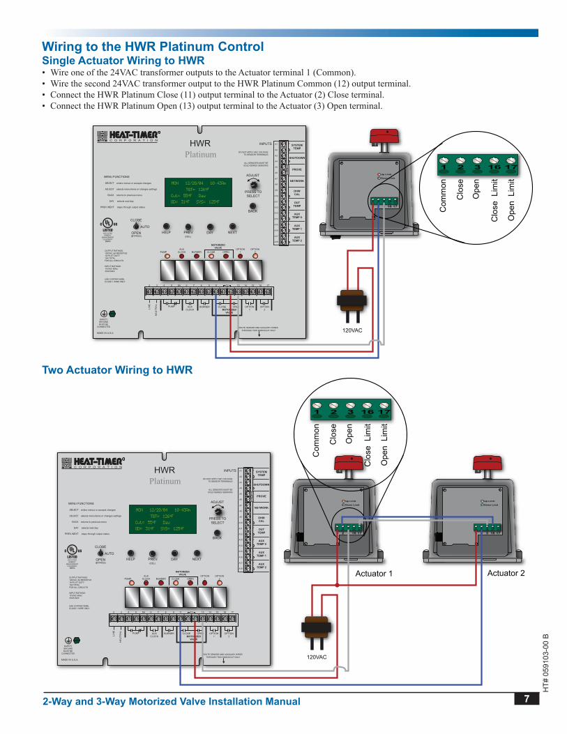
Wiring to the HWr Platinum ControlSingle actuator Wiring to HWr• Wire one of the 24VAC transformer outputs to the Actuator terminal 1 (Common).• Wire the second 24VAC transformer output to the HWR Platinum Common (12) output terminal.• Connect the HWR Platinum Close (11) output terminal to the Actuator (2) Close terminal.• Connect the HWR Platinum Open (13) output terminal to the Actuator (3) Open terminal.
1 2 3 16 17
1 2 3 16 17
Up Limit
Down Limit
1 2 3 16 17
Com
mon
Clo
se
Ope
n
Clo
se L
imit
Ope
n L
imit
HWRPlatinum
MADE IN U.S.A.
PREV.(DEL)
SAFETYGROUNDMUST BE
CONNECTED
OUTTEMP
DHWCAL
AUXTEMP 0
AUXTEMP 1
MENU FUNCTIONS
SELECT enters menus or accepts changes
ADJUST selects menu items or changes settings
BACK returns to previous menu
DAY selects next day
PREV./NEXT steps through output status
PUMP
LIN
E
NE
UTR
AL
DAYHELP NEXT
PRESS TOSELECT
BACK
MON 12/28/04 10:43Am
ADJUST
A1
A2
A3
A4
A5
A6
A7
A8
A9
A10
A11
A12
AUXTEMP 2
DO NOT APPLY ANY VOLTAGETO SENSOR TERMINALS
A13
A14
A15
A16
A17
A18
NETWORK
PROVE
SHUTDOWN
SYSTEMTEMP
CLOSE
OPEN(BYPASS)
ALL SENSORS MUST BEGOLD SERIES SENSORS
INPUTS
ROUTE SENSOR AND AUXILIARY WIRESTHROUGH THIS KNOCKOUT ONLY
BURNER
MOTORIZEDVALVE
CLOSE OPENOPTION
1OPTION
2
T
T
T
TGT= 126oF
Cut= 55oF Day
OD= 31oF SYS= 125oF
AUTO
AUXCLOCK
PUMP BURNERMOTORIZED
VALVE
CLOSE OPEN OPTION1
OPTION2
AUXCLOCK
T
TC O R P O R A T I O N
R
2 3 4 5 5A 6 7 8 9 11 12 13 14 15 16 17
OUTPUT RATINGS:120VAC, 6A RESISTIVE1A PILOT DUTY15A TOTALFOR ALL CIRCUITS
INPUT RATINGS:115VAC 60Hz30VA MAX
USE COPPER WIRE,CLASS 1 WIRE ONLY
ENCLOSEDENERGY
MANAGEMENTEQUIPMENT
99RA
120VAC
Two actuator Wiring to HWr
1 2 3 16 17
1 2 3 16 17
Up Limit
Down Limit
1 2 3 16 17
1 2 3 16 17
Up Limit
Down Limit
Actuator 1 Actuator 2
1 2 3 16 17
Com
mon
Clo
se
Ope
n
Clo
se L
imit
Ope
n L
imit
HWRPlatinum
MADE IN U.S.A.
PREV.(DEL)
SAFETYGROUNDMUST BE
CONNECTED
OUTTEMP
DHWCAL
AUXTEMP 0
AUXTEMP 1
MENU FUNCTIONS
SELECT enters menus or accepts changes
ADJUST selects menu items or changes settings
BACK returns to previous menu
DAY selects next day
PREV./NEXT steps through output status
PUMP
LIN
E
NE
UTR
AL
DAYHELP NEXT
PRESS TOSELECT
BACK
MON 12/28/04 10:43Am
ADJUST
A1
A2
A3
A4
A5
A6
A7
A8
A9
A10
A11
A12
AUXTEMP 2
DO NOT APPLY ANY VOLTAGETO SENSOR TERMINALS
A13
A14
A15
A16
A17
A18
NETWORK
PROVE
SHUTDOWN
SYSTEMTEMP
CLOSE
OPEN(BYPASS)
ALL SENSORS MUST BEGOLD SERIES SENSORS
INPUTS
ROUTE SENSOR AND AUXILIARY WIRESTHROUGH THIS KNOCKOUT ONLY
BURNER
MOTORIZEDVALVE
CLOSE OPENOPTION
1OPTION
2
T
T
T
TGT= 126oF
Cut= 55oF Day
OD= 31oF SYS= 125oF
AUTO
AUXCLOCK
PUMP BURNERMOTORIZED
VALVE
CLOSE OPEN OPTION1
OPTION2
AUXCLOCK
T
TC O R P O R A T I O N
R
2 3 4 5 5A 6 7 8 9 11 12 13 14 15 16 17
OUTPUT RATINGS:120VAC, 6A RESISTIVE1A PILOT DUTY15A TOTALFOR ALL CIRCUITS
INPUT RATINGS:115VAC 60Hz30VA MAX
USE COPPER WIRE,CLASS 1 WIRE ONLY
ENCLOSEDENERGY
MANAGEMENTEQUIPMENT
99RA
120VAC

8 2-Way and 3-Way Motorized Valve installation Manual
HT#
059
103-
00 B
Wiring the actuator to the HWe-MOV or MCF elite ControlsSingle actuator Wiring to HWe-MOV or MCF• Wire one of the 24VAC transformer outputs to the Actuator terminal 1 (Common).• Wire the second 24VAC transformer output to the HWE-MOV or MCF Elite Red wire.• Connect the HWE-MOV or MCF Elite Blue wire to the Actuator (2) Close terminal.• Connect the HWE-MOV or MCF Elite White wire to the Actuator (3) Open terminal.
1 2 3 16 17
1 2 3 16 17
Up Limit
Down Limit
1 2 3 16 17
Com
mon
Clo
se
Ope
n
Clo
se L
imit
Ope
n L
imit
120VAC
SET
®
C O R P O R A T I O N
R
SYSTEM = 147F
TARGET = 150F
SystemOpenCloseWhite (Open)
Blue (Close)
Red (Common)
Two actuator Wiring to HWe-MOV or MCF
1 2 3 16 17
1 2 3 16 17
Up Limit
Down Limit
1 2 3 16 17
1 2 3 16 17
Up Limit
Down Limit
Actuator 1 Actuator 2
1 2 3 16 17
Com
mon
Clo
se
Ope
n
Clo
se L
imit
Ope
n L
imit
120VAC
SET
®
C O R P O R A T I O N
R
SYSTEM = 147F
TARGET = 150F
SystemOpenCloseWhite (Open)
Blue (Close)
Red (Common)

2-Way and 3-Way Motorized Valve installation Manual 9
HT#
059
103-
00 B
MP
CPl
atin
um
PR
EV.
(DE
L)
OU
TTE
MP
AU
XIN
PUT
0
AU
XTE
MP
0
AU
XTE
MP
1
ME
NU
FU
NC
TIO
NS
SE
LEC
Ten
ters
men
us o
r acc
epts
cha
nges
AD
JUS
Tse
lect
s m
enu
item
s or
cha
nges
set
tings
BA
CK
retu
rns
to p
revi
ous
men
u
DAY
sel
ects
nex
t day
PR
EV.
/NE
XT
ste
ps th
roug
h ou
tput
sta
tus
LINE
NEUTRAL
DAY
HE
LPN
EX
T
PR
ES
S T
OS
ELE
CT
BA
CK
MON 12/28/04 10:43Am
AD
JUS
T
A1
A2
A3
A4
A5
A6
A7
A8
A9
A10
A11
A12
AU
XTE
MP
2
DO
NO
T A
PP
LY A
NY
VO
LTA
GE
TO S
EN
SO
R T
ER
MIN
ALS
A13
A14
A15
A16
A17
A18
NET
WO
RK
PRO
VE
SHU
TDO
WN
SYST
EMTE
MP
AU
TO
BY
PAS
S
ALL
SE
NS
OR
S M
US
T B
EG
OLD
SE
RIE
S S
EN
SO
RS
INP
UTS
RO
UTE
SE
NS
OR
AN
D A
UX
ILIA
RY
WIR
ES
THR
OU
GH
TH
IS K
NO
CK
OU
T O
NLY
SY
SA
UX
CLO
CK
OP
TIO
N1
OP
TIO
N2
T T T
Cycle On
Cut= 55oF Day
OD= 31oF SYS= 148oF
OU
TPU
T
BB
UR
NE
RM
OTO
RIZ
EDVA
LVE
SY
STE
MO
PTI
ON
1O
PTI
ON
2O
PTI
ON
3A
UX
CLO
CK
TTC
O
R
P
O
R
A
T
I
O
N
R
23
45
67
89
1112
1314
1516
17
OP
TIO
N3
1018
RW
Sys
tem
Sen
sor
Inst
alle
d on
Dry
Ret
urn
Abo
veW
ater
Lin
e
Out
door
Sen
sor
2-W
ayM
otor
ized
Valv
e
MPC
Plat
inum
Zone
A
Boi
ler W
ater
Lin
e
Boi
ler
Zone
B
Zone
C
Pipi
ng D
iagr
ams
Pipi
ng 2
-Way
Mot
oriz
ed V
alve
in O
ne-P
ipe
Stea
m H
eatin
g a
pplic
atio
n
Wa
rn
ing
2-W
ay v
alve
s m
ust b
e in
stal
led
on a
hor
izon
tal p
ipe
only
. it
mus
t not
be
inst
alle
d on
a v
ertic
al p
ipe.
The
act
uato
r ins
talla
tion
mus
t be
high
er th
an th
e va
lve.
See
"Flo
w D
irect
ion"
on
page
5

10 2-Way and 3-Way Motorized Valve installation Manual
HT#
059
103-
00 B
Wa
rn
ing
2-W
ay v
alve
s m
ust b
e in
stal
led
on a
hor
izon
tal p
ipe
only
. it
mus
t not
be
inst
alle
d on
a v
ertic
al p
ipe.
The
act
uato
r ins
talla
tion
mus
t be
high
er th
an th
e va
lve.
See
"Flo
w D
irect
ion"
on
page
5
MP
CPl
atin
um
PR
EV.
(DE
L)
OU
TTE
MP
AU
XIN
PUT
0
AU
XTE
MP
0
AU
XTE
MP
1
ME
NU
FU
NC
TIO
NS
SE
LEC
Ten
ters
men
us o
r acc
epts
cha
nges
AD
JUS
Tse
lect
s m
enu
item
s or
cha
nges
set
tings
BA
CK
retu
rns
to p
revi
ous
men
u
DAY
sel
ects
nex
t day
PR
EV.
/NE
XT
ste
ps th
roug
h ou
tput
sta
tus
LINE
NEUTRAL
DAY
HE
LPN
EX
T
PR
ES
S T
OS
ELE
CT
BA
CK
MON 12/28/04 10:43Am
AD
JUS
T
A1
A2
A3
A4
A5
A6
A7
A8
A9
A10
A11
A12
AU
XTE
MP
2
DO
NO
T A
PP
LY A
NY
VO
LTA
GE
TO S
EN
SO
R T
ER
MIN
ALS
A13
A14
A15
A16
A17
A18
NET
WO
RK
PRO
VE
SHU
TDO
WN
SYST
EMTE
MP
AU
TO
BY
PAS
S
ALL
SE
NS
OR
S M
US
T B
EG
OLD
SE
RIE
S S
EN
SO
RS
INP
UTS
RO
UTE
SE
NS
OR
AN
D A
UX
ILIA
RY
WIR
ES
THR
OU
GH
TH
IS K
NO
CK
OU
T O
NLY
SY
SA
UX
CLO
CK
OP
TIO
N1
OP
TIO
N2
T T T
Cycle On
Cut= 55oF Day
OD= 31oF SYS= 148oF
OU
TPU
T
BB
UR
NE
RM
OTO
RIZ
EDVA
LVE
SY
STE
MO
PTI
ON
1O
PTI
ON
2O
PTI
ON
3A
UX
CLO
CK
TTC
O
R
P
O
R
A
T
I
O
N
R
23
45
67
89
1112
1314
1516
17
OP
TIO
N3
1018
RW
Sys
tem
Sen
sor
Inst
alle
d on
Dry
Ret
urn
Abo
veW
ater
Lin
e
Out
door
Sen
sor
2-W
ayM
otor
ized
Valv
e
MPC
Plat
inum
Zone
A
Boi
ler W
ater
Lin
e
Boi
ler
Zone
B
Zone
C
Con
dens
ate
Rec
eive
r
Pipi
ng 2
-Way
Mot
oriz
ed V
alve
in T
wo-
Pipe
Ste
am H
eatin
g a
pplic
atio
n

2-Way and 3-Way Motorized Valve installation Manual 11
HT#
059
103-
00 B
Wa
rn
ing
3-W
ay v
alve
s m
ust b
e in
stal
led
on a
ho
rizon
tal p
ipe
only
. it
mus
t not
be
inst
alle
d on
a v
ertic
al p
ipe.
The
act
uato
r ins
talla
tion
mus
t be
high
er
than
the
valv
e.Se
e "F
low
Dire
ctio
n" o
n pa
ge 5
HW
RPl
atin
um
PR
EV.
(DE
L)
OU
TTE
MP
DH
WC
AL
AU
XTE
MP
0
AU
XTE
MP
1
ME
NU
FU
NC
TIO
NS
SE
LEC
Ten
ters
men
us o
r acc
epts
cha
nges
AD
JUS
Tse
lect
s m
enu
item
s or
cha
nges
set
tings
BA
CK
retu
rns
to p
revi
ous
men
u
DAY
sel
ects
nex
t day
PR
EV.
/NE
XT
ste
ps th
roug
h ou
tput
sta
tus
PU
MP
LINE
NEUTRAL
DAY
HE
LPN
EX
T
PR
ES
S T
OS
ELE
CT
BA
CK
MON 12/28/04 10:43Am
AD
JUS
T
A1
A2
A3
A4
A5
A6
A7
A8
A9
A10
A11
A12
AU
XTE
MP
2
DO
NO
T A
PP
LY A
NY
VO
LTA
GE
TO S
EN
SO
R T
ER
MIN
ALS
A13
A14
A15
A16
A17
A18
NET
WO
RK
PRO
VE
SHU
TDO
WN
SYST
EMTE
MP
CLO
SE
OP
EN
(BY
PAS
S)
ALL
SE
NS
OR
S M
US
T B
EG
OLD
SE
RIE
S S
EN
SO
RS
INP
UTS
RO
UTE
SE
NS
OR
AN
D A
UX
ILIA
RY
WIR
ES
THR
OU
GH
TH
IS K
NO
CK
OU
T O
NLY
BU
RN
ER
MO
TOR
IZED
VALV
E
CLO
SE
OP
EN
OP
TIO
N1
OP
TIO
N2
T T T
TGT= 126oF
Cut= 55oF Day
OD= 31oF SYS= 125oF
AU
TO
AU
XC
LOC
K
PU
MP
BU
RN
ER
MO
TOR
IZED
VALV
E
CLO
SE
OP
EN
OP
TIO
N1
OP
TIO
N2
AU
XC
LOC
K
TTC
O
R
P
O
R
A
T
I
O
N
R
23
45
5A6
78
911
1213
1415
1617
Out
door
Sens
or
Hot
Wat
erB
oile
r
3-W
ayM
otor
ized
Valv
eSy
stem
Pum
pSy
stem
Sens
or
Bui
ldin
gH
eat
AB
(C)
A (U)
B (L)
HW
R P
latin
um
Pipi
ng 3
-Way
Mot
oriz
ed V
alve
in H
ot W
ater
Hea
ting
app
licat
ion

12 2-Way and 3-Way Motorized Valve installation Manual
HT#
059
103-
00 B
HW
RPl
atin
um
PR
EV.
(DE
L)
OU
TTE
MP
DH
WC
AL
AU
XTE
MP
0
AU
XTE
MP
1
ME
NU
FU
NC
TIO
NS
SE
LEC
Ten
ters
men
us o
r acc
epts
cha
nges
AD
JUS
Tse
lect
s m
enu
item
s or
cha
nges
set
tings
BA
CK
retu
rns
to p
revi
ous
men
u
DAY
sel
ects
nex
t day
PR
EV.
/NE
XT
ste
ps th
roug
h ou
tput
sta
tus
PU
MP
LINE
NEUTRAL
DAY
HE
LPN
EX
T
PR
ES
S T
OS
ELE
CT
BA
CK
MON 12/28/04 10:43Am
AD
JUS
T
A1
A2
A3
A4
A5
A6
A7
A8
A9
A10
A11
A12
AU
XTE
MP
2
DO
NO
T A
PP
LY A
NY
VO
LTA
GE
TO S
EN
SO
R T
ER
MIN
ALS
A13
A14
A15
A16
A17
A18
NET
WO
RK
PRO
VE
SHU
TDO
WN
SYST
EMTE
MP
CLO
SE
OP
EN
(BY
PAS
S)
ALL
SE
NS
OR
S M
US
T B
EG
OLD
SE
RIE
S S
EN
SO
RS
INP
UTS
RO
UTE
SE
NS
OR
AN
D A
UX
ILIA
RY
WIR
ES
THR
OU
GH
TH
IS K
NO
CK
OU
T O
NLY
BU
RN
ER
MO
TOR
IZED
VALV
E
CLO
SE
OP
EN
OP
TIO
N1
OP
TIO
N2
T T T
TGT= 126oF
Cut= 55oF Day
OD= 31oF SYS= 125oF
AU
TO
AU
XC
LOC
K
PU
MP
BU
RN
ER
MO
TOR
IZED
VALV
E
CLO
SE
OP
EN
OP
TIO
N1
OP
TIO
N2
AU
XC
LOC
K
TTC
O
R
P
O
R
A
T
I
O
N
R
23
45
5A6
78
911
1213
1415
1617
Out
door
Sens
or2-
Way
Mot
oriz
edVa
lve
Syst
emPu
mp
Syst
emSe
nsor
Bui
ldin
gH
eat
Stea
m to
Wat
erEx
chan
ger
Stea
mSu
pply
Stea
mR
etur
n
Pipi
ng 2
-Way
Mot
oriz
ed V
alve
in S
team
to H
ot W
ater
Hea
ting
app
licat
ion
Wa
rn
ing
2-W
ay v
alve
s m
ust b
e in
stal
led
on a
hor
izon
tal p
ipe
only
. it
mus
t not
be
inst
alle
d on
a v
ertic
al p
ipe.
The
act
uato
r ins
talla
tion
mus
t be
high
er th
an th
e va
lve.
Se
e "F
low
Dire
ctio
n" o
n pa
ge 5

2-Way and 3-Way Motorized Valve installation Manual 13
HT#
059
103-
00 B
Valves SizingMotorized Valves should be sized by Cv ratings (the capacity factor or flow coefficient). This is defined as the number of gallons of water at 60°F which pass through a device with a one pound per square inch pressure differential.
15 ¼
B
C
2
A
5 ⅜
8 ⅝ 7 ½
2-Way Steam Valve SizingThe selection of a steam valve in a zoning situation should be based on minimizing the drop across a two-way valve. In the case of heat exchangers the objective is to allow maximum capacity flow as specified by the heat exchanger and/or pump capacity. This formula is used:
Cv= Lb/hr 2 1 (P1-P2) x (P1+P2)√
Take this example in which the object is to calculate the Cv which will pass 5,000 lb/hr of saturated steam when the inlet pressure is 7 PSIG and a 2 PSIG pressure drop is desired. Remember to use absolute pressures.
P1=14 7 + 7 0 = 21 7P2=P1 - ΔP = 19.7
√=262Cv= 5,000
2.1 (21.7-19.7) x (21.7+19.7)
2-Way Single-Seat Motorized Valve
Valve Size
Catalog number
FlowCoefficient
Cv
DimensionsMount Body Trim
est Shipping Weight
MediumTemp
range °Fa B C
1 ½” 928051-50-VM 24 5 ¾ 3 ¼ 19” NPT Bronze S Steel 31 32 to 3002” 928052-00-VM 40 6 ½“ 3 ⅝ ” 19 ¼” NPT Bronze S Steel 35 32 to 300
2 ½” 928252-50-VM 65 9” 4 ¾” 20 ¾” Flanged Iron Bronze 71 32 to 3003” 928253-00-VM 90 10” 5 ⅜” 21 ⅝” Flanged Iron Bronze 88 32 to 3004” 928254-00-VM 170 13” 6 ⅜" 22 ⅝” Flanged Iron Bronze 135 32 to 3005” 928255-00-VM 280 15 ¾” 5 ¾" 23 ¼” Flanged Iron Bronze 150 32 to 3006” 928256-00-VM 360 17 ¾” 6 ½” 23 ⅞” Flanged Iron Bronze 191 32 to 300
2-Way Double-Seat Motorized Valve
Valve Size
Catalog number
FlowCoefficient
Cv
DimensionsMount Body Trim
est Shipping Weight
MediumTemp
range °Fa B C
2 ½” 928052-50-VM 70 7 ¾” 4 ⅛” 20 ⅜” Flanged Iron Bronze 71 32 to 3003” 928053-00-VM 100 9” 4 ⅜” 20 ⅝” Flanged Iron Bronze 88 32 to 3004” 928054-00-VM 200 11 ⅜”” 5" 22 ⅛” Flanged Iron Bronze 135 32 to 3005” 928055-00-VM 260 12” 6 ⅞” 23 ⅛” Flanged Iron Bronze 150 32 to 3006” 928056-00-VM 350 14 ⅛ 7 ⅝” 24” Flanged Iron Bronze 191 32 to 3008” 928058-00-VM 680 16 ¼” 8 ⅞” 25 ⅛” Flanged Iron Bronze 306 32 to 350
10” 928060-00-VM 960 20” 9 ⅞” 25 ⅞” Flanged Iron Bronze 451 32 to 350

14 2-Way and 3-Way Motorized Valve installation Manual
HT#
059
103-
00 B
3-Way Water Valve SizingThe selection of a Hot Water Valve should be based on a Cv rating approximately 10% greater than the calculated requirement to maintain control at the maximum flow rate. The following formula is used to calculate the required Cv rating is:
15 ¼
B
C
2
A
5 ⅜
8 ⅝ 7 ½
√Cv=
g P M ΔP
The objective is to minimize the pressure drop across the valve. Take this example in which the objective is to calculate the Cv which will pass 200GPM of water while limiting the pressure drop to 3 PSIG. These calculations must use absolute pressures.
Cv= = 115√
2003
3-Way Mixing
Valve Size
Catalog number
Flow Coefficient
CV
DimensionsMount Body Trim
est Shipping Weight
MediumTemp
range °Fa B C
1” 928301-00-VM 11 6 4 ¼” 2 ¾” 18 ⅜' NPT Bronze S Steel 25 32 to 3001 ½” 928301-50-VM 29 5 ¾” 3 ⅞” 19 NPT Bronze S Steel 32 32 to 300
2” 928302-00-VM 46 3 6 ½” 4” 19 ½” NPT Bronze S Steel 36 32 to 3002 ½” 928302-50-VM 69 9” 7 ⅛” 20 ¾" Flanged Iron Bronze 80 32 to 350
3” 928303-00-VM 86 10” 8” 21 ⅝" Flanged Iron Bronze 99 32 to 3504” 928304-00-VM 156 13” 9 ⅞” 22 ⅝" Flanged Iron Bronze 155 32 to 3505” 928305-00-VM 270 15 ¾ 9 ¼” 21 ½" Flanged Iron Bronze 173 32 to 3506” 928306-00-VM 347 17 ¾ 9 ⅞” 22 ¼' Flanged Iron Bronze 218 32 to 3508” 928308-00-VM♦ 450 16 ¼ 11 ½” 25 ⅞" Flanged Iron Bronze 331 32 to 350
♦ Actuator used may look different from image.

2-Way and 3-Way Motorized Valve installation Manual 15
HT#
059
103-
00 B
Troubleshooting2-Way actuator-Valve installations:Loud banging noise.• Make sure that the valve is installed on a horizontal pipe. See "Piping 2-Way Motorized Valve in One-Pipe Steam Heating
Application" on page 9• Make sure that no condensate will drain back against the valve when closed. This will cause the steam to flash the condensate
causing the banging when the valve opens.
3-Way actuator-ValveWater is getting hotter when the valve closes.• Make sure to use the proper valve ports. See "Flow Direction" on page 5
Difficult to control water temperature.• If the pump was installed before any of the hot or cold input ports, the control will not be able to regulate the temperature of the
mix. In addition, the pump may fail or damage the valve when the valve is either fully open or fully close. The pump must be installed after the valve discharge port. See "Piping 3-Way Motorized Valve in Hot Water Heating Application" on page 11
Valve does not close.• If the pump was installed before the hot input port, the actuator might not have the force to close the valve against the pump flow.
The pump must be installed after the valve discharge port. See "Piping 3-Way Motorized Valve in Hot Water Heating Application" on page 11
Actuator SpecificationsActuator Input Signal: . . . . . . . . . . . . . . . . . . . . . . . . . . . . . . . . . . . . . . . . . . . . . . . . . . . . . . . . . 24VAC FloatingPower Consumption:. . . . . . . . . . . . . . . . . . . . . . . . . . . . . . . . . . . . . . . . . . . . . . . . . . . . . . . . . . . . . . . . 10VAOperating temperature . . . . . . . . . . . . . . . . . . . . . . . . . . . . . . . . . . . . . . . . . . . . . . . . . . . . . .Ambient 15°F to 120°FManual Override: . . . . . . . . . . . . . . . . . . . . . . . . . . . . . . . . . . . . . . . . . . . . . . . . . . . . . . . . Manual Crank HandleConstruction: . . . . . . . . . . . . . . . . . . . . . . . . . . . . . . . . . . . . . . . . . . . . . . . . . . . . . Aluminum Bracket and HousingLocations: . . . . . . . . . . . . . . . . . . . . . . . . . . . . . . . . . . . . . . . . . . . . . . . . . . . . . . NEMA Type 2 / IP54 Indoor OnlyClearance: . . . . . . . . . . . . . . . . . . . . . . . . . . . . . . . . . . . . . . . . . Minimum of 4- 6” above the actuator for manual operationMounting: . . . . . . . . . . . . . . . . . . . . . . . . . . . . . . . . . . . . . . . . . . . . . . . . . . . . . . Vertical above center line of valve
2-Way Valve SpecificationsBody: . . . . . . . . . . . . . . . . . . . . . . . . . . . . . . . . . . . . . . . . (1 ½” -2” Valves) ANSI B16.15 Bronze 250lb. Threaded (NPT) . . . . . . . . . . . . . . . . . . . . . . . . . . . . . . . . . . . . . . . . . . . . . . . . (2 ½” - 10” Valves) ANSI B16.1 Iron 125lb. FlangeTrim: . . . . . . . . . . . . . . . . . . . . . . . . . . . . . . . . . . . . . . . . . . . . . . . . . . . . . . . (1 ½” -2” Valves) 316 Stainless Steel . . . . . . . . . . . . . . . . . . . . . . . . . . . . . . . . . . . . . . . . . . . . . . . . . . . . . . . . . . . . . (2 ½” - 10” Valves) BronzePacking: . . . . . . . . . . . . . . . . . . . . . . . . . . . . . . . . . . Long-Life Multi-Stack, EPDM Lip Packing for temperatures up to 350°FSeat Closure: . . . . . . . . . . . . . . . . . . . . . . . . . . . . . . . . . . . (1 ½” - 2” Valves) Single-Seat ANSI Class IV and Class VI shut-off . . . . . . . . . . . . . . . . . . . . . . . . . . . . . . . . . . . . . . . . . . . . . . (2 ½” - 6” Valves) Single-Seat ANSI Class IV shut-off . . . . . . . . . . . . . . . . . . . . . . . . . . . . . . . . . . . . . . . . . . . . . . (8” - 10” Valves) Double-Seat ANSI Class IV shut-offTemperature: . . . . . . . . . . . . . . . . . . . . . . . . . . . . . . . . . . . . . . . . . . . . . . . . . . . . (1 ½” -2” Valves) +32ºF to 400ºF . . . . . . . . . . . . . . . . . . . . . . . . . . . . . . . . . . . . . . . . . . . . . . . . . . . . . . . . (2 ½” - 10” Valves) +32ºF to 350ºF
3-Way Valve SpecificationsBody: . . . . . . . . . . . . . . . . . . . . . . . . . . . . . . . . . . . . . . . . . .(1” -2” Valves) ANSI B16.15 Bronze 250lb. Threaded (NPT) . . . . . . . . . . . . . . . . . . . . . . . . . . . . . . . . . . . . . . . . . . . . . . . . (2 ½” - 8” Valves) ANSI B16.1 Iron 125lb. FlangeTrim: . . . . . . . . . . . . . . . . . . . . . . . . . . . . . . . . . . . . . . . . . . . . . . . . . . . . . . . . . (1” -2” Valves) 316 Stainless Steel . . . . . . . . . . . . . . . . . . . . . . . . . . . . . . . . . . . . . . . . . . . . . . . . . . . . . . . . . . . . . (2 ½” - 8” Valves) BronzePacking: . . . . . . . . . . . . . . . . . . . . . . . . . . . . . . . . . . Long-Life Multi-Stack, EPDM Lip Packing for temperatures up to 350°FSeat Closure: . . . . . . . . . . . . . . . . . . . . . . . . . . . . . . . . . . . . . . . . . . . . . . . . . . (1” - 8” Valves) ANSI Class IV shut-offTemperature: . . . . . . . . . . . . . . . . . . . . . . . . . . . . . . . . . . . . . . . . . . . . . . . . . . . . (1 ½” -2” Valves) +32ºF to 400ºF . . . . . . . . . . . . . . . . . . . . . . . . . . . . . . . . . . . . . . . . . . . . . . . . . . . . . . . . . (2 ½” - 8” Valves) +32ºF to 350ºF

20 New Dutch Lane, Fairfield, NJ 07004 Ph: (973) 575-4004 • Fax: (973) 575-4052
http://www heat-timer comHT#
059
103-
00 B


