Embed Size (px)
Citation preview

Source of Acquisition NASA Goddard Space Flight Center
Guidelines for Desipn and Test of a Built-In Self Test (BIST) Circuit For SDace Radiation Studies of Hiph-Speed IC Technolopies
M.A. Carts, P.W.Marshal1, R.Reed, S.Curie, B.Randal1, K.LaBe1, B.Gilbert, E.Danie1
Abstract-Serial Bit Error Rate Testing under radiation to characterize single particle induced errors in high-speed IC technologies generally involves specialized test equipment common to the telecommunications industry. As bit rates increase, testing is complicated by the rapidly increasing cost of equipment able to test at-speed. Furthermore as rates extend into the tens of billions of bits per second test equipment ceases to be broadband, a distinct disadvantage for exploring SEE mechanisms in the target technologies.
In this presentation the authors detail the testing accomplished in the CREST project and apply the knowledge gained to establish a set of guidelines suitable for designing arbitrarily high speed radiation effects tests.
To be presented by Marty Carts at the 2006 Single Event Effects Symposium (SEESYM), April 10,2006 to April 12,2006 in Long Beach, CA. 1
https://ntrs.nasa.gov/search.jsp?R=20060028179 2018-07-03T15:02:21+00:00Z

Guidelines for Design and Test of a Built-In Self Test (BIST) Circuit For Space Radiation Studies of High-Speed IC
Technologies
Prepared by: M.A. Carts, P.W.Marshal1, R.Reed, S.Curie, B.Randal1, K.LaBe1, B.Gilbert, E.Danie1
For: NASA Electronic Parts and Packaging (NEPP) Program
Defense Threat Reduction Agency Radiation Hardened Microelectronics Program
9 April, 2006
To be presented by Marty Carts at the 2006 Single Event Effects Symposium (SEESYM), April 10,2006 to April 12,2006 in Long Beach, CA. 2

Table of Contents
Table of Contents ........................................................................................................................................... 3
1 Introduction: .......................................................................................................................................... 4
IC Fabrication Technology Test Struchrres ..................................................................................... 4 High Speed Radiation Test .............................................................................................................. 4 High Speed Test Equipment ............................................................................................................. 5
Characteristics of a Test Structure ...................................................................................................... 6
2.1 Contained High Speed Operation .................................................................................................... 6 2.2 Predictable Data ............................................................................................................................. 6 2.3 Data Storage and Accessibili ty ........................................................................................................ 6
1.1 1.2 1.3
2
3 The Serial Shift Register Test Structure ............................................................................................. 7
3.1 Data Generator ............................................................................................................................... 7 3.1.1 PRBS Patterns ......................................................................................................................... 7 3.1.2 PN7 Data Generator ................................................................................................................. 8 3.1.3 PRBS Reset ............................................................................................................................. 8
3.2 Detecting Errors .............................................................................................................................. 8 3.2.1 Error Detector XOR ................................................................................................................. 8 3.2.2 Error Latch ............................................................................................................................... 9 3.2.3 Retaining Error Data-The FIFO ............................................................................................ 9
Stopping and Controlling the Clock ................................................................................................ 9 3.3.1 Clock Slivers ........................................................................................................................... 9 3.3.2 Clock Control Buffer ............................................................................................................... 9 3.3.3 Error Override ....................................................................................................................... 10
Data Readout and Rearming ......................................................................................................... 10 3.4.1 Error Data Readout ................................................................................................................ 10 3.4.2 Clearing Error Latch .............................................................................................................. 10 3.4.3 Variations on the ClearingIAnning Sequence ....................................................................... 10
3.5 Additional Circuitry ....................................................................................................................... 1 1 3.5.1 Subcircuit OdOff .................................................................................................................. 11 3.5.2 Alternate Data Inputlother Outputs ....................................................................................... 11 3.5.3 Temperature Sensing ............................................................................................................. 11
3.3
3.4
3.6 3.7
External Equipment Connections .................................................................................................. 12 Physical Mounting of the Test Structure ....................................................................................... 13
4 External Equipment ............................................................................................................................ 15 4.1 Clock Source .................................................................................................................................. 15 4.2 Controller ...................................................................................................................................... 15
4.2.1 Computer control ................................................................................................................... 15 4.2.2 Test Structure Interface ......................................................................................................... 15 4.2.3 Data Processing ..................................................................................................................... 16 4.2.4 Host Computer Data Link ...................................................................................................... 16
5 Summary .............................................................................................................................................. 16
To be presented by Marty Carts at the 2006 Single Event Effects Symposium (SEESYM). April 10. 2006 to April 12. 2006 in Long Beach. CA . 3
I Introduction:
Serial Bit Error Rate Testing under radiation to characterize single particle induced errors in high speed IC technologies generally involves specialized test equipment common to the telecommunications industry. As bit rates increase, testing is complicated by the rapidly increasing cost of equipment able to test at speed. Furthermore as rates extend into the tens of billions of bits per second test equipment ceases to be broadband, a distinct disadvantage for exploring SEE mechanisms in the target technologies.
In this document the authors describe a combination of test device and methodology as a set of guidelines, suitable for designing arbitrarily high speed radiation effects tests, for single particle induced error capture.
This document aims to illumine all the stages of development, from planning a test structure through the implementation of a data download protocol and thus it is targeted towards the project technical manager, the IC layout specialists and the test engineer.
This document is a direct result of the development of the CREST project, described in various published articles, as first BIST implementation. The article below will further illuminate CREST and test methods used to characterize it: [ I ] P. Marshall, M. Carts, S. Cume, R. Reed, B. Randall, K. Fritz, K. Kennedy, M. Berg, R. Krithivasan, C. Siedleck, R. Ladbury, C. Marshall,
J. Cressler, G. Niu, K. LaBel, and B. Gilbert, “Autonomous Bit Error Rate Testing at Multi-Gbitls Rates Implemented in a 5AM SiGe Circuit for Radiation Effects Self Test (CREST),” IEEE Trans. NucL Sci. vol. 52, p. 2446,2005.
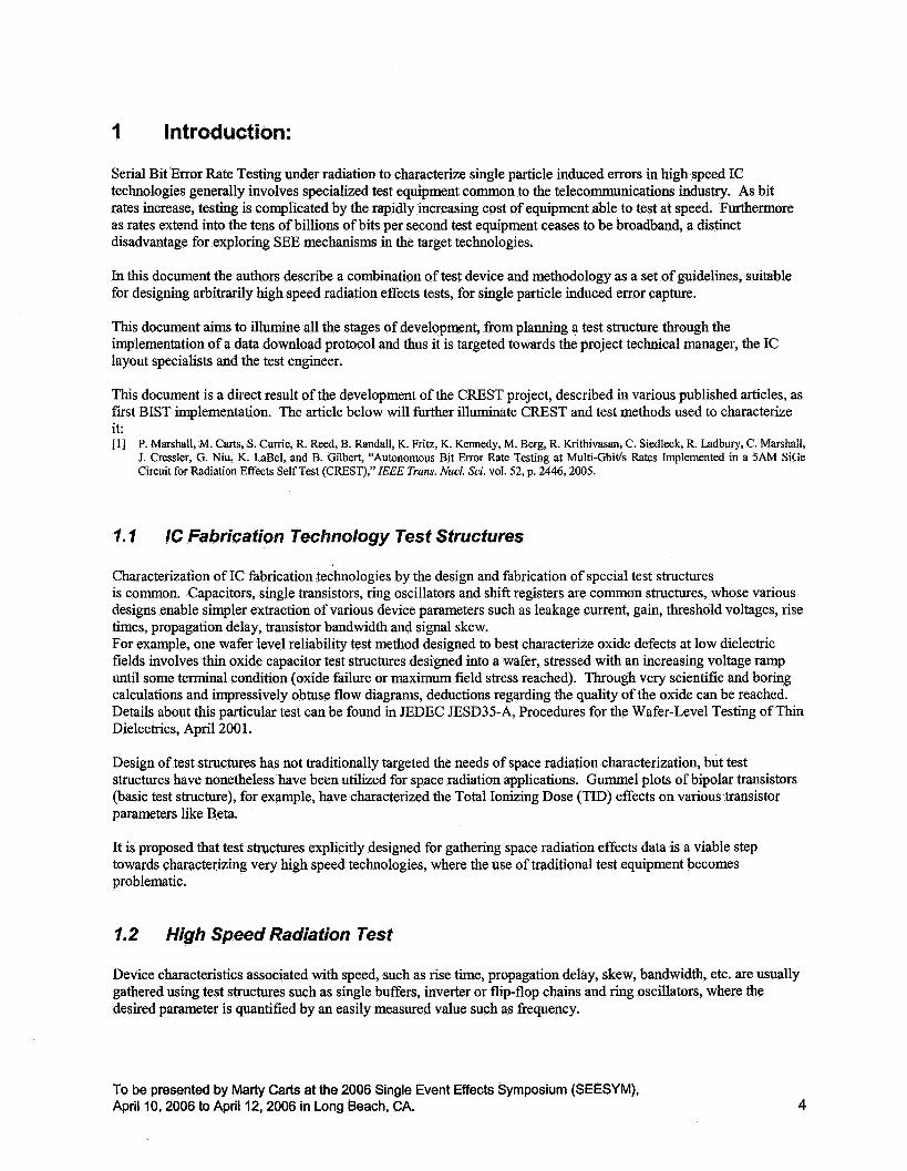
7.7 IC Fabrication Technology Test Structures
Characterization of IC fabrication technologies by the design and fabrication of special test structures is common. Capacitors, single transistors, ring oscillators and shift registers are common structures, whose various designs enable simpler extraction of various device parameters such as leakage current, gain, threshold voltages, rise times, propagation delay, transistor bandwidth and signal skew. For example, one wafer level reliability test method designed to best characterize oxide defects at low dielectric fields involves thin oxide capacitor test structures designed into a wafer, stressed with an increasing voltage ramp until some terminal condition (oxide failure or maximum field stress reached). Through very scientific and boring calculations and impressively obtuse flow diagrams, deductions regarding the quality of the oxide can be reached. Details about this particular test can be found in JEDEC JESD35-A, Procedures for the Wafer-Level Testing of Thin Dielectrics, April 200 1.
Design of test structures has not traditionally targeted the needs of space radiation characterization, but test structures have nonetheless have been utilized for space radiation applications. Gummel plots of bipolar transistors (basic test structure), for example, have characterized the Total Ionizing Dose (TID) effects on various transistor parameters like Beta.
It is proposed that test structures explicitly designed for gathering space radiation effects data is a viable step towards characterizing very high speed technologies, where the use of traditional test equipment becomes problematic.
1.2 High Speed Radiation Test
Device characteristics associated with speed, such as rise time, propagation delay, skew, bandwidth, etc. are usually gathered using test structures such as single buffers, inverter or flip-flop chains and ring oscillators, where the desired parameter is quantified by an easily measured value such as frequency.
To be presented by Maw Carts at the 2006 Single Event Effects Symposium (SEESYM), April 10,2006 to April 12,2006 in Long Beach, CA. 4

Single event radiation effects include flips of stored information (e.g. within flip flops) and, as fiequency of operation increases, transient pulses which are clocked erroneously into storage. Long chains of combinatorial circuitry (i.e. buffer or inverter chains) which lack storage make collection of single event information less effective since transient pulses which might flip storage elements or be clocked into storage elements might very well also diminish as propagated through many stages of inverter or buffer. The pulses which thus do not propagate are not visible and are not gathered as data.
However, such combinatorial structures do comprise significant portions of real-world circuitry in the form of clock distribution trees, and so they are important to include in a test structure.
Circuitry with storage capacity is called “sequential circuitry” because its ability to store information allows it to sequence fiom a previous “state” to a new state based on its previous value. This includes latches, flip flops, and the various forms of memory. Sequential circuitry allows both both upset of stored information and clocking in of transient information, and all single event errors thus gathered will be available for capture at the output of the circuit. Furthermore sequential circuitry is likely to make up much of a real-world circuit, e.g. in the form of registers and latches.
A shift register comprised of a serial chain of flip-flops seems to be the favored test structure for high speed radiation testing. It includes both a significant fraction of sequential circuitry and an accompanying fraction of combinatorial circuitry in the requisite clock tree. The actual proportions of the two types will depend on the actual technology-Technology capable of larger fanout at maximum speed will require a smaller fiaction of combinatorial circuitry for clock distribution.
The serial shift register is also a transmission channel as described in the next section, and thus is an appropriate structure to test with commercially available test equipment. Radiation testing is an area which has traditionally been secondary to the basic device parameter testing when test structures are designed. Radiation effects testing usually is done on mature integrated circuits and occasionally on the test structures used for basic process characterization. Shift registers do occur as basic test structures but they can lack optimization to run at high speeds, relegating their operation to well below the technology’s potential bandwidth and thus limiting their value for assessing high speed radiation susceptibility. Speed optimization of shift registers includes providing adequate fan-out of clock drive to each stage, and minimizing timing skew of the clock signal as received by each stage wrt the previous and next stages.
7.3 High Speed Test Equipment
The telecommunications industry supports test equipment capable of characterizing the integrity of information flowing through a serial transmission channel. Whether the channel is cabling from one device to another or open air modulated carrier transmission, whether the channel includes an explicit clock signal, and whether or not the information is modified by encoding for various reasons, the basic characteristic of said transmission channel is that the information is replicated at the output exactly as it was at the input and that in one form or another synchronization information is conveyed along with the data.
Bit Error Rate Test (BERT) equipment exists in many forms, optimized for different applications. Functionality of BERT equipment can be separated into test signal generation and test signal analysis; historically BERT functionality has been complex enough that the generator and the analyzer have often been separate pieces of equipment. It may be a trend in test equipment to incorporate these functions into one unit as the proportion of the total equipment cost shifts fiom the high frequency components to the data processing components. Some BERT equipment’s features are highly tuned to individual applications and include test functionality for higher layers of the OS1 model. For example, equipment which tests all layers of telephone line, cell phone, broadcast radio or fiber optic transmission channels, exist and are built into one chassis. The target of this equipment is fiequently field service or the manufacturing process, or both.
Other BERT equipment is designed to be maximally flexible and fully featured, providing the capability of testing the lowest OS1 model layers, typically at higher cost. It is this more fundamental, laboratory-use, equipment which is most useful for the various single event radiation testing. A single particle event can cause one bit or many bits to be in error. A group of bit errors caused by one particle strike is called a burst. The exact bit pattern can convey
To be presented by Marty Carts at the 2006 Single Event Effects Symposium (SEESYM), April 10,2006 to April 12,2006 in Long Beach, CA. 5

much information regarding the location of the strike and the mechanism of the error event. For example in an alternating HI-LO pattern if a string of seven bits end up being LO, that is, three HI bits erroneously changed to LO, it can be surmised that the event saturated or held some node in a LO state and lasted between five and seven bits duration. Thus the ability to read the actual bit values within and around an error event is important in single event radiation testing.
At risk of oversimplification, currently available fully featured commercial BERT equipment can be grouped into two categories. Up to bit rates of -12 GBPS BERT equipment is generally broadband, operating from whatever maximum datarate down to some low frequency, perhaps 50 MBPS, providing a total bandwidth of over two decades. Above this rate equipment becomes relatively narrowband, operating a datarate range of approximately one octave. Testing at the highest rates then tends to preclude wide fiequency range testing, which is important especially as error-mitigation schemes are employed.
2 Characteristics of a Test Structure
The serial shift register makes an excellent test structure due to its composition and its simple transmission channel form, but might not be the most appropriate for all applications. For example, the serializer/deserializer (SERDES) is an increasingly important component in systems as physical channels between systems are constricted to serial format for either economy and/or due to physical constraints, while operating speed within a system is reduced for power consumption, EM1 and synchronization reasons. A BIST design might be for a particular test structure, such as the serial shift register favored by the authors and illustrated in this document, but it should be recognized that the fundamental characteristics of a BIST circuit for space radiation study in high speed technologies ought to have the following characteristics:
2. I Contained High Speed Operation High speed operation restricted to within the test structure to the maximum degree practicable. Clock drive is excepted in the example illustrated in this document but conceivably the clock source could be integrated into the test structure. Minimizing the external routing and processing of high speed signals ought to reduces the complexity of the test as a whole.
2.2 Predictable Data The test data must be predictable in a way that allows for the test structure hardware to check the data for validity. Perhaps most simply, a pattern which repeats itself in time allows for an older bit to be compared with a new bit timed exactly an integral number of pattern repetitions later. In the illustrated system the pattern length is 127 bits long and each bit is compared with a bit one pattern apart in time. Alternatively an encoding scheme such as 8B/10B might have a disparity accumulator to detect errors. It is not imperative that perfect error detection occur. That is, some types of error pattern might escape an error detector composed of a disparity accumulator. If the error detection is not perfect then the decision must be made that whether the actual occurrence rate of error events will be extractable from the data gathered, and whether the residual uncertainty is acceptable.
2.3 Data Storage and Accessibility The data associated with an error event must be available for reading by external devices. In the illustrated example the entire test structure clock is halted upon error detection and the error data was held in the test structure itself (although the time delay from error detection to clock halt requires a post-shift register register to prevent some of the error data from being lost). Alternatively a register which loads fiom the test structure upon error detection could be implemented, taking a snapshot of the pertinent data in the test structure, allowing for continuous high speed clock operation. Consideration must be given to the effects on data validity of methods such as clock halt. In the illustrated example the error event rate was adjustable such that a large fraction of time was spent running at high speed; the effects of the halted high speed clock on the data were determined to be minimal.
Furthermore, the test structure must have whatever outputs and control inputs are required for outloading the data. The outloading must be sympathetic to the need to maintain data validity, for example by allowing rapid data outload and test continuation. It follows that the external equipment must be likewise suitable also.
To be presented by Marty Carts at the 2006 Single Event Effects Symposium (SEESYM), April 10,2006 to April 12,2006 in Long Beach, CA. 6

3 The Serial Shift Register Test Structure An implementation of the serial shift register, CREST (Circuit for Radiation Effects Self-Test), provided validation for the BIST. This section describes the scheme and the various elements of the whole test structure starting with the serial shift register. Refer to figures 1 and 2 at the end of this section for illustration of the test structure descriptions.
A string of single-bit element storage cells are connected sequentially and data is passed into the first cell, and from one to the next and finally out the last. Generally master-slave flip-flops are used to simplify the timing of the data flow. Master-slave flip flops (MS FFs, or simply FFs) have two portions, one of which latches in the next value while the next outputs the previous value. After the next value is finished being latched it is made available at the FF’s output.
There are issues with ensuring that the shift register can operate at maximum frequency. For one, every FF is fed the same clock signal. Long shift registers require large clock fanout. Different technologies have different fanout considerations. CMOS circuitry has very large DC fanout, but its maximum operating frequency is limited by the ability of the clock drive to charge the total gate capacitance connected to it. Current-steered logic using bipolar transistors have significant input DC current draw and thus have limited fanout regardless of frequency of operation. Attention to fanout loading is necessary for maximum frequency operation.
Final clock fanout for shifi registers several hundred cells long using buffers of maximum fanout of n requires that one driver feed multiple drivers, each of which feeds multiple drivers, etc. until a ‘tree’ of clock drivers with a large enough base, or total number of clock outputs, is achieved. Each driver has a range of possible propagation delays. Some sequential cells will be fed from the same driver but some will have driver paths entirely discrete up to the first driver in the tree. This allows for the accumulation of large clock propagation delay differences, or clock skew, and will limit the maximum frequency of operation. Attention to designing the clock tree to minimize the clock skew is important in shift register design.
3.7 Data Generator
It is not necessary that the data source be integral to the test circuit. However, the benefit of having the test circuit is largely that its high frequency operation is independent of any external equipment so it is presumed that the datasource is on-die. In general, the clock may be on chip as well tho advantages of external clock sourcing may outweigh the benefit of system simplicity, as in the illustrated example: Adjustable and precise frequency, low jitter, and little concern paid to the clock source during test structure design.
In the case of a serial shift register with the error detection used in this example, whatever the data source and whatever the data pattern length, the length of the shift register must be the same as the pattern length (or an integer multiple). Issues such as the die area used, the die powerheat budget, the single event sensitivity (and thus the fluence, total dose and device degradation needed to gather sufficient data) will factor into the decision to use patterns of given length. Possibly other, more application specific issues will be of concern also, such as the maximum length of strings of LO or HI bits. The maxim time duration of unchanging bit value will affect voltage droop in AC coupled systems.
3.1.1 PRBS Patterns
Serial bit error rate testing can give dramatically different results depending on the pattern of 1s and Os. For one example, if for a period of time all the bits are the same level then there are no edges, and so clock recovery circuits might not function well. Additionally, if there is AC coupling of the serial bit stream anywhere in the transmission channel the signal will droop according to the RC time constant of the path at the coupling. Droop continues to lower the noise margin as more bits remain unchanged. Because of this it is desirable that real-world signals have very frequent edges, and also that test signals have longer periods between edges to better stress the system.
To be presented by Marty Carts at the 2006 Single Event Effects Symposium (SEESYM), April 10,2006 to April 12,2006 in Long Beach, CA. 7

A test pattern which has the widest possible range of bit patterns is frequently used instead of or in addition to other obvious patterns (such as idle hmes in a system which has such higher IS0 layers ‘specified). The Pseudo- Random Bit Sequence2 (PRBS) or Pseudo-Random Number (PRN or PN) fills this need. It is a standard test pattern. The PN7 pattern, is 27-1 = 127 bits long, is commonly used and is recommended for use in this circuit. Every possible sequence of 7 bits (except 7 zeros) is found within this pattern.
Pattern polarity inversion and reversal occasionally cause difficulties in coordinating between dissimilar test signal source and analysis so it is recommended that a norm be established The positive polarity PN7 pattern will have 7 HI bits in a row, and only 6 LO bits in a row; the 7 HI bits immediately precede the 6 LO bits. Differences from the standard need to be noted.
3.1 -2 PN7 Data Generator The circuit shown in the Data Source block of Figure 2 generates a PN7 pattern. The state of each all seven flip flops describes the state of the PN7 generator. It is left as an exercise for the reader to show that, starting from any state except all zeros, the seven flip flops proceed thru 127 different states and then repeat, and that every 7 bit pattern (except all zeros) is produced by the source.
3.1.3 PRBS Reset
The seven FFs of the PN7 have 27 different states possible. Any of 127 of these will progress to another state upon the next clock cycle, and eventually all states except one will occur, and then the pattern will repeat. The one excepted state, called the zero state, will not progress at all but will be followed by the same, zero, state. A zero- state detection circuit (a seven input OR) is sometimes used to escape from the zero state but is not desirable in this kind of radiation testing, as it is desired that such an SEU will be caught by the error detection circuitry. Having an autonomous zero-state recovery circuit would obscure the results. Instead, the circuit is manually reset-able by an external signal, PRN-CLR.
3.2 Defecting €rrors The key characteristic of the PN7 pattern is that it repeats every 127 bits. Thus, any bit ought to be identical to the bit that precedes or follows it by 127 bits. Actually making this comparison is how the bitstream is monitored for errors. The shift register and the data pattern length must be the same in order for this scheme to work. Tho other lengths would work, and tho in fact in this test structure any repeating pattern 127 bits long would work, the PN7 has shown itself to be desirable and suitable.
If the die area or the power consumption of the technology made such a length problematic a PN6 or 63 bit long pattern, for example, could be used, trading sensitive area for total power consumption and area. PN7 was used in the CREST project and is recommended as good and is assumed in the rest of this document.
The 127-bit long shift register entry and exit points are labeled “DO” and “D127” respectively, and are the bits compared.
3.2.1 Error Detector XOR
An Exclusive OR (XOR) logic function outputs a LO when the two inputs are the same, and it outputs a HI when the two inputs are not the same. Alternatively, the XOR can be seen as a difference detector (this is precisely the use of the XOR in some PLL circuits), outputting HI when the inputs are different. To the extent that there are no errors in the datastream flowing through the shift register, the output of the XOR will remain, essentially, LO.
One explanation of the IS0 refernce model is to be found at: http:llwww.erg.abdn.ac.ukfuserslgorrylcourselin~o- 1
pageslosi. html
To be presented by Marty Carts at the 2006 Single Event Effects Symposium (SEESYM), April I O , 2006 to April 12,2006 in Long Beach, CA. 8

Except in Marty’sPerfectWorldW, the XOR output will have transient spikes while the two input’s values are changing because the two data inputs at bit transitions can never actually be identical. The mid-bit value is unaffected tho, so the XOR output is sampled mid-bit. This sampled value is the “Error” signal. If it is HI it is a clear indication of of a miscompare between the DO and D127 bits.
Following circuitry will act upon a HI Error signal and halt the operation of the entire shift register.
3.2.2 Error Latch A bit miscompare, resulting in a HI XOR output is both sampled to reject bit-edge transients as described above and is latched and held, by a FF. This latched error signal, Err-Flag, is synchronous with the clock.
3.2.3 Retaining Error Data-The FIFO When a bit error occurs and Err-Flag goes HI, the clock signal for the entire chip is halted after as short a period of time as is possible, and the outside world is notified by the latched value. At higher frequencies there will be a significant time delay between detecting the error and the cessation of the clock distribution, in terms of bit periods, in the CREST device, this can be on the order of 4 or 5 bits. In order to not loose data when halting the chip clock a pipeline, a FIFO, additional shift register FFs, is added to the output of the shift register so that all data, including some pre-error data, will be retained. In the case of the CREST chip 8 additional bits of shift register were added. The input to this addition is the aforementioned D 127 and similarly the output is called “D 135”.
Also, the output of the error detecting XOR is fed into an identical FIFO. Because it is associated with the shift register output bit, D127, the XOR output bit is labeled “E127”, even tho there are no EO thru E126 bits. Similarly the output of the error FIFO is called “E135”.
The modeling of the time delay around the loop from the XOR to the end of the clock tree is not necessarily an accurate measure of the actual delay. It is suggested that more than the calculated minimum depth of FIFO be included in the design.
3.3 Stopping and Controlling the Clock
3.3.1 Clock Slivers Especially at maximum data rate, maintaining above the minimum width of the clock signal pulse is critical for error-free operation. The Err-Flag signal will stop the clock upon detection of an error. The En-Flag signal is synchronous, but if it were to feed the disable control of the main clock control buffer, this synchronicity would not be enough to ensure that under all conditions only full clock pulses would pass to the rest of the test structure. The total propagation delay from the Error signal through the clock control circuitry, through the entire clock tree, and then thru the XOR back to the Error signal can be multiple clock cycles at high frequency. At some frequencies this delay will be an integral number of clock cycles, but it would not be broadband operation.
Should a clock pulse be cut off prematurely, it could cause, for example, some FFs to shift while other do not. Such shortening of clock pulses is called slivering, and must be avoided. The main clock control buffer which feeds the clock signal to all clock circuits on the test structure, and which disables the clock, is in a very small loop, so that the disable signal to the buffer occurs immediately after the falling edge of the clock and before it is possible for the next rising edge of the clock to occur.
3.3.2 Clock Control Buffer The clock signal to be distributed to the entire test structure passes through a buffer with a disable control. This clock control buffer is part of the anti-sliver loop. When an error occurs the clock is disabled while in the LO state, so that after the end of the last clock pulse propagates through the rest of the test structure all is static from the clock control buffer onwards. At that point external circuitry can, at its leisure, switch the clock signal applied to the input of the Clock Control Buffer to a low frequency clock. As described below additional external control can then reenable the clock, in such a way that slivers are again prevented on the leading edge of the next clock pulse, in order to
To be presented by Marty Carts at the 2006 Single Event Effects Symposium (SEESYM), April 10,2006 to April 12,2006 in Long Beach, CA. 9

3.3.3 Error Override Once error capture has occurred and the clock is stopped the clock source is switched from the high speed clock to a low speed clock in order to read the data and error bits from the output of the FIFO. Determining which clock to use is the hc t ion of an external input, CLK-Sel.
CLK-Sel is set to select the low frequency clock, CLK-LO, which in the CREST project has been a control signal instead of a continuously running clock. It is set to the LO state.
At that point the Error Latch can be overridden without loss of data-The clock signal is held in the LO state so data will not shift along the shift register and the FIFOs.
An AND gate allows for the override of the normally LO, but HI during error condition, Error signal input to the anti-sliver latch in the clock control circuitry. The inverted input of this AND gate is called CLK-Force. Once it is asserted (HI) then clock pulses at the CLK-LO input to the test structure will properly clock the test structure.
3.4 Data Readout and Rearming
3.4.1 Error Data Readout
After an error occurs, then after the abovementioned preparatory steps have occurred, the data can be read out. The two test structure outputs, D135 and E135, assert the values of the shift register and the calculated Error signal from before the error occurred. After these values are red the CLK-LO signal is pulsed, shifting the data along the shift register and FIFOs to present the next D and E values to the test structure outputs D 135 and El 35. Repeating this for a total of 136 times will read out all of the data stored within the shift register and will have clocked the PN7 to feed new data into the DO input to the shift register.
3.4.2 Clearing Error Latch The latch on the output of the XOR is armed like a mousetrap. When tripped at the detection of an error by the XOR, it remains tripped throughout the data readout process. After all desired data has been read out, it can be rearmed.
Presumably the 136 clock pulses has clocked error-free data into and through the shift register. So the XOR is presumed to be LO, indicating no miscompare. An AND gate at the the Error Latch output, within the Error Latch feedback loop, normally has a HI applied to its second input. In error-free operation the first AND input is LO, and when an error is latched it goes HI. Forcing the second AND input, called CLEARbar (active LO) LO forces the AND gate output LO and clears the error condition, if the XOR output is LO (indicating no miscompare) and at least one test structure clock pulse occurs. Then, the Clearbar signal can be deasserted (toggled back to HI) and the Error Latch mousetrap is rearmed.
3.4.3 Variations on the ClearinglArming Sequence Variations of the error clearinghearming process are possible, and are likely desirable. It is expected that the test structure would be operated at relatively high speeds and that the error detectioddata outloadrearming process would occur during irradiation. The fraction of time that the circuitry is responding to errors and not running at speed, should be very low. If an error rate of, say, 10 per second is set, and it takes 10 ms to detectloutloadrearm once, then approximately 10% of the error events will have another error occur before the process is completed. While this does not invalidate those data points it both complicates the error analysis and it represents error data that is taken at very low speed, affecting the datarate factor of the SEU cross section.
Maximizing the speed of the external equipment controlling and outloading the data is one way to minimize this effect. In the CREST project a CLK-LO rate of approximately 1 MHz was used and the entire outloadrearm process (not counting the detection time) took approximately % ms. The CREST equipment was programmed to
To be presented by Marty Carts at the 2006 Single Event Effects Symposium (SEESYM), April I O , 2006 to April 12,2006 in Long Beach, CA. 10
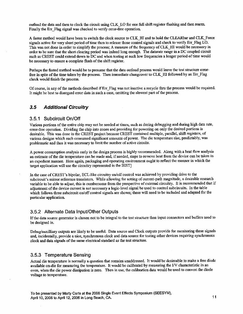
outload the data and then to clock the circuit using CLK-LO for one full shift register flushing and then rearm. Finally the Err-Flag signal was checked to verify error-free operation.
A faster method would have been to switch the clock source to CLK-HI and to hold the CLEARbar and CLK-Force signals active for very short period of time then to release those control signals and check to verify Err-Flag LO. This was not done in order to simplify the process; A measure of the frequency of CLK-HI would be necessary in order to be sure that the short clearing period was indeed long enough. The datarate range in a DC coupled circuit such as CREST could extend down to DC and when testing at such low frequencies a longer period of time would be necessary to ensure a complete flush of the shift register.
Perhaps the fasted method would be to presume that the data outload process would leave the test structure error- free in spite of the time taken by the process. Then immediate changeover to CLK-HI followed by an Err-Flag check would finish the process.
Of course, in any of the methods described if Err-Flag was not inactive a recycle thru the process would be required. It might be best to disregard error data in such a case, omitting the slowest part of the process.
3.5 Additional Circuitry
3.5.1 Subcircuit On/Off Various portions of the entire chip may not be needed at times, such as during debugging and during high data rate, error-free operation. Dividing the chip into zones and providing for powering on only the desired portions is desirable. This was done in the CREST project because CREST contained multiple, parallel, shift registers, of various designs which each consumed significant amounts of power. The die temperature rise, predictably, was problematic and thus it was necessary to limit the number of active circuits.
A power consumption analysis early in the design process is highly recommended. Along with a heat flow analysis an estimate of the die temperature can be made and, if needed, steps to remove heat from the device can be taken in an expedient manner. Here again, packaging and operating environment ought to reflect the manner in which the target application will use the circuitry represented in the BIST]
In the case of CREST’S bipolar, ECL-like circuitry ordoff control was achieved by providing drive to the subcircuit’s mirror reference transistors. While allowing for setting of current-path magnitude, a desirable research variable to be able to adjust, this is cumbersome from the perspective of external circuitry. It is recommended that if adjustment of the device current is not necessary a logic-level signal be used to control subcircuits. In the table which follows three subcircuit odoff control signals are shown; these will need to be included and adapted for the particular application.
3.5.2 Alternate Data InpuVOther Outputs If the data source generator is chosen not to be integral to the test structure then input connectors and buffers need to be designed in.
Debuglauxilliary outputs are likely to be useful. Data source and Clock outputs provide for monitoring these signals and, incidentally, provide a nice, synchronous clock and data source for testing other devices requiring synchronous clock and data signals of the same electrical standard as the test structure.
3.5.3 Temperature Sensing Actual die temperature is normally a question that remains unaddressed. It would be desireable to make a free diode available on-die for measuring the temperature. It would be calibrated by measuring the W characteristic in an oven, when the die power dissipation is zero. Then in use, the calibration data would be used to convert the diode voltage to temperature.
To be presented by Marty Carts at the 2006 Single Event Effects Symposium (SEESYM), April I O , 2006 to April 12,2006 in Long Beach, CA. 11

3.6 External Equipment Connections
See Table 1 for a list of all the connections associated with the description of the general BIST test structure. Inputloutput level standards need to be chosen for compatibility with both hardware and for appropriate signal handling. For example, modern FPGA circuits are typically either indifferent to or are intolerant of 5V signal levels. High speed technologies such as the 5Hp process used in the CREST project are also intolerant of voltages much higher than +1.5 Volts as applied in the CREST project. Thus it made sense to choose signal standards to accommodate these limitations, such as LVCMOS 1.2 and LVDS.
A high speed signal standard called CML, which is different than the CML referred to in some commercial products, is a differential standard with nominally 300 mVpp swing fi-om OV (HI) to -300 mV (LO). This is what is referred to as CML in all places in this document.
The suggested I/O levels are chosen to be roughly the same as on CREST, except that the LVDS signals will be single-ended CMOS instead. LVCMOS12, a 1.2V logic, is currently the lowest level commonly available in the FPGAs which might be used to control this device.
The connector and cable types of the table are suggestions. The power connections are simple; Voltage sensing is provided for, assuming significant current-draw.
The CML signals are necessarily high quality coaxial cable if datarates above the several GBPS range are to be achieved. SMA or like connectors will be required at these datarates too; BNC connectors will not be adequate.
It is suggested that there are too many control signals for convenient use of coaxial cables, and that a high speed ribbon cable be used. Controlled impedance ribbon cable is available allowing signal-ground-signal-ground conductor allocation, as are appropriate mating connectors.
To be presented by Matty Carts at the 2006 Single Event Effects Symposium (SEESYM), April I O , 2006 to April 12,2006 in Long Beach, CA. 12

3.7 Physical Mounting of the Test Structure The CREST project used a high frequency dielectric printed circuit board (PCB), mounted to a strength layer (Aluminum), to mount the test structure die. Wire bonds from the die to the substrate completed the interconnections. Power terminal block, ribbon cable connectors, and SMA connectors were mounted either to the PCB or to the Aluminum with connection to the PCB. In this manner very wide particle beam angle range was established.
As mentioned earlier attention to heat dissipation issues early in the process is highly recommended. Due to the technology (bipolar) and the large number of shift registers and additional circuitry (not described here) CREST had a heat issue. Conduction thru the PCB was inadequate, even with substantial cooling applied to the Aluminum layer. It was found that air flow provided very good cooling. Future designs ought use forced air cooling from the back side if possible, instead of the incident beam side.
The physical design also included standoffs for mounting of a protective cover; with exposed wire bonds attention needs to be given to safe storage and handling.
To be presented by Marty Carts at the 2006 Single Event Effects Symposium (SEESYM), April I O , 2006 to April 12,2006 in Long Beach, CA. 13

(from Error Latch circuit,
previous sheet)
CLK-Force
Err-Flag (to external equipment)
Error
CLK-Out
t K CLK-HI
CLK-LO
CLK-Sel
Figure 1. CREST Clock Control Circuitry
PR
CLK
D( ................................ i
i Datasource i (Internal Z7-l PRN i
shown) ..................................
)ut
CLK
...........................
i The Test Structure i (127 bit long shift
register) .................................
CLK
..................................... i
Data-saving FIFO i .......................................
CREST Data Circuitry (clock control circuitry shown elsewhere)
i The Error Detection and Latch Circuitry i ..................................................................
Figure 2. Data Path and Error Detection
To be presented by Marty Carts at the 2006 Single Event Effects Symposium (SEESYM), April 10,2006 to April 12,2006 in Long Beach, CA. 14

4 External Equipment External equipment is, by design, relatively simple. It consists of a clock source and a controller to manipulate the test structure and outload the data from the structure.
4.7 Clock Source Typical clock sources at high frequencies are CW, sine wave, and are AC coupled. It is incumbent upon the testers to provide for splitting this into a differential signal and applying a DC bias to it, as necessary to match the signal standard for the CLOCK input. It might be a reasonable simplification to design a single-ended, zero offset, clock signal, significantly simplifying the clock sourcing task.
4.2 Controller
If speed is not a concern then simple computer I/O accessories can be used to control the test structure and to outload data. However, the speed will likely be several orders of magnitude slower than what is achievable with a dedicated FPGA controller. Specialized pattern generators have not been considered but might significantly improve upon the speed of the simple computer I/O.
In either case a host computer is at the end of the chain of equipment, either as host of the simple 110 accessories or by interface to the FPGA controller.
It is recommended that an FPGA controller is the obvious, fastest solution. The functionality of the FPGA controller as implemented in the CREST project and as recommended here, is multiple:
4.2.1 Computer control The host computer interfaces with the FPGA and according to either user command or by programmatic dictate it sends commands to the FPGA to, for example, initially arm the test structure and wait to process errors.
The CREST project computer control included several capabilities. Command of the FPGA controller was achieved by a control register of 16 bytes total size. Mode was selectable via control register.
Manual Mode allowed for the manipulation of all the control signals of the test structure. This proved invaluable in the debugldevelopment phase of the project.
Quiescent mode allowed for manipulation of the subcircuit odoff controls.
Various test modes allowed for, example, the FPGA controller to host computer data path, described further below.
Run Mode set the FPGA controller to initialize the test structure and to wait to outload error data. This mode was terminal. It was not deemed necessary to gracefully return from this mode, so exiting this test mode required the resetting of the FPGA controller.
4.2.2 Test Structure Interface According to the dictates of the host computer the FPGA controller controlled the various portions of the test structure. When set to the Run Mode the FPGA was designed to operate without delay to data outloading demands of the test structure.
To be presented by Marty Carts at the 2006 Single Event Effects Symposium (SEESYM), April 10,2006 to April 12,2006 in Long Beach, CA. 15
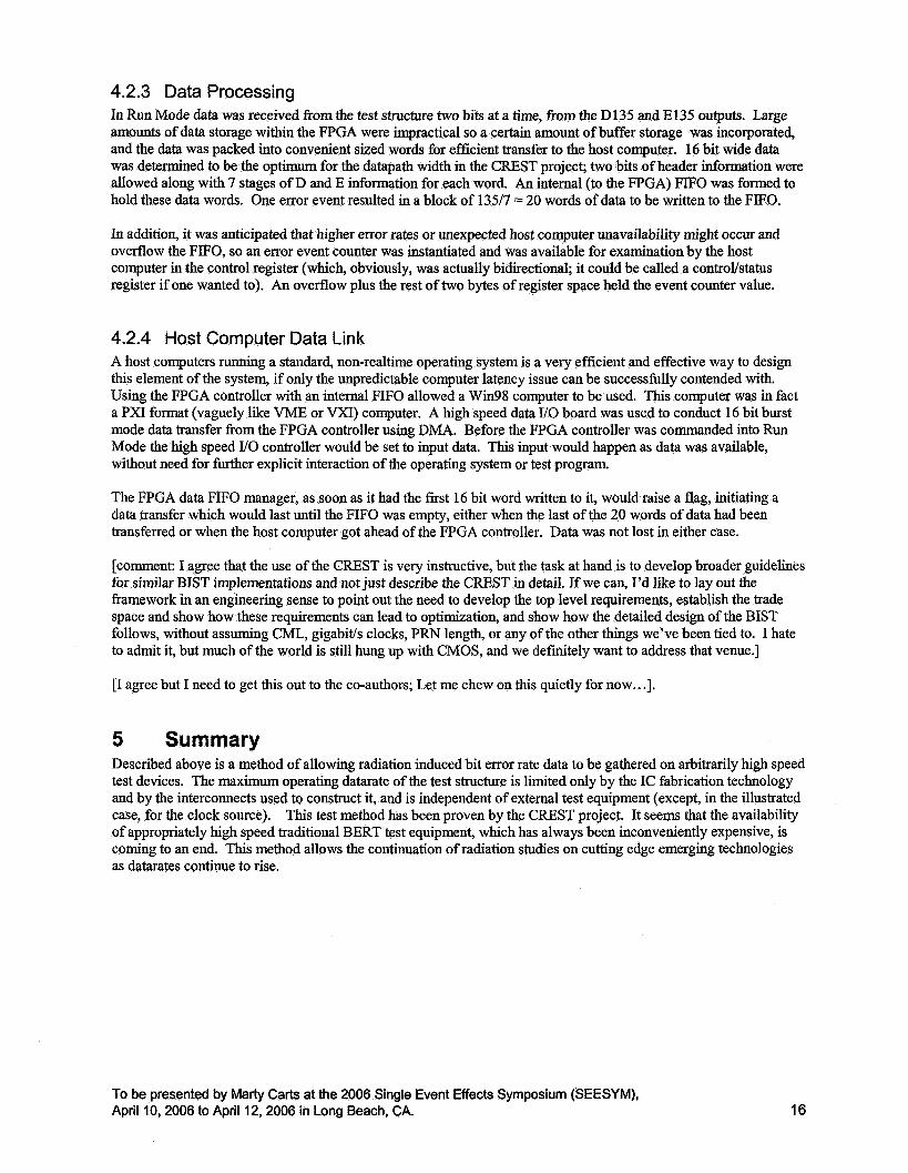
4.2.3 Data Processing In Run Mode data was received from the test structure two bits at a time, from the D135 and E135 outputs. Large amounts of data storage within the FPGA were impractical so a certain amount of buffer storage was incorporated, and the data was packed into convenient sized words for efficient transfer to the host computer. 16 bit wide data was determined to be the optimum for the datapath width in the CREST project; two bits of header information were allowed along with 7 stages of D and E information for each word. An internal (to the FPGA) FIFO was formed to hold these data words. One error event resulted in a block of 13517 = 20 words of data to be written to the FIFO.
In addition, it was anticipated that higher error rates or unexpected host computer unavailability might occur and overflow the FIFO, so an error event counter was instantiated and was available for examination by the host computer in the control register (which, obviously, was actually bidirectional; it could be called a control/status register if one wanted to). An overflow plus the rest of two bytes of register space held the event counter value.
4.2.4 Host Computer Data Link A host computers running a standard, non-realtime operating system is a very efficient and effective way to design this element of the system, if only the unpredictable computer latency issue can be successfully contended with. Using the FPGA controller with an internal FIFO allowed a Win98 computer to be used. This computer was in fact a PXI format (vaguely like VME or VXI) computer. A high speed data I/O board was used to conduct 16 bit burst mode data transfer from the FPGA controller using DMA. Before the FPGA controller was commanded into Run Mode the high speed I/O controller would be set to input data. This input would happen as data was available, without need for fhrther explicit interaction of the operating system or test program
The FPGA data FIFO manager, as soon as it had the first 16 bit word written to it, would raise a flag, initiating a data transfer which would last until the FIFO was empty, either when the last of the 20 words of data had been transferred or when the host computer got ahead of the FPGA controller. Data was not lost in either case.
[comment: I agree that the use of the CREST is very instructive, but the task at hand is to develop broader guidelines for similar BIST implementations and not just describe the CREST in detail. If we can, I’d like to lay out the framework in an engineering sense to point out the need to develop the top level requirements, establish the trade space and show how these requirements can lead to optimization, and show how the detailed design of the BIST follows, without assuming CML, gigabids clocks, PRN length, or any of the other things we’ve been tied to. I hate to admit it, but much of the world is still hung up with CMOS, and we definitely want to address that venue.]
[I agree but I need to get this out to the co-authors; Let me chew on this quietly for now...],
5 Summary Described above is a method of allowing radiation induced bit error rate data to be gathered on arbitrarily high speed test devices. The maximum operating datarate of the test structure is limited only by the IC fabrication technology and by the interconnects used to construct it, and is independent of external test equipment (except, in the illustrated case, for the clock source). This test method has been proven by the CREST project. It seems that the availability of appropriately high speed traditional BERT test equipment, which has always been inconveniently expensive, is coming to an end. This method allows the continuation of radiation studies on cutting edge emerging technologies as datarates continue to rise.
To be presented by Marty Carts at the 2006 Single Event Effects Symposium (SEESYM), April 10,2006 to April 12,2006 in Long Beach, CA. 16