Embed Size (px)
Citation preview

Full Paper
Fluorine Plasma Treatments of Poly(propylene)Films, 2 – Modeling Reaction Mechanisms andScalinga
Yang Yang, Mark Strobel, Seth Kirk, Mark J. Kushner*
M. J. KushnerDepartment of Electrical Engineering and Computer Science,University of Michigan, 1301 Beal Avenue, Ann Arbor, Michigan48109, USAE-mail: [email protected]. YangDepartment of Electrical and Computer Engineering, Iowa StateUniversity, Ames, Iowa 50011, USAM. Strobel, S. KirkCorporate Research Process Laboratory, 3M Company, 3M Center,St. Paul, Minnesota 55144, USAaPart 1: cf. ref.[27]
The surface properties of commodity hydrocarbon polymers such as poly(propylene) (PP) canbe modified by functionalization with plasma-generated radicals and ions. For example,affixing fluorine to a hydrocarbon surface lowers surface energy and increases hydrophobicity.One such process is treatment of PP films in low-pressure, capacitively coupled plasmas (CCPs)sustained in F2-containing gas mixtures. F atoms produced in the plasma abstract H atomsfrom the hydrocarbon and passivate the resulting alkyl sites producing C�Fn sites. Energeticion and photon fluxes sputter and initiate crosslinking. In this paper, the plasma fluorinationof PP in a CCP sustained in Ar/F2 is discussed with results from a two-dimensional plasmahydrodynamics model. The surface reactionmechanism includes a hierarchy of H abstractionand F/F2 passivation reactions, as well as cross-linking, and ion and photon-activated processes.Predictions for surface composition were com-pared to experiments. We found that the lack oftotal fluorination with long plasma exposure islikely caused by crosslinking, which creates C�Cbonds that might otherwise be passivated by Fatoms. Increasing steric hindrances as fluorina-tion proceeds also contribute to lower F/C ratios.
Plasma Process. Polym. 2010, 7, 123–150
� 2010 WILEY-VCH Verlag GmbH & Co. KGaA, Weinheim
Introduction
The fluorination of the surface layers of hydrocarbon
polymersmodifies thewettingproperties of thepolymerby
decreasing the surface energy and increasing hydrophobi-
city.[1–3] The fluorination process usually entails the
removal of hydrogen from the hydrocarbon polymer
backbone, forming an alkyl site, and the passivation of
the alkyl site with a fluorine atom.[4] As most hydrocarbon
polymers are heat sensitive, it is desirable for the
fluorination to take place at low temperatures. As such,
low-pressure, non-equilibrium plasmas are attractive
options for this surface treatment.
In low-pressure plasmas sustained in fluorine-contain-
ing feedstock gases, electron-impact reactions (mainly
by dissociative excitation or attachment) produce
DOI: 10.1002/ppap.200900114 123

Y. Yang, M. Strobel, S. Kirk, M. J. Kushner
124
fluorine-containing radicals at lowambientgas andsurface
temperatures. These radicals can both abstract hydrogen
from the polymer surface layers, producing alkyl sites, and
passivate those sites with fluorine atoms. Compared to
fluorination by exposure to elemental fluorine gas at
atmospheric pressure, low-pressure plasma fluorination
proceeds more rapidly and more controllably. Significant
fluorination of hydrocarbon polymers can occur in only a
few seconds in low-pressure plasmas.[5,6] This fluorination
typically occurs to a depthof atmost 10nmthereby leaving
the bulk properties largely unchanged.[7] An added feature
of plasma fluorination is that surface properties evolve
under the simultaneous influence of fluorine-containing
radicals, vacuum ultraviolet (VUV) radiation, and ion
bombardment.[8]
A measure of the fluorination of a hydrocarbon polymer
is the F/C atomic ratio of the surface layers, as determined
by X-ray photoelectron spectroscopy (XPS or ESCA). Corbin
et al. showed that in an inductively coupled Ar/F2¼ 95/5
discharge at 50W and 2 Torr, fluorination of polyethylene
(PE) to a F/C of 1.8 (themaximumF/C is 2.0) was achievable
in less than 1min.[9] Exposure to elemental fluorine gas
resulted in a F/C of 0.2 over 3min. Anand et al. performed
XPS to probe the surface layer and depth of fluorination
after treatmentofPE inan inductivelycoupledHe/F2¼ 95/5
plasma.[10] For a 3mTorr discharge at 50W, thefluorination
depth was about 4nm with there being competition
between ion-assisted etching and fluorination. The fluor-
ination depth increased with increase in pressure or flow
rates and the fluorinated surface was crosslinked. Hopkins
and Badyal treated a variety of polymers [including PE,
poly(propylene) (PP), polyisoprene, polystyrene, polycarbo-
nate] in 150mTorr, 50W inductively coupled CF4 plas-
mas.[11] Theyconcluded thathydrogenabstraction fromthe
polymer by fluorine to form HF is the initiating step to
plasma fluorination. This is thermodynamically favored
since C�H bond strengths are 3–4 eV as compared with
5.9 eV for H�F and 5.0 eV for C�F bonds. They found that,
compared with saturated polymers, unsaturated polymers
are more susceptible to plasma fluorination. A reaction
pathwaycomprisingfluorineadditionatC¼Cdoublebonds
was suggested.
Bond energies in hydrocarbonpolymers are 3–4 eVwhile
ions can gain tens to hundreds of eV in traversing the
plasma sheath at the polymer surface in a low-pressure
plasma. These ions are capable of breaking bonds, sputter-
ing and affecting surface composition through bond
scission, andsubsequent crosslinking. The sputteringyields
of ionsare functionsof incident ionenergy, polymer surface
bonding energy, andmass difference between the ions and
the atomormolecular fragments on thepolymer backbone.
Stelmashuk et al. and Biederman et al. performed radio-
frequency (rf) magnetron sputtering of PP in Ar plasmas
overpressures of 5–67mTorr andpowersof 25–100W.[12,13]
Plasma Process. Polym. 2010, 7, 123–150
� 2010 WILEY-VCH Verlag GmbH & Co. KGaA, Weinheim
Ion bombardment and subsequent heating of the PP caused
changes in the molecular structure of the target including
melting and crosslinking. They found that sputtering
preferentially lowered the proportion of CH3 groups in
the PP, transforming them into CH and CH2 groups, which
promoted crosslinking. They also found that the rates of
sputtering of PP and PE are less than one-third that for
polytetrafluoroethylene (PTFE). This is likely a result of the
more favorablemass ratio of the incidentAr ions to theC�F
bond in PTFE as compared with the C�H bond in PE.
Biederman modeled bombardment of PE by Ar ions using
moleculardynamics andproposed that the ions cause chain
scission, crosslinking, and carbonization of the target.[14]
The ejected species were dominated by atomic and
molecular hydrogen, but also included large chain frag-
ments containing up to 20CH2 units.
Vacuumultraviolet (VUV) radiation is typicallyproduced
in low-pressure plasmas. In particular, in Ar/F2 plasmas,
excited states of F, F2, and Ar produce radiation in the range
of95–157nm. Impurities (e.g.,H2O,O2, andCO2)alsoemit in
this region (115–360nm). The C�C or C�H bonds of
hydrocarbon polymers absorb radiation below 160nm
producing hemolytic bond scission and giving rise to either
polymer ablation or to the formation of functional groups
and reactive sites (e.g., double bonds and radicals).[15–20]
Corbin et al. investigated the enhancement of fluorination
of PE under VUV irradiation originating from a He/F2discharge.[21] The PE was immersed in a He/F2 mixture and
isolated from the plasma by a VUV-transmitting window.
They found that radiation below 180nm increased the rate
of fluorination. Dorofeev and Skurat performed photolysis
of PP in vacuumwith 147nm radiation from aXe lamp and
subsequent UV absorption spectroscopy on the irradiated
sample.[22–24] They found that PP photolysis at 147nm
primarily liberates H2 along with the formation of a C¼C
bondwithaquantumyield of about0.25. The scissionof the
C�C bond produces two radicals that undergo dispropor-
tionation forming a methyl group and a chain-end double
bond. They also observed scission of C�H and C�C bonds,
which splits the atomic hydrogen and methyl groups,
respectively, with a quantum yield about 0.025.
Ono et al. studied VUV photo-degradation of PTFE by
ultraviolet photoelectron spectroscopy (UPS) and quad-
ruple mass spectrometry.[25] They found that, unlike the
photolysis of PP and PE, C¼C bond generation is not amajor
process. They found CFn (n¼ 1–3) in the ejecta, indicating
that the polymer C�C backbone undergoes scission, a
process also observed by Skurat andNikiforov.[26] Ono et al.
estimated the quantumyield for atomic fluorine photolysis
at 147nm to be 0.0025.
In this paper, we present results from a computational
investigation of the gas-phase and surface kinetics
during the fluorination of PP in a low-pressure capacitively
coupled plasma (CCP) sustained in Ar/F2 while accounting
DOI: 10.1002/ppap.200900114

Fluorine Plasma Treatments of Poly(propylene) Films, 2 . . .
for both ionbombardment andVUV illumination.A surface
reaction mechanism for the fluorination of PP films was
developed, incorporated into a two-dimensional model for
gas and surface processes, and applied to a CCP reactor
patterned after an industrial prototype.[27] We found that
the degree of fluorination, as expressed by the F/C ratio,
affects the rate of additional fluorination due to a
deactivation effect and steric hindrance by adjacent F
atoms. For films electrically floating in the plasma (and not
in contact with an electrode) and with moderate exposure
times (<tens of seconds), ion bombardment is not
particularly important to the final F/C ratio. However,
given longer exposure time or placement of the film on an
electrode, ion sputtering produces significant changes in
surface composition. In general, photon-induced reactions
have little affect on film properties for moderate exposure
times (<tens of seconds) largely due to the lower
magnitudes of photon fluxes as compared with radical
and ion fluxes. We found that fluorination generally
increases monotonically with power, pressure, and F2concentration. Good agreement for fluorination rates and
surface compositions between model and experimental
results was achieved.
The integrated surface kinetics model and plasma-
equipment model used in this study and the gas-phase
reaction mechanism are described in the Description of
theModel and Gas Phase ReactionMechanism section. The
surface reaction mechanism is described in the Surface
Reaction Mechanism for PP Fluorination section. Plasma
properties for Ar/F2 mixtures in the CCP reactor are
discussed in the Plasma Properties of Ar/F2 Plasma section.
Results for plasma fluorination of PP are presented in the
Plasma Fluorination of PP. Concluding remarks are found in
the Conclusion section.
Figure 1. Schematic of the plasma fluorination reactor. Theplasma is produced in a capacitively coupled discharge betweentwo parallel electrodes. The PP web traverses the plasma regionat speeds of a few to tens of cm � s�1 with residence times of a fewto tens of seconds.
Description of the Model and Gas PhaseReaction Mechanism
The integrated plasma equipment-surface kinetics model
used in this investigation has been previously described
and so will be only briefly discussed here.[28] The Hybrid
Plasma Equipment Model (HPEM) is a 2-dimensional fluid
hydrodynamics simulation that, for CCP reactors, employs
fivemodules: theElectronEnergyTransportModule (EETM),
the Fluid Kinetics Module (FKM), the Plasma Chemistry
Monte CarloModule (PCMCM), the Surface KineticsModule
(SKM), and the Monte Carlo Radiation Transport Module
(MCRTM). Using a Monte Carlo simulation (MCS) for
secondary electrons emitted fromsurfaces, the EETMsolves
for electron-impact source functions and transport coeffi-
cients based on phase-resolved electrostatic fields from the
FKM. Results from the EETM are passed to the FKM, which
solves continuity, momentum, and energy equations for
Plasma Process. Polym. 2010, 7, 123–150
� 2010 WILEY-VCH Verlag GmbH & Co. KGaA, Weinheim
neutralsand ions, thecontinuityequation forelectrons, and
Poisson’s equation to determine time-resolved electrostatic
fields. In this particular implementation, the electron
energy equation for bulk electron energy transport is
solved within the FKM. Source functions and densities of
ions and excited states are then used in the PCMCM, SKM,
and MCRTM to update gas-phase rate coefficients and
surface coverages. The outputs from the FKM are then fed
back to the EETM, a sequence that constitutes an iteration.
Additional iterations are computed until a cycle-averaged
steady state is achieved. Acceleration techniques are
used to speed the cycle-averaged convergence of plasma
properties.
Following every iteration, the electric fields and source
functions for ions are recorded as a function of position and
phase in the rf cycle. With these values, the energy and
angular distributions of ions (IEADs) incident on the PP film
are obtained using the PCMCM described in detail in the
ref.[29] The IEADs are used to compute probabilities of
energy-dependentsurfaceprocessessuchassputtering.The
MCRTM, described in the ref.,[30] is also called after every
iteration to provide photon fluxes incident on the PP film.
The VUV radiation tracked in the model originates from
resonance transitions from F(3s) and Ar(4s) and from
F2 C1 Pu;H
1Pu
� �. An outcome of the MCRTM is trapping
factors for resonance radiation and these factors are used to
update the radiative lifetimes of the radiating states in the
reaction mechanism.
With the surface reaction mechanism described in the
Surface Reaction Mechanism for PP Fluorination section,
the SKM is called after each iteration to integrate the
coupled rate equations for the coverage of surface species
using site-balance techniques. Input to the SKM includes
fluxesof electrons, ions (andenergydistributions), neutrals,
andVUVradiation fromtheothermodulesof theHPEM.The
SKM is described in detail in the ref.[31]
Aschematicof theCCP reactorused in this study is shown
in Figure 1.[27] The parallel-plate reactor has electrodes
46 cm �46 cm separated by 2.54 cm. One electrode is
grounded and the opposite is powered at 10MHz through
a blocking capacitor. The feedstock gases are injected
www.plasma-polymers.org 125

Y. Yang, M. Strobel, S. Kirk, M. J. Kushner
126
through nozzles in both electrodes and pumped out
at the right side of the reactor. The reactor is integrated
into a web-processing line where a polymer film
enters from the left side of the reactor and translates to
the right where, in an actual device, the collector roll
might be located. Typical web speeds are up to several
to tens of cm � s�1 and the film spends from seconds to tens
of seconds in the discharge. The thickness of the PP film is
2.5� 10�3 cm, which is smaller than our mesh resolution.
In principle, this discrepancy should only affect the
electrical properties of the film. Accordingly, the permit-
tivity (dielectric constant) of the film was scaled so that
the area capacitance (F � cm�2) is the same as the actual
film. The model is two-dimensional, and so only the
plane perpendicular to the film and parallel to the web
direction is resolved.
The movement of the polymer film through the plasma
was also modeled. The speed and direction of the web are
specified. Assuming that the film is moving from left-to-
right as shown in Figure 1, during execution of the SKM, at
every Dt¼Dx/v (Dx is the numerical mesh spacing of the
polymer filmand v is theweb speed), the surface properties
of themesh point to the left on the surface are translated to
the mesh point to the right. The surface properties of the
leftmost film mesh point are set to the initial conditions
(untreated PP in this case)whereas the surface properties of
the rightmost mesh point are translated outside the
computational domain. These latter surface compositions
are referred to as the exit properties of the film.
The gas-phase reaction mechanism for Ar/F2 plasma is
summarized in Table 1. With mole fractions of F2 greater
thana fewpercent, theproductionof F atomsmainly comes
from electron dissociative attachment of F2, producing
highly electronegative plasmas. Direct dissociation of F2,
due toexcitation to thedissociativeelectronic statesF2(a3P)
and F2(A1P) (minimum threshold energy 3.16 eV), is not a
major contributor at our conditions in comparison with
dissociative attachment. Thedensity of F atoms is generally
five orders of magnitude larger than that of Fþ for our
conditions. Therefore, themajority of loss of F� results from
associative detachment between F� and F as opposed to
ion–ion neutralization processes. The gas phase reaction
mechanism includes Ar(4s) metastable (Ar� in Table 1),
radiative states of Ar(4s) (Ar��� in Table 1), and Ar(4p)
radiative states (Ar�� in Table 1). Resolving these states in
the reaction mechanism is necessary to characterize the
photon transport in Ar/F2 plasmas.
Surface Reaction Mechanism for PPFluorination
Isotactic PP is a saturated hydrocarbon polymer with a
carbon backbone containing hydrogen and methyl (�CH3)
Plasma Process. Polym. 2010, 7, 123–150
� 2010 WILEY-VCH Verlag GmbH & Co. KGaA, Weinheim
groupsarranged inanalternating fashion (seeFigure2). The
reactivities of the hydrogen atoms in PP depend on the
position of the C atom to which they are attached:
primary C atoms (CP) are bonded to one other carbon atom,
secondary C atoms (CS) are bonded to two other C atoms,
and tertiary C atoms (CT) are bonded to three other C
atoms. Therefore, a PP repeating unit consists of two
secondary H atoms (HS), a tertiary H atom (HT), and three
primary H atoms (HP) in the methyl (�CH3) group. The
reactivities of H atoms bound to C atoms generally scale
as HT>HS>HP.
The general surface reaction mechanism for PP fluorina-
tion is given in Table 2. The initial total density of surface
sites, as reported for virgin PP, is �1015 cm�2.[32] The total
number of surface sites may vary with treatment time as,
for example, methyl groups are removed from the PP chain
by ions or photons, or gaps are made in the PP chain by ion
bombardment. When a gap is made in the PP chain,
reactions occur with the newly formed free radicals in the
broken chain as well as with the exposed PP chain in the
underlying layer.
The basic fluorination process is represented by the
sequence of reactions of abstraction and passivation;
� CH2ð Þ CHð Þ CH3ð Þ � þ.Fg
! � CH2ð Þ CHð Þ CH2.Þ � þHFg
�(1)
� CH2ð Þ CHð Þ CH2.ð Þ � þ.
Fg
! � CH2ð Þ CHð Þ CH2Fð Þ � (2)
� CH2ð Þ CHð Þ CH2.ð Þ � þF2g
! � CH2ð Þ CHð Þ CH2Fð Þ � þ.Fg (3)
The subscript g denotes a gas phase species.
�(CH2)(CH)(CH3)� is the repeating unit of the saturated
hydrocarbon, represented here as having a linear arrange-
ment of CS, CT, and CP. As such, � CH2ð Þ CHð Þ CH�2
� ��
represents a polymer free radical on the CP.
�(CH2)(CH)(CH2F)� represents a fluorinated site on
the CP. In this sequence, a F atom extracts a H atom from
the PP chain at the CP site to form gas phaseHF and an alkyl
site (e.g., a free radical onacarbonatom). That radical is then
passivated by either a F atom to form C�F surface bonding,
or a F atom is abstracted from a gas-phase F2 to form the
C�F. For clarity, a specific reaction sequence has been
shown for the CP site. The modeled reaction mechanism
contains all possible combinations and permutations of
DOI: 10.1002/ppap.200900114

Fluorine Plasma Treatments of Poly(propylene) Films, 2 . . .
Table 1. Ar/F2 gas-phase reaction mechanism.
Species
F2F�2 C1 P
u;H1Pu
� �Fþ
2F F
�(3s) FR F� Ar Ar�(4s-3P0, 3P2) Ar��(4p) Ar���(4s-3P1, 1P1) E
Reactiona) Rate coefficientb) Reference
Electron impact
eþ F2! Fþ Fþ e c) [46]
eþ F2! F–þ F c) [46]
eþ F2! F�2 þ e c) [46]
eþ F2! Fþ2 þ eþ e c) [46]
eþ Fþ2 ! Fþ F 8� 10�8T�0:5e
[46]
eþ F! F*þ e c) [47]
eþ F*! Fþ e c) [47]
eþ F*! Fþþ e c) [47]
F*! F 5� 107 s�1 d)
eþ F! Fþþ eþ e c) [47]
eþAr!Ar*þ e c) [48]
eþAr!Ar**þ e c) [48]
eþAr!Arþþ eþ e c) [49]
eþAr*!Arþþ eþ e c) [50]
eþAr*!Arþ e c) [48] e)
eþAr*!Ar**þ e c) [51]
eþAr**!Arþþ eþ e c) [52]
eþAr**!Arþ e c) [48] e)
eþAr**!Ar*þ e c) [51] e)
Ar**!Ar* 1� 105 s�1 d)
eþAr*!Ar***þ e 10�8 exp �0:075=Teð Þ f)g)
eþAr***!Ar*þ e 1� 10�8 f)
eþAr**!Ar***þ e 8:87� 10�7T0:5e
f)g)
eþAr***!Ar**þ e 8:87� 10�7T0:5e exp �1:52=Teð Þ f)g)
eþAr***!Arþþ eþ e 10�7T0:6e exp �3:8=Teð Þ f)g)
Radiative transitions
F�2 ! F2 2� 108 s�1 [53] d)
F*! F 5� 107 s�1 [54] d)
Ar***!Ar 1� 108 s�1 [55] d)
Heavy particle reactions
Ar*þAr*!ArþþArþ e 1.2� 10�9 [56]
Ar**þAr**!ArþþArþ e 1.2� 10�9 [56]
Ar*þAr**!ArþþArþ e 1.2� 10�9 [57]
Ar*þAr***!ArþþArþ e 1.2� 10�9 [56]
Ar**þAr***!ArþþArþ e 1.2� 10�9 [56]
Ar***þAr***!ArþþArþ e 1.2� 10�9 [56]
Ar*þAr!Ar***þArþ e 10�10T0:5g exp �875
�Tg
� �[56] h)
Ar***þAr!Ar*þArþ e 1� 10�10 [56]
Plasma Process. Polym. 2010, 7, 123–150
� 2010 WILEY-VCH Verlag GmbH & Co. KGaA, Weinheim www.plasma-polymers.org 127

Y. Yang, M. Strobel, S. Kirk, M. J. Kushner
Species
F2F�2 C1 P
u;H1Pu
� �Fþ
2F F
�(3s) FR F� Ar Ar�(4s-3P0, 3P2) Ar��(4p) Ar���(4s-3P1, 1P1) E
Reactiona) Rate coefficientb) Reference
ArþþAr!ArþþAr 5.7� 10�10 [57]
Arþþ F2! Fþ2 þAr 1� 10�11 f)
Fþþ F! Fþþ F 1� 10�9 [58]
Fþ2 þ F2! Fþ2 þ F2 1� 10�9 f)
Fþ2 þ F! Fþþ F2 7.9� 10�10 [58]
F–þArþ! FþAr 5� 10�7 [59]
F–þ Fþ2 ! F2þ F 1� 10�7 [58]
F–þ Fþ! Fþ F 7� 10�7 [58]
F–þ F! F2þ e 1� 10�10 [60]
Fþ FþM! F2þM 6.8� 10�34 cm6 � s�1 [61]
a)Only reactions directly affecting species densities are shown here. Additional electron impact collisions (e.g., momentum transfer,
vibrational excitation) are included in the solution of Boltzmann’s equation; b)rate coefficients have units of cm3 � s�1 unless noted
otherwise; c)rate coefficient is calculated from the electron energy distribution obtained in the EETMusing the cross-section from the cited
reference; d)natural lifetime. Lifetime used in the model is the trapped value obtained from the MCRTM; e)cross-section was obtained by
detailed balance; f)estimated; g)Te is the electron temperature (eV); h)Tg is the gas temperature (K).
Figure 2. Schematic of surface reaction mechanism. (a) A repeat-ing unit of PP. The P, S, and T subscripts denote the primary,secondary, and tertiary carbon sites. (b) Surface site balancemodel. PP is a saturated hydrocarbon polymer consisting oftwo secondary H atoms, a tertiary H atom, and a methyl groupcontaining 3 primary H atoms attached to the carbon backbone.The total number of surface sites is allowed to vary in the modelas groups are sputtered. Iþ represents ions and hy representsphotons. CHnFm denotes fragments of the PP backbone that areablated by ions or photons.
Table 1. Continued
128Plasma Process. Polym. 2010, 7, 123–150
� 2010 WILEY-VCH Verlag GmbH & Co. KGaA, Weinheim
partially and fully fluorinated PP sites. For example,
� CHFð Þ CHð Þ CH2Fð Þ � þ.Fg
! � CF�ð Þ CHð Þ CH2Fð Þ � þHFg (4)
� CF�ð Þ CHð Þ CH2Fð Þ � þ.Fg
! � CF2ð Þ CHð Þ CH2Fð Þ (5)
represent the abstraction of H from a partially
fluorinated CS site and the subsequent passivation to
form a fully fluorinated CS. As discussed below, the
probability of abstraction and fluorination depends on the
location on the PP chain (e.g., primary, secondary, or
tertiary) and the state of local fluorination (e.g., is there a
fluorinated site adjacent to the H atom to be abstracted).
The latter dependence results from both steric factors (i.e.,
physical blocking) from the larger F atoms and deactiva-
tion effects. To account for all permutations of abstraction
and fluorination from all combinations of partially
fluorinated sites, alkyl sites, and chain fragments, the
mechanismhas 4 540 reactions. The successive reactions of
H abstraction, followed by passivation by F or F2progresses until, ideally, all H atoms are replaced by F
atoms. For PP, this would result in a F/C¼ 2.
DOI: 10.1002/ppap.200900114

Fluorine Plasma Treatments of Poly(propylene) Films, 2 . . .
Table 2. Surface reaction mechanism for PP in Ar/F2 plasmas.
Reactiona) Probability Comment
H abstraction and F addition
(1) �(CH2)(CH)(CH3)�þ �Fg!� CH2ð Þ CHð Þ CH2.Þ �ð þHFg Table 3 b)
(2) �(CH2)(C�)(CH3)�þ �Fg ! �(CH2)(CF)(CH3)� Table 4
(3) �(CH2)(C�)(CH3)�þ F2g!�(CH2)(CF)(CH3)�þ Fg Table 4
Crosslinking
(4) – CH2ð Þ CHð Þ CH2.ð Þ–þM!�(CH2)(CH)(CRH2)� c)
Ion sputtering of CS
(5) �PP�(CH2)(CH)(CH3)�PP�þ Iþg !�PP� þ �(CH)(CH3)�PP�þ ��CH2gþ Ig Table 5 d)
Ion sputtering of CT (with CP)
(6) �PP�(CH2)(CH)(CH3)�PP�þ Iþg !�PP� þ �(CH2)�PP�þ �CH(CH3)gþ Ig Table 5 d)
Ion sputtering of CP
(7) �PP�(CH2)(CH)(CH3)�PP�þ Iþg !�PP�(CH2)(CH�)�PP�þ �CH3gþ Ig Table 5 d)
Ion-induced short-chain desorption
(8) �PP�PP�PP�þ Iþg ! –PP� þ �PP�þ ��PPgþ Ig Table 5 d)
Photon extraction of H2, HF, and F2
(9) �(CHF)(CH)(CH2F)�þhn!�(CF)¼(C)(CH2F)�þH2g Table 6 e)
(10) �(CHF)(CF)(CH2F)�þhn!�(CF)¼(C)(CH2F)�þHFg Table 6 e)
(11) �(CF2)(CF)(CH2F)�þhn!�(CF)¼(C)(CH2F)�þ F2g Table 6 e)
Photon C�C bond scission and disproportionation
(12) �PP�(CHF)(CH)(CH2F)�PP�þhn!�PP�(CHF)(CH2)(CH2F)þ �PP� Table 6 e)
(13) �PP�(CHF)(CH)(CH2F)�PP�þhn ! �PP� þ (CHF)¼(C)(CH2F)�PP� Table 6 e)
Photon ablation of CP
(14) �PP�(CH2)(CH)(CH3)�PPþhn!�PP�(CH2)(CH�)�PPþ �CH3g Table 6 e)
Saturation of double bonds by F
(15) �(CF)¼(C)(CH2F)�þ Fg!�(CF�)(CF)(CH2F)� 0.0001
a)Only representative reactions for each process are shown. Reactions for all permutations of fluorinated and crosslinked sites are included
using the reaction hierarchy discussed in the text. Subscript g denotes gas phase species; b)‘‘�’’ denotes a free radical; c)R denotes a
crosslinked site. Crosslinking probabilities are discussed in the F-Abstraction Reactions.Mdenotes the sumof all free radical sites on the PP
surface; d)PP denotes a PP repeating unit in any fluorination state. Iþg denotes an ion and Ig is a neutralized ion; e)hn denotes a VUV photon.
In general, surface reactions with plasma-delivered
species can be classified as: fluorine abstraction of
hydrogen, fluorine addition, ion sputtering, and photon
induced. With the exception of fluorine addition, these
reactions create free radical sites, thereby introducing the
probability of crosslinking, that is the formation of a C�C
bond between different PP molecules or between different
portions of the same PP molecule. As any functional group
can further react with neutrals, ions, or photons, many
dozensofdifferent configurationsof thePPbackbone canbe
produced. To adequately characterize such a complex
mechanism using a reasonable number of parameters,
we implemented a reaction hierarchy that addresses the
Plasma Process. Polym. 2010, 7, 123–150
� 2010 WILEY-VCH Verlag GmbH & Co. KGaA, Weinheim
major pathways in a systematicwaywhile also accounting
for secondary pathways.
F-Abstraction Reactions
The fluorination process starts with the abstraction of H
from the PP backbone creating alkyl sites for subsequent
fluorination. H can be abstracted from any of the primary,
secondary or tertiary sites in PP. The probability of
abstraction generally scales as HT>HS>HP. For example,
the reactivity for abstractionofH fromPPbyOatoms, scales
as HT¼ 10 �HS¼ 100 �HP.[33] H-abstraction probabilities by
F atoms should be greater than those byO atoms due to the
www.plasma-polymers.org 129

Y. Yang, M. Strobel, S. Kirk, M. J. Kushner
130
larger electron affinity of F atoms. To calibrate these
probabilities, analogies were made to gas-phase reactions.
One example is the abstraction of H by F from isobutane,
Plasma
� 2010
iso� C4H10 þ.F ! iso� C4H9.þHF
k ¼ 6:8� 10�11cm3s�1; 34½ �(6)
iso� C4H10 þ.F ! tert� C4H9.þHF
k ¼ 9:6� 10�11 cm3s�1 34½ �(7)
where k is the room temperature rate coefficient. From
these reactions, we estimated that the rate of HT abstrac-
tion is about 1.4 times larger than that of HP. For this work,
we used probabilities that scale as HT¼HS¼ 1.5 �HP. To
determine absolute surface reaction probabilities, we
compared H abstraction by F atoms to H abstraction by
O atoms in the gas phase,
iso� C4H10 þ.O ! tert� C4H9.þ.OH
k ¼ 3:0� 10�13 cm3 s�1 33½ �(8)
The rate of HT abstraction by O atoms is about 100 times
slower than by F atoms. With the probability for HT
abstraction being 10�3 for O atoms, we assigned the
reaction probability for abstraction by F atoms to be on the
order of 10�1.[33]
This initial estimate forHabstractionbyFatoms is for the
fully hydrogenated PP site. It is known that H-atom
abstraction and fluorination become progressively more
difficult as F atoms are added to the PP backbone because of
a deactivation effect and steric hindrance by those F
atoms.[9,34] To reduce the number of adjustable probabil-
ities in the surface reactionmechanism to account for these
dependencies, a hierarchy of reaction probabilities was
developed based on the following considerations. Reaction
probabilities will first depend on the reactivity of primary,
secondary, and tertiary sites. Second, reactivities will
depend on the local F/C ratio, thereby accounting for steric
factorsandelectrophilic effects. Toenable settingof relative
rates of reactions of different fluorination states, reference
was made to reactions of gas-phase analogs. For example,
the rateofHatomabstractionbyF froma long-chainalkane
differs depending on the number of fluorinated bonds,
C3H8 þ.F ! n� C3H7 þHF
k ¼ 5:8� 10�11 cm3s�1 35½ �(9)
Process. Polym. 2010, 7, 123–150
WILEY-VCH Verlag GmbH & Co. KGaA, Weinheim
C2F5CF2Hþ.F ! n� C3F7 þHF
k ¼ 3:2� 10�13 cm3s�1 36½ �(10)
The rate of abstraction for C2F5CF2H is 100 times smaller
than that for propane, C3H8. To some degree this scaling
should translate to the difference in probability of
abstraction of H from PP between initial and final
fluorination states. Having said that, we need to take into
account the intrinsic difference in access by F atoms to
bonded H atoms on the surface of a polymer as compared
with the gas phase. In gas-surface reactions, F atoms must
diffuse into the surface to react with H atoms that are
oriented away from the PP surface. Sites underlying the PP
backbone thereby get fluorinatedmore slowly as compared
with sites on top of the PP backbone. The effect is more
pronounced for a PP chain underlying the chain on the top
surface. As such, if we average the abstraction probabilities
over the fluorination depth, the resulting probabilities are
smaller than the gas-phase analogs. In our site-balance
model, we decreased the abstraction probabilities from
the gas-phase analogs to account for F diffusion to
underlying sites and hindrance by previously fluorinated
sties. For the fully hydrogenated PP backbone, we set the
abstraction probabilities of hydrogen from tertiary,
secondary, and primary sites as PT¼ 3� 10�5
and PS¼ PP¼ 5� 10�5. These values are maximum values
for PS, PP, and PT in the hierarchy of H abstraction
probabilities.
As the transport of fluorine into the film is diffusion-
limited, steric hindrance does not play a major role in
fluorination of the underlying PP backbone. After F atoms
diffuse into the PP network, they are confined between the
PP chains therebyhaving a greater probability to reactwith
adjacent C�H bonds. Therefore, the decrease in abstraction
probabilities with increasing degree of fluorination is less
severe for the underlying PP backbone. The abstraction
probability for the last HT in a PP unit [�(CF2)(CH)(CF3)�]
was set to PT¼ 10�5. The abstractions probabilities for the
last HS [�(CHF)(CF)(CF3)�] and last HP [�(CF2)(CF)(CHF2)�]
were set to PS¼ PP¼ 3� 10�5. As compared with the fully
hydrogenated PP, these probabilities are 1.7 times smaller
for PS andPP; and three times smaller for PT. Thehierarchyof
F abstraction probabilities is listed in Table 3.
The surface species in ourmodel in different fluorination
states, such as [�(CH2)(CF)(CH3)�], are grouped into PP
repeating units. In this example, CS and CP and CT are in the
same PP unit and are bonded to each other. To account for
thechange influorination rateswithfluorinationdepthdue
to diffusion effects,we allowed that CS andCP can represent
segments on different layers of the PP backbone. Though
some surface species are still expressed in the form of a PP
unit, the C atoms in themmight be on different layers and
DOI: 10.1002/ppap.200900114

Fluorine Plasma Treatments of Poly(propylene) Films, 2 . . .
Figure 3. A virtual two-layer surface species is used to address thechange in fluorination rates with fluorination depth due todiffusion effects. [CHF] represents a CS segment on the topmostbackbone. [CH3] and [CH] are on the underlying PP backbone.
Table 3. Hydrogen abstraction probabilities.
Site Local configurationa) Probability Comment
CP �(CH2)(CH)(CH3)�þ �Fg!� CH2ð Þ CHð Þ CH2.ð Þ�þHFg
�(CH2)(CH)(CH3)� 5� 10�5
�(CH2)(CH)(CH2F)� 5� 10�5
�(CH2)(CH)(CHF2)� 3� 10�5
� CHFð Þ CFð Þ CHF2.ð Þ� 3� 10�5
�(CH2)(CF)(CH3)� 2� 10�5 b)
�(CHF)(CH)(CH3)� 2� 10�5 b)
CS �(CH2)(CH)(CH3)�þ �Fg!�(CH�)(CH)(CH3)� þHFg
�(CH2)(CH)(CH3)� 5� 10�5
�(CHF)(CH)(CH2F)� 3� 10�5
�(CHF)(CF)(CH3)� 3� 10�5
�(CH2)(CF)(CH3)� 2� 10�5 b)
�(CH2)(CF)(CH2F�)� 2� 10�5 b)
CT �(CH2)(CH)(CH3)�þ �Fg!�(CH2)(C�)(CH3)�þHFg
�(CH2)(CH)(CH3)� 3� 10�5
�(CH2)(CH)(CH2F)� 1� 10�5 b)
�(CHF)(CH)(CH2F)� 1� 10�5 b)
a)Only representative configurations for each process are shown. All permutations and combination of surface species are included in the
reaction mechanism; b)Special case for fully hydrogenated sites with fluorinated C neighbors. See Surface Reaction Mechanism for PP
Fluorination.
not bonded to each other in the polymer backbone. As such,
some surface species become virtual two-layer species.
Starting with untreated PP, we assigned the first
fluorinated C atom to represent a segment on the topmost
layer. The remaining fully hydrogenated C atoms represent
segments on the underlying PP backbone. For example,
starting with [�(CH2)(CH)(CH3)�], if CS is first fluorinated,
thenwe assigned that site to the top layer and assigned the
fully hydrogenated CP and CT to be on the underlying
backbone. So in [�(CHF)(CH)(CH3)�], (�CHF) represents a CS
segment on the topbackbone and the corresponding PSwas
set to 5� 10�5 (PS in Figure 3). (CH3) and (CH) are on the
underlying PP backbone and the corresponding PP and PT(shown in Figure 3) were set to 2� 10�5 and 10�5,
respectively. Note that the assignment to an underlying-
layer was only applied to fully hydrogenated sites.
In general the rate-limiting step in the fluorination
process is the initial abstraction of H to create an alkyl site.
The probability of fluorine addition to an alkyl site should
be large compared to that for H abstraction because of the
more negative change in enthalpy of the addition process.
Although probabilities for F addition by F2 reactions are
smaller than that by F atoms, and as will be shown below,
theflux of F2 incident onto the surface is usually larger than
that of F. The end result is that the lifetime for surface
Plasma Process. Polym. 2010, 7, 123–150
� 2010 WILEY-VCH Verlag GmbH & Co. KGaA, Weinheim
radical species is short because of passivation by both F
and F2. The fluorination process then follows the sequence
of creating one free radical, passivating that radical by F
or F2, followed by creating another free radical.
The likelihood of creating multiple radicals on the same
PP repeatunitbeforepassivationoccurs is small. Even in the
absence of the rapid fluorination of free radicals, the
probability for abstracting the second H in the vicinity of
another radical is smaller than abstracting the first H atom.
www.plasma-polymers.org 131

Y. Yang, M. Strobel, S. Kirk, M. J. Kushner
132
By analogy to relatedwork the rate coefficients for creating
second and third radicals in the same gas-phase alkane
molecule are usually significantly smaller than for creating
the first radical. One such example is the abstraction of H
from methane by Cl atoms,
Plasma
� 2010
CH4 þ .Cl ! CH3 þHCl
k ¼ 9:2� 10�14 cm3s�1 37½ �(11)
.CH3 þ .
Cl ! HClþ ..CH2
k ¼ 3:0� 10�17 cm3s�1 38½ �(12)
Based on analogies to these and other reactions, and
considering that F is typically more reactive than Cl, we set
surface reaction probabilities for creating the second
free radical as being five times smaller than that for the
first radical. This applies to reactions that create the second
radical on the sameCand to reactions that create the second
radical in the same PP unit (radicals on different C atoms).
We acknowledge that this estimate may exaggerate the
decreased propensity for additional radical formation and
so provides an upper bound to the reaction probability.
Crosslinking
Creating adjacent free radicals on the PP backbone enables
the possibility of crosslinking reactions. For example, a
surface species � CH2ð Þ CFð Þ CH2.ð Þ�½ � (D1) containing a free
radical is produced by F abstraction. Prior to the passivation
of D1, a second free radical (D2) can be produced on an
adjacent PP repeating unit � CF.ð Þ CHð Þ CH3ð Þ�½ �. If D1 andD2
are physically close to each other, they can react and
crosslink prior to being passivated by F atoms,
� CH2ð Þ CFð Þ CH2.ð Þ � þ � CF
.ð Þ CHð Þ CH3ð Þ�
! � CH2ð Þ CFð Þ CH2ð Þ � CFð Þ½ � CHð Þ CH3ð Þ � (13)
Here, two different PP units are crosslinked by the
formation of a C�C bond [(CH2)�(CF)]. Because of the
large number of surface species containing radicals and
the correspondingly large variety of potential crosslinking
products, we generalized the crosslinking reaction of
� CH2ð Þ CFð Þ CH2.Þ �ð as
� CH2ð Þ CFð Þ CH2.ð Þ � þM
! � CH2ð Þ CFð Þ CRH2ð Þ � þM (14)
where M represents the density of all surface species
containing free radicals. The R in [�(CH2)(CF)(CRH2)�]
Process. Polym. 2010, 7, 123–150
WILEY-VCH Verlag GmbH & Co. KGaA, Weinheim
denotes crosslinking on the corresponding CP site. Note
that Equation (14) does not indicate to which PP segment
the CP is crosslinked. The rate of Equation (14) is
determined by
Rate ¼ � CH2ð Þ CFð Þ CH2.ð Þ�½ � M½ � NPP½ �Pcrfcr (15)
where � CH2ð Þ CFð Þ CH2.ð Þ�½ � and [M] are the fractional
coverages of � CH2ð Þ CFð Þ CH2.ð Þ� and M, respectively, [NPP]
is the surface density of PP units (1015 cm�2), and
fcr is the crosslinking frequency for unity coverage
of M. As any radical site could potentially crosslink
with M, Pcr is the probability that a specific site
� CH2ð Þ CFð Þ CH2.ð Þ � in this example½ � will crosslink with
M. We set fcr as 103 s�1 for all crosslinking reactions and
established a hierarchy for Pcr based on the location on the
PP chain and the state of local fluorination.
Free radicals created before F addition are most likely to
be crosslinked since the un-fluorinated PP chain has the
smallest steric hindrance. The crosslinking probabilities of
the fully hydrogenated PP chain (except for the radicals) are
Pcr¼ 10�2, 5� 10�3, 5� 10�3, for crosslinking on CP, CS,
and CT sites, respectively. These values are the largest in the
hierarchy of crosslinking probabilities. With addition of F,
the site-specific probabilities have the samedependence on
the local bonding as the F abstraction probabilities. For
example, Pcr for CP is decreased by a factor of 1.7 to 6� 10�3
for � CF2ð Þ CFð Þ CF�2� �
�� �
.
F Addition
In thegasphase, theadditionof anFatomtoanalkyl radical
is a three-body process and typically has a small effective
two-body rate coefficient at low pressure. On the polymer
surface, phonons act as the third body so that the reaction
probability of F addition canhaveahigheffective two-body
rate. To estimate the surface probability, comparisonswere
made between rates of gas-phase F addition in the high-
pressure limit and rates of abstraction by F atoms. For
example,
.CH3 þ .
F ! CH3F
k ¼ 9:3� 10�11 cm3s�1 39½ �(16)
CH4 þ .F ! .
CH3 þHF
k ¼ 4:7� 10�11 cm3s�1 40½ �
(17)
. .
CF3 þ F ! CF4k ¼ 2:0� 10�11 cm3 s�1 41½ �(18)
DOI: 10.1002/ppap.200900114

Fluorine Plasma Treatments of Poly(propylene) Films, 2 . . .
. .
Tab
Sit
CP
CS
CT
a)Only
reactio
Plasma
� 2010
CHF3 þ F ! CF3 þHF
k ¼ 3:2� 10�13 cm3 s�1 42½ �(19)
In general, the rate coefficients for F addition are larger
than the corresponding H-abstraction reactions by F
atoms. There is also less reduction in the rate coefficients
for F addition with increasing F/C ratio as compared with
H abstraction. Based on these reference reactions, we set
the probability for F addition at the first alkyl site on any
of CP, CS, and CT for otherwise fully hydrogenated PP
as 10�4. The hierarchy of F addition probabilities is shown
in Table 4.
Similar techniques were used to determine reaction
probabilities for F addition by F2 at an alkyl radical. For
example, gas-phase analogs are,
C2H6 þ .F ! .
C2H5 þHF
k ¼ 1� 10�10 cm3s�1 43½ �(20)
. .
C2H5 þ F2 ! C2H5Fþ Fk ¼ 1:3� 10�11 cm3 s�1 43½ �(21)
. .
CF3 þ F2 ! CF4 þ Fk ¼ 1:5� 10�14 cm3 s�1 41½ �(22)
le 4. Fluorine addition probabilities.
e Local configurationa)
� CH2ð Þ CHð Þ CH�2
� �� 1�
�(CH2)(CH)(CHF�)� 1�� CH2ð Þ CHð Þ CF�2
� �� 5�
� CH2ð Þ CFð Þ CH�2
� �� 5�
� CHFð Þ CHð Þ CH�2
� �� 5�
�(CH�)(CH)(CH3)� 1��(CF�)(CH)(CH3)� 1��(CH�)(CF)(CH3)� 5��(CH�)(CF)(CH2F)� 5��(CH2)(C
�)(CH3)� 1��(CH2)(C
�)(CFH2)� 5��(CHF)(C�)(CH3)� 5��(CH2)(C
�)(CH2F)� 5�
representative configurations for each process are shown. All pe
n mechanism; b)Special case. See Surface Reaction Mechanism
Process. Polym. 2010, 7, 123–150
WILEY-VCH Verlag GmbH & Co. KGaA, Weinheim
Comparing these reactions, F addition by F2 should have
smaller probabilities than the abstraction reaction by F.
Based on these and other reactions, we scaled probabilities
for F addition by F2 to be five times smaller than those for
addition by F atoms.
Ion Sputtering of PP
In Ar/F2 plasmas, the ions incident on the PP film include
Arþ, Fþ, and Fþ2 . Sputtering differs from abstraction or
addition reactions in the ability to ablate C atoms from the
PP, thereby changing the structure of the PP surface. Apart
from this physical sputtering, Fþ and Fþ2 are also capable of
inducing abstraction or addition reactions. Having said
that, for our conditions, the fluxes of F and F2 neutrals
exceed those of the ion fluxes by several orders of
magnitude and so we neglected the additional abstraction
or addition thatmight be producedby Fþ and Fþ2 in addition
to their physical sputtering reactions. Sputtering of
individual H atoms by Fþ and Fþ2 was also neglected as H
abstraction by F proceeds at rates that are also orders of
magnitude higher.
The sputtering yields of C from the PP backbone as a
function of energy for Arþ and Fþ were estimated using
SRIM.[44] The SKM uses a general form of ion-energy-
dependent reaction probability,
Add
F
10�4
10�4
10�5
10�5
10�5
10�4
10�4
10�5
10�5
10�4
10�5
10�5
10�5
rmuta
for PP
Y Eð Þ ¼ poEn � EnthEnr � Enth
(23)
ition probability by Comment
F2
0.2� 10�4
0.2� 10�4
1� 10�5
1� 10�5 b)
1� 10�5
0.2� 10�4
0.2� 10�4
1� 10�5 b)
1� 10�5
0.2� 10�5
1� 10�5
1� 10�5 b)
1� 10�5 b)
tions and combination of surface species are included in the
Fluorination.
www.plasma-polymers.org 133
Y. Yang, M. Strobel, S. Kirk, M. J. Kushner
134
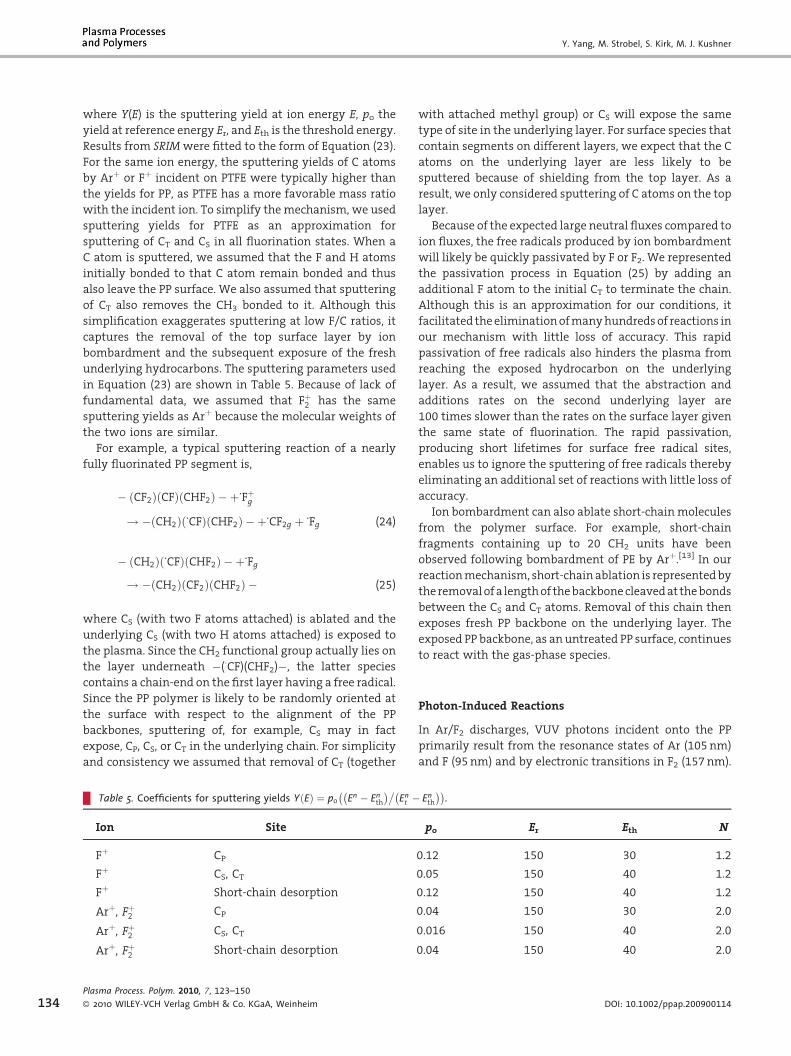
where Y(E) is the sputtering yield at ion energy E, po the
yield at reference energy Er, and Eth is the threshold energy.
Results from SRIMwere fitted to the form of Equation (23).
For the same ion energy, the sputtering yields of C atoms
by Arþ or Fþ incident on PTFE were typically higher than
the yields for PP, as PTFE has a more favorable mass ratio
with the incident ion. To simplify themechanism, we used
sputtering yields for PTFE as an approximation for
sputtering of CT and CS in all fluorination states. When a
C atom is sputtered, we assumed that the F and H atoms
initially bonded to that C atom remain bonded and thus
also leave the PP surface. We also assumed that sputtering
of CT also removes the CH3 bonded to it. Although this
simplification exaggerates sputtering at low F/C ratios, it
captures the removal of the top surface layer by ion
bombardment and the subsequent exposure of the fresh
underlying hydrocarbons. The sputtering parameters used
in Equation (23) are shown in Table 5. Because of lack of
fundamental data, we assumed that Fþ2 has the same
sputtering yields as Arþ because the molecular weights of
the two ions are similar.
For example, a typical sputtering reaction of a nearly
fully fluorinated PP segment is,
Tab
Ion
Fþ
Fþ
Fþ
Arþ
Arþ
Arþ
Plasma
� 2010
� CF2ð Þ CFð Þ CHF2ð Þ � þ.Fþg
! � CH2ð Þ .CFð Þ CHF2ð Þ � þ.
CF2g þ .Fg (24)
. .
� CH2ð Þ CFð Þ CHF2ð Þ � þ Fg! � CH2ð Þ CF2ð Þ CHF2ð Þ � (25)
where CS (with two F atoms attached) is ablated and the
underlying CS (with two H atoms attached) is exposed to
the plasma. Since the CH2 functional group actually lies on
the layer underneath �(�CF)(CHF2)�, the latter species
contains a chain-end on the first layer having a free radical.
Since the PP polymer is likely to be randomly oriented at
the surface with respect to the alignment of the PP
backbones, sputtering of, for example, CS may in fact
expose, CP, CS, or CT in the underlying chain. For simplicity
and consistency we assumed that removal of CT (together
le 5. Coefficients for sputtering yields Y Eð Þ ¼ po En � Enth� ��
Enr ���
Site
CP
CS, CT
Short-chain desorption
, Fþ2 CP
, Fþ2 CS, CT
, Fþ2 Short-chain desorption
Process. Polym. 2010, 7, 123–150
WILEY-VCH Verlag GmbH & Co. KGaA, Weinheim
with attached methyl group) or CS will expose the same
type of site in the underlying layer. For surface species that
contain segments on different layers, we expect that the C
atoms on the underlying layer are less likely to be
sputtered because of shielding from the top layer. As a
result, we only considered sputtering of C atoms on the top
layer.
Because of the expected large neutral fluxes compared to
ion fluxes, the free radicals produced by ion bombardment
will likely be quickly passivated by F or F2. We represented
the passivation process in Equation (25) by adding an
additional F atom to the initial CT to terminate the chain.
Although this is an approximation for our conditions, it
facilitated theeliminationofmanyhundredsof reactions in
our mechanism with little loss of accuracy. This rapid
passivation of free radicals also hinders the plasma from
reaching the exposed hydrocarbon on the underlying
layer. As a result, we assumed that the abstraction and
additions rates on the second underlying layer are
100 times slower than the rates on the surface layer given
the same state of fluorination. The rapid passivation,
producing short lifetimes for surface free radical sites,
enables us to ignore the sputtering of free radicals thereby
eliminating an additional set of reactions with little loss of
accuracy.
Ion bombardment can also ablate short-chainmolecules
from the polymer surface. For example, short-chain
fragments containing up to 20 CH2 units have been
observed following bombardment of PE by Arþ.[13] In our
reactionmechanism, short-chainablation is representedby
theremovalofa lengthof thebackbonecleavedat thebonds
between the CS and CT atoms. Removal of this chain then
exposes fresh PP backbone on the underlying layer. The
exposed PP backbone, as an untreated PP surface, continues
to react with the gas-phase species.
Photon-Induced Reactions
In Ar/F2 discharges, VUV photons incident onto the PP
primarily result from the resonance states of Ar (105nm)
and F (95nm) and by electronic transitions in F2 (157nm).
Enth��.
po Er Eth N
0.12 150 30 1.2
0.05 150 40 1.2
0.12 150 40 1.2
0.04 150 30 2.0
0.016 150 40 2.0
0.04 150 40 2.0
DOI: 10.1002/ppap.200900114

Fluorine Plasma Treatments of Poly(propylene) Films, 2 . . .
Quantum yields for photon-induced reactions on PP are
available for the resonance transition inXeat147nm.[22–24]
For example, VUV irradiation abstracts H2 from a PP
backbone and forms a double bond,
Plasma
� 2010
� CH2ð Þ CHð Þ CH3ð Þ � þhn 147 nmð Þ
! H2g þ� CHð Þ ¼ Cð Þ CH3ð Þ�
p ¼ 0:25
(26)
where p is the quantum yield.[22] For partially fluorinated
PP,weassumed thatH2will beextracted if both tertiaryand
secondary H atoms are available on a PP unit; F2 will be
extracted if all tertiary and secondary H atoms have been
substituted by F atoms; and HF will be extracted for other
cases.
VUV irradiation can also sever C�C bonds and allow for
disproportionation reactions. Dorofeev et al. determined
that a representative process is,
2 � CH2ð Þ CHð Þ CH3ð Þ�½ � þ hn 147 nmð Þ
! � CH2ð Þ CH2ð Þ CH3ð Þ þ CH2ð Þ
¼ Cð Þ CH3ð Þ�
p ¼ 0:25
(27)
where two chain-ending units are produced.[22] The
quantum yield for this process is about 0.25 at
147nm.
The ablation ofmethyl radicals can also occur underVUV
irradiation,
� CH2ð Þ CHð Þ CH3ð Þ � þhn 147 nmð Þ
! � CH2ð Þ CHð Þ�� þ CH3g
p ¼ 0:025
(28)
where the yield is smaller than ablation of H2 by an order
of magnitude.[22]
With the increase in fluorination, the quantumyields for
thesephoton-surface reactions decrease due to the stronger
C�F bonds and the steric hindrance of the F atoms. For
example, the quantum yield for F abstraction from PTFE at
147nm is only about 0.0025. The hierarchy for photon-
surface reaction probabilities used in themodel is shown in
Table 6. We used the measured yields at 147nm as
approximations for thoseat157nm.Toobtain thequantum
yields at 95 and 105nm,we further assumed that quantum
yields are linearly proportional to photon energy. In theAr/
F2 discharges considered here, the fluxes of photons onto
the filmare usually several orders ofmagnitude lower than
Process. Polym. 2010, 7, 123–150
WILEY-VCH Verlag GmbH & Co. KGaA, Weinheim
thefluxes of F atoms. Consequently, the ablation of singleH
or F atoms by VUV photons was neglected because H
abstraction by F atoms and passivation of free radicals by F
and F2 proceed at rates that are expected to be orders of
magnitude larger. Photon induced crosslinking was also
neglected for the same reason.
Double bonds resulting from the VUV illumination are
likely to be rapidly passivated by F atoms and F2molecules.
To estimate this probability, comparisons were made
between rates of gas-phase double bond passivation
reactions in thehigh-pressure limit and rates of passivation
of free radicals [Equation (16)],
C2H4 þ F� ! C2H4F�
k ¼ 1:7� 10�10 cm3 s�1 45½ �(29)
In general, the rates of double bond passivation by F atoms
are similar to the rates of F passivation of free radicals.
Consequently, we set the probability for passivation of
double bonds by F atoms to 10�4 regardless of fluorination
state.
Plasma Properties of Ar/F2 Plasma
A schematic of the reactor implemented in the model is
shown in Figure 4. This is a two-dimensional simulation in
Cartesian coordinates. The square electrodes are 46 cm on a
side (and so the depth perpendicular to the plane of the
simulation is 46 cm). The upper electrode is powered at
10MHz through a blocking capacitor and the lower
electrode is grounded. Both electrodes serve as shower-
heads with discrete nozzles for gas introduction and are
surroundedbydielectrichaving e/e0¼ 8.0.All other surfaces
in the reactor are groundedmetal including the pump port
at the right boundary of the reactor. The gap between the
electrodes is 2.54 cm. The PP film is placed in the middle of
the reactor. Unprocessed PP film is fed from the left side of
the reactor and thefilmmoves fromleft to right through the
reactor, thereby achieving continuous treatment. The film
is treated as an electrically floating dielectric. The base
conditions are Ar/F2¼ 60/40 (by volume) at 500 mTorr, a
flow rate of 600 sccm, and a power deposition of 600W
(0.28W � cm�2 of electrode area or 0.11W � cm�3 of inter-
electrode volume). The applied voltage is adjusted to yield
this power. The web moves at 9 cm � s�1, which produces a
6 s residence time in the reactor.
The resulting rf cycle-averaged electron temperature (Te),
ionization by bulk electrons (Sb), and ionization by
secondary beam electrons (Seb) for these conditions are
shown in Figure 4b–d. For 600W, the applied rf potential is
296V inamplitude, producing adc bias of 11V. This slightly
positive dc bias is developed as the area of the powered
www.plasma-polymers.org 135

Y. Yang, M. Strobel, S. Kirk, M. J. Kushner
Table 6. Probabilities for photon-surface reactions.
Processa) Probability
95 105 157
Extraction and double bond formation nm
�(CH2)(CH)(CH3)�þhn!H2þ�(CH)¼(C)(CH3)� 0.41 0.375 0.25
�(CH2)(CF)(CH3)�þhn!HFþ�(CH)¼(C)(CH3)� 0.41 0.375 0.25
�(CHF)(CF)(CH3)�þhn! F2þ�(CH)¼(C)(CH3)� 0.013 0.012 0.008
Scission and disproportionation
�(CH2)(CH)(CH3)�þhn!�(CH2)(CH2)(CH3) 0.21 0.19 0.125
�(CH2)(CH)(CH3)�þhn! (CH2)¼(C)(CH3)� 0.21 0.19 0.125
�(CHF)(CF)(CH3)�þhn!�(CHF)(CF2)(CH3) 0.005 0.0045 0.003
�(CHF)(CF)(CH3)�þhn! (CHF)¼(C)(CH3)� 0.005 0.0045 0.003
Abaltion of CP
�(CH2)(CH)(CH3)�þhn!�CH3gþ�(CH2)(CH�)� 0.041 0.0375 0.025
a)Only example processes are shown here. All permutations and combination of surface species are included in the reaction mechanism.
Figure 4.Geometry for the reactor used in themodel and plasma properties for the basecase (Ar/F2¼60/40, 500 mTorr, 600 sccm, 600W at 10MHz and web speed of9 cm � s�1). (a) Geometry, (b) electron temperature, (c) ionization by bulkelectrons, Sb, (d) ionization by sheath-accelerated beam electrons, Seb. The feed andcollector rolls are not included here as they are outside of the plasma volume. The PPfilm enters through the left side of the reactor and translates to the right. Theintervening dielectric produces a layered structure in Te. The bulk ionization sourcepeaks near the electrode edges because of the elevated Te from electric field enhance-ment. The bulk and beam ionization are plotted on log scales over two decades. Themaximum value or range of values in each frame is noted.
136Plasma Process. Polym. 2010, 7, 123–150
� 2010 WILEY-VCH Verlag GmbH & Co. KGaA, Weinheim
electrode is equal to that of grounded
surface and the plasma is highly electro-
negative. TheTe in thebulkplasma is3 eV.
The intervening dielectric produces a
layered structure in the Te, higher above
thedielectric adjacent to the sheath at the
upper electrode, as a result of the dc bias
and larger sheath potential. Because of
the large capacitance of the thin PPfilm, it
acquires a floating potential, though not
instantaneously during the rf cycle. This
allows for some sheath oscillation at the
sheathboundary andahigherTe of 3.5 eV.
ThedistributionofTe in thebulkplasma is
more uniform as a result of Ohmic
heating and a large thermal conductivity.
Localmaxima inTe occurnear the edgesof
the electrodes because of electric field
enhancement.
With Te nearly uniform in the bulk
plasma, the rate of ionization by bulk
electrons largely follows the electron
density and has a maximum value of
9.8� 1017 cm�3 � s�1. Ionization sources
peak near the electrode edges because
of the elevated Te resulting from the
electric field enhancement. With the
DOI: 10.1002/ppap.200900114

Fluorine Plasma Treatments of Poly(propylene) Films, 2 . . .
Figure 5. Plasma properties and neutral densities for the base case (Ar/F2¼60/40,500mTorr, 600 sccm, 600Wat 10MHz andweb speed of 9 cm � s�1). (a) Electron density,(b) F� density, (c) cycle averaged plasma potential, (d) total positive ion density, (e) [F2],and (f) [F]. Loss of F� is dominated by volumetric processes (associative detachment andion–ion neutralization,) and there are time averaged electrostatic traps for F�. Electronand F� densities largely mirror the bulk ionization source. The uniform [F] is due to theuniform Te and rapid F atom diffusion. The electron and ion densities are plotted on logscales over two decades. The maximum value or range of values in each frame is noted.
sheath 1–2mm thick, and the mean free
path for electron collisions being longer
than the sheath width, secondary elec-
trons are launched into the bulk plasma
from theupper electrodewith essentially
the instantaneous sheath potential. The
sheath potential on the upper electrode
has a maximum value of approximately
Vrf–Vdc or 285V. The mean free path for
electrons at this energy is about 1.0 cm,
close to electrode-film spacing of 1.3 cm.
As a result, the secondary electrons
undergo at most one or two collisions
and produce little ionization (maximum
value 2.6� 1015 cm�3s�1) before inter-
secting and charging the film.
The cycle-averaged electron density
[e], negative ion density [F�], total
positive ion density [total ions], and
plasma potential are shown in Figure
5a–d. [e] with a peak value of
1.3� 1010 cm�3 closely mirrors the bulk
ionization source and has a maximum
near the edge of the electrode. F2 rapidly
attaches electrons and the mean free
path of electrons for attachment is about
2 cm, commensurate to the electrode-
film gap. Electrons are therefore as likely
tobe lostbyattachmentasbydiffusion to
surfaces. Negative ions cannot climb the
ambipolar potential barrier and so are restricted to the core
of the plasma. As a result, the loss of negative ions is
dominated by volumetric processes (ion-ion neutralization
and associative detachment) and there are time-averaged
electrostatic traps for negative ions in the bulk plasma. The
end result is that the peak value of [F�] is 2.0� 1011 cm�3
and the reactor-averaged electronegativity ([F�]/[e]) is
about 15. Note that the spatial locations at which the
electron, negative ion and positive ion densities have their
peakvaluesaredifferent.Asa result, theirmaximumvalues
maydiffer evenwhilequasi-neutrality isbeingmaintained.
The cycle-averaged densities of F2 and F are shown in
Figure 5e,f. The reactor averaged [F2] and [F] are 3.9� 1015
and 2.0� 1015 cm�3, respectively, representing a dissocia-
tion fraction of 0.2. The distribution of F atoms is fairly
uniform because of the low reactivity of F atoms on
previously passivated surfaces. Injection of the Ar/F2mixture through discrete nozzles produces local minima
in [F], where the feedstock gases jet into the reactor, and
corresponding peaks in the feedstock density. [F2] also has a
rather uniform distribution with a slightly lower value in
the center of the plasma where the dissociation rates are
higher. The higher value of [F2] near the electrodes or the PP
results from associative desorption.
Plasma Process. Polym. 2010, 7, 123–150
� 2010 WILEY-VCH Verlag GmbH & Co. KGaA, Weinheim
As discussed above, surface reactions of the PP sheet
with the Ar/F2 plasma produce gas species such as HF
(from F abstraction reactions) and fragments of the PP
chain (CnHm from ion and photon bombardment). HF is
relatively stable—all chemical reactions of HFwith the gas
phase species in this system are highly endothermic. On a
reactor averaged basis, the HF density is 1.8� 1012 cm�3,
sufficiently small to neglect the consequences of
electron impact reactions with HF on electron transport.
Hydrocarbon fragments of the PP chain from ion and
photon bombardment were neglected in the gas
phase reaction mechanism due to their low rates of
production. The most likely reactions they would undergo
are the same as on the surface, H atom abstraction by
F atoms, which would not significantly affect the fluxes
to the substrate.
Plasma Fluorination of PP
Surface Characteristics for the Base Case
With the PP immersed in the plasma, both sides of the film
are fluorinated. For purposes of presentation, the path
www.plasma-polymers.org 137

Y. Yang, M. Strobel, S. Kirk, M. J. Kushner
Figure 6. Fluxes incident on the PP film for the base case (Ar/F2¼60/40, 500 mTorr, 600 sccm, 600W at 10MHz and webspeed of 9 cm � s�1). (a) Neutrals and ions and (b) VUV photons.Fluxes of F and F2 are generally four orders of magnitude largerthan ion fluxes (Arþ, Fþ, Fþ2 ). Photon fluxes are several orders ofmagnitude lower than the fluxes of neutrals and ions.
138
followed when plotting surface quantities starts at the left
end of the reactor on the bottom side of the PP film, then
turns the corner on the right end, and finally continues on
thesamesideof thePPfilm,back tothe leftendof thereactor
(see Figure 4a). Following this path, fluxes of neutrals, ions,
and photons incident on the PP film for the base case are
shown in Figure 6. The fluxes of F and F2 are essentially
uniform on both sides of the film. As the dissociation
fraction of F2 was found to be 0.2, the flux of F2,
4.3� 1019 cm�2 � s�1, is about 1.5 times that of F. These
fluxes of neutrals are four orders of magnitude larger than
those of the ions (Arþ, Fþ, Fþ2 ). As such, the influence of ions
will be dominantly through processes that have threshold
energies (such as sputtering) as opposed to the competing
contributions to abstraction or passivation. The flux of Arþ
(1.5� 1015 cm�2 � s�1) exceeds that of Fþ2 (by three times)
and Fþ (by six times), resulting in part from the highermole
fraction of Ar in the feedstock and the lower ionization
potential of Ar (15.8 eV) relative to F (17.4 eV), while being
commensurate to F2 (15.7 eV).
Inadditiontodirect ionization,multistep ionization from
excited states is an appreciable source of Arþ and provides
for themore uniformdistribution of Arþ. The top of the film
(inFigure4a) faces thepoweredelectrodeandsohas line-of-
sight to the electric-field-enhanced corners of the electro-
des. The peaks in the flux of Fþ2 on the top of the film,
resulting dominantly from single-step electron-impact
ionization, reflects the higher ionization sources at the
edge of the electrodes. The flux of Arþ, having more
distributed sources due tomultistep ionization, has smaller
peaks.
Thefluxes ofVUVphotons are a few times1013 cm�2 � s�1
andthusare106 timessmaller thanthatof theFfluxand102
times smaller than that of the ion flux. As such, photons are
of secondary importance indetermining the compositionof
the surface with the exception of processes unique to
photons, such as initiating double-bond formation. The
edge effect on the top of the film is more severe for the
photon fluxes. Although there is some trapping of the VUV
radiation (a trapping factor of 5.8 for resonance radiation
from F and 5.0 for Ar), much of the VUV flux arrives at the
substrate following line-of-sight transport from its source,
and so mirrors the larger source functions at the edges.
The energy and angular distributions (IEADs) summed
for all ions incident on the top and bottom PP surfaces are
shown in Figure 7. The corresponding plasma potential at
30 cmisalso shown inFigure7atapproximately thepeakof
the anodic cycle (phase w¼p/2), peak of the cathodic cycle
(w¼ 3p/2), and the zero crossings in the rf voltage displaced
byVdc. The rf amplitude is296Vtodeliver apowerof 600W.
The top side of the film faces the powered electrode. In spite
ofbeingafloatingdielectric, the capacitanceof thePPfilmis
large enough that a significant rf drift current is collected
with an accompanying cathodic sheath on the top side
Plasma Process. Polym. 2010, 7, 123–150
� 2010 WILEY-VCH Verlag GmbH & Co. KGaA, Weinheim
when the top electrode is the anode. During the cathodic
part of the cycle for the top electrode, the film discharges
and there is virtually no sheath. As the pressure is relatively
high (500mTorr), charge-exchange collisions (with collision
frequencies on the order of 107 s�1) effectively degrade
IEADs in energy.With the exception of the increased energy
due to the positive dc bias, the IEAD incident on the bottom
side of the PP is similar to that on the top side.
If the film were stationary in the discharge, film surface
properties would be a function of position in the discharge
reflecting the spatial distribution of reactants. With a
moving web, each site on the film averages the spatial
distribution of fluxes as that site moves under the fluxes
from entry to exit points. The film is ultimately uniformly
processed with a surface composition given by those sites
exiting the reactor. Exceptions include differences in fluxes
incident on the top and bottom sides of the film. This is not
to say that the spatial distributions of the fluxes are not
important. As the surface composition of the film changes,
so does the reactivity of the film. For example, a given ratio
of radical-to-ion fluxes at the entry of the film to the reactor
may elicit a different response than that at the exit of the
reactor since the surface composition will have changed.
Having said that, the trends in surface coverages on the top
and bottom sides of the film are largely the same due to the
magnitudes of the neutral fluxes and IEADs being similar.
Typically, the PP film surface compositions at the exit of the
DOI: 10.1002/ppap.200900114

Fluorine Plasma Treatments of Poly(propylene) Films, 2 . . .
Figure 7. IEADs striking the PP surfaces for the base case and thecorresponding plasma potential (Ar/F2¼60/40, 500 mTorr,600 sccm, 600W at 10MHz and web speed of 9 cm � s�1).(a) IEADs incident on the bottom surface, (b) IEADs incident onthe top surface, and (c) plasma potential as a function of height atdifferent phases during an rf cycle (position¼ 30 cm). The con-tours for the IEADs span two decades using a log scale.
Figure 8. Coverages of sites on the bottom side of the PP film forthe base case (Ar/F2¼60/40, 500 mTorr, 600 sccm, 600W at10MHz and web speed of 9 cm � s�1) as a function of position.(a, b) First 10 cm (1.1 s) of the film entry into the reactor.(c, d) Between 10 (1.1 s) and 54 cm (the end of the film, a residencetime of 6 s) The surface species with largest fractional coverage atthe exit of the film from the reactor is the perfluorinated PP unitwith crosslinking on CP [denoted by (CF2)(CF)(CRF2)].
reactor differ by less than 10% between the top and bottom
surfaces. As such, surface properties will be discussed for
only the bottom side.
The coverage of surface species (PP units in various
fluorinationstates) on thebottomsideof thefilmareshown
in Figure 8a,b for the first 10 cm of the film travel into the
reactor. This corresponds to a treatment time of 1.1 s. The
sequential nature of the fluorination is shown by
the change in fractional surface coverages as a function
of distance (which corresponds to time). In the first 2 cm,
the surface species [aside from the untreated PP,
(CH2)(CH)(CH3)] having the largest coverages are those
containing a single free radical on CP CH2ð Þ CHð Þ CH�2
� �� �, CS
CH�ð Þ CHð Þ CH3ð Þ½ �, and CT CH2ð Þ C�ð Þ CH3ð Þ½ �. These corre-
Plasma Process. Polym. 2010, 7, 123–150
� 2010 WILEY-VCH Verlag GmbH & Co. KGaA, Weinheim
spond to products of the first H-abstraction reactions. The
sum of the fractional coverage of PP units that have
unreacted alkyl sites reaches a maximum of about 0.27
between 1 and 2 cm (0.11–0.22 s residence time). This
represents �0.09 of all carbon atoms. Alkyl sites with a
dangling bond on CS or CP have larger coverages than that
of CT as a result of the fact that the first abstraction ofHby F
atoms does not discriminate by site. Since there are larger
numbers of secondary and primary H atoms, CS or CP will
have more alkyl sites.
Following these first abstractions, crosslinking and F-
atom addition reactions passivate the alkyl sites and the
fractional coverages of alkyl sites monotonically decrease
beyond 2 cm (0.22 s). This decrease correlates with an
www.plasma-polymers.org 139

Y. Yang, M. Strobel, S. Kirk, M. J. Kushner
140
increase in the fractional coverages of sites having a
single F atom and where CP, CS, or CT are crosslinked
[(CH2)(CR)(CH3), (CRH)(CH)(CH3), (CH2)(CH)(CRH2)]. The sum
of the coverages of these crosslinked sites peaks at about
0.15 between 4 and 6 cm (0.44–0.67 s). Further fluorination,
and ion and photon activated processes, monotonically
decrease these fully hydrogenated crosslinked sites beyond
6 cm (0.67 s).
The decrease in fully hydrogenated alkyl sites also maps
ontoan increase in the fractional coveragesof sites inwhich
a single F atomhas been substituted for H in the starting PP
[(CH2)(CH)(CH2F), (CHF)(CH)(CH3), (CH2)(CF)(CH3)]. The sum
of these singly fluorinated sites peaks at about 0.26
between 4 and 6 cm (0.44–0.67 s). The fluorination of these
alkyl sites by F and F2 compete with ion bombardment or
photolysis, which potentially removes the F atom, and
abstraction, which produces new free radicals. The
abstraction and addition reactions also replace H atoms
with F atomson fully hydrogenated crosslinked sites and so
that surface species such as (CH2)(CH)(CRHF) and
(CRF)(CH)(CH3) are produced. The fractional coverage of
these species is less than that of the singly fluorinated sites
without crosslinking and peak at about 0.03 between 10
and15 cm(1.1–1.7 s), as showninFigure8bandd. (Note that
the parenthetical times following distances into the reactor
represent the residence time of the film in the reactor at
those points.)
The abstraction of the second H atom, which produces a
free radical in a singly fluorinated backbone, potentially
generates a large number of species. For example, the
second H abstraction after a first fluorination on CP can
result in three species: CH2ð Þ CHð Þ CHF�ð Þ, CH2ð Þ C�ð Þ CH2Fð Þ,and CH�ð Þ CHð Þ CH2Fð Þ. These radicals arequicklypassivated,producing doubly fluorinated sites that increase to frac-
tional coverages of 0.01–0.1 by 10 cm (1.1 s)
[(CH2)(CH)(CHF2) and (CF2)(CH)(CH3) in Figure 8b]. Con-
current to the increase in the coverages of sites having
radicals or F atoms, the coverage of pure hydrocarbon sites
[(CH2)(CH)(CH3)] undergoes an exponential decrease.
Within the first 10 cm (1.1 s) the fractional coverage of
the untreated PP decreases to 0.03.
Due to the steric hindrance and the decrease in reaction
rates with increase in fluorination, the fluorination to
higher F/C ratios proceeds at a slower rate. This is shown in
Figure 8c,d for surface coverages between 10 (1.1 s) and
54 cm (the exit of the reactor, corresponding to a residence
time of 6 s). The doubly fluorinated sites on the CP and CS
sites, [(CF2)(CH)(CH3), (CH2)(CH)(CRF2)], have maximum
coverage between 10 and 20 cm (1.1–2.2 s). As additional
abstraction and passivation reactions take place, a large
variety of species are produced. For example, the triply
fluorinated sites having the earliest and largest fractional
coverage is (CF2)(CF)(CH3), peaking at 30 cm (3.3 s). Follow-
ing this sequence of abstraction and fluorination, the fully
Plasma Process. Polym. 2010, 7, 123–150
� 2010 WILEY-VCH Verlag GmbH & Co. KGaA, Weinheim
fluorinated PP unit [(CF2)(CF)(CF3)] achieves a fractional
coverage of 0.07 at the exit. The precursors for the fully
fluorinated sites are dominantly (CF2)(CF)(CHF2) and
(CF2)(CH)(CF3). As the fully fluorinated sites do not
significantly react with neutral gas-phase species, they
lose C and F atoms dominantly by ion or photon
bombardment.
Crosslinking consumes two adjacent alkyl groups and so
eliminates the possibility of passivation by F or F2. Cross-
linking is therefore in competition to the fluorination
process. This role of cross-linking in this competition is
indicated by the large coverage of (CF2)(CF)(CRF2) at the exit
of the reactor (0.15 at 54 cm or 6 s). Other crosslinked PP
sites having relatively large coverages at 54 cm are
(CF2)(CH)(CRF2), (CRF)(CF)(CF3), and (CF2)(CR)(CF3), with
fraction coverages ranging from 0.05 to 0.12. At the exit
of the reactor, themodeled F/C ratio of the PP surface is 1.39.
The more slowly fluorinated sites [e.g., (CF2)(CH)(CF3),
(CF2)(CH)(CRF2)] take longer to fully fluorinate because of
the reduction in rates of bothHabstraction andpassivation
accounting for diffusion of gas-phase radicals into the film.
As discussed earlier, the CH groups in (CF2)(CH)(CF3) and
(CF2)(CH)(CRF2) are located on theunderlying PPbackbones,
thereby having more resistance to H abstraction. The
dominant surface species havingH that is left on the top PP
surface after 6 s is (CF2)(CF)(CHF2). The last HP is the most
difficult tobeabstractedbecauseofdeactivationeffects and
steric hindrance. At the exit of the film, only about 0.04 of
the original inventory ofHatomsare left on the top surface.
All other H atoms were abstracted by F atoms with the
resulting radical sites either passivated by a F atom or
crosslinked.
The consequences of ion and photon bombardment,
though small as a fraction of the total reactivity, tend to
producemore stable species that integrate in density as the
filmmoves through the plasma. The end result is that those
species have non-negligible densities at the exit of the
reactor. As with the neutral channels, reactions of ions and
photons are capable of producing many hundreds of other
types of sites. Although any single site has a small density,
cumulativedensities canbenon-negligible. Thecumulative
contributions of reactions initiated by ions and photons to
fluorination are shown in Figure 9a. The separate contribu-
tions from ions and photons are shown in Figure 9b,c. The
total coverage of surface species resulting from both ions
and photons having only 1 F atom peaks at 10�3 at 12 cm
(1.3 s) and decreases monotonically thereafter. The total
coverages of surface species containing 3–6 F atoms
increase monotonically in the first 48 cm while the total
coverages of species containing 2 F atoms largely remain
constant at 2� 10�3.
Beyond 48 cm (5.3 s), the fluxes of ions and photons
incident on the PP film quickly decrease as the PP film
translates out of the discharge. Due to the rapid neutral
DOI: 10.1002/ppap.200900114
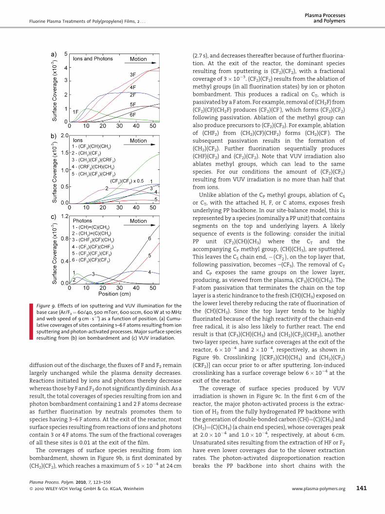
Fluorine Plasma Treatments of Poly(propylene) Films, 2 . . .
Figure 9. Effects of ion sputtering and VUV illumination for thebase case (Ar/F2¼60/40, 500 mTorr, 600 sccm, 600W at 10MHzand web speed of 9 cm � s�1) as a function of position. (a) Cumu-lative coverages of sites containing 1–6 F atoms resulting from ionsputtering and photon-activated processes. Major surface speciesresulting from (b) ion bombardment and (c) VUV irradiation.
diffusion out of the discharge, the fluxes of F and F2 remain
largely unchanged while the plasma density decreases.
Reactions initiated by ions and photons thereby decrease
whereas thosebyFandF2donotsignificantlydiminish.Asa
result, the total coverages of species resulting from ion and
photon bombardment containing 1 and 2 F atoms decrease
as further fluorination by neutrals promotes them to
species having 3–6 F atoms. At the exit of the reactor, most
surface species resulting fromreactions of ionsandphotons
contain 3 or 4 F atoms. The sum of the fractional coverages
of all these sites is 0.01 at the exit of the film.
The coverages of surface species resulting from ion
bombardment, shown in Figure 9b, is first dominated by
(CH2)(CF2), which reaches a maximum of 5� 10�4 at 24 cm
Plasma Process. Polym. 2010, 7, 123–150
� 2010 WILEY-VCH Verlag GmbH & Co. KGaA, Weinheim
(2.7 s), and decreases thereafter because of further fluorina-
tion. At the exit of the reactor, the dominant species
resulting from sputtering is (CF2)(CF2), with a fractional
coverage of 3� 10�3. (CF2)(CF2) results from the ablation of
methyl groups (in all fluorination states) by ion or photon
bombardment. This produces a radical on CT, which is
passivatedbyaFatom. Forexample, removal of (CH2F) from
(CF2)(CF)(CH2F) produces (CF2)(CF�), which forms (CF2)(CF2)
following passivation. Ablation of the methyl group can
also produce precursors to (CF2)(CF2). For example, ablation
of (CHF2) from (CH2)(CF)(CHF2) forms (CH2)(CF�). The
subsequent passivation results in the formation of
(CH2)(CF2). Further fluorination sequentially produces
(CHF)(CF2) and (CF2)(CF2). Note that VUV irradiation also
ablates methyl groups, which can lead to the same
species. For our conditions the amount of (CF2)(CF2)
resulting from VUV irradiation is no more than half that
from ions.
Unlike ablation of the CP methyl groups, ablation of CS
or CT, with the attached H, F, or C atoms, exposes fresh
underlying PP backbone. In our site-balance model, this is
represented by a species (nominally a PP unit) that contains
segments on the top and underlying layers. A likely
sequence of events is the following: consider the initial
PP unit (CF2)(CH)(CH3) where the CT and the
accompanying CP methyl group, (CH)(CH3), are sputtered.
This leaves the CS chain end, � CF�2� �
, on the top layer that,
following passivation, becomes –(CF3). The removal of CT
and CP exposes the same groups on the lower layer,
producing, as viewed from the plasma, (CF3)(CH)(CH3). The
F-atom passivation that terminates the chain on the top
layer is a steric hindrance to the fresh (CH)(CH3) exposed on
the lower level thereby reducing the rate of fluorination of
the (CH)(CH3). Since the top layer tends to be highly
fluorinated because of the high reactivity of the chain-end
free radical, it is also less likely to further react. The end
result is that (CF3)(CH)(CH3) and (CH2)(CF2)(CHF2), another
two-layer species, have surface coverages at the exit of the
reactor, 6� 10�4 and 2� 10�4, respectively, as shown in
Figure 9b. Crosslinking [(CRF2)(CH)(CH3) and (CH2)(CF2)
(CRF2)] can occur prior to or after sputtering. Ion-induced
crosslinking has a surface coverage below 6� 10�4 at the
exit of the reactor.
The coverage of surface species produced by VUV
irradiation is shown in Figure 9c. In the first 6 cm of the
reactor, the major photon-activated process is the extrac-
tion of H2 from the fully hydrogenated PP backbone with
the generation of double-bonded carbon (CH)¼(C)(CH3) and
(CH2)¼(C)(CH3) (a chain end species), whose coverages peak
at 2.0� 10�4 and 1.0� 10�4, respectively, at about 6 cm.
Unsaturated sites resulting from the extraction of HF or F2have even lower coverages due to the slower extraction
rates. The photon-activated disproportionation reaction
breaks the PP backbone into short chains with the
www.plasma-polymers.org 141

Y. Yang, M. Strobel, S. Kirk, M. J. Kushner
Figure 10. Consequences of crosslinking for the base case (Ar/F2¼60/40, 500 mTorr, 600 sccm, 600W at 10MHz and webspeed of 9 cm � s�1) as a function of position. (a) Major crosslinkedspecies and (b) coverages of the sum of PP unit sites withcrosslinked CP, CS, and CT.
142
generation of chain-ending species (all species except
(CH)¼(C)(CH3) in Figure 9c). The sum of the coverages of
these chain-ending species is about 0.003 at the exit. These
relatively low coverages are caused by the lowmagnitudes
ofphotonfluxesas comparedwith thatofneutrals and ions.
A secondary contributing cause to these low coverages is
that these chain-ending species are more rapidly removed
by ion and photon bombardment because of lower surface
binding energies. (To ablate these species, only one C�C
bond needs to be broken.)
The coverages of crosslinked species are shown in
Figure 10a. The free radicals on CP have larger crosslinking
probabilities as CP protrudes from the PP chain and so the
majority of crosslinking occurs on CP. At the exit of the
reactor, the fully fluorinated crosslinked CP [(CF2)(CF)(CRF2)]
has the largest (and still increasing) coverage at 0.15. This
increase largely results from the fluorination of the
precursors of (CF2)(CF)(CRF2) [(CF2)(CH)(CRF2), (CHF)(CF)
(CRF2), and (CF2)(CF)(CRHF)] after crosslinking. The coverage
of fully fluorinated crosslinked CS sites [(CRF)(CF)(CF3)]
and CT sites [(CF2)(CR)(CF3)] are 0.06 and 0.05 at 54 cm (6 s),
respectively.
Thecoveragesof thesumof crosslinkedCP,CS, andCT sites
are shown in Figure 10b. As number of sites with free
radicals decreases with increase in degree of fluorination,
most of crosslinking occurs in the first 30 cm (3.3 s). The exit
coverage of crosslinked CP sites (0.4) is about twice that of
the CS sites and four times that of the CT sites. The sum of
coverages of all crosslinked sites is about 0.73 at 54 cm (6 s),
which is about 70 times larger than the sum of all sites
formed due to ion and photon bombardment. Note that,
withinourmodeled system, crosslinkedCP is bonded to two
C atoms whereas CS and CT are bonded to 3 and 4C atoms,
respectively. Crosslinking, which connects free radicals to
adjacent C atoms, eliminates those bonds from being
fluorinated. Crosslinking therefore competes with the F
addition process, reducing themaximumpossible F/C ratio
from that of a fully fluorinated backbone. At the same time,
crosslinked sites are also more resistive to ion sputtering
andVUVphotolysis, processes that potentially removeC�F
bonds from the surface. So depending on operating
conditions, crosslinking could also be beneficial to the
fluorination process. For the process conditions investi-
gated in this work, the C/F ratio is generally decreased by
crosslinking.
The fractional coverages of CHand CFn functional groups
as a function of position are shown in Figure 11a. b–C refers
to C atoms that do not have C�F bonds but have
neighboring C atoms that do have C�F bonds. (This type
of species is discernable by XPS.) For example, (CH2) and
(CH3) are b–C species in (CH2)(CF)(CH3). The coverage of
singly fluorinated sites (CF) saturates in the first 10 cm
(residence time of 1.1 s) because of the rapid fluorination of
fully hydrogenated PP on the top layer. The fluorination of
Plasma Process. Polym. 2010, 7, 123–150
� 2010 WILEY-VCH Verlag GmbH & Co. KGaA, Weinheim
exposed PP on the underlying layers (producing CF) and the
fluorination of CF to higher states (consuming CF) proceed
at slower rates and are at a near equilibrium from 10 to
54 cm (1.1–6 s).
Thefluorinationfirst produces apeak coverage of 0.33 for
b–C sites at about 15 cm (1.6 s), decreasing thereafter. As a
result of steric hindrance, and electrophilic and diffusion
effects, the fractions of doubly and triply fluorinated sites
(CF2 and CF3) increase at slower rates. The fraction of CF2sites begins to saturate at the exit with a coverage of 0.37,
mainly consisting of perfluorinated CS and doubly
fluorinated CP sites. The general scaling for the F/C ratio,
shown in Figure 11b, is for amore rapid fluorination during
the first 15 cm (1.7 s), here to a value of 0.5, caused by the
single fluorination of fully hydrogenated PP. This relatively
rapid fluorination is followed by a slower approach toward
1.39 over the rest of the treatment. This latter, and slower,
fluorination results from the double and triple fluorination
of CS and CP sites and from the reactions with the lower-
layer PP chains.
A comparison of computed and experimental results for
functional group surface coverages after 6 s of treatment is
given in Table 7.[27] The prediction for F/C ratio agrees well
with the experiment. The discrimination between CH and
b–C inourmodel is somewhatarbitrarybecauseof thefinite
DOI: 10.1002/ppap.200900114

Fluorine Plasma Treatments of Poly(propylene) Films, 2 . . .
Figure 11. Functionalization of the bottom surface of the PP filmfor the base case (Ar/F2¼60/40, 500 mTorr, 600 sccm, 600W at10MHz and web speed of 9 cm � s�1) as a function of position.(a) Coverage of functional groups and (b) F/C ratio. The sequentialnature of the fluorination is shown by the successive dominanceof CFn with larger n as the film translates downstream.
number of configurations that we are able to model. If we
instead compare the sum of CH and b–C with experiment,
the agreement is better. The overestimation of CF and
underestimation of CF3 most likely originate from the
approximate manner in which F atom diffusion into the
surface layers is addressed.Another sourceofdiscrepancy is
that the F/C ratios obtained from the experimental ESCA
measurementsarise fromanalysis of theoutermost6–8nm
Table 7. Comparison of modeled surface coverage and experimental
Bonding Surface
6 s Treatment
Simulation Experim
CH 0.03 0.12
b–C 0.19 0.18
CF 0.29 0.26
CF2 0.37 0.34
CF3 0.12 0.10
F/C 1.38 1.41
a)Operating conditions: Ar/F2¼ 60/40, 600W, 500mTorr, web speed¼
Plasma Process. Polym. 2010, 7, 123–150
� 2010 WILEY-VCH Verlag GmbH & Co. KGaA, Weinheim
of the surface, which does not directly correspond to the
effective depth addressed in the simulation.
Exposure Time
To investigate the effects of longer exposure time on the
surface composition while minimizing the changing of
other parameters, the web speed was reduced to about
2 cm � s�1 to enable a residence time of 26 s to match
experiments.[27] Surface coverages for the major surface
species are shown in Figure 12a. At the exit of the reactor,
54 cm (26 s), the dominant surface species is (CF2)(CF)(CRF2),
the fully fluorinated PP unit with crosslinking on CP (0.41
coverage). The coverageof the fullyfluorinatedPPbackbone
(CF2)(CF)(CF3) reaches saturation at about 0.2 after 30 cm
(14.3 s). Other dominant surface species include fully
fluorinated PP unitswith crosslinking on CS [(CRF)(CF)(CF3)]
andCT [(CF2)(CR)(CF3)]. Sowitha longer exposure time,apart
from fluorination, the dominant changes in surface
composition still result from crosslinking.
As the hydrogenated PP becomes fluorinated, the rates of
fluorine addition decrease while the effects of ion and
photon bombardment continue to integrate. This integra-
tion is demonstrated by the nearly linear increase in
coverage of (CF2)(CF2) from 0 to 48 cm (0–23 s). Recall that
(CF2)(CF2) is formed by the ablation of themethyl group (for
all fluorination states). Beyond 48 cm (23 s), the film
translates out of the discharge and the fluxes of ions and
photons decrease rapidly so that the surface coverage of
(CF2)(CF2) remains nearly constant beyond 48 cm (23 s).
The fractional coverages of functional groups and the F/C
ratio are shown in Figure 12b,c. The persistence of small
fractions of CH (0.005) results from the ablation of CS and CTgroups by ion bombardment and the slow rates of
fluorination of the fresh underlying PP backbone. In the
absence of sputtering, photolysis, and crosslinking, we
would expect CF, CF2, and CF3 to each have 1/3 of the
ESCA F/C atomic ratios.
fractional coverage and F/Ca)
26 s Treatment
ent Simulation Experiment
0.01 0.02
0.04 0.10
0.35 0.30
0.42 0.45
0.18 0.13
1.73 1.57
9 cm � s�1 (6 s) and 2 cm � s�1 (26 s).
www.plasma-polymers.org 143
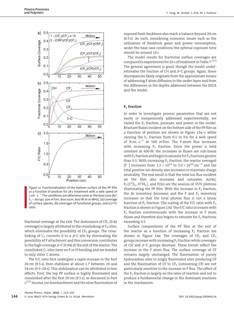
Y. Yang, M. Strobel, S. Kirk, M. J. Kushner
Figure 12. Functionalization of the bottom surface of the PP filmas a function of position for 26 s treatment with a web speed of2 cm � s�1. The conditions are otherwise same as the base case (Ar/F2¼60/40, 500mTorr, 600 sccm, 600W at 10MHz). (a) Coverageof surface species, (b) coverages of functional groups, and (c) F/Cratio.
144
fractional coverage at the exit. The dominance of CF2 (0.42
coverage) is largely attributed to the crosslinking of CP sites,
which eliminates the possibility of CF3 groups. The cross-
linking of CT converts it to a b–C site by eliminating the
possibility of F attachment and this conversion contributes
to the high coverage b–C (0.04) at the exit of the reactor. The
crosslinked CT sites have no F or H bonding and are bonded
to only other C atoms.
The F/C ratio first undergoes a rapid increase in the first
20 cm (9.5 s), then stabilizes at about 1.7 between 20 and
54 cm (9.5–26 s). This stabilization can be attributed to two
effects. First, the top PP surface is highly fluorinated and
crosslinked after the first 20 cm (9.5 s), as discussed in Part
I.[27] Second, ion bombardment and the slowfluorination of
Plasma Process. Polym. 2010, 7, 123–150
� 2010 WILEY-VCH Verlag GmbH & Co. KGaA, Weinheim
exposed fresh backbone also reach a balance beyond 20 cm
(9.5 s). As such, considering economic issues such as the
utilization of feedstock gases and power consumption,
under the base case conditions the optimal exposure time
should be around 10 s.
The model results for fractional surface coverages are
compared toexperiments for26 sof treatment inTable7.[27]
The general agreement is good, though the model under-
estimates the fraction of CH and b–C groups. Again, these
discrepancies likely originate from the approximatemeans
of addressing F atom diffusion to the under-layer and from
the differences in the depths addressed between the ESCA
and the model.
F2 Fraction
In order to investigate process parameters that are not
easily or inexpensively addressed experimentally, we
varied the F2 fraction, pressure, and power in the model.
Reactant fluxes incident on the bottom side of the PPfilmas
a function of position are shown in Figure 13a–c while
varying the F2 fraction from 0.1 to 0.6 for a web speed
of 9 cm � s�1 at 500 mTorr. The F-atom flux increases
with increasing F2 fraction. Since the power is held
constant at 600W, the increases in fluxes are sub-linear
withF2 fractionandbegintosaturate forF2 fractionsgreater
than 0.5. With increasing F2 fraction, the reactor averaged
[F�] increases from 1.2� 1010 to 3.0� 1010 cm�3 and the
total positive ion density also increases tomaintain charge
neutrality. The end result is that the total ion flux incident
on the film also increases and saturates. Ar(4s),
F2 C1Su;H1Pu
� �, and F(3s) are the sources of VUV photons
illuminating the PP film. With the increase in F2 fraction,
the Ar inventory decreases and the F and F2 inventory
increases so that the total photon flux is not a linear
function of F2 fraction. The scaling of the F/C ratio with F2fraction is shown in Figure 13d. The F/C ratio increaseswith
F2 fraction commensurate with the increase in F atom
fluxes and therefore also begins to saturate for F2 fractions
exceeding 0.5.
Surface compositions of the PP film at the exit of
the reactor as a function of increasing F2 fraction are
shown in Figure 14a. The coverages of CF2 and CF3groups increasewith increasing F2 fractionwhile coverages
of CH and b–C groups decrease. These trends reflect the
increase in the F atom flux. The surface coverage of CF
remains largely unchanged. The fluorination of purely
hydrocarbon sites to singly fluorinated sites producing CF
and the fluorination of CF to CF2 (consuming CF) are not
particularly sensitive to the increase in F flux. The effect of
the F2 fraction is largely on the rates of reaction and not to
produce a fundamental change in the dominant reactions
in the mechanism.
DOI: 10.1002/ppap.200900114

Fluorine Plasma Treatments of Poly(propylene) Films, 2 . . .
Figure 13. Fluxes incident on the bottom side of the PP film andcorresponding F/C ratios for F2 fractions of 10–60%. The con-ditions are otherwise same as the base case (500 mTorr,600 sccm, 600W at 10MHz and web speed of 9 cm � s�1). (a) Fflux, (b) total ion flux, (c) total photon flux, and (d) F/C ratio. TheF/C ratio at the exit increases with increase in F2 fraction but doesso sub-linearly with F2 fraction.
Figure 14. Surface compositions at the exit from the reactor onthe bottom side of the film and fluorination efficiency as afunction of F2 fraction. The conditions are otherwise same asthe base case (500 mTorr, 600 sccm, 600W at 10MHz and webspeed of 9 cm � s�1). (a) Fractional coverage of functional groups,(b) fractional coverage of total PP unit sites modified by ion andphoton bombardment, (c) h, fluorination efficiency and F/C ratio,and (d) IEDs. h decreases with increase in F2 fraction because ofthe less efficient fluorination as F/C increases.
Plasma Process. Polym. 2010, 7, 123–150
� 2010 WILEY-VCH Verlag GmbH & Co. KGaA, Weinheim
The fractional coverages of the sum of PP unit sites
modified by ion and photon bombardment and the sum of
crosslinked unit sites are shown in Figure 14b as a function
of F2 fraction. Ion fluxes increase with F2 fraction, but the
fraction of PP unit sites modified by ions and photons does
not monotonically increase with F2 fraction as there are
concurrent non-linear changes in the incident ion energies.
For example, the ion energy distributions (IEDs) are shown
in Figure 14d. The increase in F2 flux with increase in F2fraction reduces the average lifetime of sites with free
radicals by increasing the rate of passivation, thereby
www.plasma-polymers.org 145

Y. Yang, M. Strobel, S. Kirk, M. J. Kushner
146
decreasing radical densities. At the same time, the rate of
abstraction increases with increase in F atom flux, which
increases the density of sites with free radicals. So
increasing the F and F2 fluxes could either increase or
decrease the density of polymer radicals depending on the
state of fluorination of the surface. Since the rate of
formation of crosslinked sites scales with the square of the
density of radicals, the density of crosslinked sites could
either increase or decrease with increase in F2 fraction. For
our conditions, at the same fluorination state, the
probabilities for F-atom addition are generally larger than
those for F abstraction.Adding thepassivation causedbyF2,
the total free radical inventorydecreaseswith increase in F2fraction and so the fraction of crosslinked sites decreases
slightly with F2 fraction, as shown in Figure 14b.
To provide a relative estimate of the efficiency of the
fluorination process, we define the fluorination efficiency
as
Plasma
� 2010
h ¼ F=Cð Þ0F=Cð Þm
� 2 NS½ �fFt
(30)
where (F/C)0 is the ratio at the exit of the reactor and (F/C)mis the maximum ratio, which for PP is 2.
[NS]¼ 6� 1015 cm�2 is the density of H sites (six H atoms
per PP unit and 1015 cm�2 units), fF the F atom flux, and t is
the exposure time to the plasma. The factor of two
accounts for one F atom being required to abstract a H
atom and one being required to passivate the resulting
alkyl site. If the PPwere exposed to a total fluence of 2[NS] F
atoms and each atom either abstracted or passivated, the
F/C would be equal to 2. (Note that this approach over-
estimates h since some passivation of radicals is performed
by F2.) h and the F/C ratio at the exit from the reactor are
shown in Figure 14c as a function of F2 fraction. The
efficiencies are small, of the order of 10�5–10�4, perhaps
because of the non-unity reaction probabilities, values that
decrease with an increase in F/C. The decrease in h with
increase in F2 fraction is caused by this less-efficient
fluorination as the F/C ratio increases. So the increase in F
atom flux that is obtained by increasing the F2 fraction is
used somewhat less efficiently.
Figure 15. Fluxes incident on the bottom side of the PP film andcorresponding F/C ratios for pressures of 100–700 mTorr. Theconditions are otherwise same as the base case (Ar/F2¼60/40,600 sccm, 600W at 10MHz and web speed of 9 cm � s�1). (a) Fflux, (b) total ion flux, (c) total photon flux, and (d) F/C ratio. TheF/C ratio at the exit from the reactor increases with increase inpressure but begins to saturate at high pressures.
Pressure
Reactant fluxes as a function of position on the bottom side
of the PP film are shown in Figure 15 while varying the
reactor pressure from 100 to 700 mTorr for Ar/F2¼ 60/40
and aweb speed of 9 cm � s�1.With the increase in pressure,
the fraction of the power deposition expended in bulk
plasma processes (e.g., dissociation of F2) increases while
the fraction of power dissipated by ion acceleration in the
sheath decreases. Coupled with the increase in the total
Process. Polym. 2010, 7, 123–150
WILEY-VCH Verlag GmbH & Co. KGaA, Weinheim DOI: 10.1002/ppap.200900114

Fluorine Plasma Treatments of Poly(propylene) Films, 2 . . .
Figure 16. Surface compositions at the exit from the reactor onthe bottom side of the film and fluorination efficiency as a
inventory of F2, the reactant fluxes increase. With a
constant power of 600W, the increase in reactant fluxes
begins to saturate between 500 and 700mTorr. Though ion
andphotonfluxes both increasewithpressure,which could
potentially remove C�F bonding and so be detrimental to
fluorination, the increase in the F-atomfluxdominates. The
endresult is that theF/C increaseswith increase inpressure,
though sub-linearly, as shown in Figure 15d.
The surface compositionat theexit of thefilm is shown in
Figure 16a as a function of pressure. The increase in F atom
flux with increasing pressure increases the surface
coverages of CFn (n¼ 1–3) while decreasing the coverages
of CH and b–C groups because of the more rapid
fluorination. The increase in coverages of CFn groups slows
above 500 mTorr, commensurate with the saturation in
the F atom flux.
The IEDs incident on the bottom side of the PP film are
shown in Figure 16d for pressures from 100 to 700 mTorr.
The IED at 700 mTorr loses the high-energy tail and is
downshifted in energy compared to the IED at 100 mTorr.
This downshift in energy results from the more frequent
charge-exchange collisions in the sheath with increasing
pressure, thereby producing a decrease in the probability of
ion ablation. This decrease in probability partially offsets
the increase in ion fluxes. The end result is that the sum of
the total sites modified by ion and photon bombardment
increaseswithpressureupto500mTorr, andthendecreases
at higher pressures, as shown in Figure 16b. The sum of
coverages of crosslinked sites decreases with increase in
pressure as the increase in F and F2 fluxes passivate free
radical sites before they can crosslink, as shown in
Figure 16b. Again, at higher pressures there is a slowing
in the rate of fluorination with increase in F/C, which
decreases theutilizationof the largerfluxesanddecreasesh,
as shown in Figure 16c.
function of pressure. The conditions are otherwise same as thebase case (Ar/F2¼60/40, 600 sccm, 600W at 10MHz and webspeed of 9 cm � s�1). (a) Fractional coverage of functional groups,(b) fractional coverage of total PP unit sites modified by ion andphoton bombardment, (c) h, fluorination efficiency and F/C ratio,and (d) IEDs. For pressures >500mTorr, the sum of PP unit sitesmodified by ion and photon bombardment decreases withincrease in pressure as a result of decreasing ion-ablation pro-cesses.Power
Reactant fluxes are shown in Figure 17 while varying the
plasma power from 200 to 1 500W for a web speed of
9 cm � s�1. While keeping Ar/F2¼ 60/40, the dissociation
fraction of F2 increases from 0.14 at 200W (0.09W � cm�2 of
electrode area or 0.037W � cm�3 of inter-electrode volume)
to 0.35 at 1 500W (0.71W � cm�2 of electrode area or
0.28W � cm�3 of inter-electrode volume). The increase in F
flux is less than linear with power as a consequence of an
increasing proportion of the power being dissipated by ion
acceleration. Commensurate with the increase in F atom
flux (which increases F/C) with increasing power, the ion
and photon fluxes (which decrease or slow the rate of
increase in F/C) also increase.
With the increase in rf voltagewith increasingpower, the
ionenergiesbombarding thePPfilmalso increase, as shown
Plasma Process. Polym. 2010, 7, 123–150
� 2010 WILEY-VCH Verlag GmbH & Co. KGaA, Weinheim
in Figure 18d. The resulting increase in the probability for
ion ablation together with the increase in ion fluxes
compete with the increase in fluorination produced by the
higher F atom flux. This competition contributes to the
saturation of the F/C ratio with increase in power above
1 000W, as shown in Figure 17d.
Surface coverages of functional groups at the exit are
shown in Figure 18a as a function of power. The sum of
coverages of CHandb–Cdecreases from0.3 at 200Wto0.17
at 1 500W, in response to the increase in F flux,whichmore
www.plasma-polymers.org 147

Y. Yang, M. Strobel, S. Kirk, M. J. Kushner
Figure 17. Fluxes incident on the bottom side of the PP film andcorresponding F/C ratios for powers of 100–1 500W. The con-ditions are otherwise the same as the base case (Ar/F2¼60/40,600 sccm, 500mTorr at 10MHz and web speed of 9 cm � s�1). (a) Fflux, (b) total ion flux, (c) total photon flux, and (d) F/C ratio.
Figure 18. Surface compositions at the exit from the reactor onthe bottom side of the film and fluorination efficiency as afunction of power. The conditions are otherwise same as thebase case (Ar/F2¼60/40, 600 sccm, 500 mTorr at 10MHz andweb speed of 9 cm � s�1). (a) Fractional coverage of functionalgroups, (b) fractional coverage of total PP unit sites modified byion and photon bombardment, (c) h, fluorination efficiency and F/C ratio, and (d) IEDs.
148
rapidly abstracts and passivates the�CH sites. As the F flux
increases by only a factor of 1.7 from 200 to 1 500W while
the ion flux increases by a factor of 3.5, the coverages of CF2and CF3 groups increase only moderately with increasing
power.
Plasma Process. Polym. 2010, 7, 123–150
� 2010 WILEY-VCH Verlag GmbH & Co. KGaA, Weinheim
With the increase in power, more sites are modified by
ion and photon bombardment (primarily above 1 000W),
while the fraction of sites that are crosslinked only
moderately decreases, as shown in Figure 18b. The increase
in ion and photon modified sites is largely caused by
the increase in ion fluxes and energy, which alone
should increase the proportion of crosslinked sites. How-
ever, the increase in F-atom fluxes is sufficient to offset the
increased rate of free radical site production and cross-
linking decreases. Above 1 000W, the coverages of ion-
ablated sites increases rapidly as a result of the increase in
ionenergy. Theseeffectspartly contribute to thedecrease in
DOI: 10.1002/ppap.200900114

Fluorine Plasma Treatments of Poly(propylene) Films, 2 . . .
fluorination efficiency, as also shown in Figure 18c. The less
efficient fluorination at higher F/C ratios with increasing
power also contributes to the decrease in h.
Conclusion
The low-pressure plasma fluorination of PP in CCPs
sustained in Ar/F2 mixtures was computationally investi-
gated. Thesurface reactionmechanismincludesahierarchy
of fluorination reactions (abstraction and addition), ion
sputtering, photon activated process, and crosslinking.
Good agreement was obtained between the model and
experimental results for the F/C ratio and the fraction of
functional groups.
Thesequenceofhydrogenabstractionandpassivationby
F and F2 with rates slowed by steric hindrance and
deactivation with increasing F/C generally explains the
experimentally observed trends. Concurrent to the passiva-
tion of free radical sites (produced by H abstraction) by F
and F2 fluxes, which creates fluorine-containing function-
alities, adjacent free radicals will also crosslink. This
crosslinking of up to 10% of the carbon atoms partially
accounts for the lack of full fluorination, i.e., a F/C<2, even
after longplasmaexposure. Crosslinking ismost likelyonCP
sites as they protrude from the PP chain and contain more
C�H bonding that can potentially lead to crosslinks. The
elimination of these sites, which potentially could become
CF3 sites, and the effective conversion of CP sites to CS sites,
increases theproportionof CF2 functionalitiy. As thePPfilm
is electrically floating in the plasma and charge-exchange
collisions further degrade the IEADs in energy, ablation of
fluorinated segments by ion sputtering is not appreciable
for exposure time less than30 s forpowers of<0.7W � cm�2.
The ablation is most efficient at removing CH3 groups
(including fluorinated states) because of lower surface
binding energy. VUV illumination does not produce major
changes insurfacecomposition forexposure times less than
30 s for powers<0.7W � cm�2 because of the relatively low
magnitude of photon fluxes. However, the cumulative
effects of decreasing rates of fluorination as F/C increases,
coupled with ion sputtering and VUV photolysis, reduces
theefficiencyoffluorination for longexposure timesorhigh
powers.
This modeling study and the companion experimental
investigation have provided opportunities to quantify
complex plasma functionalization processes.[27] Although
thenumerical valuesmentionedbelowareparticular to the
conditions investigated, theynevertheless doprovide some
insights to these processes.
(i) F
Plasm
� 20
or the base case conditions, at one point during the
functionalization 9% of the PP carbon atoms in
the surface layers are in the form of free radicals.
a Process. Polym. 2010, 7, 123–150
10 WILEY-VCH Verlag GmbH & Co. KGaA, Weinheim
The presence of so many radicals that have not yet
reacted with F atoms and F2 molecules is likely the
reason why crosslinking is so prevalent.
(ii) A
fter only 1.1 s of processing, 97% of the PP units haveat least one F atom added. By the end of the reactor,
96% of the surface H atoms have been removed.
(iii) E
xcluding PP units involved in some type of cross-linking, at the exit of the reactor in the base case only
7% of the surface is fully fluorinated. At the same time,
about 70% of the PP units are involved with cross-
linking at the exit of the reactor. About 10% of all of
the PP units are crosslinked through the tertiary C,
which leads to the large b-shift C in the final ESCA
spectra.
(iv) O
nly about 1% of the PP units left on the surface at theexit of the reactor have been involved in an ion-impact
reaction. As such, much of the crosslinking results
from radical reactions leading to cross-linking early
during plasma exposure.
Acknowledgements: This work was supported by the 3MCompany Corporate Research Process Laboratory.
Received: July 10, 2009; Revised: November 13, 2009; Accepted:November 18, 2009; DOI: 10.1002/ppap.200900114
Keywords: capacitively coupled; films; fluorination; modeling;polymer modification; surface composition
[1] M. Strobel, S. Corn, C. S. Lyons, G. A. Korba, J. Polym. Sci., Part A:Polym. Chem. 1985, 23, 1125.
[2] I. H. Loh, M. Klausner, R. F. Baddour, R. E. Cohen, Polym. Eng.Sci. 1987, 27, 861.
[3] G. Kranz, R. Luschen, T. Gesang, V. Schlett, O. D. Hennemann,W. D. Stohrer, Int. J. Adhes. Adhes. 1994, 14, 243.
[4] W. T. Miller, S. D. Koch, J. Am. Chem. Soc. 1957, 79, 3084.[5] T. Yagi, A. E. Pavlath, J. Appl. Polym. Sci. 1984, 38, 201.[6] N. de Geyter, R. Morent, L. Gengembre, C. Leys, E. Payen, S. Van
Vlierberghe, E. Schacht, Plasma Chem. Plasma Process. 2008,28, 289.
[7] M. Anand, R. E. Cohen, R. F. Baddour, Polymer 1981, 22, 370.[8] D. Barton, J. W. Bradley, K. J. Gibson, D. A. Steele, R. D. Short,
J. Phys. Chem. B 2000, 104, 7150.[9] G. A. Corbin, R. E. Cohen, R. F. Baddour, Polymer 1982, 23, 1546.[10] M. Anand, R. E. Cohen, R. F. Baddour, ACS Symp. Ser. 1981, 162,
353.[11] J. Hopkins, J. P. S. Badyal, J. Phys. Chem. 1995, 99, 4261.[12] V. Stelmashuk, H. Biederman, D. Slavinska, M. Trchova,
P. Hlidek, Vacuum 2004, 75, 207.[13] H. Biederman, V. Stelmashuk, I. Kholodkov, A. Choukourov, D.
Slavinska, Surf. Coat. Technol. 2003, 174, 27.[14] H. Biederman, Vacuum 2000, 59, 594.
www.plasma-polymers.org 149

Y. Yang, M. Strobel, S. Kirk, M. J. Kushner
150
[15] R. Wilken, A. Hollander, J. Behnisch, Plasmas Polym. 2002, 7,19.
[16] A. Hollander, J. E. Klemberg-Sapieha, M. R. Wertheimer,J. Polym. Sci., Part A 1995, 33, 2013.
[17] C. M. Chan, T. M. Ko, Surf. Sci. Rep. 1996, 24, 1.[18] F. D. Egitto, L. J. Matienzo, Polym. Degrad. Stab. 1990, 30, 293.[19] F. D. Egitto, Pure Appl. Chem. 1990, 62, 1699.[20] V. N. Vasilets, A. V. Kuznetsov, V. I. Sevastianov, J. Biomed.
Mater. Res. 2004, 69A, 428.[21] G. A. Corbin, R. E. Cohen, R. F. Baddour,Macromolecules 1985,
18, 98.[22] Yu. I. Dorofeev, V. E. Skurat, Russ. Chem. Rev. 1982, 51,
527.[23] Yu. A. Dorofeev, V. E. Skurat, Dokl. Akad. Nauk SSSR 1978, 243,
1479.[24] V. Skurat, Nucl. Instrum. Methods Phys. Res., B 2003, 208, 27.[25] M. Ono, H. Yamane, H. Fukagawa, S. kera, D. Yoshimura, K. K.
Okudaira, E. Morikawa, K. Seki, N. Ueno, Nucl. Instrum.Methods Phys. Res., B 2005, 236, 377.
[26] V. E. Skurat, A. P. Nikiforov, High Perform. Polym. 2004, 16,339.
[27] S. Kirk, M. Strobel, C.-Y. Lee, S. J. Pachuta, M. Prokosch, H.Lechuga, M. Jones, C. Lyons, S. Degner, Y. Yang, M. J. Kushner,Plasma Processes Polym. DOI: 10.1002/ppap.200900111.
[28] M. J. Kushner, J. Appl. Phys. 2003, 94, 1436.[29] J. Lu, M. J. Kushner, J. Vac. Sci. Technol., A 2001, 19, 2652.[30] K. Rajaraman, M. J. Kushner, J. Phys. D 2004, 37, 1780.[31] D. Zhang, M. J. Kushner, J. Vac. Sci. Technol., A 2000, 18,
2661.[32] D. Briggs, Surface Analysis of Polymers by XPS and Static SIMS,
Cambridge University Press, Cambridge 1998.[33] R. Dorai, M. J. Kushner, J. Phys. D 2003, 36, 666.[34] G. C. Fettis, J. H. Knox, A. F. Trotman-Dickenson, Can. J. Chem.
1960, 38, 1643.[35] P. S. Fredricks, J. M. Tedder, J. Chem. Soc. 1960, 144.[36] A. M. B. Giessing, A. Feilberg, T. E. Mogelberg, J. Sehested, M.
Bilde, T. J. Wallington, O. J. Nielsen, J. Phys. Chem. 1996, 100,6572.
Plasma Process. Polym. 2010, 7, 123–150
� 2010 WILEY-VCH Verlag GmbH & Co. KGaA, Weinheim
[37] Y. D. Gao, R. G. MacDonald, J. Phys. Chem. A 2006, 110, 977.[38] A. Goldbach, F. Temps, H. G. Wagner, B. Bunsenges Phys.
Chem. 1990, 94, 1367.[39] L. Wang, V. V. Kislov, A. M. Mebel, X. M. Yang, X. Y. Wang,
Chem. Phys. Lett. 2005, 406, 60.[40] C. Moore, I. W. M. Smith, J. Chem. Soc. Faraday Trans. 1995, 91,
3041.[41] I. C. Plumb, K. R. Ryan, Plasma Chem. Plasma Process. 1986, 6,
11.[42] T. L. Pollock, W. E. Jones, Can. J. Chem. 1973, 51, 2041.[43] A. Persky, Chem. Phys. Lett. 2003, 380, 286.[44] J. F. Ziegler, http://www.srim.org.[45] F. L. Nesbitt, R. P. Thorn, W. A. Payne, D. C. Tardy, J. Phys.
Chem. A 1999, 103, 4470.[46] M. Hayashi, T. Nimura, J. Appl. Phys. 1983, 54, 4879.[47] W. L. Morgan (private communication), Kinema Software,
http://www.kinema.com.[48] K. Tachibana, Phys. Rev. A 1986, 34, 1007.[49] D. Rapp, P. Englander-Golden, J. Chem. Phys. 1965, 43,
1464.[50] R. H. McFarland, J. D. Kinney, Phys. Rev. 1965, 137, 1058.[51] I. P. Zapesochnyi, Y. N. Semenyuk, A. I. Dashchenko, A. E. Imre,
A. I. Zapesochny, JETP Lett. 1984, 39, 141.[52] L. Vriens, Phys. Lett. 1964, 8, 260.[53] M. Diegelmann, K. Hohla, F. Rebentrost, K. L. Kompa, J. Chem.
Phys. 1982, 76, 1233.[54] K. Sasaki, Y. Kawai, K. Kadota, Rev. Sci. Instrum. 1999, 70, 76.[55] G. M. Lawrence, Phys. Rev. A 1968, 175, 40.[56] A. N. Klucharev, V. Vujnovic, Phys. Rep. 1990, 185, 55.[57] H.W. Ellis, R. Y. Pai, E.W.McDaniel, E. A.Mason, L. A. Viehland,
At. Data Nucl. Data Tables 1976, 17, 177.[58] G. I. Font, W. L. Morgan, G. Mennenga, J. Appl. Phys. 2002, 91,
3530.[59] R. E. Olson, J. R. Peterson, J. Moseley, J. Chem. Phys. 1970, 53,
3391.[60] P. Ho, J. E. Johannes, R. J. Buss, E. Meeks, J. Vac. Sci. Technol., A
2001, 19, 2344.[61] C. J. Ultee, Chem. Phys. Lett. 1977, 46, 366.
DOI: 10.1002/ppap.200900114


![Poly(propylene) Nanocomposites Containing Various Carbon ...composites.utk.edu/papers in pdf/Li_et_al-2011... · [2 , 6 , 27–32 ] In particular, signifi - cant property enhancements](https://img.dokumen.tips/doc/110x75/600d48ee6e7d8e397d689796/polypropylene-nanocomposites-containing-various-carbon-in-pdflietal-2011.jpg)

![Poly(propylene)/Graphene Nanoplatelet Nanocomposites: …composites.utk.edu/papers in pdf/Li_et_al-2011...correspondstoa-formPP(060).[46] Thepeakataround26.78 is the (002) plane of](https://img.dokumen.tips/doc/110x75/5f65bb57fa82a3463d030d48/polypropylenegraphene-nanoplatelet-nanocomposites-in-pdflietal-2011-correspondstoa-formpp06046.jpg)
![Untitled-2 [hardysmith.org]hardysmith.org/pdf/Kitchen-Desire-March-April-15.pdf · WPC is typically a polymer product made with Poly vinyl chloride, Poly propylene or Poly ethylene](https://img.dokumen.tips/doc/110x75/5e9cd30e6c25cc6b12662502/untitled-2-wpc-is-typically-a-polymer-product-made-with-poly-vinyl-chloride.jpg)

![Impact of the poly(propylene oxide)-b-poly(dimethylsiloxane ......[15]. Byczyński et al. reported PURs coatings, based on different soft segments. With the use of α,ω-dihydroxy-](https://img.dokumen.tips/doc/110x75/60ffb46eeaacf422803d8ca3/impact-of-the-polypropylene-oxide-b-polydimethylsiloxane-15-byczyski.jpg)


![Superoxide Dismutase‐Loaded Porous Polymersomes …winkelst/sk-SOD-2017.pdf(ROS) play a critical role in initiating and maintaining neuro-pathic pain.[12] ... poly(propylene oxide)-block-poly(ethylene](https://img.dokumen.tips/doc/110x75/5b064a247f8b9a58148ca374/superoxide-dismutaseloaded-porous-polymersomes-winkelstsk-sod-2017pdfros.jpg)


