Embed Size (px)
Citation preview

TSpace Research Repository tspace.library.utoronto.ca
Fluidized Bed Selective Oxidation-Sulfation Roasting of Nickel Sulfide Concentrate: Part
II. Sulfation Roasting
Dawei Yu, Torstein A. Utigard and Mansoor Barati
Version Post-print/Accepted Manuscript
Citation (published version)
Yu, D., Utigard, T.A. & Barati, M. Metall and Materi Trans B (2014) 45: 662. https://doi.org/10.1007/s11663-013-9959-9
Publisher’s statement This is a post-peer-review, pre-copyedit version of an article published in Metallurgical and Materials Transactions B. The final authenticated version is available online at: http://dx.doi.org/10.1007/s11663-013-9959-9
How to cite TSpace items
Always cite the published version, so the author(s) will receive recognition through services that track citation counts, e.g. Scopus. If you need to cite the page number of the author manuscript from TSpace
because you cannot access the published version, then cite the TSpace version in addition to the published version using the permanent URI (handle) found on the record page.
This article was made openly accessible by U of T Faculty. Please tell us how this access benefits you. Your story matters.

1
Fluidized Bed Selective Oxidation-Sulfation Roasting of Nickel Sulfide Concentrate: Part II. Sulfation 1
Roasting 2
Dawei Yu*, Torstein A. Utigard, Mansoor Barati 3
University of Toronto, Department of Materials Science and Engineering, 184 College Street, Toronto, 4
Ontario, M5S3E4, Canada 5
* Corresponding author. Tel.: +1 416 978 0912. E-mail address: [email protected] (D. Yu). 6
7
Abstract 8
Fluidized bed sulfation roasting process followed by water leaching was investigated as an alternative 9
process to treat nickel sulfide concentrate for nickel production. The effects of several roasting parameters, 10
such as the sulfation gas flowrate, roasting temperature, the addition of Na2SO4, and the roasting time, 11
were studied. 79% Ni, 91% Cu and 95% Co could be recovered with minimal dissolution of Fe of 4% by 12
water leaching after two-stage oxidation-sulfation roasting under optimized conditions. The sulfation 13
roasting mechanism was investigated, showing that the outermost layer of sulfates melt and the porous 14
iron oxide layer create a favorable sulfation environment with high partial pressure of SO3. Sulfation of 15
the sulfide core was accompanied by the conversion of the sulfide from Ni1-xS to Ni7S6 as well as inward 16
diffusion of the sulfation gas. 17
18
Keywords: Fluidized bed, Sulfation roasting, Nickel concentrate, Pentlandite, Leaching 19
20
1. Introduction 21
Currently, the roasting-electric furnace smelting-converting route is used at two nickel smelters in Canada 22
to treat nickel concentrate to produce a nickel-rich matte. The roasters use air to oxidize the sulfides at 23
around 973 K (700 °C), which are then fed to an electric furnace for smelting at about 1573 K (1300 °C). 24
The produced matte is then further oxidized in Pierce-Smith converters. The main environmental issue 25
associated with this route is the emission of SO2 to the environment from the electric furnaces and 26
converters as well as the emission of CO2. To meet future SO2 emission regulations, increasing the degree 27
of sulfur oxidation in the roasters and also capturing SO2 from the electric furnace and converters have 28
been proposed [1]. Although such developments will improve SO2 capture, they will not lead to 29
decreasing electric energy consumption or reduced CO2 emissions. In fact, an increase in both is expected. 30
2
Nickel smelters are also large emitters of many heavy metals into the atmosphere. As an example, in 2004 31
the Thompson smelter emitted 2.7 tonnes of lead, 3.6 tonnes of arsenic and 190 tonnes of nickel into the 32
atmosphere [2]. 33
A sulfation roasting process was investigated where the iron sulfides are firstly oxidized to iron oxides 34
followed by selective sulfation of nickel, copper and cobalt species, eliminating electric furnace smelting 35
and converting. The valuable metal sulfates will then be leached by water or mild acid, purified and 36
recovered. There will be no furnaces to consume electricity, nor any need for coke as reductant, the SO2 37
emission could be lowered significantly. Since all the gases from the roasters will pass through various 38
gas cleaning steps and then enter a sulfuric acid plant, heavy metal emissions will also be minimal. As a 39
result, the main advantages of the sulfation roasting process are: 1) Eliminating the use of electric energy 40
by the electric furnaces; 2) Avoiding the use of coke as a reductant thereby reducing the CO2 emissions; 3) 41
Significant reduction of SO2 emissions; 4) Reducing heavy metals atmospheric emissions; 5) Decreasing 42
fugitive emission of gases and dust, improving work place conditions. However, the main disadvantage of 43
the sulfation roasting process lies in possibly low recovery of platinum group metals (PGM) from leach 44
solution due to their loss into the leach residue, which requires further investigation. Also the formation 45
of sulfur trioxide (SO3) during sulfation roasting, and effluent during leaching require special attention in 46
designing the offgas handling and water treatment systems. 47
Separation of the non-ferrous metals from the iron species and the gangue materials in the nickel 48
concentrate by selective sulfation roasting followed by leaching with water or mild acid is 49
thermodynamically feasible by taking advantage of the differences in the thermo-stability of the sulfates 50
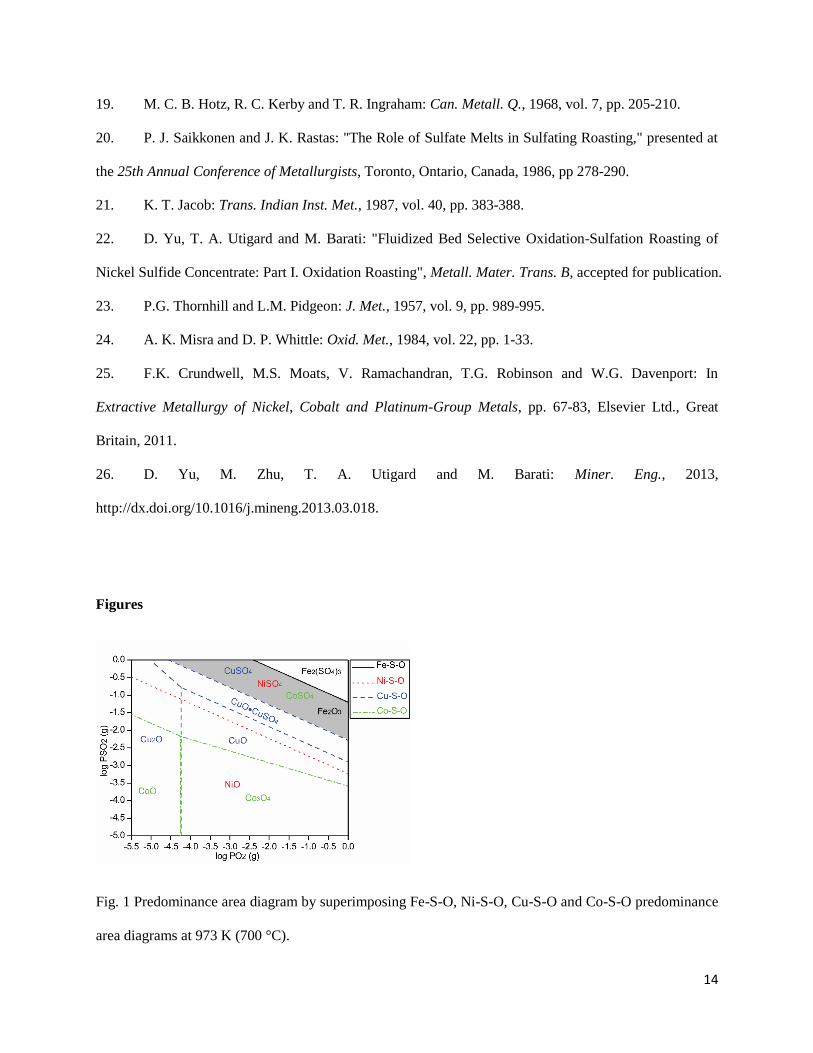
of interests. Fig. 1 depicts the predominance area diagrams in Me-S-O (Me=Fe, Ni, Cu, Co) system at 973 51
K (700 °C) calculated using a thermodynamic software package [3]. The shaded area shows the window 52
of opportunity in which the non-ferrous metal sulfates are stable, while the iron sulfate is not. As a result, 53
the roasting conditions should fall within this window in order to achieve the selective sulfation roast. In 54
practice, the roasting mechanism is rather complicated due to the complexity of the mineralogical 55
composition, the complex heat and mass transfer involved in the multi-phase reactions, and the kinetics of 56
various reactions that may not allow the establishment of equilibrium conditions. Although the fluidized 57
bed roaster has the merit of relatively easy temperature and atmosphere control, the in-situ conditions (i.e. 58
temperature, local gas environment) under which the roasting reactions take place could vary from one 59
position to another or even within individual particles. This may result in the formation of unwanted by-60
products, such as non-ferrous metal oxides. The formation of nickel ferrite (NiFe2O4), a by-product 61
possibly from the solid-solid reaction between iron oxides and nickel oxide due to local overheating in the 62
fluidized bed, is typically detrimental to the sulfation roast. Once formed, nickel ferrite is difficult to 63
sulfatize, which would lead to the nickel loss into the residue during the following leaching step [4-6]. 64
Sulfate formation can take place by two possible reaction routes, which are represented by Reactions (1) 65
to (3). The first is direct sulfation of sulfide while the second involves the sulfation of oxide with sulfur 66
trioxide [7]. It has been generally accepted that the sulfation of nickel sulfides proceeds via the second 67
route, thus requires formation of the oxide [5, 8]. The sulfation of nickel sulfide is an extremely slow 68
process due to the dense nickel sulfate layer formed that inhibits further sulfation [9]. The formation of 69
NiSO4 from NiS requires 2.5 times the space occupied by the original NiS by calculation. This volume 70
increase leads to the dense nature of the NiSO4 [10]. To address the slow-kinetics problem, previous 71
3
studies have investigated the effect of Na2SO4 addition that could accelerate the reactions as described 72
below [5, 11-16]. 73
1). Na2SO4 forms solid solution (β) or binary sulfates (ε,δ,γ) with NiSO4, which can be seen from the 74
NiSO4-Na2SO4 binary phase diagram in Fig. 2 [17]. The formation of any of these phases increases the 75
stability of NiSO4 by lowering its activity, thus preventing the sulfate decomposition [5]. Na2SO4 could 76
also destroy the impervious NiSO4 layer by forming melts possibly below the roasting temperature [18]. 77
As can be seen from Fig. 2, the lowest melting temperature in the NiSO4-Na2SO4 system is the eutectic at 78
approximately 943 K (670 °C), which could be below the normal roasting temperature (923–1023 K 79
(650–750 °C)). 80
2). Na2SO4 destroys the nickel ferrite formed via Reaction (4) [4, 19]. If the Na2SO4 melt contains Fe3+ 81
ions, Reaction (5) will take place; the role of Na2SO4 is to provide the melt conditions for the reactive 82
Fe3+ ions [9, 20-21]. 83
3). Na2SO4 acts as a reservoir of SO3 for the sulfation of NiO via Reactions (6) and (7) [4, 8, 19]. 84
MeS(s) + 2O2(g) = MeSO4(s) (1) 85
SO2(g) + 1/2O2(g) = SO3(g) (2) 86
MeO(s) + SO3(g) = MeSO4(s) (3) 87
NiFe2O4(s) + Na2SO4(s,l) = Na2Fe2O4(s) + NiSO4(s,l) (4) 88
3NiFe2O4(s) + Fe2(SO4)3(melt) = 4Fe2O3(s) + 3NiSO4(melt) (5) 89
Na2SO4(s) + SO3(g) ↔ Na2S2O7(l) (6) 90
SO3(g) + NiO(s) = NiSO4(s) (7) 91
Most of the previous research on sulfation roasting was conducted between 1950 and 1990. The overall 92
technical challenges seem to be the low Ni yield (maximum around 80%) after leaching due largely to the 93
formation of nickel ferrite during roasting, as well as the slow kinetics which made it economically 94
unattractive at that time. Today, however, environmental regulations are more stringent, to the extent that 95
meeting the imposed limits on emissions is forcing the closure of smelters. Energy conservation is more 96
important than ever and emissions of heavy metals are also coming under increasing scrutiny. Therefore, 97
sulfation roasting could be much more attractive from energy, environmental and economic points of 98
view if technical and economic solutions can be found for the above mentioned problems. 99
In this two-part series of papers, a two-stage oxidation-sulfation roasting process for treatment of nickel 100
sulfide concentrate is proposed. The previous article [22] covered the first step, the oxidation roasting 101
with an aim to maximize oxidation of iron while minimizing the formation of nickel ferrite. In this paper, 102
the second stage, the sulfation roasting step, is discussed with the evaluation of several parameters, i.e. the 103
roasting gas flowrate, sulfation roasting temperature, the addition of Na2SO4, the sulfation roasting time, 104
and the oxidation roasting temperature. 105
106

4
2. Materials and methods 107
2.1 Sample 108
Raglan nickel concentrate was received from Xstrata Nickel’s smelter in Sudbury, Ontario, Canada. It 109
was principally composed of pentlandite (Fe,Ni)9S8, chalcopyrite CuFeS2, pyrrhotite Fe1-xS and small 110
amount of siliceous flux and gangue materials. Its chemical composition is shown in Table 1. Sieve 111
analysis on the Raglan concentrate shows 99.4% passing 140 mesh (106 μm), 93.3% passing 200 mesh 112
(74 μm) and 76.7% passing 400 mesh (37 µm). 113
114
2.2 Experimental 115
The same fluidized bed roaster described in the first article [22] was employed. For sulfation roasting 116
experiments, a column of alumina pellets coated with platinum was mounted beneath the porous frit to 117
catalyze the oxidation of SO2 by O2, forming SO3 gas. 118
119
2.3 Analytical methods 120
The products of the sulfation roasting were leached by water at 363 K (90 °C) for 30 minutes to produce 121
leachate and leach residues. The leach residues were fully digested using sodium peroxide (Na2O2) fusion 122
technique. After proper dilution, solutions from both leaching and digestion were analyzed by ICP-OES 123
(PerkinElmer Optima 7200 DV) for the determination of the percentages of the water-soluble species in 124
the calcines after roasting. Details of the sodium peroxide fusion technique and the calculation of the 125
percentages of the water-soluble species are provided in the first article [22] of the series. 126
Calcines were also mounted in the resin, then ground and polished with oil-based diamond suspension for 127
the examination under SEM (JEOL JSM6610-Lv), which was equipped with an EDS detector 128
(Oxford/SSD). 129
130
3. Results and discussion 131
Since the objective of the proposed process was to preferentially oxidize the iron species by oxidation 132
roasting prior to sulfation roasting, sufficient oxidized calcine was prepared as the starting material for the 133
sulfation roasting experiments. Based on the investigation on the oxidation roasting of the nickel 134
concentrate discussed in the first part [22], low temperature (approximately 923 K (650 °C)) is preferable 135
for the preferential oxidation of iron species while minimizing the formation of unwanted nickel ferrite 136
(NiFe2O4). As a result, the Raglan concentrate was first oxidized in the fluidized bed roaster at 923 K 137
(650 °C) with air stream with an apparent gas velocity of 0.17m/s for 10 minutes. SEM/EDS analysis on 138
the calcine particles revealed a sulfide core surrounded by porous hematite rim with small amounts of 139
nickel oxide as inclusion, based on EDS analysis. 140

5
141
3.1 Effect of the Sulfation Roasting Gas Flowrate 142
The effect of the sulfation roasting gas flowrate on the recovery of metal species by water-leaching was 143
firstly examined. The gas composition was fixed at 5% SO2, 19.95% O2 and 75.05% N2, which was 144
achieved by mixing air with SO2 at the ratio of 19:1. The reason for selecting this gas composition was 145
that it falls into the favorable region for selective sulfation in Fig. 1. Furthermore, this gas composition 146
was expected for sulfation roasting in an industrial fluidized bed roaster, because excess air is used 147
industrially for sulfation roasting, thus lower SO2 concentration of the roasting gas is expected than that 148
from the oxidation roasting (approximately 12 vol%). For each test, a mixture of 5 g oxidation roasted 149
calcine and 20 g sand was maintained at 973 K (700 °C) for 30 minutes. Results are plotted in Fig. 3 as 150
percent extraction of elements from the calcines by water, based on the analysis of the products as 151
described earlier. Water-leaching results for the oxidation roasted calcine before sulfation roasting are 152
also plotted at the 0 feed gas flowrate. As can be seen, recovery of non-ferrous metals in the leach 153
solution increased substantially after sulfation roast. The recovery of most of the elements analyzed 154
reached a plateau at the gas flowrates above 1 L/min, which is also the minimum flowrate to achieve 155
fluidization. Therefore, gas flowrate of 1 L/min was applied for further sulfation roasting tests. 156
Recoveries of Co and Cu reached 81 % and 78 %, respectively. Ni recovery is still very low, at around 157
38 %. The dissolution of Fe by water remains constant at 2 %. SEM/EDS analysis was performed on 158
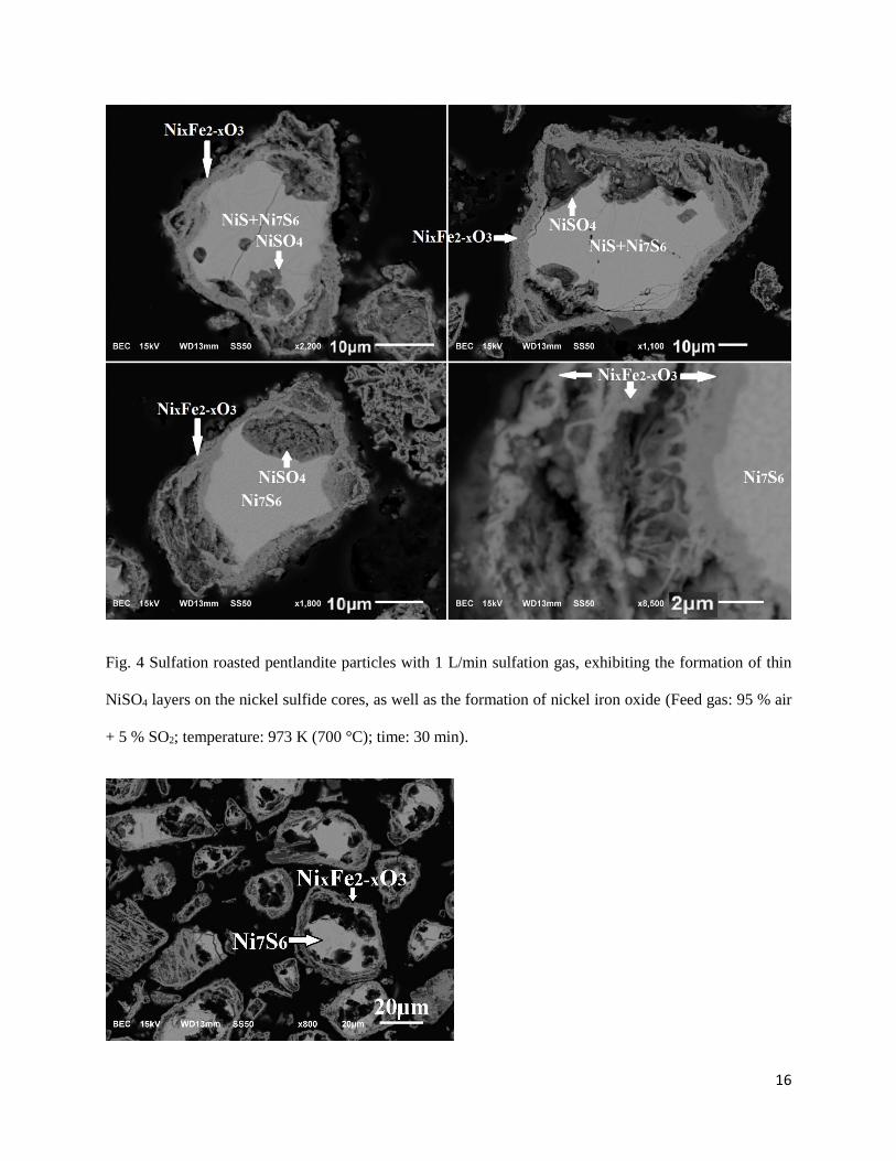
these sulfation roasted calcines. Fig. 4 shows the micrographs of the sulfation roasted pentlandite particles 159
with gas flowrate of 1 L/min. The pores between the sulfide cores and the oxide layers were formed 160
possibly due to the volume reduction during the preferential oxidation of iron species from the pentlandite 161
as well as the formation of SO2. Most of the NiSO4 appears to have formed as a thin layer on the surface 162
of the nickel sulfide cores below the porous oxide layer. The slow kinetics for the NiSO4 formation is 163
probably due to the impervious nature of the NiSO4 formed, which inhibits further sulfation. Sulfate 164
formation is believed to be first promoted by the presence of entrapped gases (SO2 and O2) in the pockets 165
under the oxide layer, and then slowed down as the dense layer becomes thicker. In some particles, a 166
dense iron nickel oxide (NixFe2-xO3) layer, rather than NiSO4, was formed on the sulfide core (e.g. Fig. 4, 167
bottom right corner). This layer of iron nickel oxide, which covered the sulfide core, has most likely been 168
formed during the oxidation roasting stage. By examining the morphologies of the particles presented in 169
Fig. 4, it is apparent that the formation of NiSO4 only occurred on the gas-sulfide interface (bare sulfide 170
surface) in the gas pockets, and no NiSO4 was formed on the gas-oxide interface or oxide-sulfide 171
interface. The gas-sulfide and oxide-sulfide interfaces in the roasted pentlandite particles are formed 172
though different oxidation mechanisms, which are suggested by other researchers [23]. Localized bare 173
sulfide surface would form due to the outward elimination of sulfur by dissociation from the sulfide 174
surface [23]. Gas channels must have formed through the oxide layer(s) to the outer gas environment for 175
the escape of sulfur vapor or SO2 from the shrinkage gap. The formation and growth of the oxide layer on 176
the sulfide surface is due to metal elimination by cations migration through the sulfide to a region of close 177
contact with the oxide layer, through which they further diffuse to the gas-oxide interface [23]. Suitable 178
conditions for NiSO4 formation (Reactions (1-3)) is provided on the bare sulfide surface which has access 179
to the sulfation gas through the gas channels in the oxide layer(s). The formation of sulfate on the sulfide 180
surface is inhibited if there is a firm contact of the relatively dense oxide layer which isolates the sulfation 181
gas. The oxide layer(s) (NixFe2-xO3) formed is thermodynamically stable under the current sulfation 182
roasting conditions, which would not be converted to sulfate. Based on the above discussion, the 183

6
formation of NiSO4 is dependent on the access of the sulfide surface to the sulfation gas, which is further 184
determined by the porosity of the oxide layer(s) and the spatial relation between the sulfide surface and 185
the oxide layer(s). Fig. 5 illustrates the water leaching residue of the sulfation roasted calcine. The sulfate 186
layers were removed after leaching, leaving large gaps between the oxide layer and the nickel sulfide core. 187
188
3.2 Effect of the Sulfation Roasting Temperature 189
The dependence of the percent extraction of various species by water-leaching on the sulfation roasting 190
temperature was investigated. For each test, a mixture of 5 g oxidation roasted calcine and 20 g sand was 191
roasted in 1 L/min of the sulfation gas (5 % SO2, 19.95% O2, and 75.05% N2) at different temperatures, 192
for 30 minutes. The results are shown in Fig. 6. It is evident that the temperature dependency varies for 193
different elements. Recovery of Cu species shows a decreasing trend with the increase of sulfation 194
roasting temperature from 933 K (660 °C) up to 1013 K (740 °C). Co recovery reaches a peak at 973 K 195
(700 °C), while Ni recovery does at 993 K (720 °C). No appreciable dissolution of Fe species is observed 196
in the temperature range of investigation. The effect of the roasting temperature on the recovery of metal 197
species is two-fold. On one hand, temperature increase would enhance the kinetics for the sulfate 198
formation, especially for the formation of NiSO4 which has been shown to be slow. On the other hand, the 199
sulfates are less stable at higher temperatures, indicating that higher temperature favors more oxidation 200
rather than sulfation from a thermodynamic point of view. As a result, the temperature preferable for the 201
sulfation roasting would be the ones high enough to render fast kinetics for the sulfates formation but not 202
excessive as to cause substantial oxidation. High temperature is not preferable for the sulfation of nickel 203
species due to the higher tendency for formation of nickel ferrite. The optimum sulfation roasting 204
temperature based on this series of experiments is 973 K (700 °C), which was adopted for further 205
sulfation roasting experiments. 206
207
3.3 Effect of the Addition of Na2SO4 208
As discussed earlier, Na2SO4 has proven to be an effective promoter for the sulfation roasting [5, 11-16]. 209
Therefore, the addition of Na2SO4 was studied for its effects on the recovery of valuable metals by water-210
leaching. For each experiment, specific amount of Na2SO4 was firstly dissolved in 2.5 g water; then the 211
Na2SO4 solution was blended with 5 g oxidation roasted calcine to make slurry. The slurry was then dried 212
on a hot plate. The agglomerate formed was crushed to pass a 140 mesh sieve. It was then mixed with 20 213
g sand and roasted at 973 K (700 °C) using 1 L/min sulfation gas for 30 minutes. The recoveries were 214
plotted against the weight ratio of Na2SO4 to calcine in Fig. 7. It can be seen that the recovery of Ni was 215
substantially promoted from 38 % to 66 % with the increase of the weight ratio of Na2SO4 to the calcine. 216
Recoveries of Cu and Co were also enhanced by approximately 5 %. There was no increase in the 217
dissolution of Fe species because iron sulfate is not stable at this temperature. The recovery values level 218
off when the addition of Na2SO4 exceeds 10 wt% of calcine. As a result, the optimum Na2SO4 addition for 219
the sulfation roasting under the current experimental conditions would be 10 % of the weight of the 220
calcine. 221

7
The calcines were analyzed with SEM/EDS. Fig. 8 gives the backscattered electron (BSE) images of the 222
sulfation roasted calcines with the weight ratios of Na2SO4 to calcine of 0.02, 0.05 and 0.10. The mixture 223
of the oxidation roasted calcine and 10 % Na2SO4 without sulfation roasting is shown on the top left 224
corner for comparison. Nickel sulfide cores in the images can be distinguished by their brightness. The 225
sulfide cores are monosulfide solid solution (mss, (Ni,Fe)1-xS) with approximately 2 at% Fe before 226
sulfation roasting (top-left image). This phase will further be represented by Ni1-xS for simplification 227
since there is very little Fe in the phase. After sulfation roasting, the sulfide cores are primarily a non-228
stoichiometric sulfur-deficient phase, which can be represented by Ni7S6 on average. This phase also 229
contains approximately 2 at% Fe. By comparison, it is obvious that more nickel sulfide cores were 230
converted to NiSO4 with the addition of higher amounts of Na2SO4. In the bottom right image, which 231
shows the sulfation roasted calcine with 10% Na2SO4 addition, the conversion of nickel sulfide cores to 232
NiSO4 is near completion. Fig. 9 shows a sulfation roasted pentlandite particle with incomplete 233
conversion of the sulfide core to NiSO4 (left) and one with complete conversion to NiSO4 (right). Each 234
NiSO4 core is composed of large amounts of small grains, in which no Na2SO4 was detected. This 235
suggests that the effect of the addition of Na2SO4 on the conversion of nickel sulfide to NiSO4 must be 236
indirect, meaning it takes place without physical contact. One possible mechanism is that the Na2SO4 acts 237
as reservoir of SO3 by forming Na2S2O7, which is a strong sulfating agent, represented by Reaction (6). If 238
the Na2SO4 in the fluidized bed happened to have physical contact with other sulfates, they would 239
preferably form solid solution and/or binary sulfates, resulting in a lowered melting temperature. Such 240
phases could melt in the fluidized bed if their melting point is below the roasting temperature, leading to 241
the agglomeration of particles. For example, Fig. 10 illustrates a cluster of particles agglomerated by a 242
complex mixture of binary sulfates and sulfate solid solutions (Na, Ni, Mg, Cu, Fe). 243
244
3.4 Effect of the Sulfation Roasting Time 245
The effect of the sulfation roasting time on the recoveries of metals was also investigated. Mixtures of 5 g 246
oxidation roasted calcine and 20 g sand with the addition of 10 wt% Na2SO4 were sulfation roasted at 973 247
K (700 °C) for 10 to 360 minutes. The results are shown in Fig. 11. As can be seen, most of the sulfation 248
occurred in the first 10 min with a plateau reached after 150 min. Degrees of sulfation of Co and Cu 249
species are the highest, for 92 % and 89 % respectively, after 150 min roasting. The dissolution of Fe 250
species is constant at around 2 to 3 %. Recovery of Ni reaches 75 %, which is still relatively low. It is of 251
interest to know the type of Ni species that are present in the leach residue. Fig. 12 shows the relative 252
amount of the Ni existing as sulfide and oxide in the water leach residues based on chemical analysis. It 253
indicates that the sulfation of nickel sulfide is faster than the nickel oxide, as the ratio of oxide/sulfide is 254
larger at longer roasting times. After 150 min, the content of Ni existing as oxide in the residue exceeds 255
80 %. This nickel should be associated with iron in the form of nickel ferrite which could have been 256
formed during the oxidation roasting stage. To lower the formation of nickel ferrite, lower oxidation 257
roasting temperatures were attempted with the results presented in the next section. 258
259

8
3.5 Effect of the Oxidation Roasting Temperature 260
In this series of experiments, the temperature of the first stage oxidation roasting was investigated for its 261
effect on the final recoveries of various species by water-leaching after the second stage sulfation roasting 262
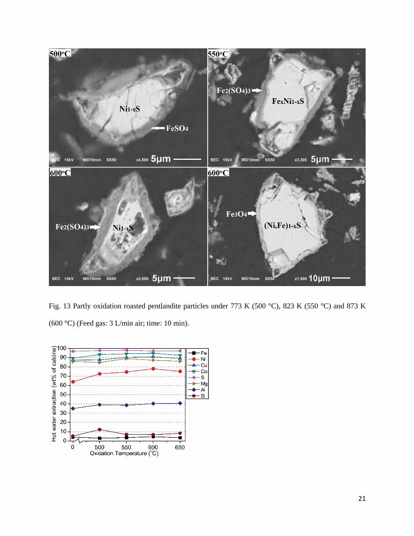
with the addition of Na2SO4. Oxidation roasting tests were performed at 773 K (500 °C), 823 K (550 °C), 263
873 K (600 °C) and 923 K (650 °C) for 10 min with 3 L/min air. Fig. 13 illustrates four partly roasted 264
pentlandite particles treated in different temperatures. At these low temperatures, iron sulfate(s) are stable. 265
A relatively thick (2-3 µm) layer of FeSO4 or Fe2(SO4)3 was formed on the surface of each particle. The 266
sulfide cores are rich in sulfur and some of them even contains substantial amount of iron, indicating a 267
very low degree of oxidation at these temperatures. Because of the excessive amount of sulfur and iron 268
left in the sulfide core, no appreciable nickel ferrite or other nickel iron oxide were formed. Afterwards, 269
these calcines produced under different oxidation roasting temperatures went through sulfation roasting 270
under the following conditions: 10 wt% Na2SO4 addition; roasting time 150 min; temperature 973 K 271
(700 °C); feed gas 5 % SO2, 19.95 % O2, and 75.05 % N2, 1 L/min. In order to investigate the necessity of 272
the first oxidation roasting stage, another test was conducted in which the Raglan concentrate was directly 273
sulfation roasted at 973 K (700 °C) without going through the first oxidation roasting stage, all other 274
conditions remaining identical. The results of these experiments are plotted in Fig. 14. It is clear that it is 275
necessary to have the first oxidation roasting stage since the recovery of Ni is much lower (64 %) without 276
the conduction of the oxidation roasting stage. The Ni curve reaches a peak of 79 % at 873 K (600 °C). 277
The recoveries of Cu and Co are also slightly higher at 873 K (600 °C). Therefore, the optimum oxidation 278
roasting temperature appears to be 873 K (600 °C). 279
The sulfation roasted calcines were examined with SEM/EDS. The results indicate the near-complete 280
conversion of nickel sulfide cores to NiSO4. However, substantial amount of non-stoichiometric nickel 281
ferrite with varying Fe/Ni ratio was found in all samples. Since no appreciable nickel ferrite was formed 282
during the oxidation roasting stage at relatively low temperature, it must have been formed in the 283
sulfation roasting stage along with the formation of sulfates, given a long roasting time (150 min) and 284
relatively high temperature (973 K (700 °C)). Fig. 15 shows the morphologies of the sulfation roasted 285
pentlandite particles. The top-left image shows the calcine produced by direct sulfation of the Raglan 286
concentrate, in which the iron nickel oxide is evenly spread in the nickel sulfate matrix. This 287
morphological feature is much different from that of the other three images, in which the oxide and the 288
sulfate are concentrated in different regions with a defined boundary. This morphological difference is 289
caused by the effect of the first oxidation roasting stage. Most of the iron would be preferentially oxidized 290
to form layer(s) of iron oxides during the oxidation roasting stage, resulting in the physical separation of 291
Fe from Ni through chemical reactions and ion diffusion. On the other hand, one-step direct sulfation 292
roasting of the concentrate results in simultaneous formation of oxide and sulfate, hence their inter-mixed 293
distribution. The side effect is the formation of oxides with a higher amount of Ni. This explains why the 294
Ni recovery is relatively low by direct sulfation roasting as shown in Fig. 14. 295
296
3.6 Mechanism of sulfation 297
It is evident from the above results that the addition of Na2SO4 enhances the sulfation. Other researchers 298
have shown that the enhancement of sulfation results from the destruction of the impervious NiSO4 film 299
by Na2SO4, thus creating new reaction sites for sulfate formation [5]. In the present study, no Na2SO4 was 300

9
present in the sulfate cores of the sulfation roasted pentlandite particles, based on the SEM/EDS analysis. 301
Instead, the sulfate cores were almost pure NiSO4. Na2SO4 was only observed in the sulfate mixture as the 302
outer layer of each particle, which is peripheral to the iron oxide layer that was formed during the 303
oxidation roasting stage, as can be seen in Fig. 15. Since the way the Na2SO4 was mixed with the 304
oxidation roasted calcine was by making slurry, the small amount of sulfates (NiSO4, MgSO4) that was 305
formed during the oxidation roasting stage was probably dissolved into the Na2SO4 solution and formed a 306
sulfates mixture of low melting temperature after drying during the sample preparation. At the initial 307
stage of sulfation roasting, this sulfates mixture would melt and dissolve any NiSO4 that is formed. 308
However, during the progression of the sulfation roasting, it would eventually reach saturation point 309
beyond which the sulfates melt could no longer dissolve more NiSO4 (e.g. once the composition crossed 310
the NiSO4 liquidus line in the NiSO4-Na2SO4 phase diagram, Fig. 2). The formation of NiSO4 beneath the 311
oxide layer of each roasted pentlandite particle requires SO3 as a reactant. SO3 has to first diffuse though 312
the sulfate melt on the surface of each particle via the S2O72--SO4
2- exchange reaction and the counter 313
diffusion of these two ions, then passing through the porous oxide layer. As could be clearly seen from 314
Figs. 9 and 15, the sulfate cores formed within the particles are composed of large amounts of micro 315
grains with cracks and crevices, which provide channels for rapid gas transport. As a result, through these 316
cracks and crevices, the SO3 could reach the surface of the sulfide core where the sulfation reactions 317
would take place. 318
Fig. 16 shows the BSE image of another partly roasted pentlandite particle with a nickel sulfide core. This 319
sulfide core is composed of two phases, which can be seen as areas with two grey levels after contrast 320
enhancement shown in the top-right corner. The darker inner core is sulfur-rich and nickel-deficient 321
monosulfide solid solution (Ni1-xS with 2 at% Fe), while the brighter outer phase is Ni7S6. This indicates 322
that the conversion of the sulfide core from Ni1-xS to Ni7S6 accompanies the NiSO4 formation, which 323
could be represented by Reaction (8). In the first paper of this series [22], it has been shown that the 324
sulfide cores of the partly roasted pentlandite particles in the calcines are more sulfur-deficient at higher 325
roasting temperatures. Therefore, the driving force for Reaction (8) is likely the higher sulfation roasting 326
temperature (973 K (700 °C)) compared with the oxidation roasting temperature (923 K (650 °C)). Sulfur 327
elimination from sulfide as represented by Reaction (8) is achieved by first migration of sulfur ions from 328
interior of the sulfide to the surface [23] where it could combine with O2. During the conversion of the 329
sulfide cores to Ni7S6, the sulfation reaction would proceed according to Reaction (9). The SO2 required 330
for the sulfation reaction could be provided from Reaction (8). Furthermore, Reaction (8) would also 331
result in the shrinkage of the sulfide core, which provides more space for the formation of NiSO4 on the 332
sulfide surface beneath the oxide layers. Evidence for this could be found in Fig. 16, in which the large 333
shrinkage gaps between the sulfide core and the oxide layers are filled with NiSO4. The oxygen required 334
for the oxidation and sulfation reactions (Reactions (8–9)) could be supplied by either the decomposition 335
of SO3 or the inward diffusion of O2 from the gas. The overall sulfation mechanism by diffusion could be 336
schematically represented by Fig. 17. 337
7Ni1-xS(s) + (1+6x)O2(g) = (1-x)Ni7S6(s) + (1+6x)SO2(g) (8) 338
Ni7S6(s) + SO2(g) + 13O2(g) = 7NiSO4(s) (9) 339
As represented by Reaction (9), the sulfation reaction does not involve metal oxide(s) as intermediate 340
product(s). This is consistent with the SEM observations in the present study. This differs from the 341

10
mechanism proposed by earlier researchers [5, 8]. In order to further investigate this, another series of 342
tests was performed. Two samples of nickel sulfide (main phases: NiS, Ni3S2) were ground and polished 343
to make flat surfaces. Appropriate amount of Na2SO4 solution was then sprayed onto the surface of one 344
sulfide sample and dried to have a layer of Na2SO4 deposited on the sulfide with an average thickness of 345
10-20 μm. For comparison, the other sulfide sample was not coated with Na2SO4. Both of these 346
specimens were suspended with the flat surfaces facing downwards in the roaster at 973 K (700 °C). 347
Sulfation gas (5 % SO2, 95 % air) of 3 L/min was introduced to the flat surfaces. Both of these two sulfide 348
samples were pulled out from the roaster after 30 min. They were then cut and prepared for observation 349
under SEM/EDS. Their morphologies are shown in Fig. 18. As can be seen, without the Na2SO4 coating, 350
NiO was formed on the surface and propagated into the sample for hundreds of micrometers. Those black 351
areas in the sulfide sample are crevices believed to have formed due to the volume reduction during the 352
oxidation of nickel sulfide. No NiSO4 was formed in the sample under the current sulfation roasting 353
conditions. For comparison, NiSO4 was formed on the surface of the sulfide cores beneath the oxide layer 354
as shown in Fig. 4 during the sulfation roasting with the same sulfation gas composition and temperature. 355
This indicates that the presence of the porous oxide layer maintains a stronger sulfation gas environment, 356
i.e. higher partial pressure of SO3, beneath the oxide layer. And the presence of the Na2SO4-NiSO4 357
sulfates melt as an outer layer as shown in Figs. 8 and 9 further enhanced this effect. The other three 358
images in Fig. 18 illustrate the direct interaction between Na2SO4 and the sulfide sample under sulfation 359
conditions. In the top-right and bottom-left images, only a layer of sulfate(s) with varying Na/Ni ratio was 360
formed on the sulfide sample. There is a layer of Ni2O3 in between the sulfide core and the sulfates layer 361
in the bottom-right image. The formation of Ni2O3 with a valence state of Ni3+ could not possibly result 362
from the oxidation of nickel sulfides, as it is thermodynamically unstable under the present experimental 363
conditions. The oxidation product would be NiO rather than Ni2O3, if any. Misra and Whittle [24] studied 364
the effects of SO2 and SO3 on the Na2SO4 induced hot corrosion of nickel. They also found the formation 365
of a layer of Ni2O3 beneath the porous NiO scale in the presence of Na2SO4 at 1023 K (750 °C). They 366
proved the formation of the metastable Ni2O3 was from the decomposition of the NiSO4 component of the 367
Na2SO4-NiSO4 melt, which was then slowly converted to NiO. As a result, it is believed that in the 368
present study as shown in the bottom-right corner of Fig. 18, the layer of Ni2O3 was also from the 369
decomposition of the NiSO4 component of the outermost layer of Na2SO4-NiSO4 melt. It is therefore 370
evident that the sulfation of NiS does not involve the preliminary formation of NiO as intermediate 371
compound. The NiS could be directly converted to NiSO4 by the sulfation gas given a favorable sulfation 372
conditions. The role of the Na2SO4 in the sulfation is to quickly dissolve the NiSO4 formed to form a 373
sulfate melt and expose new sites on the sulfide for sulfation. Also it accelerates the transportation of the 374
sulfation gas (SO3) to the sulfide with the S2O72--SO4
2- equilibrium in the sulfate melt. 375
One important observation of the present study is the formation of micro grains of NiSO4 with cracks and 376
crevices in the pentlandite particles which facilitate the formation of NiSO4 by providing channels for the 377
access of the sulfation gas. It is suggested these cracks and crevices have formed due to the combination 378
of several factors: 1) The high temperature (973 K (700 °C)) results in high kinetics for reactions; 2) The 379
double sulfates melt-porous oxide layers surrounding the sulfide core maintain a very favorable gas 380
environment for sulfate formation; 3) The volume increases by approximately 150 % as nickel sulfide 381
(NiS) is converted to sulfate, which introduces significant stresses into the sulfate formed; 4) Due to the 382
easy access of sulfation gas to the sulfide surface through the already-formed cracks and crevices, more 383
NiSO4 forms at a relatively quick rate so that more stress is added to the sulfate particle before the stress 384

11
in the particle is relieved by atomic rearrangement; 5) With the continuous mounting of the stress, a 385
critical point is reached so that a new crack is formed and developed, providing more channels for the 386
migration of sulfation gas to the surface of the sulfide. As a result, the sulfation is self-sustained by the 387
development of cracks and crevices. 388
389
3.7 Leach residue 390
Under optimum roasting conditions as suggested by the present study, 79 % Ni, 91 % Cu and 95 % Co 391
could be recovered by leaching with water after sulfation roasting. Fe can be effectively rejected by 392
forming iron oxides. And the soluble Fe is only 4 % during leaching. The Ni recovery is still relatively 393
low due to the formation of nickel ferrite during the sulfation roasting stage, which ends up in the leach 394
residue. Leach residue from the optimized two-stage sulfation roasting test is mainly composed of 395
hematite (Fe2O3) and nickel ferrite (NiFe2O4) analyzing 49 % Fe, 10 % Ni, 1 % Cu, 1 % S, and 5 % Si. In 396
the smelting of nickel laterite ores to ferronickel, the dried and partially reduced calcine for smelting in 397
the electric furnace contains 1.5−3 % Ni and 15 % Fe [25]. By comparison, the leach residue could be a 398
superior feedstock for the production of ferronickel, because the concentrations of the valuable metals (Ni 399
and Fe) in the leach residue are more than three-fold, meaning the energy consumption per tonne of 400
ferronickel produced would be reduced tremendously. In addition, the ratio of Ni/Fe is higher in the leach 401
residue, indicating higher value of this material. Production of ferronickel from this leach residue by H2 402
reduction has been investigated [26], suggesting its feasibility. 403
404
4. Conclusions 405
A two-stage selective oxidation-sulfation roasting was investigated as an alternative process for nickel 406
production from nickel sulfide concentrate using a batch fluidized bed roaster. Several parameters were 407
studied, i.e. the sulfation gas flowrate, sulfation roasting temperature, the addition of Na2SO4, sulfation 408
roasting time, and the oxidation roasting temperature. The following conclusions were drawn. 409
(1) Under optimized conditions of sulfation gas composition (95 % air, 5 % SO2), temperature (973 K 410
(700 °C)), Na2SO4 addition (10 wt%) and time (150 min), the recoveries of valuable metals are 79 % Ni, 411
91 % Cu, and 95 % Co. Only 4 % Fe forms water-soluble sulfate. 412
(2)The residue from the leaching of calcine in water contains 49 % Fe and 10 % Ni. 413
(3) The Na2SO4 formed sulfates melt with other sulfates on the surface of particles during sulfation 414
roasting which is believed to have helped maintaining a high partial pressure of SO3 within each particle 415
favoring sulfate formation. 416
(4) Conversion of sulfide cores from Ni1-xS to Ni7S6, which resulted from the outer diffusion of sulfur ions, 417
accompanied the NiSO4 formation. Shrinkage gaps formed from this conversion provided more space for 418
further formation of NiSO4. 419
(5) The direct sulfation of the nickel sulfide occurs without the preliminary formation of NiO as 420
intermediate product. 421
12
(6) The NiSO4 formed were micro grains with cracks and crevices which allowed the sulfation to proceed 422
to near completion by providing channels for the inner diffusion of sulfation gas to the sulfide surface. 423
424
Acknowledgements 425
The authors wish to thank Xstrata Process Support (Sudbury, Ontario, Canada) for providing the 426
concentrate and both Xstrata and Vale for sponsoring the project. We acknowledge the constructive 427
comments received from Dr. Gus Van Weert of the ORETOME Ltd. The funding for this research was 428
provided by the Natural Sciences and Engineering Research Council (NSERC) of Canada. 429

13
References
1. R. Schonewille, M. Boissoneault, D. Ducharme and J. Chenier: "Update on Falconbridge's
Sudbury nickel smelter," presented at the Nickel and Cobalt 2005, 44th Annual Conference of
Metallurgists, Calgary, Canada, 2005, pp. 479-498.
2. Report: "Moving towards Sustainability, 2005 Good Neighbours Report on Helth, Safety,
Environment and Community", Inco Limited, Toronto, Canada, 2005.
3. A. Roine: HSC Chemistry, version 6.12 for Windows, Outokumpu Research Oy, Pori, Finland,
2007.
4. P. G. Thornhill: U.S. Patent 2 813 016, November 12, 1957.
5. A. W. Fletcher and M. Shelef: Unit Process in Hydrometallurgy. Group C: Plant Operating
Practice - Economics - General, pp. 946-970, New York Gordon and Breach Science Publishers, New
York, 1965.
6. A. W. Fletcher and M. Shelef: Trans. TMS-AIME, 1964, vol. 230, pp. 1721-1724.
7. J. G. Dunn: Thermochim. Acta, 1997, vol. 300, pp. 127-139.
8. M. C. B. Hotz and T. R. Ingraham: Can. Metall. Q., 1966, vol. 5, pp. 237-244.
9. P. J. Saikkonen: U.S. Patent 4 464 344, August 7, 1984.
10. M. C. B. Hotz and T. R. Ingraham: Can. Metall. Q., 1965, vol. 4, pp. 295-302.
11. W. K. Sproule, P. E. Queneau and G. C. Nowlan Jr: Canada Patent CA 593622, March 1, 1960.
12. P. G. Thornhill: U.S. Patent 2 930 604, March 29, 1960.
13. K. L. Luthra: Metall. Trans. A, 1982, vol. 13A, pp. 1647-1654.
14. N. Zubryckyj, D. J. I. Evans and V. N. Mackiw: J. Met., 1965, vol. 17, pp. 478-486.
15. P. G. Thornhill: AIME Trans., 1961, vol. LXIV, pp. 337-344.
16. Joseph R. Boldt, Jr.: The Winning of Nickel, pp. 331-336, Longmans Canada, Toronto, 1967.
17. N. Birks, G. H. Meier and F. S. Pettit: Introduction to The High-Temperature Oxidation of Metals,
pp. 205-252, Cambridge University Press, United States of America, 2006.
18. J. M. Toguri: Can. Metall. Q., 1975, vol. 14, pp. 323-338.
14
19. M. C. B. Hotz, R. C. Kerby and T. R. Ingraham: Can. Metall. Q., 1968, vol. 7, pp. 205-210.
20. P. J. Saikkonen and J. K. Rastas: "The Role of Sulfate Melts in Sulfating Roasting," presented at
the 25th Annual Conference of Metallurgists, Toronto, Ontario, Canada, 1986, pp 278-290.
21. K. T. Jacob: Trans. Indian Inst. Met., 1987, vol. 40, pp. 383-388.
22. D. Yu, T. A. Utigard and M. Barati: "Fluidized Bed Selective Oxidation-Sulfation Roasting of
Nickel Sulfide Concentrate: Part I. Oxidation Roasting", Metall. Mater. Trans. B, accepted for publication.
23. P.G. Thornhill and L.M. Pidgeon: J. Met., 1957, vol. 9, pp. 989-995.
24. A. K. Misra and D. P. Whittle: Oxid. Met., 1984, vol. 22, pp. 1-33.
25. F.K. Crundwell, M.S. Moats, V. Ramachandran, T.G. Robinson and W.G. Davenport: In
Extractive Metallurgy of Nickel, Cobalt and Platinum-Group Metals, pp. 67-83, Elsevier Ltd., Great
Britain, 2011.
26. D. Yu, M. Zhu, T. A. Utigard and M. Barati: Miner. Eng., 2013,
http://dx.doi.org/10.1016/j.mineng.2013.03.018.
Figures
Fig. 1 Predominance area diagram by superimposing Fe-S-O, Ni-S-O, Cu-S-O and Co-S-O predominance
area diagrams at 973 K (700 °C).

15
Fig. 2 NiSO4-Na2SO4 phase diagram [17].
Fig. 3 Effect of the sulfation roasting gas flowrate on the formation of water-soluble species (Feed gas:
95 % air + 5 % SO2; temperature: 973 K (700 °C); time: 30 min).
16
Fig. 4 Sulfation roasted pentlandite particles with 1 L/min sulfation gas, exhibiting the formation of thin
NiSO4 layers on the nickel sulfide cores, as well as the formation of nickel iron oxide (Feed gas: 95 % air
+ 5 % SO2; temperature: 973 K (700 °C); time: 30 min).

17
Fig. 5 Leach residue of the sulfation roasted calcine with sulfation gas flowrate of 1 L/min (Feed gas: 95 %
air + 5 % SO2; temperature: 973 K (700 °C); time: 30 min).
Fig. 6 Effect of the sulfation roasting temperature on the formation of water-soluble species (Feed gas: 1
L/min, 95 % air + 5 % SO2; time: 30 min).
Fig. 7 Effect of the addition of Na2SO4 on the formation of water-soluble species (Feed gas: 1 L/min, 95 %
air + 5 % SO2; temperature: 973 K (700 °C); time: 30 min).

18
Fig. 8 SEM images of the oxidation roasted calcine blended with 10 wt% Na2SO4 (top-left), and sulfation
roasted calcines with the addition of Na2SO4 of 2 % (top-right), 5 % (bottom-left), and 10 % (bottom-right)
with regard to the weight of the calcine (mss: monosulfide solid solution, (Ni,Fe)1-xS), (Feed gas: 1 L/min,
95 % air + 5 % SO2; temperature: 973 K (700 °C); time: 30 min).
Fig. 9 Incomplete (left) and complete (right) conversion of nickel sulfide cores to NiSO4 with the addition
of Na2SO4 (Feed gas: 1 L/min, 95 % air + 5 % SO2; temperature: 973 K (700 °C); time: 30 min).

19
Fig. 10 Cluster of calcine particles agglomerated by sulfates mixtures with 5% Na2SO4 addition (Feed gas:
1 L/min, 95% air + 5% SO2; temperature: 973 K (700 °C); time: 30 min).
Fig. 11 Effect of the sulfation roasting time on the formation of water-soluble species (Feed gas: 1 L/min,
95 % air + 5 % SO2; temperature: 973 K (700 °C); Na2SO4 addition: 10 wt% of calcine).

20
Fig. 12 Relative amount of Ni existing as sulfide and oxide (%) in the leach residue against sulfation
roasting time (Feed gas: 1 L/min, 95 % air + 5 % SO2; temperature: 973 K (700 °C); Na2SO4 addition: 10
wt% of calcine).
21
Fig. 13 Partly oxidation roasted pentlandite particles under 773 K (500 °C), 823 K (550 °C) and 873 K
(600 °C) (Feed gas: 3 L/min air; time: 10 min).

22
Fig. 14 Effect of the temperature of the oxidation roasting stage on the formation of water-soluble species
in the sulfation roasting stage at 973 K (700 °C) (Feed gas: 3 L/min air; time: 10 min).
Fig. 15 Sulfation roasted pentlandite particles: single stage sulfation roasting at 973 K (700 °C) (top-left);
two-stage roasting with the oxidation roasting temperature of 773 K (500 °C) (top-right), 823 K (550 °C)
(bottom-left) and 873 K (600 °C) (bottom-right) (Feed gas for oxidation: 3 L/min air; time: 10 min; feed
gas for sulfation: 1 L/min, 95 % air + 5 % SO2; temperature: 973K (700 °C); Na2SO4 addition: 10 wt% of
calcine).

23
Fig. 16 Sulfation roasted pentlandite particle with 20 wt% addition of Na2SO4 at 973 K (700 °C) for 30
min. The sulfide core was isolated and shown in the top-right corner with enhanced contrast illustrating
the presence of two sulfide phases (Feed gas: 1 L/min, 95 % air + 5 % SO2).
Fig. 17 Schematic representation of the sulfation mechanism.

24
Fig. 18 Nickel sulfide samples uncoated (top-left) and coated with Na2SO4 (the rest three), sulfation
roasted at 973 K (700 °C) for 30 min (Feed gas: 3 L/min, 95 % air + 5 % SO2).
Table
Table 1 – Chemical composition of the Raglan concentrate.
Constituents Ni Fe Cu Co S MgO Al2O3 SiO2 Total
Weight % 17.9 30.8 4.54 0.36 27.6 5.43 0.76 8.69 96.1