Embed Size (px)
Citation preview
EN 7
.654
.3/0
6.18
229
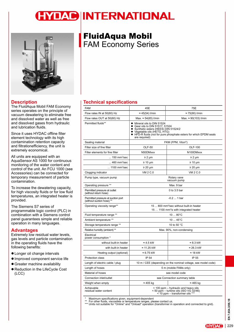
FluidAqua Mobil FAM Economy Series
DescriptionThe FluidAqua Mobil FAM Economy series operates on the principle of vacuum dewatering to eliminate free and dissolved water as well as free and dissolved gases from hydraulic and lubrication fluids.
Since it uses HYDAC offline filter element technology with its high contamination retention capacity and filtrationefficiency, the unit is extremely economical.
All units are equipped with an AquaSensor AS 1000 for continuous monitoring of the water content and control of the unit. An FCU 1000 (see Accessories) can be connected for temporary measurement of particle contamination.
To increase the dewatering capacity, for high viscosity fluids or for low fluid temperatures, an integrated heater is provided.
The Siemens S7 series of programmable logic control (PLC) in combination with a Siemens control panel guarantees simple and reliable operation in many languages.
AdvantagesExtremely low residual water levels, gas levels and particle contamination in the operating fluids have the following benefits:
zLonger oil change intervals z Improved component service life zGreater machine availability zReduction in the LifeCycle Cost (LCC)
Technical specificationsFAM 45E 75E
Flow rates IN at 50(60) Hz ≈ 45(54) l/min ≈ 75(90) l/min
Flow rates OUT at 50(60) Hz Max. ≈ 54(65) l/min Max. ≈ 90(103) l/min
Permitted fluids** z Mineral oils to DIN 51524 z Gear oils to DIN 51517, 51524 z Synthetic esters (HEES) DIN 51524/2 z Vegetable oils (HETG, HTG) z HFD-R fluids (not for pure phosphate esters for which EPDM seals are required)
Sealing material FKM (FPM, Viton®)
Filter size of fine filter OLF-50 OLF-100
Filter elements for fine filter N50DMxxx N100DMxxx
... 150 mm2/sec ≥ 2 µm ≥ 2 µm
... 460 mm2/sec ≥ 10 µm ≥ 10 µm
... 1100 mm2/sec ≥ 20 µm ≥ 20 µm
Clogging indicator VM 2 C.0 VM 2 C.0
Pump type, vacuum pump Rotary vane vacuum pump
Operating pressure ** Max. 9 bar
Permitted pressure at outlet (without return hose)
0 to 3.5 bar
Permitted pressure at suction port (without suction hose) **
-0.2 ... 1 bar
Operating viscosity range** 15 ... 800 mm²/sec without built-in heater15 … 1100 mm2/s with integrated heater
Fluid temperature range ** 10 ... 80°C
Ambient temperature ** 10 ... 45°C
Storage temperature range ** 10 to 50 °C
Relative humidity (ambient) ** Max. 90%, non-condensing
Electrical power consumption *
without built-in heater ≈ 4.5 kW ≈ 8.3 kW
with built-in heater ≈ 11.25 kW ≈ 26.3 kW
Heating output (optional) ≈ 6.75 kW ≈ 18 kW
Protection class IP 54 IP 55
Length of electric cable / plug 10 m / CEE (depending on the nominal voltage, see model code)
Length of hoses 5 m (mobile FAMs only)
Material of hoses see model code
Connection inlet/outlet see Connection summary table
Weight when empty ≈ 405 kg ≈ 465 kg
Achievable residual water content
< 100 ppm – hydraulic and heavy oils < 50 ppm – turbine oils (ISO VG 32/46)
< 10 ppm – transformer oils ***
* Maximum specifications given, equipment-dependent ** For other fluids, viscosities or temperature ranges, please contact us. *** Units not suitable for "Online" and "Onload" operation (transformer in operation and connected to grid).
EN 7
.654
.3/0
6.18
230
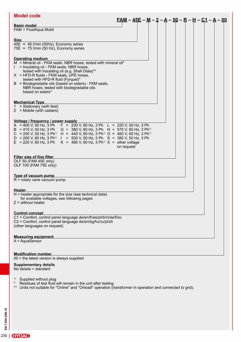
Model code FAM – 45E – M – 2 – A – 50 – R – H – C1 – A – 00Basic model FAM = FluidAqua Mobil
Size 45E ≈ 45 l/min (50Hz), Economy series 75E ≈ 75 l/min (50 Hz), Economy series
Operating medium M = Mineral oil - FKM seals, NBR hoses, tested with mineral oil* I = Insulating oil - FKM seals, NBR hoses, tested with insulating oil (e.g. Shell Diala)** X = HFD-R fluids - FKM seals, UPE hoses, tested with HFD-R fluid (Fyrquel)* B = Biodegradable oils (based on esters) - FKM seals, NBR hoses, tested with biodegradable oils based on esters*
Mechanical Type 1 = Stationary (with feet) 2 = Mobile (with casters)
Voltage / frequency / power supply A = 400 V, 50 Hz, 3 Ph F = 230 V, 60 Hz, 3 Ph L = 220 V, 50 Hz, 3 Ph B = 415 V, 50 Hz, 3 Ph G = 380 V, 60 Hz, 3 Ph N = 575 V, 60 Hz, 3 Ph1) C = 200 V, 50 Hz, 3 Ph1) H = 440 V, 60 Hz, 3 Ph1) O = 460 V, 60 Hz, 3 Ph1) D = 200 V, 60 Hz, 3 Ph1) I = 500 V, 50 Hz, 3 Ph S = 380 V, 50 Hz, 3 Ph E = 220 V, 60 Hz, 3 Ph K = 480 V, 60 Hz, 3 Ph1) X = other voltage on request
Filter size of fine filter OLF 50 (FAM 45E only) OLF 100 (FAM 75E only)
Type of vacuum pump R = rotary vane vacuum pump
Heater H = heater appropriate for the size (see technical data) for available voltages, see following pages Z = without heater
Control concept C1 = Comfort, control panel language de/en/fr/es/pt/it/nl/da/fi/sv C2 = Comfort, control panel language de/en/bg/hu/ru/pl/zh (other languages on request)
Measuring equipment A = AquaSensor
Modification number 00 = the latest version is always supplied
Supplementary details No details = standard
1) Supplied without plug * Residues of test fluid will remain in the unit after testing. ** Units not suitable for "Online" and "Onload" operation (transformer in operation and connected to grid).
EN 7
.654
.3/0
6.18
231
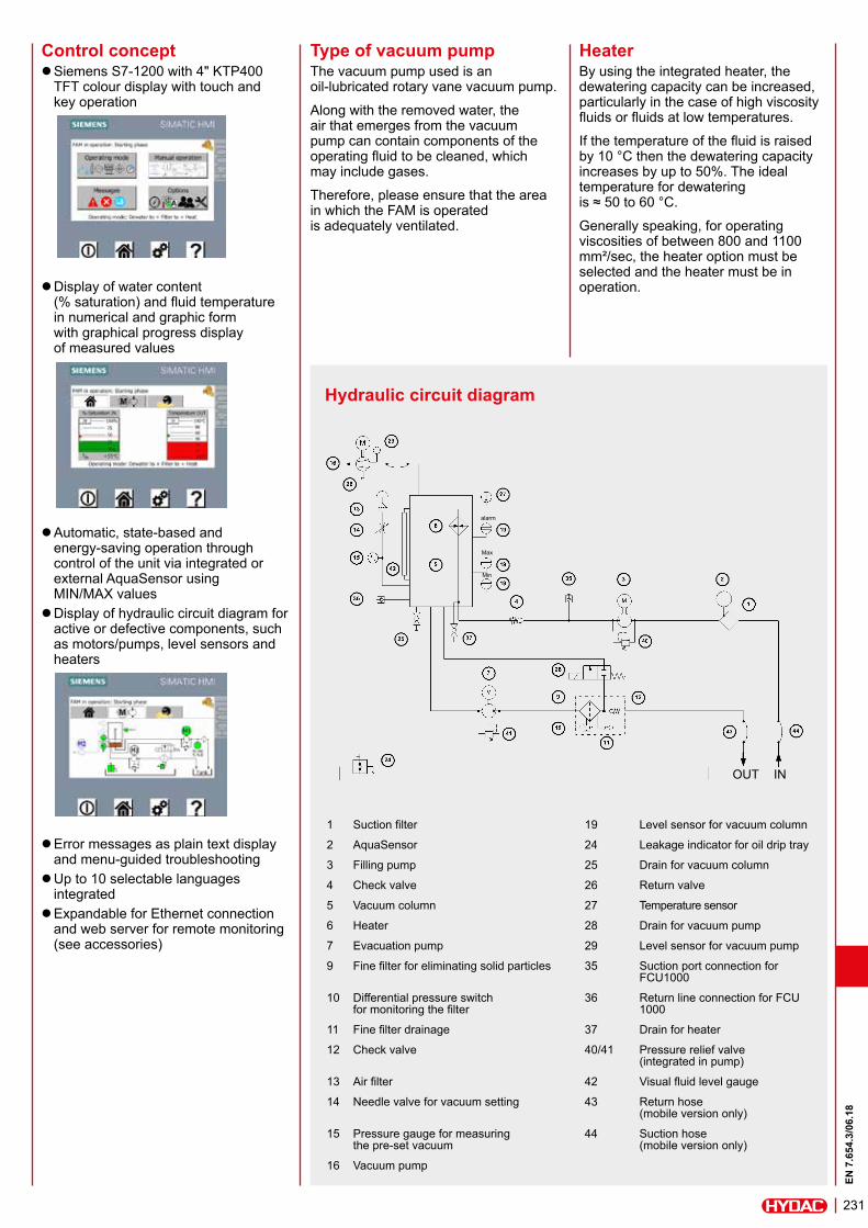
Hydraulic circuit diagram
Control concept zSiemens S7-1200 with 4" KTP400 TFT colour display with touch and key operation
zDisplay of water content (% saturation) and fluid temperature in numerical and graphic form with graphical progress display of measured values
zAutomatic, state-based and energy-saving operation through control of the unit via integrated or external AquaSensor using MIN/MAX values zDisplay of hydraulic circuit diagram for active or defective components, such as motors/pumps, level sensors and heaters
zError messages as plain text display and menu-guided troubleshooting zUp to 10 selectable languages integrated zExpandable for Ethernet connection and web server for remote monitoring (see accessories)
Type of vacuum pumpThe vacuum pump used is an oil-lubricated rotary vane vacuum pump.
Along with the removed water, the air that emerges from the vacuum pump can contain components of the operating fluid to be cleaned, which may include gases.
Therefore, please ensure that the area in which the FAM is operated is adequately ventilated.
HeaterBy using the integrated heater, the dewatering capacity can be increased, particularly in the case of high viscosity fluids or fluids at low temperatures.
If the temperature of the fluid is raised by 10 °C then the dewatering capacity increases by up to 50%. The ideal temperature for dewatering is ≈ 50 to 60 °C.
Generally speaking, for operating viscosities of between 800 and 1100 mm²/sec, the heater option must be selected and the heater must be in operation.
1 Suction filter 19 Level sensor for vacuum column
2 AquaSensor 24 Leakage indicator for oil drip tray
3 Filling pump 25 Drain for vacuum column
4 Check valve 26 Return valve
5 Vacuum column 27 Temperature sensor
6 Heater 28 Drain for vacuum pump
7 Evacuation pump 29 Level sensor for vacuum pump
9 Fine filter for eliminating solid particles 35 Suction port connection for FCU1000
10 Differential pressure switch for monitoring the filter
36 Return line connection for FCU 1000
11 Fine filter drainage 37 Drain for heater
12 Check valve 40/41 Pressure relief valve (integrated in pump)
13 Air filter 42 Visual fluid level gauge
14 Needle valve for vacuum setting 43 Return hose (mobile version only)
15 Pressure gauge for measuring the pre-set vacuum
44 Suction hose (mobile version only)
16 Vacuum pump
alarm
Max
Min
OUT IN
EN 7
.654
.3/0
6.18
232
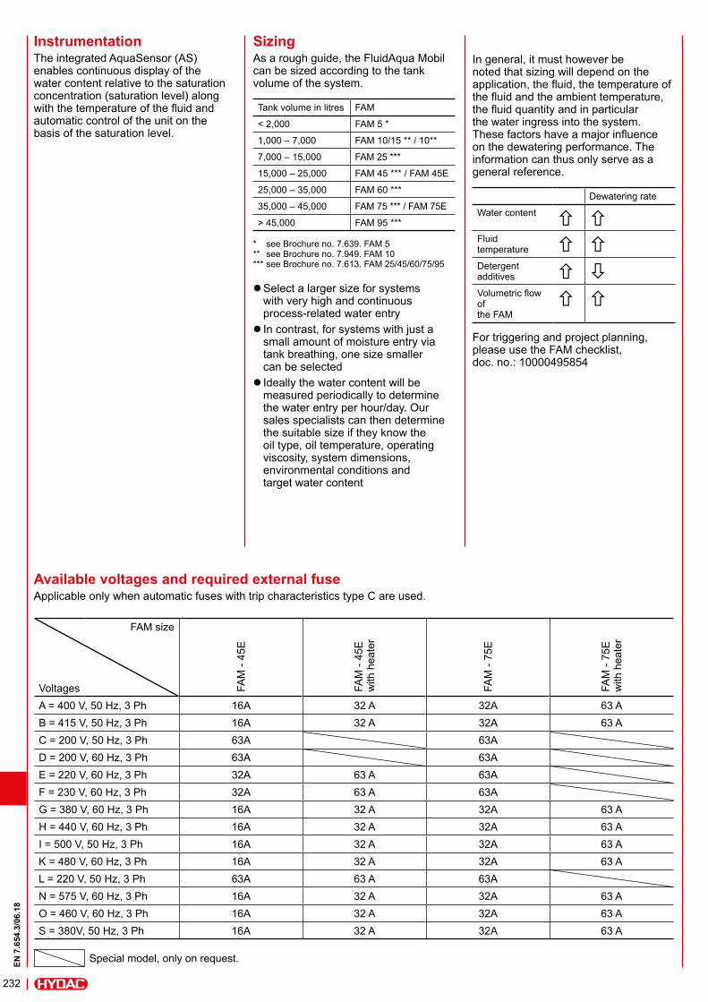
Available voltages and required external fuseApplicable only when automatic fuses with trip characteristics type C are used.
FAM size
Voltages FAM
- 45
E
FAM
- 45
E
with
hea
ter
FAM
- 75
E
FAM
- 75
E
with
hea
ter
A = 400 V, 50 Hz, 3 Ph 16A 32 A 32A 63 AB = 415 V, 50 Hz, 3 Ph 16A 32 A 32A 63 AC = 200 V, 50 Hz, 3 Ph 63A 63AD = 200 V, 60 Hz, 3 Ph 63A 63AE = 220 V, 60 Hz, 3 Ph 32A 63 A 63AF = 230 V, 60 Hz, 3 Ph 32A 63 A 63AG = 380 V, 60 Hz, 3 Ph 16A 32 A 32A 63 AH = 440 V, 60 Hz, 3 Ph 16A 32 A 32A 63 AI = 500 V, 50 Hz, 3 Ph 16A 32 A 32A 63 AK = 480 V, 60 Hz, 3 Ph 16A 32 A 32A 63 AL = 220 V, 50 Hz, 3 Ph 63A 63 A 63AN = 575 V, 60 Hz, 3 Ph 16A 32 A 32A 63 AO = 460 V, 60 Hz, 3 Ph 16A 32 A 32A 63 AS = 380V, 50 Hz, 3 Ph 16A 32 A 32A 63 A
Special model, only on request.
InstrumentationThe integrated AquaSensor (AS) enables continuous display of the water content relative to the saturation concentration (saturation level) along with the temperature of the fluid and automatic control of the unit on the basis of the saturation level.
SizingAs a rough guide, the FluidAqua Mobil can be sized according to the tank volume of the system.
Tank volume in litres FAM
< 2,000 FAM 5 *
1,000 – 7,000 FAM 10/15 ** / 10**
7,000 – 15,000 FAM 25 ***
15,000 – 25,000 FAM 45 *** / FAM 45E
25,000 – 35,000 FAM 60 ***
35,000 – 45,000 FAM 75 *** / FAM 75E
> 45,000 FAM 95 ***
* see Brochure no. 7.639. FAM 5** see Brochure no. 7.949. FAM 10*** see Brochure no. 7.613. FAM 25/45/60/75/95
zSelect a larger size for systems with very high and continuous process-related water entry z In contrast, for systems with just a small amount of moisture entry via tank breathing, one size smaller can be selected z Ideally the water content will be measured periodically to determine the water entry per hour/day. Our sales specialists can then determine the suitable size if they know the oil type, oil temperature, operating viscosity, system dimensions, environmental conditions and target water content
In general, it must however be noted that sizing will depend on the application, the fluid, the temperature of the fluid and the ambient temperature, the fluid quantity and in particular the water ingress into the system. These factors have a major influence on the dewatering performance. The information can thus only serve as a general reference.
Dewatering rate
Water content Fluid temperature Detergent additives Volumetric flow of the FAM
For triggering and project planning, please use the FAM checklist, doc. no.: 10000495854
EN 7
.654
.3/0
6.18
233
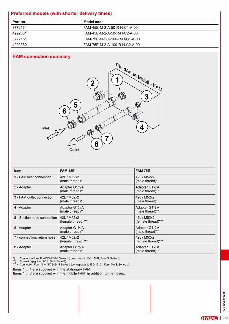
FAM connection summary
*) Connection Form D to ISO 8434-1 Series L (corresponds to ISO 12151, Form S, Series L) **) Screw-in spigot to ISO 1179-2 (Form E) *** ) Connection Form N to ISO 8434-4 Series L (corresponds to ISO 12151, Form SWS, Series L)
Items 1 ... 4 are supplied with the stationary FAM. Items 1 ... 8 are supplied with the mobile FAM, in addition to the hoses.
Item FAM 45E FAM 75E
1 - FAM inlet connection 42L / M52x2 (male thread)*
42L / M52x2 (male thread)*
2 - Adapter Adapter G1½ A (male thread)**
Adapter G1½ A (male thread)**
3 - FAM outlet connection 42L / M52x2 (male thread)*
42L / M52x2 (male thread)*
4 - Adapter Adapter G1½ A (male thread)**
Adapter G1½ A (male thread)**
5 - Suction hose connection 42L / M52x2 (female thread)***
42L / M52x2 (female thread)***
6 - Adapter Adapter G1½ A (male thread)**
Adapter G1½ A (male thread)**
7 - connection, return hose 42L / M52x2 (female thread)***
42L / M52x2 (female thread)***
8 - Adapter Adapter G1½ A (male thread)**
Adapter G1½ A (male thread)**
1
3
2
56
47
8
inlet
Outlet
Part no. Model code3772164 FAM-45E-M-2-A-50-R-H-C1-A-004292381 FAM-45E-M-2-A-50-R-H-C2-A-003772161 FAM-75E-M-2-A-100-R-H-C1-A-004292380 FAM-75E-M-2-A-100-R-H-C2-A-00
Preferred models (with shorter delivery times)
EN 7
.654
.3/0
6.18
234
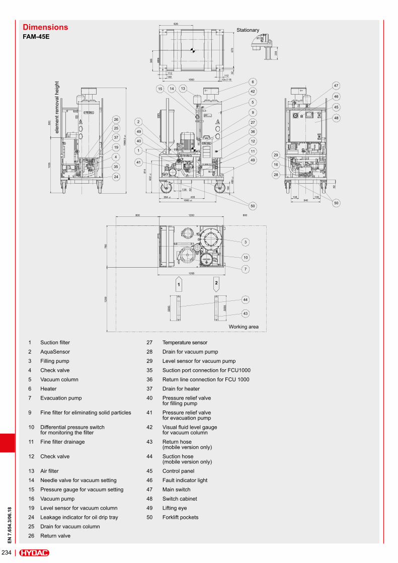
FAM-45E
elem
ent r
emov
al h
eigh
t
Dimensions
1 Suction filter 27 Temperature sensor
2 AquaSensor 28 Drain for vacuum pump
3 Filling pump 29 Level sensor for vacuum pump
4 Check valve 35 Suction port connection for FCU1000
5 Vacuum column 36 Return line connection for FCU 1000
6 Heater 37 Drain for heater
7 Evacuation pump 40 Pressure relief valve for filling pump
9 Fine filter for eliminating solid particles 41 Pressure relief valve for evacuation pump
10 Differential pressure switch for monitoring the filter
42 Visual fluid level gauge for vacuum column
11 Fine filter drainage 43 Return hose (mobile version only)
12 Check valve 44 Suction hose (mobile version only)
13 Air filter 45 Control panel
14 Needle valve for vacuum setting 46 Fault indicator light
15 Pressure gauge for vacuum setting 47 Main switch
16 Vacuum pump 48 Switch cabinet
19 Level sensor for vacuum column 49 Lifting eye
24 Leakage indicator for oil drip tray 50 Forklift pockets
25 Drain for vacuum column
26 Return valve
Working area
Stationary
EN 7
.654
.3/0
6.18
235
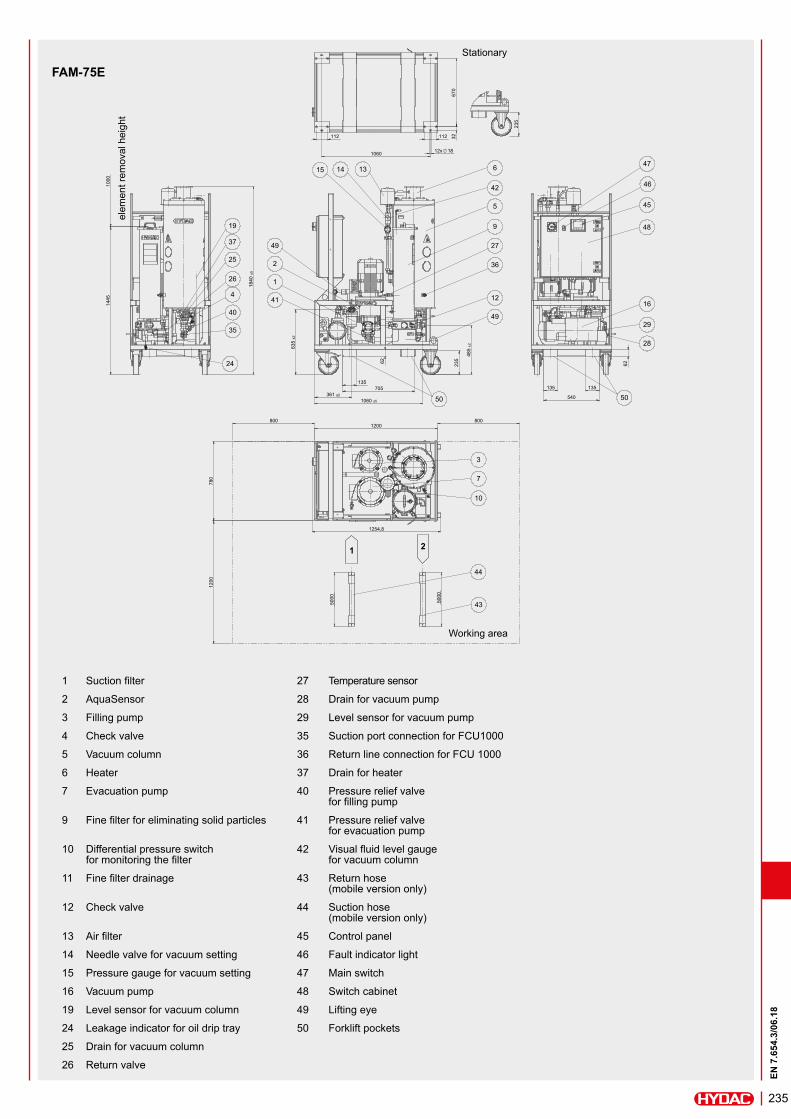
FAM-75E
1 Suction filter 27 Temperature sensor
2 AquaSensor 28 Drain for vacuum pump
3 Filling pump 29 Level sensor for vacuum pump
4 Check valve 35 Suction port connection for FCU1000
5 Vacuum column 36 Return line connection for FCU 1000
6 Heater 37 Drain for heater
7 Evacuation pump 40 Pressure relief valve for filling pump
9 Fine filter for eliminating solid particles 41 Pressure relief valve for evacuation pump
10 Differential pressure switch for monitoring the filter
42 Visual fluid level gauge for vacuum column
11 Fine filter drainage 43 Return hose (mobile version only)
12 Check valve 44 Suction hose (mobile version only)
13 Air filter 45 Control panel
14 Needle valve for vacuum setting 46 Fault indicator light
15 Pressure gauge for vacuum setting 47 Main switch
16 Vacuum pump 48 Switch cabinet
19 Level sensor for vacuum column 49 Lifting eye
24 Leakage indicator for oil drip tray 50 Forklift pockets
25 Drain for vacuum column
26 Return valve
elem
ent r
emov
al h
eigh
t
Working area
Stationary
EN 7
.654
.3/0
6.18
236
NoteThe information in this brochure relates to the operating conditions and applications described.For fields of application or operating conditions not described, please contact the relevant technical department.Subject to technical modifications.
HYDAC FILTER SYSTEMS GMBHIndustriegebiet D-66280 Sulzbach / Saar, Germany Tel.: +49 (0) 6897/509-01 Fax: +49 (0) 6897/509-9046 Internet: www.hydac.com E-mail: [email protected]
Items supplied – FluidAqua Mobil, ready-for-connection – With suction and return hose on mobile version – Vacuum pump oil (1 litre) for initial filling of rotary vane vacuum pump – Key to the control cabinet – Connection adapter (see FAM connection summary) – Technical documentation consisting of: - Operation and maintenance instructions - Electrical wiring diagram - Test certificate - CE Declaration of Conformity
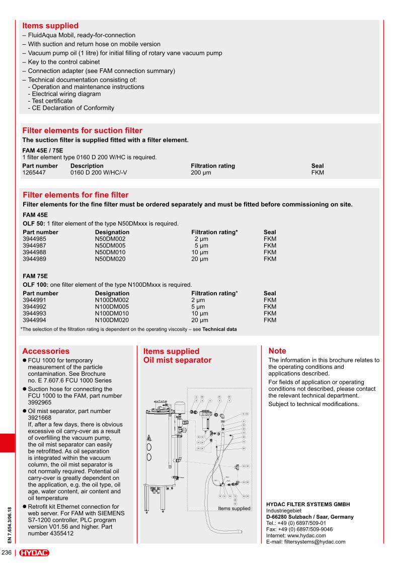
Accessories z FCU 1000 for temporary measurement of the particle contamination. See Brochure no. E 7.607.6 FCU 1000 Series zSuction hose for connecting the FCU 1000 to the FAM, part number 3992965 zOil mist separator, part number 3921668 If, after a few days, there is obvious excessive oil carry-over as a result of overfilling the vacuum pump, the oil mist separator can easily be retrofitted. As oil separation is integrated within the vacuum column, the oil mist separator is not normally required. Potential oil carry-over is greatly dependent on the application, e.g. the oil type, oil age, water content, air content and oil temperature zRetrofit kit Ethernet connection for web server. For FAM with SIEMENS S7-1200 controller, PLC program version V01.56 and higher. Part number 4355412
Items supplied Oil mist separator
Filter elements for fine filterFilter elements for the fine filter must be ordered separately and must be fitted before commissioning on site.FAM 45EOLF 50: 1 filter element of the type N50DMxxx is required. Part number Designation Filtration rating* Seal 3944985 N50DM002 2 μm FKM 3944987 N50DM005 5 μm FKM 3944988 N50DM010 10 μm FKM 3944989 N50DM020 20 μm FKM
FAM 75EOLF 100: one filter element of the type N100DMxxx is required.Part number Designation Filtration rating* Seal 3944991 N100DM002 2 μm FKM 3944992 N100DM005 5 μm FKM 3944993 N100DM010 10 μm FKM 3944994 N100DM020 20 μm FKM
Filter elements for suction filterThe suction filter is supplied fitted with a filter element. FAM 45E / 75E 1 filter element type 0160 D 200 W/HC is required. Part number Description Filtration rating Seal 1265447 0160 D 200 W/HC/-V 200 µm FKM
20 40
30
50 60 70
90
80
100
110
120
140
130
150
160170180
200
190
210
220
230
240
250
260 260 290
270
300
300
300
280
320
Port 1 Port 3
Port 2
105106
310
Items supplied
*The selection of the filtration rating is dependent on the operating viscosity – see Technical data