Embed Size (px)
Citation preview
A Laboratory Manual for
Fluid Power Engineering
(2151903)
5th Semester
Mechanical Engineering
DARSHAN INSTITUTE OF
ENGINEERING AND TECHNOLOGY,
RAJKOT
Campus: At Hadala, Rajkot-Morbi Highway, Near Water Sump, Rajkot 363650
Phone: +91-2822-293010 Web: www.dashan.ac.in

DARSHAN INSTITUTE OF ENGINEERING
AND TECHNOLOGY
Department of Mechanical Engineering - 5th Semester
Fluid Power Engineering (2151903)
List of Experiments
Sr. No.
Objective Date of
Performance Date of
submission Assessment
Marks Sign &
Remarks
1. To Study of hydraulic force.
2. To Study the operation of a Pelton Turbine.
3. To study the operation of a Francis Turbine.
4. To Study of centrifugal pump characteristics.
5. To Study of reciprocating pumps characteristics.
6. To study the operation of a double stage air compressor.
TOTAL MARKS (Average of 6 Experiment out of 10)

Impact of Jet on Vanes
Fluid Power Engineering (2151903) Department of Mechanical Engineering Darshan Institute of Engineering and Technology, Rajkot
1-1
Experiment No. 1
1.1 Aim
To study the effect of force on following type of vanes:
1. Hemispherical Vane
2. Flat Plate Vane
1.2 Introduction
If a vertical water jet moving with velocity ‘V’ is made to strike a target, which is free to
move in the vertical direction, then a force will be exerted by the jet, according to
momentum equation, this force must be equal to the rate of change of momentum of the
jet flow in the same direction.
Due to impact of the jet on the flat stationary plate, the entire velocity of the jet is
destroyed and due to the rate of change of momentum, force acts on the plate. The jet
after striking will move along the plate. But the plate is at right angles to the jet. Hence
the components of the velocity of the jet in the direction of the jet after striking will be
zero.
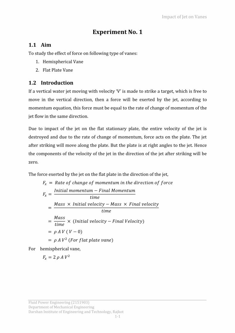
The force exerted by the jet on the flat plate in the direction of the jet,
For hemispherical vane,

Impact of Jet on Vanes
Fluid Power Engineering (2151903) Department of Mechanical Engineering Darshan Institute of Engineering and Technology, Rajkot 1-2
1.3 Nomenclature
A Area of measuring tank m2
a Cross section area of nozzle m2
d Diameter of nozzle m
Fth Theoretical force N
Fx Rate of change of momentum (Actual force) N
Q Actual discharge m3/sec
R Rise of water level in measuring tank m
R1 Final height of water in measuring tank after time t cm
R2 Initial height of water in measuring tank cm
t Time for flow measurement sec
V Velocity of jet m/sec
W Total weight kg
WA Weight applied on the disc kg
WD+R Weight of aluminum disc with rod kg
WF Weight of flat plate vane kg
WH Weight of hemispherical vane kg
Density of water kg/m3
1.4 Block Diagram
Figure 1.1 Experimental apparatus

Impact of Jet on Vanes
Fluid Power Engineering (2151903) Department of Mechanical Engineering Darshan Institute of Engineering and Technology, Rajkot
1-3
(V1-flow control valve, V2-bypass valve,
V3-drain valve of sump tank, V4-drain valve of measuring tank)
Figure 1.2 Impact of jet on vanes
1.5 Description
The setup consists of a sump tank with centrifugal pump to circulate water. A chamber
with two side glass is provided for visualization of impact of jet on vanes. Water from
sump tank flows through a nozzle and strikes vertically to vane positioned above the
nozzle. Two types of vanes (Hemispherical /Flat) are provided that can be fixed one at a
time. Arrangement is made for the movement of the plate of the vane under the action
of the jet and also because of the weight placed on the loading pan. Measuring tank and
stop watch is provided for flow measurement.
1.6 Utilities Required
Electricity Supply: Single Phase, 220 V AC, 50 Hz, 5-15 Amp. Combined socket
with earth connection.
Water Supply (Initial fill) and floor Drain Required.
Floor Area Required: 1.5 m 0.75 m.
Impact of Jet on Vanes
Fluid Power Engineering (2151903) Department of Mechanical Engineering Darshan Institute of Engineering and Technology, Rajkot 1-4
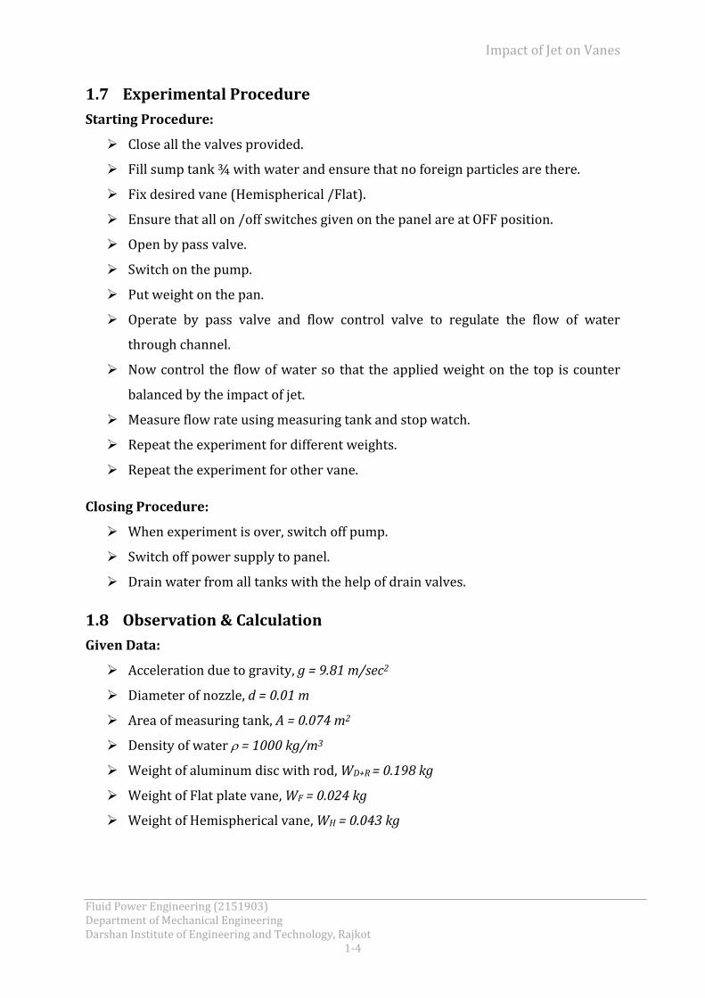
1.7 Experimental Procedure
Starting Procedure:
Close all the valves provided.
Fill sump tank ¾ with water and ensure that no foreign particles are there.
Fix desired vane (Hemispherical /Flat).
Ensure that all on /off switches given on the panel are at OFF position.
Open by pass valve.
Switch on the pump.
Put weight on the pan.
Operate by pass valve and flow control valve to regulate the flow of water
through channel.
Now control the flow of water so that the applied weight on the top is counter
balanced by the impact of jet.
Measure flow rate using measuring tank and stop watch.
Repeat the experiment for different weights.
Repeat the experiment for other vane.
Closing Procedure:
When experiment is over, switch off pump.
Switch off power supply to panel.
Drain water from all tanks with the help of drain valves.
1.8 Observation & Calculation
Given Data:
Acceleration due to gravity, g = 9.81 m/sec2
Diameter of nozzle, d = 0.01 m
Area of measuring tank, A = 0.074 m2
Density of water = 1000 kg/m3
Weight of aluminum disc with rod, WD+R = 0.198 kg
Weight of Flat plate vane, WF = 0.024 kg
Weight of Hemispherical vane, WH = 0.043 kg
Impact of Jet on Vanes
Fluid Power Engineering (2151903) Department of Mechanical Engineering Darshan Institute of Engineering and Technology, Rajkot
1-5
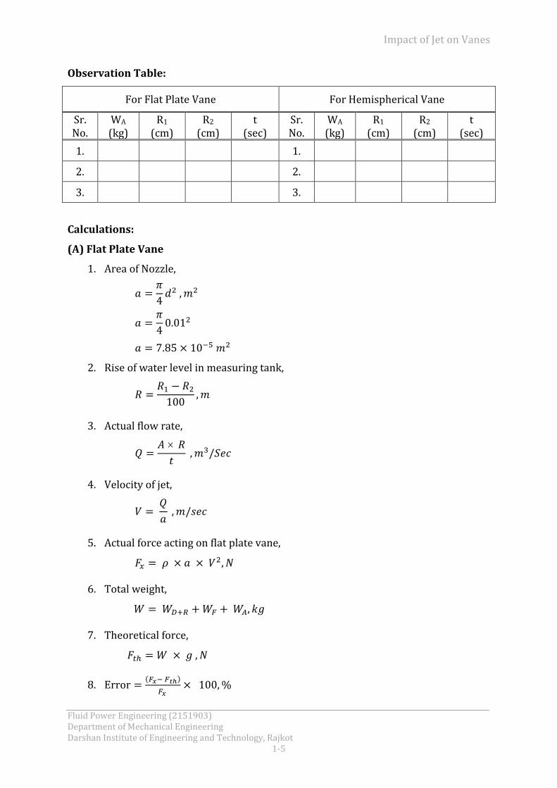
Observation Table:
For Flat Plate Vane For Hemispherical Vane
Sr. No.
WA (kg)
R1 (cm)
R2 (cm)
t (sec)
Sr. No.
WA (kg)
R1 (cm)
R2 (cm)
t (sec)
1. 1.
2. 2.
3. 3.
Calculations:
(A) Flat Plate Vane
1. Area of Nozzle,
2. Rise of water level in measuring tank,
3. Actual flow rate,
4. Velocity of jet,
5. Actual force acting on flat plate vane,
6. Total weight,
7. Theoretical force,
8.

Impact of Jet on Vanes
Fluid Power Engineering (2151903) Department of Mechanical Engineering Darshan Institute of Engineering and Technology, Rajkot 1-6
(B) Hemispherical Vane
1. Area of Nozzle,
2. Rise of water level in measuring tank,
3. Actual flow rate,
4. Velocity of jet,
5. Actual force acting on hemispherical vane,
6. Total weight,
7. Theoretical force,
8.
Result Table:
(A) For Flat Plate Vane
Sr. No.
R (m)
Q (m3/sec)
V (m/sec)
Fx (N)
W (Kg)
Fth (N)
Error (%)
1.
2.
3.
Impact of Jet on Vanes
Fluid Power Engineering (2151903) Department of Mechanical Engineering Darshan Institute of Engineering and Technology, Rajkot
1-7
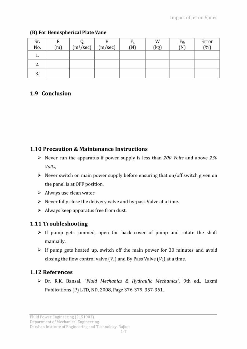
(B) For Hemispherical Plate Vane
Sr. No.
R (m)
Q (m3/sec)
V (m/sec)
Fx (N)
W (kg)
Fth (N)
Error (%)
1.
2.
3.
1.9 Conclusion
1.10 Precaution & Maintenance Instructions
Never run the apparatus if power supply is less than 200 Volts and above 230
Volts,
Never switch on main power supply before ensuring that on/off switch given on
the panel is at OFF position.
Always use clean water.
Never fully close the delivery valve and by-pass Valve at a time.
Always keep apparatus free from dust.
1.11 Troubleshooting
If pump gets jammed, open the back cover of pump and rotate the shaft
manually.
If pump gets heated up, switch off the main power for 30 minutes and avoid
closing the flow control valve (V1) and By Pass Valve (V2) at a time.
1.12 References
Dr. R.K. Bansal, “Fluid Mechanics & Hydraulic Mechanics”, 9th ed., Laxmi
Publications (P) LTD, ND, 2008, Page 376-379, 357-361.

Pelton Wheel Turbine Test Rig
Fluid Power Engineering (2151903) Department of Mechanical Engineering Darshan Institute of Engineering and Technology, Rajkot
2- 1
Experiment No. 2
2.1 Aim
To Study the operation of a Pelton Turbine:
1. To determine the output power of Pelton turbine.
2. To determine the efficiency of the Pelton turbine.
2.2 Introduction
A turbine is a machine which converts the fluid energy into mechanical energy which is
then utilized to run the electric generator of a power plant. Pelton turbine is an impulse
turbine. In an impulse turbine, all the available energy of water is converted into kinetic
energy or velocity head by passing it through a contracting nozzle provided at the end of
the penstock. The water coming out of the nozzle is formed into a free jet, which strikes
on a series of buckets of the runner thus causing it to revolve. The runner revolves
freely in air and the pressure at the inlet and outlet of the turbine is atmosphere. The
water is contact with only a part of the runner at a time, and throughout its action on
the runner. The turbine is used for high head.
2.3 Nomenclature
A Cross section area of pipe m2
Cv Co-efficient of pitot tube.
D Diameter of pipe M
dB Diameter of brake drum m
dR Diameter of rope m
Ei Input power kW
Eo Output power kW
g Acceleration due to gravity m/sec2
H Total head m
h Manometer difference m
h1,h2 Manometer reading at both points cm
N RPM of runner shaft RPM
P Pressure gauge reading kg/cm2
Re Equivalent Radius m

Pelton Wheel Turbine Test Rig
Fluid Power Engineering (2151903) Department of Mechanical Engineering Darshan Institute of Engineering and Technology, Rajkot
2-2
Q Discharge m3/sec
T Torque N m
V Velocity of water m/sec
W1 Spring balance weight kg
W2 Adjustable weight kg
W3 Weight of Rope kg
w Density of Water kg/m3
m Density of Manometer fluid i.e. Hg kg/m3
ηt Turbine efficiency %
2.4 Block Diagram
(V1 – bypass valve, V2 – valve for cooling water or brake drum, V3 – drain valve for
sump tank, V4 & V5 – valve for manometer for pressure tapping,
V6 & V7 – valve on manometer for air vent)
Figure 2.1 Pelton wheel turbine test rig
Pelton Wheel Turbine Test Rig
Fluid Power Engineering (2151903) Department of Mechanical Engineering Darshan Institute of Engineering and Technology, Rajkot
2- 3
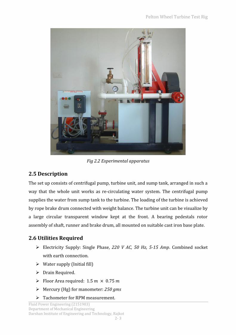
Fig 2.2 Experimental apparatus
2.5 Description
The set up consists of centrifugal pump, turbine unit, and sump tank, arranged in such a
way that the whole unit works as re-circulating water system. The centrifugal pump
supplies the water from sump tank to the turbine. The loading of the turbine is achieved
by rope brake drum connected with weight balance. The turbine unit can be visualize by
a large circular transparent window kept at the front. A bearing pedestals rotor
assembly of shaft, runner and brake drum, all mounted on suitable cast iron base plate.
2.6 Utilities Required
Electricity Supply: Single Phase, 220 V AC, 50 Hz, 5-15 Amp. Combined socket
with earth connection.
Water supply (Initial fill)
Drain Required.
Floor Area required:
Mercury (Hg) for manometer: 250 gms
Tachometer for RPM measurement.
Pelton Wheel Turbine Test Rig
Fluid Power Engineering (2151903) Department of Mechanical Engineering Darshan Institute of Engineering and Technology, Rajkot
2-4
2.7 Experimental Procedure
Starting Procedure:
Close all the valves provided.
Fill sump tank ¾th with clean water and ensure that no foreign particles are
there.
Fill manometer fluid i.e. Hg. in manometer by opening the valves of manometer
and one PU pipe from pressure measurement point of pipe.
Connect the PU pipe back to its position and close the valves of manometer.
Open the by-pass valve and ensure that there is no load on the brake drum.
Switch on the pump with the help of starter.
Close the by-pass valve.
Open pressure measurement valves of the manometer.
Open the air release valve provided on the manometer, slowly to release the air
from manometer. (This should be done very carefully)
When there is no air in the manometer, close the air release valves.
Now turbine is in operation.
Load the turbine with the help of hand wheel attached on the top of weight
balance.
Note the manometer reading and pressure gauge reading.
Measure the load applied and RPM of the turbine.
Repeat the experiment at different load.
Repeat the experiment for different discharge by regulating the nozzle position
by the hand wheel provided for same.
Closing Procedure:
When the experiment is over, first of all remove the load on dynamometer.
Open the by-pass valve.
Close the ball valves provided on manometer.
Switch OFF Pump with the help of starter.
Switch OFF main power supply.
Drain the sump tank by the drain valve provided.

Pelton Wheel Turbine Test Rig
Fluid Power Engineering (2151903) Department of Mechanical Engineering Darshan Institute of Engineering and Technology, Rajkot
2- 5
2.8 Observation & Calculation Given Data:
Acceleration due to gravity, g = 9.81 m/sec2
Diameter of pipe, D = 0.052 m
Density of water, w = 1000 kg/m3
Diameter of brake drum, dB = 0.2 m
Density of Manometer fluid Hg, m = 13600 kg/m3
Diameter of rope, dR = 0.012 m
Co-efficient velocity for pitot tube, Cv = 0.98
Weight of Rope, W3 = 0.116 kg
Observation Table:
Sr. No
N RPM
P kg/cm2
h1 (cm)
h2 (cm)
W1 (kg)
W2 (kg)
1.
2.
3.
4.
5.
Calculations:
1. Total head,
2. Cross section area of pipe,
3. Manometer difference,
4. Velocity of water,

Pelton Wheel Turbine Test Rig
Fluid Power Engineering (2151903) Department of Mechanical Engineering Darshan Institute of Engineering and Technology, Rajkot
2-6
√ ( )
5. Discharge,
6. Input power,
7. Equivalent radius,
8. Torque,
( )
9. Output power,
10. Turbine efficiency,
Result Table:
Sr. No
H, (m of WC)
Q (m3/sec)
EI
(kW) T
(Nm) Eo
(kW) ηt
(%)
1.
2.
3.
4.
5.
2.9 Conclusion
Pelton Wheel Turbine Test Rig
Fluid Power Engineering (2151903) Department of Mechanical Engineering Darshan Institute of Engineering and Technology, Rajkot
2- 7
2.10 Precaution & Maintenance Instructions
Never run the apparatus if power supply is less than 390 volts and above 420
volts.
To prevent clogging of moving parts, run pump at least once in a fortnight.
Always keep apparatus free from dust.
2.11 Troubleshooting
If pump does not lift the water, the revolution of the motor may be reverse.
Change the electric connection to change the revolutions.
If panel is not showing input, check the main supply.
2.12 References
Streeter, Wylie, Bedford, “Fluid Mechanics”, 9th ed., McGraw Hill., NY, 2007, Page
529-532.
Y.A.Cengel, J.M. Cimbala, “Fluid Mechanics”, 2nd ed., Tata McGraw-Hill, ND, 2007,
Page 783-785.

Francis Turbine Test Rig
Fluid Power Engineering (2151903) Department of Mechanical Engineering Darshan Institute of Engineering and Technology, Rajkot
3- 1
Experiment No. 3
3.1 Aim
To study the operation of a Francis Turbine:
1. To determine the output power of Francis Turbine.
2. To determine the efficiency of the Francis Turbine.
3.2 Introduction
Francis Turbine, named after James Bichens Fransis, is a reaction type of turbine for
medium high to medium low heads and medium small to medium large quantities of
water. The reaction turbine operates with its wheel submerged in water. It is a mixed
flow type in which water enters the runner radially inwards towards the centre and
discharges out axially. The water before entering the turbine has pressure as well as
kinetic energy. The moment on the wheel is produced by both kinetic and pressure
energies. The water leaving the turbine has still some of the pressure as well as kinetic
energy.
3.3 Nomenclature
A Cross section area of pipe m2
Cv Co-efficient of pitot tube
D Diameter of pipe m
dB Diameter of brake drum m
dR Diameter of rope m
Ei Input power kW
Eo Output power kW
g Acceleration due to gravity m/sec2
H Total head m
h Differential pressure of manometer m
h1,h2 Manometer reading at both points cm
N RPM of runner shaft RPM
Pd Delivery pressure kg/cm2
PS Suction pressure mmHg

Francis Turbine Test Rig
Fluid Power Engineering (2151903) Department of Mechanical Engineering Darshan Institute of Engineering and Technology, Rajkot 3-2
Q Discharge m3/sec
Re Equivalent Radius m
T Torque N m
V Velocity of water m/sec
W1 Applied weight kg
W2 Dead weight (obtain from spring balance) kg
W3 Weight of hanger kg
W4 Weight of Rope kg
w Density of Water kg/m3
m Density of Manometer fluid i.e. Hg kg/m3
ηt Turbine efficiency %
3.4 Block Diagram
(V1 - valve for discharge pressure, V2 - valve for suction pressure, V3 & V4 - valve for
pitot tube, V5 & V6 – Air bleeding valve, V7 – Drain valve for sump tank,
V8 – valve for cooling water of brake drum)
Figure 3.1 - Francis turbine test rig

Francis Turbine Test Rig
Fluid Power Engineering (2151903) Department of Mechanical Engineering Darshan Institute of Engineering and Technology, Rajkot
3- 3
Figure 3.2 – Experimental apparatus
3.5 Description
The present set-up consists of a runner. The water is fed to the turbine by means of
Centrifugal Pump, radially to the runner. The runner is directly mounted on one end of a
central SS shaft and other end is connected to a brake arrangement. The circular
window of the turbine casing is provided with a transparent acrylic sheet for
observation of flow on to the runner. This runner assembly is supported by thick cast
iron pedestal. Load is applied to the turbine with the help of brake arrangement so that
the efficiency of the turbine can be calculated. A draught tube is fitted on the outlet of
the turbine. The set-up is complete with guide mechanism. Pressure and vacuum gauges
are fitted at the inlet and outlet of the turbine to measure the total supply head on the
turbine.
3.6 Utilities Required
Electricity Supply: Three Phase, 440 V AC, 50 Hz, 5kW with earth connection.
Water supply (200 liters.)
Drain required.
Floor Area required: 2 m x 1 m
Francis Turbine Test Rig
Fluid Power Engineering (2151903) Department of Mechanical Engineering Darshan Institute of Engineering and Technology, Rajkot 3-4
Mercury for manometer, 250 gm.
Tachometer to measure RPM
3.7 Experimental Procedure
Starting Procedure:
Clean the apparatus and make tank free from Dust.
Close the drain valve provided.
Fill Sump tank ¾ with Clean Water and ensure that no foreign particles are there.
Fill manometer fluid i.e. Hg. in manometer by opening the valves of manometer
and one PU pipe from pressure measurement point of pipe.
Connect the PU pipe back to its position and close the valves of manometer.
Ensure that there is no load on the brake drum.
Switch on the Pump with the help of Starter.
Open the Air release valve provided on the Manometer, slowly to release the air
from manometer. (This should be done very carefully.)
When there is no air in the manometer, close the air release valves.
Now turbine is in operation.
Apply load on hanger and adjust the spring balance load by hand wheel just to
release the rest position of the hanger.
Note the manometer reading, pressure gauge reading and vacuum gauge reading.
Measure the RPM of the turbine.
Note the applied weight and spring balance reading.
Repeat the same experiment for different load.
Regulate the discharge by regulating the guide vanes position.
Repeat the experiment for different discharge.
Closing Procedure:
When the experiment is over, first remove load on dynamometer.
Open the by-pass valve.
Close the ball valves provided on manometer.
Switch OFF Pump with the help of starter.
Switch OFF main power supply.
Francis Turbine Test Rig
Fluid Power Engineering (2151903) Department of Mechanical Engineering Darshan Institute of Engineering and Technology, Rajkot
3- 5
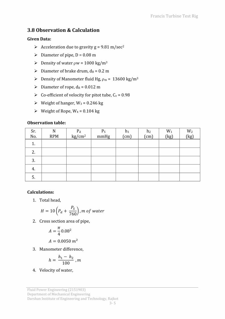
3.8 Observation & Calculation
Given Data:
Acceleration due to gravity g = 9.81 m/sec2
Diameter of pipe, D = 0.08 m
Density of water w = 1000 kg/m3
Diameter of brake drum, dB = 0.2 m
Density of Manometer fluid Hg, m = 13600 kg/m3
Diameter of rope, dR = 0.012 m
Co-efficient of velocity for pitot tube, Cv = 0.98
Weight of hanger, W3 = 0.246 kg
Weight of Rope, W4 = 0.104 kg
Observation table:
Sr. No.
N RPM
Pd kg/cm2
PS mmHg
h1 (cm)
h2 (cm)
W1 (kg)
W2 (kg)
1.
2.
3.
4.
5.
Calculations:
1. Total head,
(
)
2. Cross section area of pipe,
3. Manometer difference,
4. Velocity of water,

Francis Turbine Test Rig
Fluid Power Engineering (2151903) Department of Mechanical Engineering Darshan Institute of Engineering and Technology, Rajkot 3-6
√ ( )
5. Discharge,
6. Input power,
7. Equivalent radius,
8. Torque,
( )
9. Output power,
10. Turbine efficiency,
Result Table:
Sr. No
H, (m of WC)
Q (m3/sec)
EI
(kW) T
(Nm) Eo
(kW) ηt
(%)
1.
2.
3.
4.
5.
3.9 Conclusion
Francis Turbine Test Rig
Fluid Power Engineering (2151903) Department of Mechanical Engineering Darshan Institute of Engineering and Technology, Rajkot
3- 7
3.10 Precaution & Maintenance Instructions
Never run the apparatus if power supply is less than 390 volts and above 420
volts
To prevent clogging of moving parts, Run Pump at least once in a fortnight.
Always use clean water.
Drain the apparatus completely after experiment is over.
Always keep apparatus free from dust.
3.11 Troubleshooting
If pump does not lift the water, the revolution of the motor may be reverse.
Change the electric connection to change the revolutions.
If panel is not showing input, check the main supply.
3.12 References
Streeter, Wylie, Bedford, “Fluid Mechanics”, 9th ed., McGraw Hill., NY, 2007, Page
518-520.
Y.A. Cengel, J.M. Cimbala,”Fluiod Mechanics”, 2nd ed., Tata McGraw-Hill, ND,
2007, Page 786-795.


Centrifugal Pump Test Rig
Fluid Power Engineering (2151903) Department of Mechanical Engineering Darshan Institute of Engineering and Technology, Rajkot
4- 1
Experiment No. 4
4.1 Objective
Study of centrifugal pump characteristics.
4.2 Aim
1. To determine : (i) Power input, (ii) Shaft output, (iii) Discharge, (iv) Total head,
(v) Pump Output, (vi) Overall efficiency, (vii) Pump efficiency
2. To plot the following performance characteristics: (i) Head Vs Discharge, (ii)
Pump efficiency Vs Discharge
4.3 Introduction
The hydraulic machines, which convert the mechanical energy into hydraulic energy,
are called pumps. The hydraulic energy is in the form of pressure energy. If the
mechanical energy is converted into pressure energy by means of centrifugal force
acting on the fluid, the hydraulic machine is called centrifugal pump.
The centrifugal pump acts as a reversed of an inward radial flow reaction turbine. This
means that the flow in centrifugal pumps is in the radial outward directions. The
centrifugal pump works on the principle of forced vortex flow, which means that an
external torque rotates a certain mass of liquid, the rise in pressure head of the rotating
liquid takes place. The rise in pressure head at any point of the rotating liquid is
proportional to the square of tangential velocity of (i.e. rise in pressure head = V2/ 2g or
2r2/2g) the liquid at that point. Thus at the outlet of the impeller where radius is more,
the rise in pressure head will be more and the liquid will be discharged at the outlet
with a high- pressure head. Due to this high-pressure head, the liquid can be lifted to a
high level.
Centrifugal Pump is a mechanical device, which consists of a body, impeller and a
rotating mean i.e. motor, engine etc. Impeller rotates in a stationary body and sucks the
fluid through its axes and delivers through its periphery. Impeller has an inlet angle,
outlet angle and peripheral speed, which affect the head and discharge. Impeller is
rotated by motor or i.c. engine or any other device.

Centrifugal Pump Test Rig
Fluid Power Engineering (2151903) Department of Mechanical Engineering Darshan Institute of Engineering and Technology, Rajkot
4-2
4.4. Nomenclature
A Area of measuring tank m2
EMC Energy meter constant Pulses/kW hr
Ei Pump input kW
ES Shaft output kW
Eo Pump output kW
g Acceleration due to gravity m/s2
H Total head m
hpg Height of pressure gauge from vacuum gauge m
N Speed of pump RPM
P Pulses of energy meter
Pd Delivery pressure kg/cm2
PS Suction pressure mmHg
Q Discharge m3/s
R Rise of water level in measuring tank m
R1 Final level of water in measuring tank cm
R2 Initial level of water in measuring tank cm
t Time taken by R sec
tp Time taken by P sec
Density of fluid kg/m3
ηm Motor efficiency %
ηo overall efficiency %
ηp Pump efficiency %
Centrifugal Pump Test Rig
Fluid Power Engineering (2151903) Department of Mechanical Engineering Darshan Institute of Engineering and Technology, Rajkot
4- 3
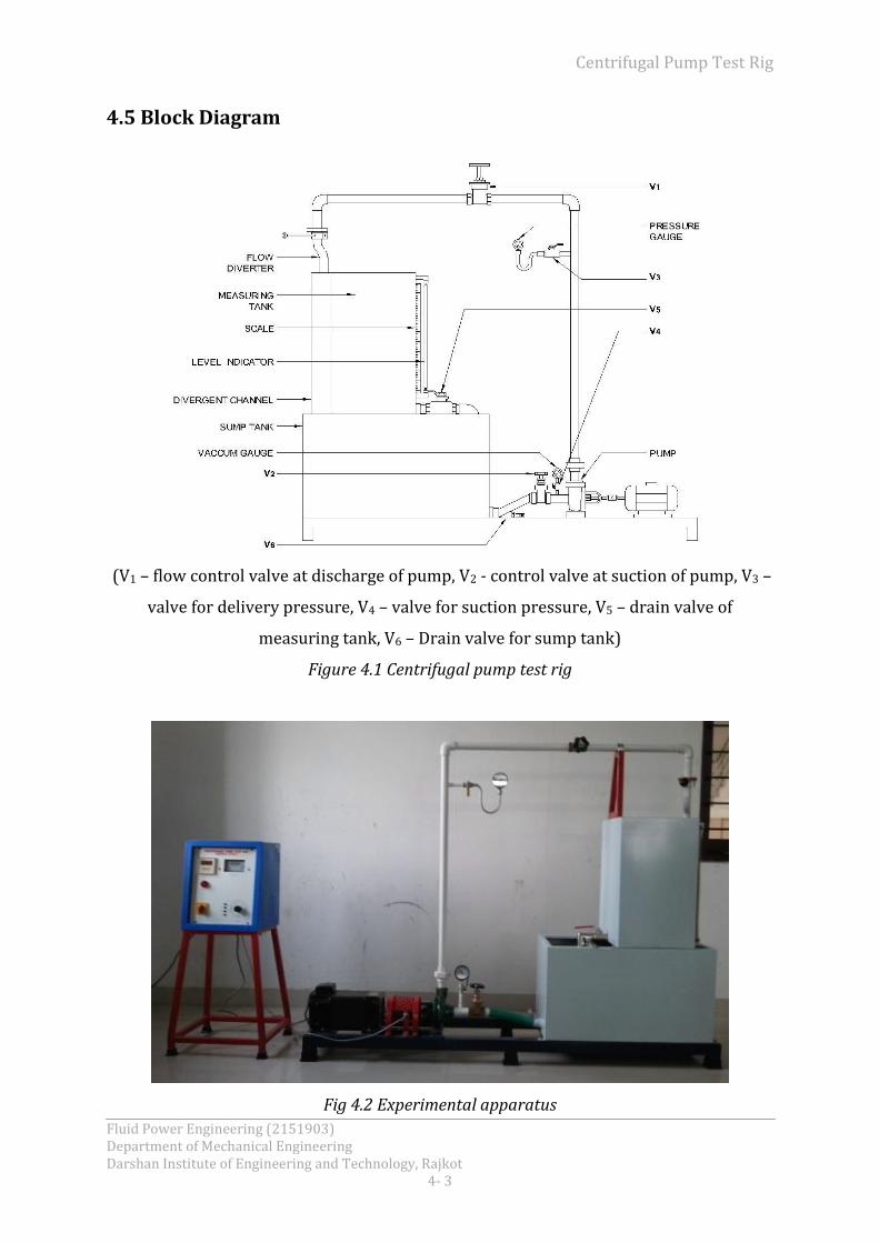
4.5 Block Diagram
(V1 – flow control valve at discharge of pump, V2 - control valve at suction of pump, V3 –
valve for delivery pressure, V4 – valve for suction pressure, V5 – drain valve of
measuring tank, V6 – Drain valve for sump tank)
Figure 4.1 Centrifugal pump test rig
Fig 4.2 Experimental apparatus

Centrifugal Pump Test Rig
Fluid Power Engineering (2151903) Department of Mechanical Engineering Darshan Institute of Engineering and Technology, Rajkot
4-4
4.6 Description
Centrifugal Pump Test Rig consists of a sump, a centrifugal pump, a DC motor and
measuring tank. To measure the head, pressure and vacuum gauges are provided. To
measure the discharge, a measuring tank is provided. Flow diversion system is provided
to divert flow from sump tank to measuring tank and from measuring tank to sump
tank. A valve is provided in pipeline to change the rate of flow.
4.7 Utilities Required
Electricity Supply: Single Phase, 220 V AC, 50 Hz, 5-15 Amp.
Combined socket with earth connection.
Water Supply (Initial Fill).
Floor Drain Required.
Floor Area Required:
4.8 Experimental Procedure
Starting Procedure:
Clean the apparatus and make tanks free from dust.
Close the drain valves provided.
Fill sump tank ¾ with clean water and ensure that no foreign particles are there.
Open flow control valve given on the water discharge line and control valve
given on suction line.
Ensure that all On/Off switches given on the panel are at OFF position.
Set the desired RPM of motor / pump with the speed control knob provided at
the control panel.
Operate the flow control valve to regulate the flow of water discharged by the
pump.
Operate the control valve to regulate the suction of the pump.
Record discharge pressure by means of pressure gauge, provided on discharge
line.
Record suction pressure by means of vacuum gauge, provided at suction of the
pump.
Record the power consumption by means of energy meter, provided in panel
with the help of stop watch.

Centrifugal Pump Test Rig
Fluid Power Engineering (2151903) Department of Mechanical Engineering Darshan Institute of Engineering and Technology, Rajkot
4- 5
Measure the discharged by using measuring tank and stop watch.
Repeat the same procedure for different speeds of pump.
Repeat the same procedure for different discharge with constant speed.
Closing Procedure:
When experiment is over, open gate valve properly provided on the discharge
line.
Reduce the RPM of the pump with the help of DC drive.
Switch OFF the pump first.
Switch OFF power supply to panel.
4.9 Observation & Calculation
Given Data:
Area of measuring tank A = 0.125 m2
Acceleration due to gravity, g = 9.81 m/sec2
Motor Efficiency, ηm = 0.8 (assumed)
Density of water = 1000 kg/m3
Energy Meter Constant, EMC = 3200 Pulses / kW hr
Height of pressure gauge from vacuum gauge, hpg = 1 m
Observation Table:
Sr. No
N (RPM)
Pd (kg/cm2)
PS (mmHg)
R1 (cm)
R2 (cm)
t (sec)
tP (sec)
P
1.
2.
3.
4.
5.
Calculations:
1. Pump input,
2. Shaft output,

Centrifugal Pump Test Rig
Fluid Power Engineering (2151903) Department of Mechanical Engineering Darshan Institute of Engineering and Technology, Rajkot
4-6
3. Rise of water level in measuring tank,
4. Discharge,
⁄
5. Total head,
[
]
6. Pump output,
7. Pump efficiency,
8. Overall efficiency,
Result Table:
Sr. No
N (RPM)
H (m of
water)
Q (m3/sec)
EI
(kW) Es
(kW) Eo
(kW) ηp
(%) ηo
(%)
1.
2.
3.
4.
5.
Centrifugal Pump Test Rig
Fluid Power Engineering (2151903) Department of Mechanical Engineering Darshan Institute of Engineering and Technology, Rajkot
4- 7
4.10 Conclusion
4.11 Precaution & Maintenance Instructions
Never run the apparatus if power supply is less than 200Volts and above 230
Volts
Never fully close the Delivery line and By-Pass line Valves simultaneously.
To prevent clogging of moving parts, Run Pump at least once in a fortnight
Always use clean water.
If apparatus will not in use for more than half month, drain the apparatus
completely.
Always keep apparatus free from dust.
4.12 Troubleshooting
If pump does not lift the water, open the air vent provided on the pump to
remove the air from pump.
If still water is not lifting the revolution of the DC motor may be reverse. Change
the electric connection of motor to change the revolutions.
If panel is not showing input, check the fuse and main supply.
If field failure (FF) indicates on the control panel and the motor is not moving,
check the fuses if burnt, change it.
If overload (OL) indicates on the panel and motor stop moving, reduce the load.
4.13 References
R.S Khurmi, “Hydraulics, Fluid Mechanics and Hydraulic Machines”, 11th ed.,
S.Chand & Company LTD., ND, 2008, Page 582-585, 587, 590.
Y.A. Cengel, J.M. Cimbala, ”Fluid Mechanics”, 2nd ed., Tata McGraw-Hill, ND, 2007,
Page180-182.

Reciprocating Pump Test Rig
Fluid Power Engineering (2151903) Department of Mechanical Engineering Darshan Institute of Engineering and Technology, Rajkot
5- 1
Experiment No. 5
5.1 Objective
Study of reciprocating pumps characteristics.
5.2 Aim
1. To determine: (i) Power input, (ii) Shaft output, (iii) Total head, (iv) Discharge,
(v) Pump Output, (vi) Overall efficiency, (vii) Volumetric efficiency, (viii) Pump
efficiency
2. To plot the following performance characteristics: (i) Head Vs Discharge, (ii)
Pump efficiency Vs Discharge
5.3 Introduction
A pump is a device which lifts water from a lower level to a higher level at the expense
of mechanical energy. Pump can be broadly classified into two categories, Positive
Displacement & rotodynamic or dynamic pressure pump. In a positive displacement
pump a small quantity of liquid is taken inside the pump and is bodily displaced and
forced out of the pump under pressure. The liquid inside a positive displacement pump
may be subjected either to a reciprocating motion (reciprocating pump) or to a
rotary/circular motion (gear pump, screw pumps etc.).
Reciprocating Pump consists a piston having a reciprocatory motion inside a cylinder
with the help of connecting rod and a crank rotated by a electric motor, I.C. Engine, or
any another suitable means. The cylinder is connected to the sump by the suction pipe
and to the reservoir by the delivery pipe. Valves are provided at suction and delivery
side and are non-returnable so that to allow the fluid in direction only.
These pumps are applied where the fluid is required in a small quantity but at a higher
pressure. Reciprocating pumps are applied for vehicle washing, for the water supply for
the multi-stories buildings, industries etc.

Reciprocating Pump Test Rig
Fluid Power Engineering (2151903) Department of Mechanical Engineering Darshan Institute of Engineering and Technology, Rajkot
5-2
5.4 Nomenclature
A Area of measuring tank m2
a Area of cylinder m2
d Diameter of cylinder m
EMC Energy meter constant Pulses/kW hr
Ei & Eo Pump input & output kW
ES Shaft output kW
g Acceleration due to gravity m/s2
H Total head m
hpg Height of pressure gauge from vacuum gauge m
L Length of stroke m
N Speed of pump RPM
P Pulses of energy meter
Pd Delivery pressure kg/cm2
PS Suction pressure mmHg
Qa & Qt Actual & Theoretical discharge m3/s
R Rise of water level in measuring tank m
R1 & R2 Final & Initial level of water in measuring
tank
cm
t & tp Time taken by R & P sec
Density of fluid kg/m3
ηm, ηo, ηp Motor, Overall & Pump efficiency %
ηt & ηvol Transmission & Volumetric efficiency %

Reciprocating Pump Test Rig
Fluid Power Engineering (2151903) Department of Mechanical Engineering Darshan Institute of Engineering and Technology, Rajkot
5- 3
5.5 Figure
(V1 – flow control valve, V2 – valve for suction, V3 – valve before pressure gauge, V4 –
valve before suction gauge, V5 – drain valve for measuring tank, V6 – drain valve for
sump)
Figure 5.1 Reciprocating pump test rig
Fig 5.2 Experimental apparatus
Reciprocating Pump Test Rig
Fluid Power Engineering (2151903) Department of Mechanical Engineering Darshan Institute of Engineering and Technology, Rajkot
5-4
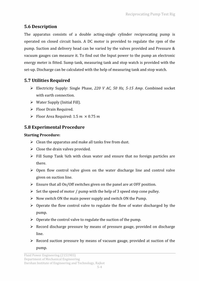
5.6 Description
The apparatus consists of a double acting-single cylinder reciprocating pump is
operated on closed circuit basis. A DC motor is provided to regulate the rpm of the
pump. Suction and delivery head can be varied by the valves provided and Pressure &
vacuum gauges can measure it. To find out the Input power to the pump an electronic
energy meter is fitted. Sump tank, measuring tank and stop watch is provided with the
set-up. Discharge can be calculated with the help of measuring tank and stop watch.
5.7 Utilities Required
Electricity Supply: Single Phase, 220 V AC, 50 Hz, 5-15 Amp. Combined socket
with earth connection.
Water Supply (Initial Fill).
Floor Drain Required.
Floor Area Required:
5.8 Experimental Procedure
Starting Procedure:
Clean the apparatus and make all tanks free from dust.
Close the drain valves provided.
Fill Sump Tank ¾th with clean water and ensure that no foreign particles are
there.
Open flow control valve given on the water discharge line and control valve
given on suction line.
Ensure that all On/Off switches given on the panel are at OFF position.
Set the speed of motor / pump with the help of 3 speed step cone pulley.
Now switch ON the main power supply and switch ON the Pump.
Operate the flow control valve to regulate the flow of water discharged by the
pump.
Operate the control valve to regulate the suction of the pump.
Record discharge pressure by means of pressure gauge, provided on discharge
line.
Record suction pressure by means of vacuum gauge, provided at suction of the
pump.

Reciprocating Pump Test Rig
Fluid Power Engineering (2151903) Department of Mechanical Engineering Darshan Institute of Engineering and Technology, Rajkot
5- 5
Note down the time required for 10 pulses with the help of stop watch to
calculate the power consumption.
Note down the RPM.
Measure the flow of water, discharged by the pump, using stop watch and
measuring tank.
Repeat the same procedure for different pressure head.
Repeat the same procedure for different RPM with the help of step cone pulley.
Closing Procedure:
When experiment is over, gate valve is proper open provided on discharge line.
Switch OFF the pump first.
Switch OFF power supply to panel (MCB).
5.9 Observation & Calculation
Given Data:
Area of measuring tank, A = 0.075 m2
Energy Meter Constant, EMC = 3200 Pulses / kW hr
Acceleration due to gravity, g = 9.81m/sec2
Height of pressure gauge from vacuum gauge, hpg = 0.650 m
Motor Efficiency, ηm = 0.8 (assumed)
Efficiency of transmission, ηt = 0.7 (assumed)
Density of water = 1000 kg/m3
Diameter of cylinder, d = 0.055 m
Length of stroke, L = 0.04 m
Observation Table:
Sr. No
N (RPM)
Pd (kg/cm2)
PS (mm of Hg)
R1 (cm)
R2 (cm)
t (sec)
tP (sec)
P
1.
2.
3.
4.
5.

Reciprocating Pump Test Rig
Fluid Power Engineering (2151903) Department of Mechanical Engineering Darshan Institute of Engineering and Technology, Rajkot
5-6
Calculations:
1. Pump input,
2. Shaft output,
3. Rise of water level in measuring tank,
4. Actual discharge,
⁄
5. Area of cylinder,
6. Theoretical discharge,
⁄
7. Total head,
[
]
8. Pump output,
9. Volumetric efficiency,
10. Pump efficiency,

Reciprocating Pump Test Rig
Fluid Power Engineering (2151903) Department of Mechanical Engineering Darshan Institute of Engineering and Technology, Rajkot
5- 7
11. Overall efficiency,
Result Table:
Sr. No
N (RPM)
Qa (m3/sec)
Qt (m3/sec)
EI
(kW) Es
(kW) Eo
(kW) ηvol (%)
ηp (%)
ηo (%)
1.
2.
3.
4.
5.
5.10 Conclusion
5.11 Precaution & Maintenance Instructions
Never run the apparatus if power supply is less than 200Volts and above 230
Volts.
Never fully close the Delivery Valve and By-Pass Valves at a time.
To prevent clogging of moving parts, Run Pump at least once a fortnight.
Always use clean water.
If apparatus is not in use for more than half month, drain the apparatus
completely.
Always keep apparatus free from dust.

Reciprocating Pump Test Rig
Fluid Power Engineering (2151903) Department of Mechanical Engineering Darshan Institute of Engineering and Technology, Rajkot
5-8
5.12 Troubleshooting
If pump does not lift the water, open the air vent provided on the pump to
remove the air from pump.
If still water is not lifted, the revolution of the DC motor may be reverse. Change
the electric connection of motor to change the revolutions.
If panel is not showing input, check the fuse and main supply.
If field failure (FF) indicates on the control panel and the motor is not moving,
check the fuses, if burnt, change it.
If overload (OL) indicates on the panel and motor stop moving, reduce the load.
5.13 References
R.S Khurmi, “Hydraulics Fluid Mechanics and Hydraulic Machines”, 11th ed.,
S.Chand & Company LTD., ND, 2008, Page 602-604, 605, 606.
Dr. P.N. Modi, Dr. S. M. Seth, “Hydraulics & Fluid Mechanics”, 15th ed., Standard
Book House, ND, 2005, Page1020-1022.

Double Stage Air Compressor Test Rig
Fluid Power Engineering (2151903) Department of Mechanical Engineering Darshan Institute of Engineering and Technology, Rajkot
6- 1
Experiment No. 6
6.1 Objective
To study the operation of a double stage air compressor.
6.2 Aim
1. To find out the volumetric efficiency
2. To find out isothermal efficiency
3. To calculate the compression ratio
6.3 Nomenclature
ao Cross section area of orifice m2
ap Cross section area of pipe m2
Cd Co-efficient of discharge of orifice
d Diameter of bore m
do Diameter of orifice m
dp Diameter of pipe m
EMC Energy meter constant Pulses / kW hr
Ei Power input kW
Eiso Isothermal power kW
ES Shaft power kW
g Acceleration due to gravity m/s2
ΔH Total head m of air
h Manometer pressure difference m
h1, h2 Manometer reading at both points cm
L Length of stroke m
N RPM of compressor rpm
Nm RPM of motor rpm
Pa Atmospheric pressure N/m2
P Number of pluses from Energy Meter
Pd Gauge pressure kg/cm2
Qa Actual volume of air m3/sec

Double Stage Air Compressor Test Rig
Fluid Power Engineering (2151903) Department of Mechanical Engineering Darshan Institute of Engineering and Technology, Rajkot
6-2
Qt Swept volume of compressor m3/sec
R Radius of swinging field dynamometer m
r Compression ratio
T Torque N-m
tp Time of P pulses sec
W Weight kg
m Density of water kg/m3
a Density of air kg/m3
ηv Volumetric efficiency %
ηiso Isothermal efficiency %
6.4 Introduction
Air Compressor is a device, which sucks the air from atmosphere and compresses it and
delivers in reservoir tank. It compresses the air by means of a reciprocating piston,
which reciprocates in a stationary cylinder. It can be single stage or multi stage. It can
be single acting or double acting.
In two-stage compression, air is partially compressed in low-pressure cylinder. This air
is passed through intercooler between first stage and second stage so that air at inlet of
second stage is at lower temperature than the first stage outlet. This is done to reduce
the work of compression in second stage. Final compression is completed in second
stage i.e. in high-pressure cylinder. Also, the compressors are provided with clearance
volume, two stage compressors can achieve higher volumetric efficiency than single
stage compressors, because of lower compression per stage.
As the compressed air is used in a wide range in industrial, domestic, aeronautics fields
etc. so compressors are applied in wide range. Compressors are used where the air is
required at high pressure.

Double Stage Air Compressor Test Rig
Fluid Power Engineering (2151903) Department of Mechanical Engineering Darshan Institute of Engineering and Technology, Rajkot
6- 3
6.5 Block Diagram
(V1-air discharge control valve, V2-water inlet valve, V3-water drain valve)
Figure 6.1 Double stage air-compressor test rig
Fig 6.2 Experimental apparatus
Double Stage Air Compressor Test Rig
Fluid Power Engineering (2151903) Department of Mechanical Engineering Darshan Institute of Engineering and Technology, Rajkot
6-4
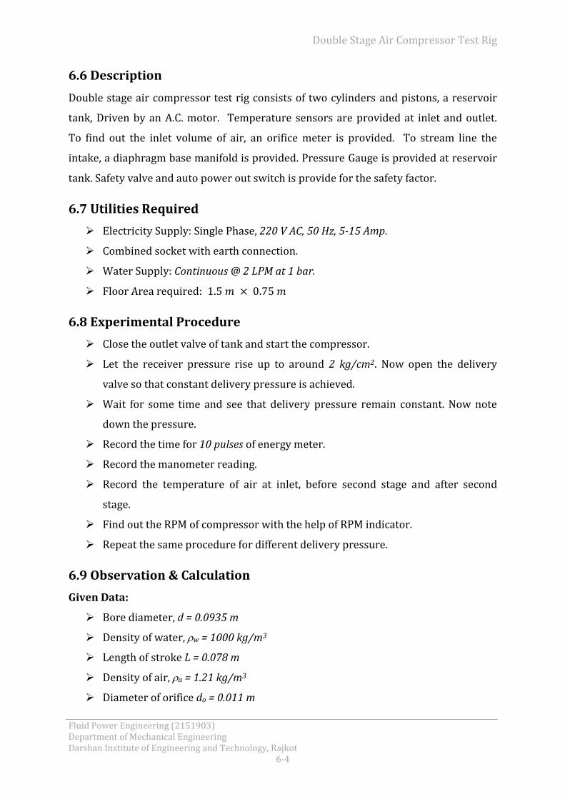
6.6 Description
Double stage air compressor test rig consists of two cylinders and pistons, a reservoir
tank, Driven by an A.C. motor. Temperature sensors are provided at inlet and outlet.
To find out the inlet volume of air, an orifice meter is provided. To stream line the
intake, a diaphragm base manifold is provided. Pressure Gauge is provided at reservoir
tank. Safety valve and auto power out switch is provide for the safety factor.
6.7 Utilities Required
Electricity Supply: Single Phase, 220 V AC, 50 Hz, 5-15 Amp.
Combined socket with earth connection.
Water Supply: Continuous @ 2 LPM at 1 bar.
Floor Area required:
6.8 Experimental Procedure
Close the outlet valve of tank and start the compressor.
Let the receiver pressure rise up to around 2 kg/cm2. Now open the delivery
valve so that constant delivery pressure is achieved.
Wait for some time and see that delivery pressure remain constant. Now note
down the pressure.
Record the time for 10 pulses of energy meter.
Record the manometer reading.
Record the temperature of air at inlet, before second stage and after second
stage.
Find out the RPM of compressor with the help of RPM indicator.
Repeat the same procedure for different delivery pressure.
6.9 Observation & Calculation
Given Data:
Bore diameter, d = 0.0935 m
Density of water, w = 1000 kg/m3
Length of stroke L = 0.078 m
Density of air, a = 1.21 kg/m3
Diameter of orifice do = 0.011 m
Double Stage Air Compressor Test Rig
Fluid Power Engineering (2151903) Department of Mechanical Engineering Darshan Institute of Engineering and Technology, Rajkot
6- 5
Co-efficient of discharge of orifice, Cd = 0.64
Diameter of pipe dP = 0.022 m
Energy meter constant, EMC = 3200 pulses / kW-hr
Atmospheric pressure Pa = ⁄
RPM of motor, Nm = 1440
Radius of swinging Field Dynamometer, R = 0.173 m
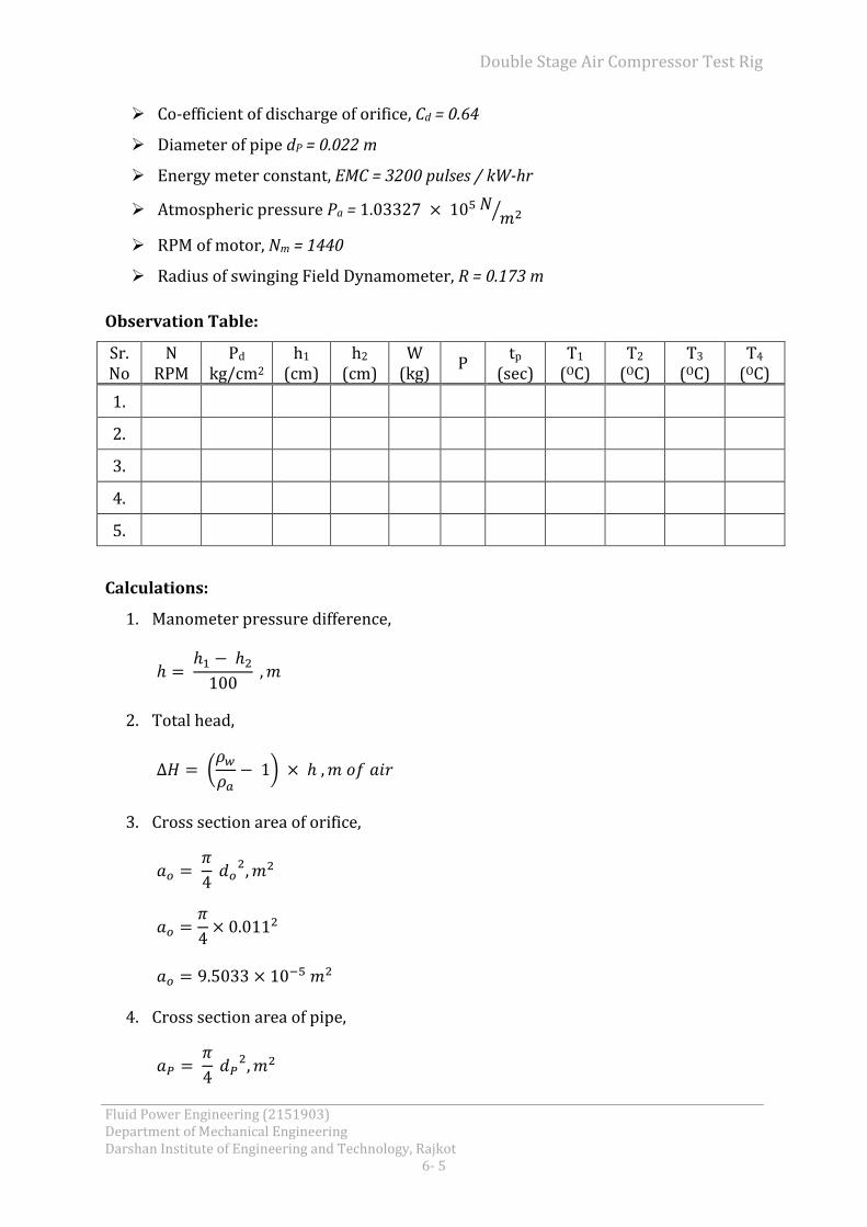
Observation Table:
Sr. No
N RPM
Pd kg/cm2
h1 (cm)
h2 (cm)
W (kg)
P tp
(sec) T1
(OC) T2
(OC) T3
(OC) T4
(OC)
1.
2.
3.
4.
5.
Calculations:
1. Manometer pressure difference,
2. Total head,
( )
3. Cross section area of orifice,
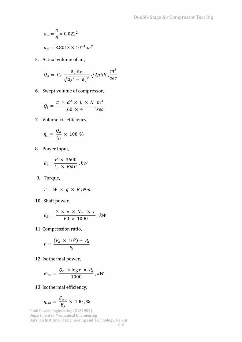
4. Cross section area of pipe,
Double Stage Air Compressor Test Rig
Fluid Power Engineering (2151903) Department of Mechanical Engineering Darshan Institute of Engineering and Technology, Rajkot
6-6
5. Actual volume of air,
√ √
6. Swept volume of compressor,
7. Volumetric efficiency,
8. Power input,
9. Torque,
10. Shaft power,
11. Compression ratio,
(
)
12. Isothermal power,
13. Isothermal efficiency,
Double Stage Air Compressor Test Rig
Fluid Power Engineering (2151903) Department of Mechanical Engineering Darshan Institute of Engineering and Technology, Rajkot
6- 7
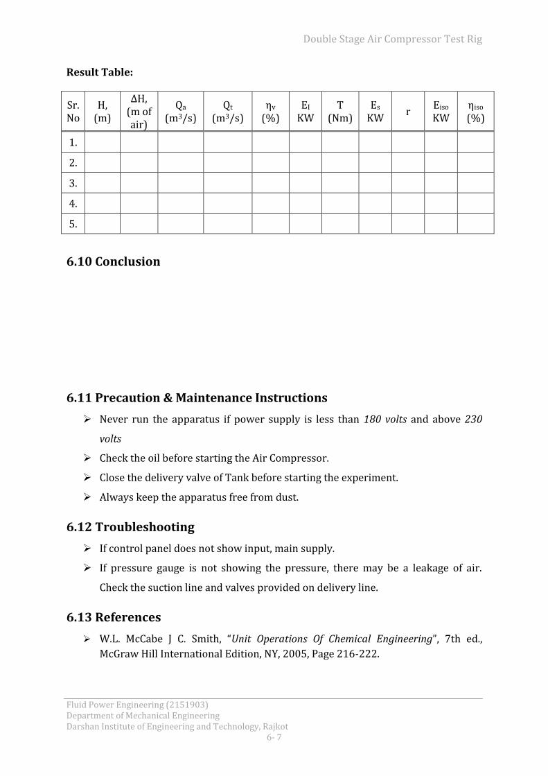
Result Table:
Sr. No
H, (m)
∆H, (m of air)
Qa (m3/s)
Qt (m3/s)
ηv (%)
EI
KW T
(Nm) Es
KW r
Eiso
KW ηiso (%)
1.
2.
3.
4.
5.
6.10 Conclusion
6.11 Precaution & Maintenance Instructions
Never run the apparatus if power supply is less than 180 volts and above 230
volts
Check the oil before starting the Air Compressor.
Close the delivery valve of Tank before starting the experiment.
Always keep the apparatus free from dust.
6.12 Troubleshooting
If control panel does not show input, main supply.
If pressure gauge is not showing the pressure, there may be a leakage of air.
Check the suction line and valves provided on delivery line.
6.13 References
W.L. McCabe J C. Smith, “Unit Operations Of Chemical Engineering”, 7th ed.,
McGraw Hill International Edition, NY, 2005, Page 216-222.