Embed Size (px)
Citation preview

FLOWPULSE
Instruction Manual


FLOW PULSE (SECOND EDITION REV 1)
November 2017
Part Number M-560-0-002-1P
COPYRIGHT
© Pulsar Process Measurement Limited, 2012-17. All rights reserved. No part of this publication may
be reproduced, transmitted, transcribed, stored in a retrieval system, or translated into any language in
any form without the written permission of Pulsar Process Measurement Limited.
WARRANTY AND LIABILITY
Pulsar Process Measurement Limited guarantee for a period of 2 years from the date of delivery that it will either exchange or repair any part of this product returned to Pulsar Process Measurement
Limited if it is found to be defective in material or workmanship, subject to the defect not being due to
unfair wear and tear, misuse, modification or alteration, accident, misapplication or negligence.
DISCLAIMER
Pulsar Process Measurement Limited gives nor implies any process guarantee for this product, and shall have no liability in respect of any loss, injury or damage whatsoever arising out of the
application or use of any product or circuit described herein.
Every effort has been made to ensure accuracy of this documentation, but Pulsar Process
Measurement Limited cannot be held liable for any errors.
Pulsar Process Measurement Limited operates a policy of constant development and improvement and
reserves the right to amend technical details as necessary.
TECHNICAL ENQUIRIES
Please contact Pulsar Process Measurement Limited for technical support.
COMMENTS AND SUGGESTIONS
If you have any comments or suggestions about this product, then please contact:
Pulsar Process Measurement Limited
Pulsar Process Measurement Inc.
Cardinal Building
Enigma Commercial Centre Sandy’s Road
Malvern
Worcestershire WR14 1JJ
United Kingdom
PO Box 5177
Niceville
FL 32578-5177
USA
Tel: + 44 (0) 1684 891371
Fax: + 44 (0) 1684 575985
Tel: + 1 850 279 4882
Fax: + 1 850 279 4886
Web Site: http://www.pulsar-pm.com
e-mail: [email protected] (general
information)
e-mail: support@ pulsar-pm.com (product support)
Web Site: http://www.pulsar-pm.com
e-mail: [email protected] (general
information)
e-mail: support.usa@ pulsar-pm.com (product support)


Contents
Chapter 1 Introduction.......................................................................................................................................... 1 About this Manual ................................................................................................................................................... 1
Additional Information ................................................................................................................................... 1 About the Flow Pulse ................................................................................................................................................... 2 Functional Description ............................................................................................................................................ 3 Product Specification .............................................................................................................................................. 4 EU Declaration of Conformity ............................................................................................................................... 6
Chapter 2 Installation............................................................................................................................................ 7 Unpacking ................................................................................................................................................................ 7 Power Supply Requirements .................................................................................................................................. 7 Cable Screen and Earth Requirement ..................................................................................................................... 7 Dimensions .............................................................................................................................................................. 8 Terminal Connection Details .................................................................................................................................. 8
Terminal Connections ..................................................................................................................................... 9 Power ............................................................................................................................................................. 10 Relay Output ................................................................................................................................................. 10 Current Output .............................................................................................................................................. 10 RS232 Serial Interface .................................................................................................................................. 10 RS485 Serial Interface with Modbus ........................................................................................................... 10
Flow Pulse Installation Procedures ............................................................................................................................ 11 Flow Pulse PC Installation ......................................................................................................................................... 12 Preparation for Operation ...................................................................................................................................... 12 Maintenance .......................................................................................................................................................... 13
Chapter 3 Setting-Up Flow Pulse ........................................................................................................................... 14 Interface ................................................................................................................................................................. 14 Using FlowPulse PC ............................................................................................................................................. 14
Pipe Internal Diameter .................................................................................................................................. 14 Flow Tab ................................................................................................................................................................ 17
Signal Strength .............................................................................................................................................. 17 Stability .......................................................................................................................................................... 18
Flow Record Tab ................................................................................................................................................... 18 Trace Tab ............................................................................................................................................................... 19 Parameters Tab ...................................................................................................................................................... 20
Pipe Internal Diameter .................................................................................................................................. 21 Calibration Factor .......................................................................................................................................... 21 Sensitivity ...................................................................................................................................................... 21 Damping ........................................................................................................................................................ 22 Volumetric Unit and Time Unit ................................................................................................................... 23 Access Level ................................................................................................................................................. 23 Step Response ............................................................................................................................................... 24 Step Response Threshold.............................................................................................................................. 24 Step Change Limit ........................................................................................................................................ 24 Flow Low and Flow High ............................................................................................................................ 24 mA Output ..................................................................................................................................................... 25 mA Output: mA Trim .................................................................................................................................. 26 Relay/Alarm .................................................................................................................................................. 27 RS-485 ........................................................................................................................................................... 28
Manual Setting....................................................................................................................................................... 29 Setup Menu ............................................................................................................................................................ 30 System Menu ......................................................................................................................................................... 30

Tools Menu ............................................................................................................................................................ 31 About Flow Pulse Menu ............................................................................................................................................ 31
Chapter 4 RS 485 Parameter Guide ..................................................................................................................... 32 Parameter System .................................................................................................................................................. 32 Parameter Access .................................................................................................................................................. 32 Output Parameters ................................................................................................................................................. 33
Flow Rate (P20 and P21) .............................................................................................................................. 33 Signal Strength (P22) .................................................................................................................................... 33 Stability (P23)................................................................................................................................................ 33
Configuration Parameters ..................................................................................................................................... 34 RS485 Communication and Modbus ........................................................................................................... 34 RS232 Communication ................................................................................................................................ 35 Processing Parameters .................................................................................................................................. 36 mA Output Parameters ................................................................................................................................. 38 Alarm/Relay Parameters ............................................................................................................................... 41 Flow Unit Parameters ................................................................................................................................... 43 Device Information Parameters .................................................................................................................... 44 Device Control Parameters ........................................................................................................................... 45
Chapter 5 Optimisation and Diagnostic ............................................................................................................... 47 Interpreting Diagnostic Trace ............................................................................................................................... 47 PC-over-RS485 ..................................................................................................................................................... 48 Quick-Response Setup .......................................................................................................................................... 49 Simulated Flow...................................................................................................................................................... 50 Saving & Loading Device Parameters ................................................................................................................. 50 Firmware Upgrade ................................................................................................................................................ 51 High Noise Environment ...................................................................................................................................... 52
Chapter 6 Common Questions and Answers ....................................................................................................... 53 Will mechanical vibration affect flow measurement? ................................................................................. 53 Is it possible to operate Flow Pulse in a high noise environment? ................................................................... 53 What is the effect of poor pipe condition? ................................................................................................... 53 What is the effect of pipe lining? .................................................................................................................. 53 Does Flow Pulse measurement drift over time? ............................................................................................... 53 Can Flow Pulse be operated in a wet environment? ......................................................................................... 53
Chapter 7 Troubleshooting.................................................................................................................................... 55 LED Indication ...................................................................................................................................................... 55 Fault Registers and Log File ................................................................................................................................. 55 Flow measurement is significantly different from expectation ........................................................................... 56 Flow reading under no-flow condition ................................................................................................................. 57 Flow reading fluctuates or erratic ......................................................................................................................... 58 No flow indicated under flow-condition .............................................................................................................. 58 Relay state not stable ............................................................................................................................................. 58
Appendix: Parameter Record ................................................................................................................................. 59

Page 1
Chapter 1 Introduction
Congratulations on your purchase of a Pulsar Flow Pulse. This quality
system has been developed over many years and represents the latest in non-
invasive ultrasonic flow monitoring.
It has been designed to give you years of trouble free performance, and a
few minutes spent reading this operating manual will ensure that your
installation is as simple as possible.
About this Manual
It is important that this manual is referred to for correct installation
and operation.
Additional Information
Additional Information
At various parts of the manual, you will find sections
like this that explain specific items in more detail.

Page 2
About the Flow Pulse
The Flow Pulse is an ultrasonic non-invasive flow monitor designed for use
on most industrial liquid flow applications. Flow Pulse uses a novel spread
spectrum analysis technique never before used in flow monitoring. It
introduces a radical new Digital Signal Processing approach for exceptional
repeatability.
Ultrasound is fired through the pipe wall at 90 degrees to the flow via a
tangentially mounted high-output ceramic, then refracted at angles across
the axis of the flow and subsequently reflected from bubbles, particles and
vortices in all directions and at a wide range of frequencies. The wide,
refracted, ultrasonic beam maximises the ultrasound energy captured from
flowing particles. These multiple reflections are received back into the unit
via a second crystal.
The mass of data generated is analysed using Flow Pulse’s Refracted Spread
Spectrum Analysis (RSSA) digital signal processing platform to derive flow
information. RSSA analyses and integrates the received signals over a wide
frequency range, then uses them for real-time analysis and flow rate
calculation.
Flow Pulse operates in a flow range from as little as 0.3m/s through to
4m/s, with a minimum particle size of 100µ and concentration of 200ppm
(the equivalent of hard water) or above.

Page 3
Functional Description
The Flow Pulse injects an ultrasonic signal through the pipe, and analyses the
returned signal in real-time to extract flow information. This provides
robust and repeatable flow monitoring using a scalable 4 to 20 mA output
and a volt-free relay switch. Interface with the PC over both the RS-485 and
RS-232 serial port is fully supported by the FlowPulse PC software, which
can be used for setting up and operating the device.
In addition, there is a RS-485 with Modbus RTU communication protocol
that interfaces Flow Pulse to Pulsar’s optional controllers which are listed
below:
• Flow Monitor wall mount unit
• Quantum 3
• Ultimate Controller
For further details on how to connect and use the Flow Pulse with the
controllers listed above, please refer to their individual instruction manuals,
which can be downloaded from our website:
https://www.pulsar-pm.com/support/downloads/manuals.aspx
For the best results, Flow Pulse should be applied where:
• There is full pipe flow
• The pipe material is steel, cast iron, ductile iron, plastic or glass, but
not rubber or flexible plastic pipes
• The pipe diameter is greater than 30 mm
• The pipe wall thickness is less than 20 mm
• The solids concentration in the fluid is greater than 200 ppm (e.g.
hard tap water), and typical particle sizes are larger than 100
microns
• There is no significant build-up within the pipe

Page 4
Product Specification
Physical Outside dimensions 120 x 65 x 65 mm (4.75 x 2.6 x 2.6 inch) Weight Nominal 1.5 kg (3.3lbs) Enclosure material/description Type 316 stainless steel casting Cable entry detail 1 cable entry M20 x 1.5mm gland Maximum separation 500 m (1,640 ft.)
Environmental IP Rating (Wall) IP68 Max. & min. temperature (electronics) -20 ºC to +70 ºC (-4oF to 158oF)
CE approval See EU Declaration of Conformity
Performance Accuracy/Repeatability ±5% typical subject to installation and pipe
conditions Resolution 3mm/sec. Pipe wall thickness Metal or rigid pipe up to 20mm (0.8in) thick Min. Particle size >100µ Max. particle size >200ppm Pipe diameter V1 = 30mm to 350mm (1.2 to 14in), V2 =
30mm to 1250mm (1.2 to 49.2in)
Min. range 0.3m/sec. Max. range (flow) 4.0m/sec. (10m/sec. for high flow version) Response time fully adjustable (1 sec. minimum for fast
response version)
Signal Processing Description RSSA (Refractive Spread Spectrum
Analysis)
Outputs
Analogue output 4-20 mA into a 1k load (when supply voltage is 22 VDC or greater) with 20µA resolution and user programmable span.
Digital output Full Duplex RS232 to PC software, Half Duplex RS485 to PC software, Half Duplex RS485 with Modbus RTU
Volt free contacts, number and rating 1 form "C" (SPDT) rated at 1A at 24VDC
Programming PC programming via RS232 or RS485 using FlowPulse PC Programmed data integrity Via non-volatile RAM
Supply Power supply 18 - 28V DC Power Consumption 2.4W @ 24V typical, 3W @24V maximum
Pulsar Process Measurement Limited operates a policy of constant development and improvement and reserve the right to amend technical details as necessary.

Page 5

Page 6
EU Declaration of Conformity

Page 7
Chapter 2 Installation
Unpacking
Power Supply Requirements
The Flow Pulse requires a DC 18-28V power supply. The typical power
consumption is 2.5W and the maximum power consumption should not exceed
3W. The power supply should also be correctly fused at 250mA.
Care should be exercised when connecting the power supply by ensuring the
correct terminals and voltage rating are used to avoid damaging the device.
Cable Screen and Earth Requirement
A screened multi-core cable should be used (minimum conductor size of 0.5mm².
The cable screen should be connected to the enclosure at the cable entry point via
the cable gland, see figure below. The screen of the cable should be earthed at the
other end. The supplied cable gland is suitable for cables up to 10mm O.D.
Important Information
All shipping cartons should be opened carefully. When using a box cutter,
do not plunge the blade deeply into the box, as it could potentially cut or
scratch equipment components. Carefully remove equipment from each
carton, checking it against the packing list before discarding any packing
material. If there is any shortage or obvious shipping damage to the
equipment, report it immediately to Pulsar Process Measurement Limited.

Page 8
If using RS485 then connect terminal 8 (RS485 SCR) to the Modbus return.
The power supply ground on Flow Pulse must not be earthed or connected to the
cable screen.
Dimensions
Cable Entry
It is recommended that you use the cable gland that comes with the Flow
Pulse to ensure that the ingress rating is maintained.
Terminal Connection Details

Page 9
FlowPulse IP68
The Flow Pulse IP68 has an integral 10-core screened cable fitted and is
fully encapsulated.
Wiring
The IP68 version of the Flow Pulse is designed to work with Pulsar’s Flow
Monitor wall unit, utilising the RS485. But it is also available on its own for
connection to existing Modbus or other devices to monitor RS485, mA
output and/or relay behaviour.
Below is a table identifying the terminal connections for each cable:
Description Wire colour FlowPulse
Terminal No. Flow Monitor Terminal No.
0V (GND) Blue 1 22
24V DC Brown 2 23
NC (Relay) Red 3 Not used with Flow Monitor
COM (Relay) Black 4 Not used with Flow Monitor
NO (Relay) Violet 5 Not used with Flow Monitor
mA OUT (-) White 6 Not used with Flow Monitor
mA OUT (+) Pink 7 Not used with Flow Monitor
RS485 screen Green 8 21
RS485 + Yellow 10
24
RS485 - Grey 9 25
Cable Screen Green &
Yellow
Not connected
in FlowPulse 3
Important Information
DO NOT TRY AND REMOVE THE LID. Consult Pulsar if you
require any assistance with the device.

Page 10
Terminal Connections
Power
Flow Pulse operates from DC power supply or batteries within the range of 18
to 28 VDC. When using a long cable (in excess of 100 m), please ensure that
the minimum supply voltage is at least 22 VDC for the Relay to operate reliably.
Relay Output
The relay can be programmed for a variety of alarms. The relay contacts on
the Flow Pulses are rated at 1A at 24V DC. All connections should be such
that the short circuit capacity of the circuits to which they are connected, is
limited by fuses rated so that they do not exceed the relay rating.
The N.O. terminal is normally open while the N.C. terminal is a normally
closed circuit to the common terminal.
Current Output
There is one mA output, of 4 - 20mA with a maximum load of 1k. It has a
20 µA resolution and a user programmable and adjustable span.
RS232 Serial Interface
The RS232 interface is available on the RJ-11 socket for setting up and
operating the Flow Pulse using the FlowPulse PC software.
It is recommended that the serial cable does not exceed 10 metres in length.
RS485 Serial Interface with Modbus
It is recommended that a screened cable is used, and the cable screen is
connected to the screen terminal of the RS485 terminals. If RS485
connection is not required, the cable screen should be connected to the metal
enclosure of Flow Pulse at the cable entry point and earthed at the other end
of the cable.
The RS485 terminals are galvanically isolated.
Please ensure that the termination switch is set to the “ON” position if
termination is required.
The RS485 serial port can either be used with the Modbus RTU protocol or
to interface with FlowPulse PC.

Page 11
Flow Pulse Installation Procedures
All electronic products are susceptible to electrostatic shock, so follow
proper grounding procedures during installation.
• Before installation, ensure that the necessary cabling has been fitted and
that the device is not being powered.
• Flow Pulse must be mounted on the external, dry surface of the pipe.
The device should not be submerged in liquid.
• Flow Pulse and the pipe surface around the installation location should
not be exposed to external flowing liquid.
• Flow Pulse should be installed on a straight section of pipe at least 5 pipe
diameters from any restrictions or sources of fluid turbulence (e.g.
pumps, valves, tees, elbows) where possible.
• On horizontal pipes, it is preferable to mount Flow Pulse between
1 o’clock and 5 o’clock position on the pipe to avoid air pocket on top or
sedimentation on the bottom, as illustrated in Figure 2:
Figure 2: Recommended positioning on horizontal pipes
• Ensure that both the base of the Flow Pulse and the pipe surface are free
from debris. Pipes with flaking paint should be cleaned down.
• Apply silicone grease or silicone pad to the base of Flow Pulse. Silicone
pad is recommended where vibration and heat are frequently
encountered.

Page 12
• Flow Pulse should be strapped onto the pipe with the supplied metal
banding. If further installation attempts are made, reapply silicone
grease. In the case of silicone pad, ensure that the pad surface is clean
from debris, the pad is in good condition, and there is no folding that
might cause uneven contact with the pipe.
• Ensure that the Flow Pulse is aligned along the pipe axis, as illustrated in
Figure 3:
Figure 3: Flow Pulse correctly aligned along the pipe axis.
• Tighten the banding while ensuring best contact and correct alignment
between the Flow Pulse and the pipe.
Flow Pulse PC Installation
The FlowPulse PC software is supported on Win 7, Win 8 and Win 10 (32
and 64 bit). The .Net Framework 4.0 is required to run the program. This is
free for download online.
Run Setup.exe if downloaded from the Pulsar website (https://www.pulsar-
pm.com/support/downloads/software.aspx) to install the FlowPulse PC
software. Or alternatively, if you are installing from the CD provided please
select to install FlowPulse PC software from the options on screen. A
FlowPulse PC shortcut icon will then be created on the Desktop. Double
click on the shortcut icon to launch the program.
Preparation for Operation
Before applying power, check the following:
Flow Pulse is mounted correctly with optimum acoustic coupling between the
base and the pipe surface.
The power supply is correctly connected at the terminal block.
There is no exposed or loose wiring around the connection terminals.
FlowPulseFlowPulse

Page 13
• Remove the lid, and apply power to the Flow Pulse.
• The RED led will flash for 6 seconds, then the GREEN led will begin to
flash. The flashing of the GREEN led indicates that the device is
operational.
• Connect the relevant serial cable and converter to the PC depending on
whether RS232 or RS485 is being used.
• Launch the FlowPulse PC program. If using PC-over-RS485, change
baud rate to 19200 using Setup->Serial Port, default is 57600 over
RS232. Click the “Tick” icon to connect.
• When connection is established, the current parameters stored on the
Flow Pulse will be extracted by FlowPulse PC. The “Device” bulb on the
top right corner of the program will light up to indicate a successful
connection.
• Choose the “Parameters” tab on FlowPulse PC, where the current device
parameters are shown and can be modified. (please refer to the Chapter
on Setting Up Flow Pulse before modification)
• On the top left corner of the “Parameters” tab, set the Pipe I.D. field to
the pipe’s internal diameter in units of either millimetres (default) or
inches.
• Click on the “SAVE” button.
• Return to the “Flow” tab to monitor flow.
Please refer to the Setting Up Flow Pulse chapter for more information.
Maintenance
There are no user serviceable parts inside Flow Pulse. If you experience any
problems with the unit, then please contact Pulsar Process Measurement for
advice.
To clean the equipment, wipe with a damp cloth. Do not use any solvents on
the enclosure.
When relocating, or reinstalling the Flow Pulse, please ensure that the pipe
internal diameter value stored on the device is updated accordingly.

Page 14
Chapter 3 Setting-Up Flow Pulse
Interface
The default method for interfacing with Flow Pulse is by using the supplied
Flow Pulse PC software and serial cable.
If the optional the Flow Monitor is installed, common setup parameters can
be programmed directly from the Monitor. Please refer to the Flow Monitor
user manual for more information.
Programmed parameters are stored in Flow Pulses non-volatile memory and
are therefore retained after power-off.
Using FlowPulse PC
After launching the program and connecting to the Flow Pulse, the device
parameters will be automatically extracted once a connection is established.
Refer to the section on “Preparation for Operation” in Chapter 2 for more
details on FlowPulse PC installation and how to connect to Flow Pulse.
Pipe Internal Diameter
The pipe internal diameter is the only parameter that must be entered to get
the Flow Pulse working to measure the flow.
Choose “Parameters” tab, enter the pipe internal diameter in units of mm in
the “Pipe I.D.” field, then click the “SAVE” button.
Return to the “Flow” tab to monitor flow, the “Record” tab shows a
time-plot of flow.
Figure 4 shows the main window of the FlowPulse PC software:

Page 15
Figure 4: The flow information window of FlowPulse PC.
Connect: click to attempt connection to the Flow
Pulse device.
• Set the baud rate to 57600 (Setup>Serial Port) with
RS232 or to 19200 with RS485
Disconnect: appears after connection is established.
Click to disconnect from the Flow Pulse.
Diagnostic Trace: requests for diagnostic trace.
• When active, this icon border will light up yellow
and ‘live’ traces can be observed on the “Trace”
tab.
• Click again to deactivate.
•

Page 16
Save Data to File: click to record data from Flow
Pulse.
When activate, this icon will light up yellow. Click
again to deactivate.
• In order to record diagnostic traces along with the
flow data, please ensure that the trace icon is active
and live traces are shown on the Trace tab.
• The recording interval is set via the Setup-
>Recording Interval menu. The default is one record
in every 2 seconds.
• As of FlowPulse PC 1.2.4, if the Flow Pulse does not
have a site name, a site name will be requested.
FlowPulse PC 1.2.3 and lower do not require a site
name.
• A .flg file is then generated, named with the
“FlowPulse-” prefix followed by the site name and
the current date & time stamp. An example is
“FlowPulse-Site1234-12-7-2012-08-00.flg”. This
can be renamed. FlowPulse PC 1.2.3 and older
generates a .txt file with the same naming structure,
minus the site name, this cannot be renamed.
• If recording over a long duration, a new file will be
automatically generated after 30 minutes.
• The recorded data files are stored on the FlowPulse
PC installation folder by default.
• To stop recording, click the ‘Save Data’ button again
Replay recorded data: click to replay recorded data.
This can be performed without connection to a Flow
Pulse.
• The program will disconnect from a Flow Pulse
during replay.
• A prompt will appear for choosing the data files to
play.
• Select the data files to replay, ensure that only
FlowPulse PC recorded data files are selected.
• To replay more than one file, select multiple files by
holding down the CTRL key on the keyboard while
clicking additional files.
• Recorded traces are shown in the Trace tab and the
recorded flow is shown in the Flow tab.
• During replay, click again to stop.

Page 17
Chart a Log File: click to chart a log file. By
charting a log file, the whole log file will be drawn
out at once.
• The program will disconnect from a Flow Pulse
during charting.
• A prompt will appear for choosing the log file to
play.
• If the log file is longer than the length of the ‘Flow
Record’ chart, FlowPulse PC will prompt you to
continue to the next section of logged data.
Increase Replay Speed: during replay click to
increase replay speed.
Decrease Replay Speed: during replay click to
decrease replay speed.
Exit: click to exit program
Flow Tab
The default screen of FlowPulse PC is the Flow tab. The dial on the left
displays the linear flow velocity, while the numerical display on the right
shows the volumetric flow rate. The default volumetric unit is litres per
second, and is configurable on the Parameters tab.
Signal Strength
The signal strength gives an indication of the strength of the flow signal
detected. A signal strength level of higher than 60% is recommended for
reliable operation. A higher Sensitivity setting may improve the Signal
Strength (please refer to the Sensitivity section before changing).

Page 18
Stability
The stability level is an indication of the consistency of flow reading, as
derived from the combination of signal strength and statistical fluctuations
of the flow reading. A high level of stability would point to a low-noise
environment, clean and optimum acoustic pipe conditions, and a relatively
laminar liquid flow within the pipe. However, the stability level does not
necessarily indicate the accuracy of the flow reading as this is subject to
calibration. A higher stability level indicates higher level of repeatability
and better flow-tracking.
Flow Record Tab
The Flow Record provides a record of flow over time. Each point of flow on
the graph represents a 1.2 second interval. However, when the trace button
has been pressed and a trace is being retrieved from the Flow Pulse this
slows down how frequently a point on the graph is plotted and the points
then represent a 2 second interval.
You can zoom in by clicking and holding the mouse then selecting the
region to zoom in on. Zoom out by right clicking on the chart and selecting
“Undo All Zoom”.
To clear the Flow Record chart, select Setup->Clear Flow Record Chart
menu while the chart is inactive.

Page 19
Trace Tab
This calls and displays diagnostic traces when the Trace button is activated.
Please refer to Diagnostic and Troubleshooting for more information on
interpreting the traces.
Note
When the save data to file function is being used, flow information and
traces will be written to file at the fixed interval selected via Setup-
>Recording Interval. (See Record to file function in “Using FlowPulse
PC”.

Page 20
Parameters Tab
This enables the user to setup the Flow Pulse. It is important to note the
following to ensure that Flow Pulse is correctly programmed:
At every connection to Flow Pulse, FlowPulse PC will synchronise the
values on the Parameter tab to that stored on Flow Pulse.
After changing any parameter, the “SAVE” button must be clicked to send
and save the new values to the device.
The values need to be valid and within allowed range for a parameter
change to be successful.
If the change is not successful, the values shown on the Parameter tab will
reflect the current parameter value on Flow Pulse.
If Flow Pulse is being controlled simultaneously on both RS232 via
FlowPulse PC and RS485 via Modbus interface, the values on the Parameter
tab will not be instantly updated on FlowPulse PC if a parameter change is
instructed via the RS485 Modbus.

Page 21
Pipe Internal Diameter
The pipe internal diameter is the only parameter that must be entered after
every Flow Pulse installation.
The default unit is millimetres (mm), with the option for unit of inches.
Calibration Factor
The calibration factor can be used to internally scale the flow reading by a
multiplication factor.
As an example a factor of 0.5 will scale the reading to give only half of its
original value, or a factor of 1.2 will scale the reading to give 120% of its
original.
This is set to 1.0 by default, implying no scaling. Note that any change in
the calibration factor is stored on Flow Pulse.
Sensitivity
The sensitivity of Flow Pulse can be increased for difficult pipes or liquids.
When using Flow Pulse on high sensitivity setting, observations should be
made to ensure that no-flow indication is consistent. Operating at higher
sensitivity may increase the susceptibility of the device to external sources
of noise.
A lower sensitivity may be desirable when operating in an environment that
has the potential for electrical interference. At lower sensitivities,
observations need to be made to ensure that there is sufficient signal
strength for reliable detection of flow. This needs to allow for any long-
term variation in pump or pipe conditions. In general, minimum signal
strength of 60% is required.

Page 22
It is recommended that the sensitivity be set as high as possible subject to
the constraint of false flow indication under no-flow condition.
High Sensitivity
• Good for low flow or poor
pipe condition with weak
signal strength.
• If set very high, watch for
false indication of flow
when the pump is not
running and there is no
flow. This may not be
critical in applications
where the main alarm
condition is for low or no
flow while pumping is
called for.
Low Sensitivity
• Good for high flow or
excellent pipe condition
with strong signal strength.
• If set very low, watch for
false indication of no flow
when the pump is running
and there is flow. It is
recommended that the
sensitivity be set as high as
possible subject to the
constraint of false flow
indication.
Damping
Fluctuations from non-laminar flow as well as from electrical noise will
affect the stability of the flow readings. The damping parameter allows
these fluctuations to be smoothed, at the expense of response time.
A higher damping will produce a more stable reading with less fluctuation,
but the response time to a sudden change of flow is longer, and vice versa.
Note that a “Step Response” feature allows a large change of flow to by-
pass damping, potentially giving a faster response at the start and end of
pumping cycles. Please refer to the Step Response section for more details.
By default, the damping is set to give a stable reading, and the response time
is in the region of 30 seconds.

Page 23
Volumetric Unit and Time Unit
The flow measurement on the Flow Pulse is performed in terms of
volumetric flow rate.
The defaults are litres for the volumetric unit and seconds for the time unit,
giving flow rate in units of litres per second.
This can be modified to give the desired units of flow rate. Please note that
both volumetric and time units should be selected such that the numerical
range falls within 0.01 to 60000 for the corresponding pipe internal
diameter.
The table below lists the valid combination of volumetric and time units:
Valid Volume Per Time
Litres • Second
• Minute
Cubic Metres • Minute
• Hour
Cubic Feet • Second
• Minute
Imperial Gallons • Second
• Minute
US Gallons • Second
• Minute
Million US Gallons • Hour
• Day
Access Level
The access level refers to the permission to perform actions or modify some
parameters. There are two levels of access, the USER and SERVICE levels.
At power-up, the access level on Flow Pulse always defaults to USER.

Page 24
Step Response
The step response allows Flow Pulse to temporarily bypass damping and
track any sudden change in flow commonly encountered during the
beginning and end of a pumping cycles.
This function is on by default.
Step Response Threshold
The step response threshold is the change in flow required for the normal
damping to be bypassed. The range of the step response threshold is:
Min = 22, Max = 426 Default = 60
400 relates to the ‘Flow High’ value.
The higher the step response threshold, the larger the jump in flow needs to
be before damping is skipped.
Step Change Limit
The step change limit is the maximum change in flow that the Flow Pulse
will ignore the damping for. A change in flow greater than this limit will
adhere to the set damping.
Min = 22, Max = 426 Default = 119
Flow Low and Flow High
The “Flow Low” and “Flow High” parameters represent the minimum and
maximum flow rate setting, in units of volumetric flow rate.
By default, the flow rate limits, in units of litres per second, are set to
correspond to the specification of flow velocity range of 0 to 4 m/s (0 to
10m/s for high flow version)
Note that the mA output is scaled to the flow rate limits that are set here.
For example, if the range is set to Flow Low = 3 litres/sec and Flow High =
10 litres/sec, then the mA output will be 4 mA at 3 litres/sec and 20 mA at
10 litres/sec. Please refer to the “mA Output” section for more information.

Page 25
mA Output
mA Low, mA High, Flow Low, Flow High
The mA output has a range of 4 to 20 mA by default. This is scaled to the
flow range set by the Flow Low and Flow High parameters. The following
figure illustrates this:
Figure 5: mA output scaling versus the low-high range of flow.
The mA High limit must be larger than the mA Low limit, and the Flow
High limit must be larger than the Flow Low limit.
The Flow Low and Flow High limits are in units of volumetric flow rate as
determined by the volumetric and time unit parameters (litres/sec by
default). Therefore, the Pipe I.D. should be correctly set before setting the
Flow Low and High limits.
mA Output
FlowFlow Low limit Flow High limit
mA High limit
(def: 20mA)
mA Low limit
(def: 4mA)

Page 26
As an example, in an application with low flow through a 100 mm Pipe I.D.,
the user can choose to scale the mA output from 4 to 20 to correspond to a
flow range of 0 to 15 litres/sec instead of the full flow range of 0 to 31
litres/sec. This is achieved by first ensuring that the Pipe I.D. has been
correctly set, and then setting the Flow High limit to 15 (the Flow Low limit
is 0 by default).
The mA Low and mA High setting can also be used to make small
adjustment to calibrate the device’s mA output at Flow Low limit and Flow
High limit. For example, if the mA output is 4.05 mA at Flow Low limit,
the mA Low setting can be set from 4.0 to 3.95 for calibrating the actual mA
output to 4.00 mA exactly.
mA Output: mA Trim
The mA trim allows calibration to the mA output by using a fixed mA
offset. The offset is in units of microamps (µA).
For example, if the mA output is 4.1 mA at Flow Low limit, an offset of
minus 100 µA can be entered. Entering and saving -100 (minus 100) to mA
Trim would produce 4.0 mA at Flow Low limit.
The maximum offset allowed is ±500 µA (±0.5 mA). The mA trim should
only be used to make small offset to the mA output. This offset is applied
across the full mA range.
Page 27
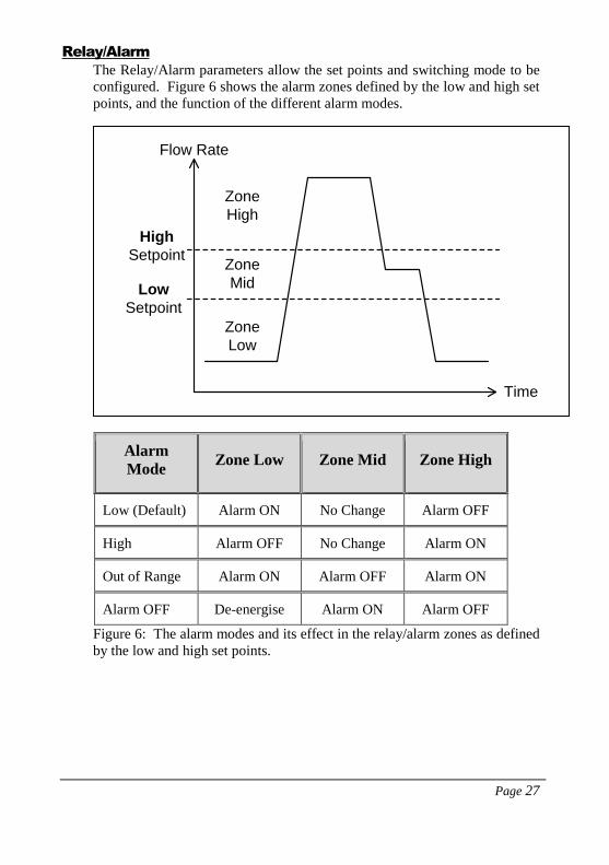
Relay/Alarm
The Relay/Alarm parameters allow the set points and switching mode to be
configured. Figure 6 shows the alarm zones defined by the low and high set
points, and the function of the different alarm modes.
Alarm
Mode Zone Low Zone Mid Zone High
Low (Default) Alarm ON No Change Alarm OFF
High Alarm OFF No Change Alarm ON
Out of Range Alarm ON Alarm OFF Alarm ON
Alarm OFF De-energise Alarm ON Alarm OFF
Figure 6: The alarm modes and its effect in the relay/alarm zones as defined
by the low and high set points.
Flow Rate
Time
High
Setpoint
Low
Setpoint
Zone
Low
Zone
Mid
Zone
High

Page 28
The default alarm mode is low alarm.
The default relay mode is normally de-energised. The connection to the NC
terminal is closed.
For low and high alarms, the Mid zone can be used as a buffer zone before
switching occurs.
The Relay parameter (P204) is used to set whether you wish the relay to de-
energise or energise in a state of alarm.
The Low and High Set-points are in units of volumetric flow rate as
determined by the volumetric and time unit parameters (litres/sec by
default). Therefore, the Pipe I.D. should be correctly set before setting the
Low and High Set-points.
Persistence is the number of continuous flow reading that must exceed the
relevant set points before the alarm/relay status is switched. The Low
Persist (LowPsis) parameter is associated with the Low Set-point while the
High Persist (HighPsis) parameter is associated with the High Set-point.
For example, at low alarm mode, the flow must exceed the High Set-point
before the alarm is disarmed and the relay switched. If the High Persist
value is set to 2, then there must be 2 consecutive flow readings that exceed
this set point before a switch is triggered.
RS-485
The Flow Pulse can be interfaced using Modbus via the RS485 terminals.
The default Modbus Slave ID is 126. The chapter on Parameter Guide
provides more details on Modbus register addresses and valid values.
The RS-485 port can also be used to interface with the FlowPulse PC
software, by selecting the PC-485 mode. Please ensure that you have a USB
to RS-485 converter before setting Flow Pulse to this mode, as this is
required for communicating with the device in the PC-485 mode. Refer to
the PC-over-RS485 section in Chapter 5.

Page 29
Manual Setting
There is an option for manually setting the parameters using the Manual
Setting terminal on the Parameter tab, as illustrated in the following figure.
Figure 7: The manual setting window on the Parameter tab.
Every parameter on Flow Pulse is identified by a unique Address, and the
content is the parameter Value.
All configurable parameters can be queried by entering the parameter
address in the Address field and clicking on the Query button. The Flow
Pulse will reply with the current value of the parameter.
For setting a parameter, both the Address and Value must be entered before
clicking on the Set button. The appropriate access levels are required for
setting parameters.
The list of parameter addresses and valid values are available in the chapter
on Parameter Guide.
The Manual Setting terminal should not be used for the normal setting up of
Flow Pulse. Refer to the “Parameter Guide” before setting parameters using
address-value pair.

Page 30
Setup Menu
This menu enables setting up of the RS232 port. The default setting when
interfacing using FlowPulse PC is 57600 Baud 8bits-No Parity-1Stop bit.
There is normally no need to change this as FlowPulse PC should
automatically detect a Flow Pulse connected however a specific comport can
be selected in the ‘Serial Port’ sub menu.
The ‘Recording Interval’ menu controls the time interval before a new flow
record and trace is saved to file when the save-to-feature is in use.
The ‘Clear Flow Record Chart’ option allows the Flow Record chart to be
cleared.
The ‘Work Folder’ allows the setting of a default folder for data files to be
saved.
System Menu
This menu provides the option to perform the following actions:
Save
Device
Parameters
Extract configuration parameters from the device and save
onto PC as a parameter file. This is saved to FlowPulse
PC’s installation folder and the filename is prefixed with
“ParamFlowPulse-”.
Load
Parameter
to Device
Load the parameters from a parameter file onto Flow Pulse.
This should only be used with a file that has a prefix of
“ParamFlowPulse-”
Bootloader
Control
Launch the Bootloader PC program for connecting to Flow
Pulse’s Bootloader. This allows the firmware on Flow
Pulse to be upgraded. Note that any customised parameters
will be erased during a firmware upgrade, and therefore it
is recommended that device parameters are saved onto PC
before performing a firmware upgrade.
Reset
Device
To Bootloader
Reset Flow Pulse into Bootloader mode. The Bootloader
PC program must be used to connect to Flow Pulse in this
mode. Flow Pulse will resume normal operation if no
connection is established within 30 seconds.
Parameter
Factory
Reset
This resets all parameters to factory default.

Page 31
Tools Menu
This menu is available in FlowPulse PC 1.2.4 and newer, it provides the
following actions:
Export Data
to CSV
This is used to convert a Flow Pulse log file to CSV format.
This provides a more readable format for the data that can
be viewed in programs such as Microsoft Excel and Google
Docs.
Chart Data
File
Plot the entire record of a log file. If the log file is longer
than the time frame on the window, a prompt will appear to
continue to the next time frame.
Modbus to
PC-485
Allows changing a Flow Pulse that is currently set to Modbus
to PC-485 so that FlowPulse PC can work with the Flow
Pulse. (This feature requires a Modbus to USB converter).
Write
Modbus
Register
This allows FlowPulse PC to act as a Modbus master and
modify single parameters on a Flow Pulse via Modbus. (This
feature requires a Modbus to USB converter).
About Flow Pulse Menu
This menu provides information on the current version of FlowPulse PC
program.
When connected to a Flow Pulse, information on the firmware and hardware
versions of the device are also available.

Page 32
Chapter 4 RS 485 Parameter Guide
Parameter System
Every parameter on the Flow Pulse is represented by a unique address and a
value. The parameters consist of two main types: output parameters and
configuration parameters.
Output parameters are read only and cannot be set by the user. Examples
are current flow reading and current signal strength.
Configuration parameters can be queried and set. With each parameter,
there is a factory default value, an associated access level which is required
for setting, and a valid range of values for each parameter.
The parameters are always stored and entered as whole numbers, and the
absolute range is from 0 to 65535, please refer to individual parameter for
individual range.
The naming syntax for the parameters is with a prefix of ‘p’ before the
address. For example, a parameter at address 102 is “P102”. The
value/content of the parameter is delimited by a colon “:”, such that
“P102:20” indicates that the parameter at address 102 has a value of 20.
The terms “parameter” and “register” are used interchangeably as the
parameter number is the actual address of the storage register.
Parameter Access
The parameters on the Flow Pulse can be accessed using any of these
methods:
a) The parameters tab on FlowPulse PC (RS232 or RS485)
b) The manual setting terminal on FlowPulse PC (RS232 or RS485)
c) Modbus communication protocol (RS485)
It is recommended that only one method of access is used at any point in
time.
Note: When using methods (b) or (c), the parameter guide in this chapter
should be referred to as the value required may be different from the values
normally entered on FlowPulse PC with method (a).

Page 33
Output Parameters
Flow Rate (P20 and P21)
The current flow rate can be read from register 20 and 21, in the following
format:
P20 contains the whole number part of the flow reading, while P21 contains
the fractional part of the flow reading. The p21 is stored as a whole number
from 0-999 (allowing a fractional representation from 0.001 to 0.999).
Signal Strength (P22)
P22 gives the current signal strength in terms of percentage, from 1 to 100.
Stability (P23)
P23 gives the current stability in terms of percentage, from 1 to 100.
12.36
Register [20] = 12 Register [21] = 360

Page 34
Configuration Parameters
RS485 Communication and Modbus
The default RS485 setting is 19200-8Bit-Noparity-1Stopbit.
P51 allows the Modbus protocol to be turned on and off, and P52 is the
Modbus Slave ID of the Flow Pulse.
When using Modbus-RTU, note that the register addressing scheme uses
Base-0 addressing protocol (i.e. there is no offset of 1)
Parameter Addr Options Def. Notes
Modbus
Mode 51
0 = Not in use
1 = RTU
2 = N/A
3 = PC-485
1
ASCII mode not fully
supported yet.
The PC-485 mode
enables FlowPulse PC
interface using
RS485. Modbus
protocol turned off
while using PC-485.
Refer to PC over 485
section in Chapter 5
for more information.
Device
Address 52 Unique Address,
1 - 127 126 Modbus device ID
Baud Rate 53
0 = 1200
1 = 2400
3 = 9600
4 = 19200
5 = 38400
6 = 57600
7 = 115200
4 Baud rate for RS 485.
Parity 54 0 = No parity
1 = Odd parity
2 = Even parity
0 Parity for RS 485
Stop Bit 55 1 – One stop bit
2 – Two stop bits 1 Stop bit for RS 485

Page 35
RS232 Communication
The default RS232 setting is 57600-8Bit-Noparity-1Stopbit.
Parameter Addr Options Def. Notes
Baud Rate 61
0 = 1200
1 = 2400
3 = 9600
4 = 19200
5 = 38400
6 = 57600
7 = 115200
6
Baud rate for RS 232
FlowPulse PC/debug
/reflash port.
Parity 62 0 = No parity
1 = Odd parity
2 = Even parity
0 Parity for RS 232
Stop Bit 63 1 – One stop bit
2 – Two stop
bits
1 Stop bit for RS 232

Page 36
Processing Parameters
The following are parameters that relate to the detection and processing of
the flow signal.
Parameter Addr Options Def. Notes
Magnitude
Threshold
(Sensitivity)
102 1200 - 3000 1600 A higher number gives
lower sensitivity.
Damping 104 10 - 40 24 A higher number gives
more damping.
Average Count 105 1 - 20 6
This is the number of
averaging to perform
on the reading – this is
independent of the
damping process.
Reducing this will
increase flow sampling
rate at the expense of
measurement stability.
Calibration Factor 108 1 - 500 100
The calibration factor
for flow reading in
percentage terms,
default is 100%. As
example, 50% would
half and 200% would
double.
Pipe Internal
Diameter 110 10 - 3000 15
Expected Pipe Internal
Diameter in units of
millimetres.
Noise Adapt
Threshold 111 500 - 3000 1000
Defines the difference
between the min value
of the trace and the
normal floor before a
trace is considered to
have a raised noise
floor.
Step Response
Mode 113
0 = Off
1 = On 1
When StepResp is off,
no damping by pass
will be performed.

Page 37
Parameter Addr Options Def. Notes
Step Response
Threshold 115 22 – 426 60
The threshold that the
step change size needs
to exceed before
damping by pass is
invoked.
May use diagnostic
trace to adjust this.
Minimum Flow
Cut-off 120 250 – 4000 740
This parameter
multiplies the units of
flow by 23 on the
horizontal axis of the
flow trace. E.g. if set to
2300, then the
corresponding flow
index would be 100,
and the FlowPulse will
not report any flow
unless the red(flow)
indicator exceeds 100
on the flow index.
Step Change
Limit 121 22 - 426 119
StepChangeLimit is the
limit on any sudden
change in flow reading.
May use diagnostic
trace to adjust this.
Track Threshold
Add 128 20 – 2000 400
Only activated when
the noise floor is raised,
such that the noise floor
is more than P111 away
from the normal floor
without flow. This
causes the flow to be
tracked at a lower flow
index so that
compensation can be
applied.

Page 38
Parameter Addr Options Def. Notes
Pipe Type 133 0 – 2 0
Adjustment factor to
compensate for the type
of pipe material:
0-Iron (No change)
1-Stainless Steel (x1.8)
2-Hard Plastic (x1.1)
Density 134 0 – 4 2
This parameter is sued
to set up the type of
material being
measured in the pipe:
0-Very Low (water
with no bubbles)
1-Low
2-Medium (Effluent)
3-High
4-Very High (Bubbly)
mA Output Parameters
The following are parameters that relate to the mA output and scaling to
flow measurement. Please refer to the diagrams in Chapter 3 –mA Output
sections before setting the parameters manually or over Modbus.
Parameter Addr Options Def. Notes
mA Low 162 3000 - 9000 4000
In units of µA
(1000=>1mA). This
can be used to adjust
the lower limit of the
mA output. Small
adjustment can also be
made to calibrate the
mA output.
mA High 163 10000 -
20000 20000
In units of µA
(1000=>1mA). This
can be used to adjust
the higher limit of the
mA output. Small
adjustment can also be
made to calibrate the
mA output.

Page 39
Parameter Addr Options Def. Notes
mA Trim 164 0 - 1000 500
In units of uA, applies
an offset across the full
range of mA output.
This is centred upon
500, such that the
default value of 500 = 0
offset. 400 would give
-100 µA offset, while
650 would give +150
µA offset. This differs
from the method of
directly entering -100
or +150 on the
FlowPulse PC
parameter tab.
Low mA Trim 170 0 - 2000 1000
In units of µA, it
applies an offset to the
lower end of the mA
output range. The
default value is 1000
which relates to 0 trim
added. Anything lower
than 1000 will subtract
from the mA output and
anything above 1000
will add to the output.
High mA Trim 171 0 – 2000 1000
In units of µA, it
applies an offset to the
higher end of the mA
output range. The
default value is 1000
which relates to 0 trim
added. Anything lower
than 1000 will subtract
from the mA output and
anything above 1000
will add to the output.

Page 40
Parameter Addr Options Def. Notes
Flow Low
(Integer part) 176 0 - 65535
P176 contains the
whole number part of
Flow Low limit, while
P177 contains the
fractional part of Flow
Low limit. The P177 is
stored as whole number
from 0-999 (allowing a
fractional
representation from
0.001 to 0.999)
Note: The flow value is
in units of the current
volumetric flow rate
Flow Low
(Fractional part) 177 0 - 1000
Flow High
(Integer part) 178 0 - 65535
P178 contains the
whole number part of
Flow High limit, while
P179 contains the
fractional part of Flow
High limit. The p179 is
stored as whole number
from 0-999 (allowing a
fractional
representation from
0.001 to 0.999)
Note: The flow value is
in units of the current
volumetric flow rate
Flow High
(Fractional part) 179 0 - 1000

Page 41
Alarm/Relay Parameters
Please refer to the diagrams in Chapter 3 – Relay/Alarm section before
setting the Alarm/Relay parameters manually or over Modbus.
Parameter Addr Options Def. Notes
Alarm Mode 201
0 = Low alarm
1 = High alarm
2 = Out of range
alarm
3 = In range
alarm
0
Refer to Relay/Alarm
section in Chapter 3.
Relay Mode 204
0 = Non-
Energised
during Alarm
(power-failure
=> alarm)
1 = Energised
during Alarm
0
Persist Mode 205 0 – Off
1 – On 1
Switch both low and
high persist on or off.
Low Set Point
Persist 206 0 - 100 2
The number of times
that a low set point is
exceeded consecutively
before triggering relay.
High Set Point
Persist 207 0 - 100 2
The number of times
that a high set point is
exceeded consecutively
before triggering relay.
Low Set Point
(Integer Part) 208 0 - 65535
P208 contains the
whole number part of
Flow Low limit, while
P209 contains the
fractional part of Flow

Page 42
Parameter Addr Options Def. Notes
Low Set Point
(Fractional part) 209 0 - 1000
Low limit. P208 is
stored as a whole
number from 0-999
(allowing a fractional
representation from
0.001 to 0.999).
Note: The flow value is
in units of the current
volumetric flow rate.
High Set Point
(Integer part) 210
P178 contains the
whole number part of
Flow High limit, while
P179 contains the
fractional part of Flow
High limit. The p179 is
stored as whole number
from 0-999 (allowing a
fractional
representation from
0.001 to 0.999).
Note: The flow value is
in units of the current
volumetric flow rate.
High Set Point
(Fractional part) 211

Page 43
Flow Unit Parameters
The table below lists the valid combination of volumetric and time units:
Valid Volume Per Time
Litres • Second
• Minute
Cubic Metres • Minute
• Hour
Cubic Feet • Second
• Minute
Imperial Gallons • Second
• Minute
US Gallons • Second
• Minute
Million US Gallons • Hour
• Day
Parameter Addr Options Def. Notes
Volumetric Unit 192
1 – litre
2 – cubic meter
3 – cubic feet
4 – UK Gal
5 – US Gal
6 – Mil US Gal
1
NOTE: Refer to the
table on valid
combinations of
volumetric and time
units. Setting invalid
combinations will result
in significant
measurement errors.
Time Unit 193
1 – sec
2 – minute
3 – hour
4 – day
1

Page 44
Device Information Parameters
These parameters are read-only, and are usually only updated by the device.
Parameter Addr Def Notes
Serial Number
240
&
241
Registers 240 and 241 form a
32-bit number.
Register 240 => Most
significant 16-bit
Register 241 => Least
significant 16-bit
Firmware ID 261 A number associated with
the version of firmware.
Hardware ID 262 A number associated with
the version of hardware.

Page 45
Device Control Parameters
These parameters are for controlling the device or to perform a system
action.
Parameter Addr Def Notes
Access Parameter 280 0
Write the necessary access
code to this register in order
to gain associated access
level. No access code is
required for user-level
access.
Read from this register to get
the current access level:
0: User-level
1: Service-level
Simulated Flow 288 0
Switch simulated flow on
and off.
0: Off
1: On
This is switched Off with
every power-up. As
simulated flow overrides real
flow, ensure that this is
switched Off when not
required.
Simulated Flow Value 289 0
Simulated flow value in
millimetres/sec.
When on, simulated flow
value will override any real
flow detected. Simulated
flow is affected by
calibration factor, controls
mA output and triggers relay
in the same way as real flow.
Factory Reset 297 0
Writing integer 7 to this
register will reset all
parameters to factory default.

Page 46
Parameter Addr Def Notes
Reset to Bootloader 299 0
Writing integer 9 to this
register will reset the device
into Bootloader mode.
Device will remain in
Bootloader mode for around
35 seconds. If no Bootloader
software is connected to the
device after 35 seconds,
device will resume normal
operation if a valid firmware
is already present.

Page 47
Chapter 5 Optimisation and Diagnostic
Interpreting Diagnostic Trace
Figure 8: Example of traces for no-flow (top) and 2.0 m/s flow (bottom).
The vertical axis is related to the signal strength, while the horizontal axis is
related to detected flow.
The top chart in Figure 8 shows the trace under no-flow condition. When
there is no flow, the trace should be relatively flat and rest on signal
index=90. If the line is not relatively flat, does not rest around signal index
of 90 or there is any peak that is more than 10 signal index in size, then
noise is affecting the device.

Page 48
When a signal is received, the Green square indicator will move down from
90 on the vertical axis. The further the Green indicator moves from 90, the
larger the strength of the received signal. During flow condition, the Green
indicator will normally be within the range of 30 to 70.
When flow is detected, the Red circle indicator will move horizontally to
indicate flow detection. The Red indicator should always be within 80 to 90
on the vertical axis, under both flow and no-flow conditions. On the
horizontal axis, the Red indicator should stay at 0 under no-flow, and move
along the horizontal axis when flow is detected.
Under flow condition, the line should still approach and flat-line at signal
index 90.
If the trace remains flat or the indicators struggle to remain stable during
flow, then increase the Sensitivity setting.
Refer to the High Noise Environment section if unusual observations are
seen on the diagnostic trace.
PC-over-RS485
In addition to the RS232 port, Flow Pulse can also be interfaced to the PC
via the RS-485 connection. A standard USB to RS485 converter is required.
While using PC over RS-485, the Modbus RTU protocol will not be
available. Follow these steps to use PC over RS-485:
1) If PC-over-485 is already enabled, then skip to Step 3otherwise connect
over RS232 and use FlowPulse PC to set the RS485 mode to PC-485.
Alternatively, if Modbus RTU is running on RS485, set register 51 to a
value of 3.
2) Once the mode is saved or the register set, the change will take effect
immediately. Therefore, current connection of FlowPulse PC over RS232
or Modbus will be terminated.
3) Remove the USB to RS232 converter, and connect the USB to RS485
converter to Flow Pulse.
To restore, set RS485 mode to Off or Modbus RTU (register 51 to 0 or 1).
Set the baud rate on FlowPulse PC back to 57600 when using the RS232
port.

Page 49
Quick-Response Setup
In applications where a quick response is required, the Flow Pulse can be set
to give a minimum response time of approximately 1 second. Please follow
these steps to setup Quick Response:
1) Establish connection using FlowPulse PC
2) Slide Sensitivity to the lowest setting.
3) Slide Damping to the lowest setting.
4) Set Avging to 2.
5) Set Step Thresh to 40.
6) Set Step Limit to 300.
7) Set Persist to Off.
8) Click SAVE and wait for 10 seconds to complete.
While testing the response time, please ensure that diagnostic traces are not
being called by FlowPulse PC.
To restore factory default, select System->Parameter Factory Reset.

Page 50
Simulated Flow
Simulated flow can be used to test the device output and response. Using
the Manual Setting:
1) Set register 288 to value 1 to turn on simulated flow.
2) Set register 289 to the flow value in units of millimetres/second flow
speed.
3) Turn off simulated flow by setting register 288 to 0.
Simulated flow overrides actual flow and must therefore be turned off when
not required.
Saving & Loading Device Parameters
For a device which parameters are heavily customised, the user may wish to
replicate such customisation on a second device. Saving and loading
parameters can be used to avoid having to set-up the parameters individually
again:
1) Connect FlowPulse PC to the first device, then select System->Save
Device Parameters.
2) A confirmation message will appear and the parameters saved to a file
within the default folder (use Info->Data Folder Path to see the folder
location). The filename is prefixed by “ParamFlowPulse-” followed by the
date and time.
3) Connect FlowPulse PC to the second device on which to load the
parameters. Select System->Load Parameters to Device, then choose the
parameter file to load.
4) Reconnect FlowPulse PC to see new parameter values.

Page 51
Firmware Upgrade
Ensure that Device Parameter Cloning is performed to ensure that any
customised parameters are saved before proceeding with a firmware
upgrade.
Firmware upgrade is performed in the Bootloader mode. Note that all flow
measurement and output operation will be halted when the Flow Pulse is in
the Bootloader. Please follow these steps:
1) Please ensure that the device is connected to the PC via the RS232 port
or the RS485 port. You need the firmware file, and the COM port number
on the PC.
2) Put the device into Bootloader mode by connecting FlowPulse PC and
select System->Switch Device into Bootloader.
3) Select System->Bootloader Control on FlowPulse PC, this will launch
the Bootloader interface

Page 52
4) On the Bootloader Interface, choose the COM port number of the PC
that is connected to the device. For Baud Rate, choose 57600 if using
RS232, or 19200 is using RS485. Click Connect.
5) Click Load Hex file, and choose the firmware file.
6) Click Erase-Program-Verify, and then wait for the process to complete.
7) When “Verification successful” message is displayed, click Run
Application then click Disconnect.
8) Close the Bootloader Interface program, and reconnect to the device
using FlowPulse PC.
When the device is in Bootloader mode, the Red led flashes continuously
and the Green led is off.
In step (4), if the Bootloader Interface software does not connect to the
device within 40 seconds, the device will resume normal operation with its
current firmware. Repeat step (2) to put the device into Bootloader mode
again.
High Noise Environment
Flow Pulse may be affected by both ultrasonic and electrical noise. Exercise
the following precautions during installation:
1) Avoid using other clamp-on ultrasonic device less than 1 metre from
Flow Pulse.
2) Ensure that screened cables are used and that the Flow Pulse enclosure is
properly Earthed – do not connect the cable screen to the Ground (-)
terminal of the power supply or the mA output. If RS485 is not used, the
cable screen should be connected to the enclosure using the cable entry
gland. If RS485 is used, connect cable screen to the RS485 screen terminal,
then earth the Flow Pulse enclosure separately if possible.
3) Relocate the device away from pumps, valves, tees or elbows where
possible.

Page 53
Chapter 6 Common Questions and Answers
Will mechanical vibration affect flow measurement?
Typical mechanical vibration sources such as pumps are much lower in
frequency compared to the ultrasonic signal of the Flow Pulse. However, in
situations where the signal strength is weak (less than 70% with maximum
sensitivity) the accuracy may be affected or there could be readings under
no-flow conditions. Very strong continuous mechanical vibration may
affect the mechanical coupling of the device. Install away from vibrational
sources if possible, or use damping material between clamping band and
pipe to reduce vibration.
Is it possible to operate Flow Pulse in a high noise environment?
Yes, refer to High Noise Environment section in this chapter.
What is the effect of poor pipe condition?
One of Flow Pulse’s unique strength is its ability to detect flow with very
weak ultrasonic signals. However, severe pipe corrosion, both externally
and internally, can affect the accuracy of measurement. Flaky pipe surfaces
should be cleaned and sand-down. Severe build up or deposit on the pipe
internal can also significantly attenuate ultrasonic signal.
What is the effect of pipe lining?
Any form of lining with air gap between the liner and the pipe wall will stop
ultrasonic signal. Better results can be expected with bonded liners such as
cement, epoxy and tar. However, an on-site test is highly recommended for
lined-pipe applications.
Does Flow Pulse measurement drift over time?
Flow Pulse is calibrated using an in-house test-rig with a Magnetic
Flowmeter installed. Any electronically induced drift is several magnitudes
smaller than the specified variation of Flow Pulse due to the precise crystal-
controlled timing circuitry.
Can Flow Pulse be operated in a wet environment?
The Flow Pulse enclosure is rated at IP68 to give maximum electrical safety
in the event of accidental or temporary contact with liquid. Operation in an
environment that frequently exposes the device to liquid is not
recommended. External liquid moving in direct contact with the device or
the pipe surface where it is installed may be interpreted as flow and produce
flow reading in no-flow conditions. Consider applying an air filled or
porous cladding around the device and pipe vicinity to prevent detection of
external liquid flow.

Page 54
Chapter 7 Disposal
Incorrect disposal can cause adverse effects to the environment.
Dispose of the device components and packaging material in accordance with
regional environmental regulations including regulations for electrical \ electronic
products.
Transducers
Remove power, disconnect the Transducer, cut off the electrical cable and
dispose of cable and Transducer in accordance with regional environmental
regulations for electrical \ electronic products.
Controllers
Remove power, disconnect the Controller and remove battery (if fitted). Dispose
of Controller in accordance with regional environmental regulations for electrical
\ electronic products.
Dispose of batteries in accordance with regional environmental regulations for
batteries.
EU WEEE Directive Logo
This symbol indicates the requirements of Directive 2012/19/EU regarding the
treatment and disposal of waste from electric and electronic equipment.

Page 55
Chapter 7 Troubleshooting
LED Indication
GREEN RED STATUS
Flashing On Normal operation, with alarm condition
Flashing Off Normal operation, no alarm condition
Flashing Off with Alarm
Condition
A recoverable fault has occurred, check
Fault Codes (query registers 270 – 279)
If repetitive servicing maybe required
Off Flashing
In Bootloader mode/Waiting for
connection from Bootloader PC
software.
Off Off Device not powered, or if powered, a
critical fault has developed.
Fault Registers and Log File
The registers 270-279 can be queried (via FlowPulse PC or Modbus) to
check for fault codes:
1: Retrieved parameter exceeded valid range.
2: Parameter value entered by user exceeded valid range.
3: Number of self-reset events (register 266) exceeded the maximum
allowed.
4: Fail to retrieve stored parameters.
While using FlowPulse PC, all parameter changes are time-stamped and
logged to a file within the Debug folder.

Page 56
Flow measurement is significantly different from expectation
POSSIBLE CAUSES ACTION
Calibration Error Verify Pipe Internal Diameter setting
Actual flow rate is indeed
different from what is expected
Check pump and valves, verify flow
using other methods.
Improper device installation
Check clamping is not loose and
coupling compound is applied. If a
coupling pad is used, ensure that it is not
creased, torn or folded.
Inadequate signal penetration
Relocate closer to elbows or flow
disturbance as internal build-up and
deposit may be less severe. Do not
install directly on Tees or elbows.
Pipe is not full Reinstall on the lower quadrant of the
pipe.
Noise and/or interference
If possible, relocate away from pumps
and valves (about 10 diameters), and
elbows and tees (about 5 diameters).
Ensure a screened cable is used, and the
screen is not connected to the ground of
the power supply or mA output. The
cable screen should be connected to the
enclosure using the cable entry gland and
earthed on the other end. If RS485 is
used, the cable screen should be
connected to the RS485 screen terminal
and the Flow Pulse enclosure separately
earthed if possible.
If variable speed drives (VSD) are
present, ensure that VSD manufacturers
wiring and grounding instruction is
followed.
Reinstall device and cabling away from
VSD and isolate power supply.
Refer to the High Noise Environment
section in this chapter.

Page 57
Flow reading under no-flow condition
POSSIBLE CAUSES ACTION
Strong vibration on pipe Reduce the “Sensitivity” setting.
Reinstall away from vibration source.
Local electrical noise
Ensure screen cable is used, and the
screen is not connected to the ground of
the power supply or mA output. The
cable screen should be connected to the
enclosure using the cable entry gland and
Earthed on the other end. If RS485 is
used, the cable screen should be
connected to the RS485 screen terminal
and the Flow Pulse enclosure separately
Earthed if possible.
Variable Speed Drive (VSD)
interference
Ensure that VSD manufacturers wiring
and grounding instruction is followed.
Reinstall device and cabling away from
VSD and isolate power supply.
Contact with external flowing
liquid
Clad the device and pipe vicinity with
porous or air filled material (i.e. similar
to bubble wrap) to prevent ultrasonic
signal from reaching external flowing
liquid.

Page 58
Flow reading fluctuates or erratic
POSSIBLE CAUSES ACTION
Device installed too close to
valve, pump, tees or elbows.
Non-return valves can produce
strong knocking.
Reinstall further away if possible.
Increase the “Damping” setting on the
device.
Turn “Step Response” off if necessary.
Use a smaller “Step Limit” if fluctuation
persists.
The response time will increase with
such settings.
No flow indicated under flow-condition
POSSIBLE CAUSES ACTION
Coupling compound washed out
or worn.
Check and reapply coupling compound if
necessary.
Insufficient suspended particles
or gases, poor pipe condition,
severe (more than 50%) internal
build-up, or flow too low.
Increase “Sensitivity” setting.
Relocate onto the top position of the
pipe.
Relocate to more turbulent pipe section.
Relay state not stable
POSSIBLE CAUSES ACTION
Frequent crossing of the low
and high set points.
Increase “Damping”, and turn “Step
Response” off if necessary.
Increase buffer between low and high set
points.
Turn on “Persistence” and increase low
and high persistence numbers

Page 59
Appendix: Parameter Record
Parameter Details Entered Values
Description Default 1 2 3 4 5
Pipe Internal Diameter 100
Calibration Factor` 100
Volumetric Units 1 (litre)
Time Unit 1 (second)
mA Low 4mA
mA High 20mA
mA Trim -
Flow Low -
Flow High -
Alarm Mode 0 (Low)
Low Set 0.0
High Set 0.0
Relay Mode 0
Low Persist -
High Persist -
RS 485 Mode 3
Modbus ID 1
Firmware Read Only