Embed Size (px)
Citation preview

O P E R A T I N G I N S T R U C T I O N S
Flow-XGas flow computer
1.0Title
DescriptionInstallationOperation

Document Information
ProductProduct name: Flow-X
Document IDTitle: Operating Instructions Flow-XPart No.: 8015675Version: 1.0Release: 2013-03
ManufacturerSICK AGErwin-Sick-Str. 1 · D-79183 Waldkirch · GermanyPhone: +49 7641 469-0Fax: +49 7641 469-1149E-mail: [email protected]
Place of ManufactureSICK Engineering GmbHBergener Ring 27 · D-01458 Ottendorf-Okrilla · Germany
TrademarksWindows is a Microsoft Corporation trademark. Other product names used in this document may also be trade-marks and are only used for identification purposes.
Original documentsThe English edition 8015675 of this document is an original docu-ment from the manufacturer.SICK AG assumes no liability for the correctness of an unauthor-ized translation.Please contact the publisher in case of doubt.
Legal informationSubject to change without notice.
© SICK AG. All rights reserved.
Warning Symbols
Warning levels / Signal words
DANGERRisk or hazardous situation which will result in severe personal injury or death.
WARNINGRisk or hazardous situation which could result in severe personal injury or death.
CAUTIONHazard or unsafe practice which could result in personal injury or property damage.
NOTICEHazard which could result in material damage.
Information Symbols
Hazard (general)
Voltage Hazard
Explosive or combustible gas hazard
Information about use in potentially explosive atmo-spheres.
Important technical information for this product
Supplementary information
Link to information in another place
2 Flow-X · Operating Instructions · 8015675 V 1.0 · © SICK AG

Glossary
ADC Analog to Digital converter
AI Analog Input
AO Analog Output
API Application Programming Interface
An interface that allows an application to interact with another application or operating system, in our case, Flow-X. Most of the Flow-X API is implemented through Excel worksheet functions.
ASCII American Standard Code for Information Inter-change. A set of standard numerical values for printable, control, and special characters used by PCs and most other computers. Other commonly used codes for character sets are ANSI (used by Windows 3.1+), Unicode (used by Windows 95 and Windows NT), and EBCDIC (Extended Binary-Coded Decimal Interchange Code, used by IBM for main-frame computers).
Asynchro-nous
A type of message passing where the sending task does not wait for a reply before continuing process-ing. If the receiving task cannot take the message immediately, the message often waits on a queue until it can be received.
Client/server A network architecture in which each computer or process on the network is either a client or a server. Clients rely on servers for resources, such as files, devices, and even processing power. Another type of network architecture is known as a peer-to-peer architecture. Both client/server and peer-to-peer architectures are widely used, and each has unique advantages and disadvantages. Client/server archi-tectures are sometimes called two-tier architec-tures
CPU Central Processing Unit
DAC Digital to Analog Converter
DCS Distributed Control System
DDE Dynamic Data Exchange. A relatively old mecha-nism for exchanging simple data among processes in MS-Windows.
Device driver A program that sends and receives data to and from the outside world. Typically a device driver will communicate with a hardware interface card that receives field device messages and maps their con-tent into a region of memory on the card. The device driver then reads this memory and delivers the contents to the spreadsheet.
DI Digital Input
DO Digital Output
EGU Engineering Units
EIA Electrical Industries Association
Engineering units
Engineering units as used throughout this manual refers in general to the units of a tag, for example “bar”, or “ºC” and not to a type of unit, as with “metric” units, or “imperial” units.
Ethernet A LAN protocol developed by Xerox in cooperation with DEC and Intel in 1976. Standard Ethernet sup-ports data transfer rates of 10 Mbps. The Ethernet specification served as the basis for the IEEE 802.3 standard, which specifies physical and lower soft-ware layers. A newer version, called 100-Base-T or Fast Ethernet supports data transfer rates of 100 Mbps, while the newest version, Gigabit Ethernet supports rates of 1 gigabit (1000 megabits) per second.
Event Anything that happens that is significant to a pro-gram, such as a mouse click, a change in a data point value, or a command from a user.
Exception Any condition, such as a hardware interrupt or soft-ware error-handler, that changes a program's flow of control.
FET Field Effect Transistor
Fieldbus A set of communication protocols that various hard-ware manufacturers use to make their field devices talk to other field devices. Fieldbus protocols are often supported by manufacturers of sensor hard-ware. There are debates as to which of the different fieldbus protocols is the best. Popular types of field-bus protocol include Modbus, Hart, Profibus, Devicenet, InterBus, and CANopen.
GC Gas Chromatograph
GUI Graphical User Interface
HART Highway Addressable Remote Transducer. A proto-col defined by the HART Communication Founda-tion to exchange information between process control devices such as transmitters and comput-ers using a two-wire 4-20mA signal on which a digi-tal signal is superimposed using Frequency Shift Keying at 1200 bps.
HMI Human Machine Interface. Also referred to as a GUI or MMI. This is a process that displays graphics and allows people to interface with the control system in graphic form. It may contain trends, alarm summa-ries, pictures, and animations.
I/O Input/Output
IEEE Institute for Electrical and Electronics Engineers
ISO International Standards Organization
Kernel The core of Flow-X that handles basic functions, such as hardware and/or software interfaces, or resource allocation.
MIC Machine Identification Code. License code of Flow-X which uniquely identifies you computer.
MMI Man Machine Interface (see HMI)
OEM Original Equipment Manufacturer
P&ID Piping and Instrumentation Diagram
PC Personal Computer
PCB Printed Circuit Board
Peer-to-peer A type of network in which each workstation has equivalent capabilities and responsibilities. This dif-fers from client/server architectures, in which some computers are dedicated to serving the others. Peer-to-peer networks are generally simpler, but they usually do not offer the same performance under heavy loads. Peer-to-peer is sometimes shortened to the term P2P.
PLC Programmable Logic Controller. A specialized device used to provide high-speed, low-level control of a process. It is programmed using Ladder Logic, or some form of structured language, so that engi-neers can program it. PLC hardware may have good redundancy and fail-over capabilities.
PLC Programmable Logic Controller.
A specialized device used to provide high-speed, low-level control of a process. It is programmed using Ladder Logic, or some form of structured lan-guage, so that engineers can program it. PLC hard-ware may have good redundancy and fail-over capabilities.
Flow-X · Operating Instructions · 8015675 V 1.0 · © SICK AG 3

Polling A method of updating data in a system, where one task sends a message to a second task on a regu-lar basis, to check if a data point has changed. If so, the change in data is sent to the first task. This method is most effective when there are few data points in the system. Otherwise, exception handling is generally faster.
Process visualization software
A system for monitoring and controlling for produc-tion processes, and managing related data. Typi-cally such a system is connected to external devices, which are in turn connected to sensors and production machinery.
The term “process visualization software” in this document is generally used for software with which SCADA software, HMI software, or supervisory com-puter software applications can be built. In this doc-ument, although strictly not correct, the terms “SCADA”, “HMI”, “supervisory”, and “process visu-alization” are alternately used, and refer to the computer software applications that can be real-ized with “eXLerate” PC-based supervisory soft-ware.
Protocol An agreed-up format for transmitting data between two devices. In this context, a protocol mostly refer-ences to the Data Link Layer in the OSI 7-Layer Communication Model.
Query In SCADA/HMI terms a message from a computer to a client in a master/client configuration utilizing the message protocol with the purpose to request for information. Usually, more than 1 data-point is transmitted in a single query.
Real-time The characteristic of determinism applied to com-puter hardware and/or software. A real-time pro-cess must perform a task in a determined length of time. The phrase “real-time” does not directly relate to how fast the program responds, even though many people believe that real-time means real-fast.
Resource Any component of a computing machine that can be utilized by software. Examples include: RAM, disk space, CPU time, real-world time, serial devices, network devices, and other hardware, as well as O/S objects such as semaphores, timers, file descriptors, files, etc.
RS232 EIA standard for point to point serial communica-tions in computer equipment
RS422 EIA standard for two- and four-wire differential uni-directional multi-drop serial
RS485 EIA standard for two-wire differential bidirectional multi-drop serial communications in computer equipment
RTU Remote Terminal Unit
SCADA Supervisory Control and Data Acquisition
SQL Standard Query Language
SVC Supervisory Computer
Synchronous A type of message passing where the sending task waits for a reply before continuing processing.
Tag A “tag” as used within this document refers to a data point existing in the tag database, with a num-ber of properties, such as its assigned I/O address, current value, engineering units, description, alias name, and many others.
TCP/IP Transmission Control Protocol/Internet Protocol. The control mechanism used by programs that want to speak over the Internet. It was established in 1968 to help remote tasks communicate over the original ARPANET.
TTL Transistor-Transistor Logic
UART Universal Asynchronous Receiver & Transmitter
URL Uniform Resource Locator. The global address for documents and resources on the World Wide Web.
Web Server A computer that has server software installed on it and is used to deliver web pages to an intranet/Internet.
XML Extensible Markup Language. A specification for Web documents that allows developers to create custom tags that enable the definition, transmis-sion, validation, and interpretation of data con-tained therein.
4 Flow-X · Operating Instructions · 8015675 V 1.0 · © SICK AG

ContentsContents
1 Important Information . . . . . . . . . . . . . . . . . . . . . . . . . . . . . . . . . . . . . . . . . . . . . . . 7
1.1 About this document . . . . . . . . . . . . . . . . . . . . . . . . . . . . . . . . . . . . . . . . . . . . . . . . . . . . . . . . . . 8
1.2 Main hazards . . . . . . . . . . . . . . . . . . . . . . . . . . . . . . . . . . . . . . . . . . . . . . . . . . . . . . . . . . . . . . . . 8
1.3 Intended use . . . . . . . . . . . . . . . . . . . . . . . . . . . . . . . . . . . . . . . . . . . . . . . . . . . . . . . . . . . . . . . . . 81.3.1 Purpose of the device . . . . . . . . . . . . . . . . . . . . . . . . . . . . . . . . . . . . . . . . . . . . . . . . . . . . . . 81.3.2 Correct use . . . . . . . . . . . . . . . . . . . . . . . . . . . . . . . . . . . . . . . . . . . . . . . . . . . . . . . . . . . . . . . . 8
1.4 Responsibility of user . . . . . . . . . . . . . . . . . . . . . . . . . . . . . . . . . . . . . . . . . . . . . . . . . . . . . . . . . 8
2 Product Description . . . . . . . . . . . . . . . . . . . . . . . . . . . . . . . . . . . . . . . . . . . . . . . . . . . 9
2.1 Introduction . . . . . . . . . . . . . . . . . . . . . . . . . . . . . . . . . . . . . . . . . . . . . . . . . . . . . . . . . . . . . . . . . 10
2.2 Flow-X/P enclosure . . . . . . . . . . . . . . . . . . . . . . . . . . . . . . . . . . . . . . . . . . . . . . . . . . . . . . . . . . 10
2.3 Flow-X/S . . . . . . . . . . . . . . . . . . . . . . . . . . . . . . . . . . . . . . . . . . . . . . . . . . . . . . . . . . . . . . . . . . . . 11
2.4 Flow-X/ST . . . . . . . . . . . . . . . . . . . . . . . . . . . . . . . . . . . . . . . . . . . . . . . . . . . . . . . . . . . . . . . . . . . 11
2.5 Flow X/M module . . . . . . . . . . . . . . . . . . . . . . . . . . . . . . . . . . . . . . . . . . . . . . . . . . . . . . . . . . . . 12
2.6 Type plate . . . . . . . . . . . . . . . . . . . . . . . . . . . . . . . . . . . . . . . . . . . . . . . . . . . . . . . . . . . . . . . . . . 13
2.7 Multi-module mode . . . . . . . . . . . . . . . . . . . . . . . . . . . . . . . . . . . . . . . . . . . . . . . . . . . . . . . . . . 13
2.8 Security . . . . . . . . . . . . . . . . . . . . . . . . . . . . . . . . . . . . . . . . . . . . . . . . . . . . . . . . . . . . . . . . . . . . 132.8.1 Metrological seal . . . . . . . . . . . . . . . . . . . . . . . . . . . . . . . . . . . . . . . . . . . . . . . . . . . . . . . . . . 132.8.2 Parameter locking switch . . . . . . . . . . . . . . . . . . . . . . . . . . . . . . . . . . . . . . . . . . . . . . . . . . 132.8.3 Passwords . . . . . . . . . . . . . . . . . . . . . . . . . . . . . . . . . . . . . . . . . . . . . . . . . . . . . . . . . . . . . . . 13
2.9 Advantages . . . . . . . . . . . . . . . . . . . . . . . . . . . . . . . . . . . . . . . . . . . . . . . . . . . . . . . . . . . . . . . . . 14
2.10 User interfaces . . . . . . . . . . . . . . . . . . . . . . . . . . . . . . . . . . . . . . . . . . . . . . . . . . . . . . . . . . . . . . 142.10.1 Flow-X/P touch screen . . . . . . . . . . . . . . . . . . . . . . . . . . . . . . . . . . . . . . . . . . . . . . . . . . . . . 142.10.2 Touch screen panel PC . . . . . . . . . . . . . . . . . . . . . . . . . . . . . . . . . . . . . . . . . . . . . . . . . . . . 152.10.3 Flow-X/M LCD display . . . . . . . . . . . . . . . . . . . . . . . . . . . . . . . . . . . . . . . . . . . . . . . . . . . . . 162.10.4 Flow-X web interface . . . . . . . . . . . . . . . . . . . . . . . . . . . . . . . . . . . . . . . . . . . . . . . . . . . . . . 162.10.5 User interface layout . . . . . . . . . . . . . . . . . . . . . . . . . . . . . . . . . . . . . . . . . . . . . . . . . . . . . . 17
2.11 XML interface . . . . . . . . . . . . . . . . . . . . . . . . . . . . . . . . . . . . . . . . . . . . . . . . . . . . . . . . . . . . . . . 19
3 Installation . . . . . . . . . . . . . . . . . . . . . . . . . . . . . . . . . . . . . . . . . . . . . . . . . . . . . . . . . . . . . 21
3.1 Decisions to make . . . . . . . . . . . . . . . . . . . . . . . . . . . . . . . . . . . . . . . . . . . . . . . . . . . . . . . . . . . 223.1.1 Location . . . . . . . . . . . . . . . . . . . . . . . . . . . . . . . . . . . . . . . . . . . . . . . . . . . . . . . . . . . . . . . . . 223.1.2 Capabilities. . . . . . . . . . . . . . . . . . . . . . . . . . . . . . . . . . . . . . . . . . . . . . . . . . . . . . . . . . . . . . . 223.1.3 Number of modules . . . . . . . . . . . . . . . . . . . . . . . . . . . . . . . . . . . . . . . . . . . . . . . . . . . . . . . 223.1.4 Redundancy . . . . . . . . . . . . . . . . . . . . . . . . . . . . . . . . . . . . . . . . . . . . . . . . . . . . . . . . . . . . . . 223.1.5 Fast Data exchange . . . . . . . . . . . . . . . . . . . . . . . . . . . . . . . . . . . . . . . . . . . . . . . . . . . . . . . 233.1.6 Display requirements . . . . . . . . . . . . . . . . . . . . . . . . . . . . . . . . . . . . . . . . . . . . . . . . . . . . . . 233.1.7 Power supply . . . . . . . . . . . . . . . . . . . . . . . . . . . . . . . . . . . . . . . . . . . . . . . . . . . . . . . . . . . . . 23
3.2 Mechanical Installation . . . . . . . . . . . . . . . . . . . . . . . . . . . . . . . . . . . . . . . . . . . . . . . . . . . . . . 243.2.1 Introduction . . . . . . . . . . . . . . . . . . . . . . . . . . . . . . . . . . . . . . . . . . . . . . . . . . . . . . . . . . . . . . 243.2.2 Flow-X/P . . . . . . . . . . . . . . . . . . . . . . . . . . . . . . . . . . . . . . . . . . . . . . . . . . . . . . . . . . . . . . . . . 24
Flow-X · Operating Instructions · 8015675 V 1.0 · © SICK AG 5

Contents
3.3 Electrical Installation . . . . . . . . . . . . . . . . . . . . . . . . . . . . . . . . . . . . . . . . . . . . . . . . . . . . . . . . 253.3.1 Introduction . . . . . . . . . . . . . . . . . . . . . . . . . . . . . . . . . . . . . . . . . . . . . . . . . . . . . . . . . . . . . . 253.3.2 General connection . . . . . . . . . . . . . . . . . . . . . . . . . . . . . . . . . . . . . . . . . . . . . . . . . . . . . . . 253.3.3 Cable specifications . . . . . . . . . . . . . . . . . . . . . . . . . . . . . . . . . . . . . . . . . . . . . . . . . . . . . . 263.3.4 Location of connectors . . . . . . . . . . . . . . . . . . . . . . . . . . . . . . . . . . . . . . . . . . . . . . . . . . . . 263.3.5 Power supply connector . . . . . . . . . . . . . . . . . . . . . . . . . . . . . . . . . . . . . . . . . . . . . . . . . . . 273.3.6 Field connections . . . . . . . . . . . . . . . . . . . . . . . . . . . . . . . . . . . . . . . . . . . . . . . . . . . . . . . . . 283.3.7 9-pin D-sub connectors (serial communication) . . . . . . . . . . . . . . . . . . . . . . . . . . . . . . 303.3.8 Ethernet . . . . . . . . . . . . . . . . . . . . . . . . . . . . . . . . . . . . . . . . . . . . . . . . . . . . . . . . . . . . . . . . . 30
4 Commissioning . . . . . . . . . . . . . . . . . . . . . . . . . . . . . . . . . . . . . . . . . . . . . . . . . . . . . . . 31
4.1 Device settings . . . . . . . . . . . . . . . . . . . . . . . . . . . . . . . . . . . . . . . . . . . . . . . . . . . . . . . . . . . . . 32
4.2 Connecting devices with HART protocol . . . . . . . . . . . . . . . . . . . . . . . . . . . . . . . . . . . . . . . 334.2.1 Pressure transmitter . . . . . . . . . . . . . . . . . . . . . . . . . . . . . . . . . . . . . . . . . . . . . . . . . . . . . . 334.2.2 Temperature transmitter . . . . . . . . . . . . . . . . . . . . . . . . . . . . . . . . . . . . . . . . . . . . . . . . . . 33
4.3 Connecting analog devices . . . . . . . . . . . . . . . . . . . . . . . . . . . . . . . . . . . . . . . . . . . . . . . . . . . 344.3.1 Pressure transmitter . . . . . . . . . . . . . . . . . . . . . . . . . . . . . . . . . . . . . . . . . . . . . . . . . . . . . . 344.3.2 Temperature transmitter . . . . . . . . . . . . . . . . . . . . . . . . . . . . . . . . . . . . . . . . . . . . . . . . . . 35
4.4 Device configuration and connection check . . . . . . . . . . . . . . . . . . . . . . . . . . . . . . . . . . . . 364.4.1 FLOWSIC600 . . . . . . . . . . . . . . . . . . . . . . . . . . . . . . . . . . . . . . . . . . . . . . . . . . . . . . . . . . . . . 364.4.2 Pressure transmitter . . . . . . . . . . . . . . . . . . . . . . . . . . . . . . . . . . . . . . . . . . . . . . . . . . . . . . 374.4.3 Checking the communication status . . . . . . . . . . . . . . . . . . . . . . . . . . . . . . . . . . . . . . . . 374.4.4 Temperature transmitter . . . . . . . . . . . . . . . . . . . . . . . . . . . . . . . . . . . . . . . . . . . . . . . . . . 394.4.5 Clearing log files and reports. . . . . . . . . . . . . . . . . . . . . . . . . . . . . . . . . . . . . . . . . . . . . . . 40
4.5 Metrological Settings . . . . . . . . . . . . . . . . . . . . . . . . . . . . . . . . . . . . . . . . . . . . . . . . . . . . . . . . 41
5 Troubleshooting . . . . . . . . . . . . . . . . . . . . . . . . . . . . . . . . . . . . . . . . . . . . . . . . . . . . . . 43
5.1 Testing gas flow meter communication . . . . . . . . . . . . . . . . . . . . . . . . . . . . . . . . . . . . . . . . 44
5.2 Interface configurations of gas meter connection . . . . . . . . . . . . . . . . . . . . . . . . . . . . . . 465.2.1 Configuration with MEPAFLOW600 CBM . . . . . . . . . . . . . . . . . . . . . . . . . . . . . . . . . . . . 465.2.2 Configuration with the Flow-X flow computer, webserver or module screen . . . . . 48
5.3 Checking the measuring mode setting of the pressure transmitter . . . . . . . . . . . . . . . 49
5.4 Checking analog temperature transmitters . . . . . . . . . . . . . . . . . . . . . . . . . . . . . . . . . . . . 49
6 Appendix . . . . . . . . . . . . . . . . . . . . . . . . . . . . . . . . . . . . . . . . . . . . . . . . . . . . . . . . . . . . . . . 51
6.1 Conformities . . . . . . . . . . . . . . . . . . . . . . . . . . . . . . . . . . . . . . . . . . . . . . . . . . . . . . . . . . . . . . . . 526.1.1 CE certificate . . . . . . . . . . . . . . . . . . . . . . . . . . . . . . . . . . . . . . . . . . . . . . . . . . . . . . . . . . . . . 526.1.2 Standard compatibility and type approval . . . . . . . . . . . . . . . . . . . . . . . . . . . . . . . . . . . 52
6.2 General specifications . . . . . . . . . . . . . . . . . . . . . . . . . . . . . . . . . . . . . . . . . . . . . . . . . . . . . . . 52
6.3 Flow-X/M I/O specifications . . . . . . . . . . . . . . . . . . . . . . . . . . . . . . . . . . . . . . . . . . . . . . . . . . 536.3.1 I/O signal specifications . . . . . . . . . . . . . . . . . . . . . . . . . . . . . . . . . . . . . . . . . . . . . . . . . 536.3.2 Flow calculation specifications . . . . . . . . . . . . . . . . . . . . . . . . . . . . . . . . . . . . . . . . . . . . 546.3.3 Supported devices . . . . . . . . . . . . . . . . . . . . . . . . . . . . . . . . . . . . . . . . . . . . . . . . . . . . . . . . 54
6.4 Power consumption . . . . . . . . . . . . . . . . . . . . . . . . . . . . . . . . . . . . . . . . . . . . . . . . . . . . . . . . . 55
6.5 Weight . . . . . . . . . . . . . . . . . . . . . . . . . . . . . . . . . . . . . . . . . . . . . . . . . . . . . . . . . . . . . . . . . . . . 55
6.6 Dimensions. . . . . . . . . . . . . . . . . . . . . . . . . . . . . . . . . . . . . . . . . . . . . . . . . . . . . . . . . . . . . . . . . 56
6.7 Wiring examples . . . . . . . . . . . . . . . . . . . . . . . . . . . . . . . . . . . . . . . . . . . . . . . . . . . . . . . . . . . . 60
6 Flow-X · Operating Instructions · 8015675 V 1.0 · © SICK AG

Important Information
Subj
ect t
o ch
ange
with
out n
otic
e
Flow-X
1 Important Information
About this document
Main hazards
Intended use
Responsibility of user
Flow-X · Operating Instructions · 8015675 V 1.0 · © SICK AG 7

Important Information
Subj
ect t
o ch
ange
with
out n
otic
e
1 . 1 About this document These Operating Instructions describe the Flow-X flow computer.
They contain basic information about the product as well as installation, start-up, opera-tion and maintenance.
These Operating Instructions only cover standard applications conforming to the specifiedtechnical data.
Additional information and assistance for special applications are available from your SICKrepresentative. We certainly recommend consulting SICK's specialists for your specialapplication.
1 . 2 Main hazards Handling or using the device incorrectly can result in personal injury or material damage.Therefore, it is imperative that you observe the following points to prevent damage.
The legal stipulations and associated technical regulations relevant for the respective sys-tem must be observed when preparing and carrying out work.
● All work must be carried out in accordance with the local, system-specific conditions and with due consideration to operating hazards and specifications.
● The Operating Instructions belonging to the Flow-X flow computer as well as system doc-umentation must be available on site.
● The instructions for preventing danger and damage contained in these documents must be observed at all times.
1 . 3 Intended use
1.3.1 Purpose of the deviceThe Flow-X flow computer measures and calculates the base volume flow rate and totalsusing standard algorithms and actual process data from connected devices like FLOWSICgas meters and transmitters.
It may only used as specified by the manufacturer.
1.3.2 Correct useThe device may only be used as described in these Operating Instructions.
Pay special attention to the following information:
● The usage of the technical data corresponds to the specifications on allowable use as well as assembly, connection, ambient and operating conditions (see the order docu-ments, device pass, type plates and documentation delivered with the device).
● All measures required to maintain the device, e.g. for maintenance and inspection, transport and storage are complied with.
1 . 4 Responsibility of user ● Only put the Flow-X flow computer into operation after reading the Operating Instruc-
tions.
● Observe all safety information.
● If anything is not clear: Please contact SICK Customer Service.
8 Flow-X · Operating Instructions · 8015675 V 1.0 · © SICK AG

Product Description
Subj
ect t
o ch
ange
with
out n
otic
e
Flow-X
2 Product Description
Modules
Enclosure
Modes
Security
Flow-X · Operating Instructions · 8015675 V 1.0 · © SICK AG 9

Product Description
Subj
ect t
o ch
ange
with
out n
otic
e
2 . 1 Introduction This chapter provides an overview of the SICK Flow-X flow computer.
This is a panel-mounted (“/P”) flow computer with up to four streams, and an additionalstation module with a 7" multi-lingual color touch-screen and additional serial (3x) andEthernet interfaces (2x). This flow computer can be used in both horizontal and verticalposition. Field connections are available in standard 37-pin and 9-pin D-Sub type connec-tors at the rear.
2 . 2 Flow-X/P enclosureThis is a panel-mounted (“/P”) flow computer with up to four streams, and an additionalstation module with a 7" multi-lingual color touch-screen and additional serial (3x) andEthernet interfaces (2x). This flow computer can be used in both horizontal and verticalposition. Field connections are available in standard 37-pin and 9-pin D-Sub type connec-tors at the rear.
Figure 1 Flow-X/P enclosure
This is a panel-mounted (“/P”) flow computer with up to four streams, and an additionalstation module with a 7" multi-lingual color touch-screen and additional serial (3x) andEthernet interfaces (2x). This flow computer can be used in both horizontal and verticalposition. Field connections are available in standard 37-pin and 9-pin D-Sub type connec-tors at the rear.
10 Flow-X · Operating Instructions · 8015675 V 1.0 · © SICK AG

Product Description
Subj
ect t
o ch
ange
with
out n
otic
e
2 . 3 Flow-X/S
Figure 2 Flow-X/S enclosure
Single stream, DIN rail enclosure with direct screw terminals for field connections.
Interfaces include dual Ethernet with built-in web-server via RJ45 connectors.
Graphical LCD display with 4-8 lines for local multi-lingual display of measured & calculateddata.
2 . 4 Flow-X/ST
Figure 3 Flow-X/ST enclosure
Single stream, DIN rail enclosure with direct screw terminals for field connections as Flow-X/S, plus an additional 7" inch color touch-screen based User Interface module which con-nects to either Ethernet interface.
The touch screen module can be mounted in a panel.
Flow-X · Operating Instructions · 8015675 V 1.0 · © SICK AG 11

Product Description
Subj
ect t
o ch
ange
with
out n
otic
e
2 . 5 Flow X/M moduleA Flow-X/M flow module usually represents on stream in your metering system.
The Flow-X/M module has its own 4-line display and 4 navigation buttons to allow inspec-tion of values and changing of parameters if required.
Figure 4 Flow module
The Flow modules are always mounted in the following enclosure a panel-mounted flowcomputer (maximum 4 modules), Flow-X/P.
A single module has the following I/O capabilities:Table 1 Summary of Flow-X/M inputs and outputs
Signal type Nr DescriptionAnalog input 6 [1]
[1] The maximum number of analog inputs plus Hart inputs is 6.
Analog transmitter input, high accuracy, 4 … 20 mA, 0 … 20 mA, 0 … 5 V, 1 … 5 VInputs are fully floating (optically isolated).
HART input 4 [1] Independent HART loop inputs, on top of the 4 … 20 mA signals (analog inputs)Support includes multi-drop for each transmitter loop
4-wire PRT inputs 2 High accuracy Pt100 inputsPulse inputs 1 [2]
[2] There are in total 16 in- and outputs available for these functions.
High speed single or dual pulse input. Frequency range 0 … 5 kHz (dual pulse ) or 0 … 10 kHz (single pulse)
Density 4 [2] Periodic time input, 100 … 5000 μsDigital Inputs 16 [2] Digital status inputsDigital Outputs 16 [2] Digital output, open collectorPulse Outputs 4 [2] Open collector, max. 100 HzSphere detector inputs 4 [2] Supports 1, 2 and 4 detector configurations mode
0.5 ms detect update rateAnalog outputs 4 Analog output for flow control, pressure control
4 … 20mA, outputs floatingProver Outputs 1 [2] Pulse output for proving applications
The output represents the corrected pulse signalSerial 2 RS485/RS232 serial input for ultrasonic meter, printer or generic,
115 kbEthernet 2 RJ45 Ethernet interface, TCP/IPPower supply 2 External, 20 … 32 V DC, nominal 24 V DC, with redundant connections
12 Flow-X · Operating Instructions · 8015675 V 1.0 · © SICK AG

Product Description
Subj
ect t
o ch
ange
with
out n
otic
e
2 . 6 Type plateThe Flow-X type plate contains the following information: CE marking, MID approval num-ber, notified body, serial number, year of build, operating temperature according to MIDapproval (actual operating temperature is 5 to 55 °C) and test certificate number.
Figure 5 Type plate
2 . 7 Multi-module modeThe Flow-X/P enclosures usually accommodate more than one module. These modulesmay be used in standalone mode, where each module is acting as an independent flowcomputer.
The other option is to use modules in Multi-Module mode, where they exchange data overthe Ethernet. In this setup, the modules act together as one flow computer.
2 . 8 Security
2.8.1 Metrological sealAll enclosures have the option of locking the flow computer with a lead seal by an autho-rized body, to prevent access to the tamper switch of the individual modules (see below). Ina Flow-X/P (Panel) one bar is used to seal all installed modules with one lead seal.
2.8.2 Parameter locking switchEach flow module has a mechanical switch to prevent changing of the application or vitalparameters within that application.
Figure 6 Parameter locking switch
2.8.3 PasswordsAccess to the parameters and functions from the front panel or through a PC-connection isprotected by passwords.
1 2 3
1 Label with MID mark, applied after confirming MID conformity
2 MID mark, where yy is the year of the conformity
3 XXXX is the number of the Notified Body, under its responsibility the conformity was approved
Parameter locking switch
Flow-X · Operating Instructions · 8015675 V 1.0 · © SICK AG 13

Product Description
Subj
ect t
o ch
ange
with
out n
otic
e
2 . 9 AdvantagesThe SICK Flow-X flow computer provides a flexible, scalable platform to create your flowmetering solutions. Where in other systems, flexibility also implies extensive configurationfor even the simplest application, our “Flow-Xpress Basic” configuration software guaran-tees easy configuration, and the “Flow-Xpress Professional” configuration software allowsdetailed configuration with unparalleled freedom.
2 . 1 0 User interfaces
2.10.1 Flow-X/P touch screenThe Flow-X/P has an integral 7” touch screen graphical interface that provides access toand allows for entry of all data. The touch screen is an integral part of the Flow-X/P andcan’t be detached or replaced. The interface provides access to the station module that isan integral part of the X/P itself and to the up to 4 installed flow modules.
Figure 7 Flow-X/P touch screen
14 Flow-X · Operating Instructions · 8015675 V 1.0 · © SICK AG

Product Description
Subj
ect t
o ch
ange
with
out n
otic
e
2.10.2 Touch screen panel PCAll Flow-X flow computers can be operated with several type of touchscreen panel PCs thatrun the WinCE or Windows 32 operating system. For this purpose SICK provides the ‘Stand-aloneGUI.exe’ program that supports the following platforms:
● Windows 32 bit / x86
● WinCE5 / ARM
● WinCE6 / x86
A single touch panel can be used for multiple flow computers providing a cost-effectiveuser interface.
SICK supplies a 7” touch panel PC version for installation in a cabinet.
Figure 8 Touch Panel PC
Flow-X · Operating Instructions · 8015675 V 1.0 · © SICK AG 15

Product Description
Subj
ect t
o ch
ange
with
out n
otic
e
2.10.3 Flow-X/M LCD displayA Flow-X/M flow module has its own local textual display that has the same capabilities asthe main user interface except for the entry of alpha-numeric characters.
Figure 9 Flow-X/M LCD display
The display provides access to the data of the local module and when the module isinstalled in a Flow-X/P also to the station module and the other modules that are installedin the same Flow-X/P.
2.10.4 Flow-X web interfaceAll Flow-X flow computers have an embedded web server that allows for remote operationthrough the common web browser programs, such as Windows Internet Explorer, MozillaFirefox, Google Chrome, Opera, etc.
The web browser provides the same capabilities as the main user interface plus anexplorer tree for easy navigation.
It also provides the option to download reports and historical data.
1 2 3
4
1 One menu level "up"2 Up in the menu or changes a value3 Selects a menu item4 Down in the menu or changes a value5 Alarm indicator
5
16 Flow-X · Operating Instructions · 8015675 V 1.0 · © SICK AG

Product Description
Subj
ect t
o ch
ange
with
out n
otic
e
2.10.5 User interface layoutAll the Flow-X Graphical User Interfaces have the following layout and buttons.
Fig. 10 Main menu of the Flow-X flow computer
1 To the "main menu"2 One menu level "up"3 One step backward4 One step forward5 To "Login" menu6 One page up7 To end of page8 To "Alarms" menu 9 One page down
1 2 43
7
8
4
5
6
9
Flow-X · Operating Instructions · 8015675 V 1.0 · © SICK AG 17

Product Description
Subj
ect t
o ch
ange
with
out n
otic
e
Fig. 11 Menu tree of relevant menu items of the Flow-X flow computer
Live Values
Flow Rates
Flow Meter
Configuration
System
IO
Communication
Main menu Submenu Submenu
Smart Meter
Run
COM Ports
Diagnostics
Configuration
FLOWSIC600 Flow Meter
PressureTransmitter
TemperatureTransmitter
Pressure
Temperature
COM1
Analog Inputs
Analog Inputs
FLOWSIC600Communication
FLOWSIC600Path Data
PressureCommunication
TemperatureCommunication
18 Flow-X · Operating Instructions · 8015675 V 1.0 · © SICK AG

Product Description
Subj
ect t
o ch
ange
with
out n
otic
e
2 . 1 1 XML interfaceThe Flow-X flow computer provides a secured XML interface in order to establish an auto-mated interface with a host computer.
Web services are available for the following data and actions:
– Alarms state and acknowledgment
– General device information
– Display menu structure
– Text translations to foreign languages
– Event logs
– Historical data archives
– List of archived reports
– Read-out of individual reports
– Read and write data values
– Units and enumerations
A document that describes the Flow-X XML interface in detail can be requested at SICK.
Flow-X · Operating Instructions · 8015675 V 1.0 · © SICK AG 19

Product Description
Subj
ect t
o ch
ange
with
out n
otic
e
20 Flow-X · Operating Instructions · 8015675 V 1.0 · © SICK AG

Installation
Subj
ect t
o ch
ange
with
out n
otic
e
Flow-X
3 Installation
Decisions to make
Mechanical Installation
Electrical Installation
Flow-X · Operating Instructions · 8015675 V 1.0 · © SICK AG 21

Installation
Subj
ect t
o ch
ange
with
out n
otic
e
3 . 1 Decisions to makeThis chapter provides a short overview of considerations to be made in selecting the appro-priate Flow-X products.
3.1.1 LocationThe Flow-X modules are designed to operate in a temperature range of 5 … 55 °C(41 … 131 °F) humidity may be up to 90 %, non-condensating. In practice, the modulesare usually mounted in racks in a controlled environment such as a control room, rackroom or auxiliary room, or an analyzer house.
3.1.2 CapabilitiesThe SICK Flow-X flow computer supports an extensive list of International standard calcula-tions for Natural gas and other applications.
For example:
● AGA8, AGA10
● API chapter 21.1
● ISO 6976 (all editions)
● NX19, SGERG, PTZ
● GPA 2172
● ASME 1967 (IFC-1967) steam tables, IAPWS-IF97 steam density
3.1.3 Number of modulesA module represents one stream. An overview of the available I/O per module may befound in §6.3 (→ page 53).
Station totals may be calculated in any module in the same enclosure, including theFlow-X/P Panel display module.
Special consideration applies to serial ports. Every module has 2 serial ports. If more portsare required, the Flow-X/P may be considered as it has 3 extra serial ports.
3.1.4 RedundancyIf, for increased availability, a redundant solution is required, 2 modules per stream may beused.
To obtain maximum availability, two identical SICK Flow-X/P enclosures can be used thatoperate in redundancy mode.
All modules have integrated support for dual 24 V power supply.
CAUTION:The SICK Flow-X flow computer is neither intrinsically safe nor explosion-proof and can therefore only be used in a designated non-hazardous (safe) area.For other devices always refer to documentation supplied by the manufacturer for details of installation in a hazardous area.When connected to a device that resides in a hazardous area, it may be required to interpose safety barriers or galvanic isolators between the device and the SICK Flow-X flow computer. Refer to the device documentation for ade-quate information.
22 Flow-X · Operating Instructions · 8015675 V 1.0 · © SICK AG

Installation
Subj
ect t
o ch
ange
with
out n
otic
e
3.1.5 Fast Data exchangeModules placed in a SICK Flow-X/P (Panel) enclosure are capable of fast data exchangewith the modules next to it, over the Ethernet. This is the so-called Multi-Module Mode.Examples are one module communicating to a Gas Chromatograph and making this dataavailable to 4 other modules, and additionally serving as a Modbus Slave to one centralDCS connection.
Each Module is capable of using the data from other modules as if it exists in its own dataspace. For this purpose the SICK Flow-X/P includes two dedicated Ethernet switches. As analternative it is possible to set up a Modbus TCP/IP link using Ethernet for data exchangebetween modules.
3.1.6 Display requirementsThe SICK Flow-X/P touch screen has the largest display area available on the flow com-puter market and allows for effective and user-friendly data display and navigation throughpages. Its multi-language-support is unique and includes non-western fonts.
This display feature is not always required. Each individual module is equipped with a localblack and white graphical display, allowing for data display and parameter setting at themodule itself. The display supports 4 to 8 lines for data and/or parameters.
Apart from these physical displays, each module incorporates a web server, allowing dis-play pages to be accessed through a standard web browser over Ethernet.
3.1.7 Power supplyAll models require 24 V DC and have integrated support for redundant power supply.
Flow-X · Operating Instructions · 8015675 V 1.0 · © SICK AG 23

Installation
Subj
ect t
o ch
ange
with
out n
otic
e
3 . 2 Mechanical Installation
3.2.1 IntroductionThis chapter describes the mechanical aspects of all enclosures. For full drawings withsizes see §6.6 (→ page 56).
3.2.2 Flow-X/PThe panel mounted Flow-X/P requires a mounting bracket, which is part of the delivery. Thebracket is designed to allow full access to the mounted flow modules. This rack is fixed tothe back of the panel in which the Flow-X/P is to be mounted. The flow computer slides inat the front of the panel, and the screw fixes the two together.
Figure 12 Flow-X/P mounting bracket
All connectors for power, field wiring and communication are located at the back of theFlow-X/P. For each module, 2 sub-D connectors (37-pin) contain all field signals. Additionalconnectors exist for 3 the serial ports of the display module, and 2 ethernet RJ45 connec-tions. A 24 V DC Power connector completes the lot. See §3.3 (→ page 25) for connectordetails.
The modules that are inserted into the Flow-X/P are locked in place with a bar with the pos-sibility to seal to prevent any unnoticed unauthorized access.
Figure 13 Flow-X/P rear view (mounted) .
Flow-X/P mounted (side view)
● The 9-pin D-sub connectors are male.● The 37-pin D-sub connectors are female.
24 Flow-X · Operating Instructions · 8015675 V 1.0 · © SICK AG

Installation
Subj
ect t
o ch
ange
with
out n
otic
e
3 . 3 Electrical Installation
3.3.1 IntroductionThis chapter provides details on all aspects of the electrical installation, including field wir-ing, communication, power supply and earthing. Since all models use the same Flow-X/Mmodule, the connection diagrams in this chapter apply to all models.
The Flow-X modules are fully configurable through software. No dipswitches or jumpersneed to be set inside. There are no user-replaceable fuses or other components inside.Opening a module will void any warranty.
For easy reference, the connector details are presented first. Loop diagrams and additionalconnection drawings are to be found below.
3.3.2 General connectionThe following chapter describes the connection to a single module of a Flow-X flow com-puter. Proceed accordingly if more modules are to be connected.
Figure 14 General connection
CAUTION:The SICK Flow-X flow computer is neither intrinsically safe nor explosion-proof and can therefore only be used in a designated non-hazardous (safe) area.For other devices always refer to documentation supplied by the manufacturer for details of installation in a hazardous area.When connected to a device that resides in a hazardous area, it may be required to interpose safety barriers or galvanic isolators between the device and the SICK Flow-X flow computer. Refer to the device documentation for ade-quate information.
Safe area
Hazardous area
Pressure Temperature
Flow-XFlow computer
FLOWSIC600
Gas volume at base conditions
(Ex i isolating transformer only required for intrinsically safe installation)
Flow-X · Operating Instructions · 8015675 V 1.0 · © SICK AG 25

Installation
Subj
ect t
o ch
ange
with
out n
otic
e
3.3.3 Cable specifications
Serial port (RS485)
3.3.4 Location of connectorsThe Flow-X/P flow computer is the panel-mounted version that has a touch-screen and cancontain up to 4 Flow-X/M flow modules.
Power, I/O, and communication terminals are on the back of the flow computer. The touch-screen module processes the two RJ45 connectors (for Ethernet) and three 9-pin D-submale connectors (for serial communications). These connections are functional even withno flow module installed. The first serial communications port only supports RS232, theother both RS232 and RS485.
Furthermore there are eight 37-pin D-sub female connectors for the I/O and serial commu-nication ports of the 4 flow modules. Only the connections for the actual installed flowmodules can be used.
The three 9-pin D-sub connectors are the serial ports of the Display module. These portsmay be used to communicate to devices such as a gas chromatograph, or a DCS. COM1 isRS232 only, COM2 and COM3 may be individually configured for RS232 or RS485.
LAN1 and LAN2 are Ethernet connectors, to connect your Flow-X/P to your network. Themodules are used in Multi-module mode. The individual Ethernet connections of eachmodule are not used in a Flow-X/P.
Specification Notes
Type of cable
Twisted pair, shielded,Cable impedance approx. 100…150Low cable capacitance: 100 pF/m
Connect shielding at other end to ground terminal
Min./ max. cross-section
2 x 0.5/1 mm2 (2 x 20-18 AWG)
Maximum cable length
300 m at 0.5 mm² (1600 ft for 20 AWG)500 m at 0.75 mm² (3300 ft for 20 AWG)
Do not connect unused conductor pairs and pre-vent them from accidental short-circuit
Cable diameter 6 ... 12 mm (1/4 to 1/2 inch)Fixing range of the cable glands
For more details concerning the cable specifications, please see Section "Cable specifications" of Operating Instructions "FLOWSIC600".
● Power supply connector → page 27, §3.3.5
26 Flow-X · Operating Instructions · 8015675 V 1.0 · © SICK AG

Installation
Subj
ect t
o ch
ange
with
out n
otic
e
Fig. 15 Location of connectors
3.3.5 Power supply connectorThe Flow-X flow computer provides redundant power connections that may be connected totwo power supplies. The two power supplies may operate independently and there is noneed for a redundant power supply. When the in-use power supply fails, the flow computerwill automatically switch to the other power supply without any loss of power. The Flow-Xflow computers use an 8-pin terminal block for connecting one or two external power sup-plies. The primary connection must always be used, the secondary is optional.
The primary power supply must be connected a (the) “24 V DC – Primary” terminal and oneof the “0 – V DC” terminals. The optional secondary power supply must be connected to a(the) “24 V DC – Secondary” terminals and one of the “0 V” terminals.
Figure 16 Flow-X power terminal block
For more details on the existing connections, see Section "Electrical installa-tion" of the "Flow-X Flow Computer" Technical Information.
X1A
X2B
Power 24 V
1
39
ETH 1
ETH 2
X1B
X1A
Power 24 VETH 2
ETH 1
Flow-X/S Flow-X/P
X2A X4A
X3A
COM 3
COM 2
COM 1
X2B
X3B
X4B
Table 2 Flow-X power terminal block
Pin Description Indication on Flow-X 1 24 V – Primary +12 24 V – Primary +13 24 V – Secondary +24 24 V – Secondary +25 0 V –6 0 V –7 0 V –8 0 V –
8 1
Flow-X · Operating Instructions · 8015675 V 1.0 · © SICK AG 27

Installation
Subj
ect t
o ch
ange
with
out n
otic
e
3.3.6 Field connectionsThe FLOWSIC600 gas flow meter is connected from terminal 81/82 to the serial COMport 1 of the used module of the flow computer. For connection with a 2-wire RS-485 con-nection, it is sufficient to use the Tx+ and Tx terminals.
The pressure transmitter is connected to the Analog 1/HART 1 connector whereas the tem-perature transmitter is connected to the Analog 2/HART 2 connector of the used module ofthe flow computer
Electrical installation
The location and type of the connections varies between the individual Flow-X flow com-puter models.
Fig. 17 Field connections
Fig. 18 General transmitter connection with internal supply 24 V
Both transmitters can obtain their 24 V supply voltage via internal supply from the Flow-X flow computer and can be connected accordingly. it is possible that additional cables are required for this purpose. An external supply is possible; the correct connection is described on → p. 23, §3.1.7.
RS485
Analog 1
Analog 2
Flow computer
81 +82 -
24 V out
0 V
Analog input signal
Analog input common
(0) 4 - 20 mA transm.
28 Flow-X · Operating Instructions · 8015675 V 1.0 · © SICK AG

Installation
Subj
ect t
o ch
ange
with
out n
otic
e
See the following Tables and Figures for the exact location and type of the relevant connec-tions.
Figure 19 Multi-stream installation
Table 3 37-pin connector (Flow-X/P)
NOTICE:This manual describes single stream installation. In case of a multi-stream installation, use the connectors of the corresponding stream according to Figure 19.
1 2 3 4
D-sub A
D-sub B
1 Stream 12 Stream 23 Stream 34 Stream 4
Connected deviceTerminal ID
Flow-X/P connector
Flow-X/P pin
Serial Com Port 1 Gas flow meterTRx+ X1A 1
TRx- X1A 2
Analog/HART Input 1 Pressure transmitter+ X1A 32- X1A 33
Analog/HART Input 2Temperature trans-mitter
+ X1A 34- X1A 35
24 V outPressure or tempera-ture transmitter
X1A 50 V common X1A 90 V common X1A 11
Flow-X · Operating Instructions · 8015675 V 1.0 · © SICK AG 29

Installation
Subj
ect t
o ch
ange
with
out n
otic
e
Table 4 39-pin connector (Flow-X/S)
3.3.7 9-pin D-sub connectors (serial communication)These connectors are only available on the Flow-X/P model. They connect to the threeserial COM ports of the display module. The connectors on the Flow-X/P are male(→ Figure 20). A connecting cable must have a female connector.
The 9-pin D-sub male connectors have the following pin connections.
Figure 20 D-sub connectors
3.3.8 EthernetThe Flow-X/P flow computers provide two standard RJ45 Ethernet connections.
Whether or not these Ethernet plugs can be used for communication depends on the soft-ware configuration. When the corresponding flow module operates autonomously, so not ina multi-module configuration, the two Ethernet connections can be used to communicatewith the flow module. This is also true when the flow module is the “first” flow computer ina multi-module configuration. “First” means first in the software application, which doesnot necessarily correspond with the physical position within the rack.
Connected deviceTerminal ID
Flow-X/Sconnector
Flow-X/S pin
Serial Com Port 1 Gas flow meterTRx+ X1B 32TRx- X1B 33
Analog/HART Input 1 Pressure transmitter+ X1B 11- X1B 12
Analog/HART Input 2Temperature trans-mitter
+ X1B 13- X1B 14
24 V outPressure or tempera-ture transmitter
X1A 10 V common X1A 20 V common X1A 4
Table 5 9-pin D-sub connector pin connections for Flow-X/P
Pin COM 1 RS232 only
COM 2 / COM 3RS232 | RS485 (2-wire) | RS485 (4-wire)
1 – | – | Rx–2 Rx Rx | – | Rx+3 Tx Tx | Sig–| Tx–4 – | Sig+| Tx+5 0 V 0 V67 RTS8 CTS9
37-pin female 9-pin male
30 Flow-X · Operating Instructions · 8015675 V 1.0 · © SICK AG

Commissioning
Subj
ect t
o ch
ange
with
out n
otic
e
Flow-X
4 Commissioning
Device settings
Connecting devices with HART protocol
Connecting analog devices
Configuration and connection check
Flow-X · Operating Instructions · 8015675 V 1.0 · © SICK AG 31

Commissioning
Subj
ect t
o ch
ange
with
out n
otic
e
4 . 1 Device settingsDevice settings can be changed via the touchscreen of the Flow-X flow computer, the inte-grated web server of the Flow-X flow computer or the integrated screen of the module used.
Menu navigation is identical on all variants.
A login is required if settings are to be changed using the menu of the Flow-X flow computeror using the integrated web server.
1 Touch or click the "Login" button.
Fig. 21 "Login" menu of the Flow-X flow computer
2 Enter your username and the associated password.
3 Confirm with "Login".
If changes are to be made using the module screen, login with your pin in the "Login" menu.
Fig. 22 "Login" menu of the module screen
Login
User name Password Pin code Security leveloperator sick 000123 500
tech tech 000789 750
32 Flow-X · Operating Instructions · 8015675 V 1.0 · © SICK AG

Commissioning
Subj
ect t
o ch
ange
with
out n
otic
e
4 . 2 Connecting devices with HART protocol▸ Connect the transmitters as described in chapter "Electrical Installation".
4.2.1 Pressure transmitter1 Go to Configuration/Run/Pressure.
2 Set "Meter pressure input type" to "HART".
Fig. 23 Configuration/Run/Pressure
3 Go to IO/Diagnostics/Analog inputs.
4 The value of "Analog input 1 value" must be approx. 4 mA.
Fig. 24 IO/Diagnostics/Analog inputs
4.2.2 Temperature transmitter1 Go to Configuration/Run/Pressure.
2 Set "Meter Temperature input type" to "HART".
3 Go to IO/Diagnostics/Analog inputs.
The value of "Analog input 2 value" must be approx. 4 mA.
Please note: Minor deviations are possible.
Please note: Minor deviations are possible.
Flow-X · Operating Instructions · 8015675 V 1.0 · © SICK AG 33

Commissioning
Subj
ect t
o ch
ange
with
out n
otic
e
4 . 3 Connecting analog devices
4.3.1 Pressure transmitter1 Go to Configuration/Run/Pressure.
2 Set "Meter pressure input type" to "Analog input".
Fig. 25 Configuration/Run/Pressure
3 Go to IO/Diagnostics/Analog inputs.
The value of "Analog input 1 value" must be between 4 mA and 20 mA.
Check whether these are error values defined by the device and check the function of thetransmitter if this is not the case.
Adapting the scale in the flow computer to the working range of the transmitter
1 Go to IO/Configuration/Analog inputs.
2 Set "Analog input 1 full scale" to the maximum value of the measuring range of the pressure transmitter.
3 Set "Analog input 1 zero scale" to the minimum value of the measuring range of the pressure transmitter.
34 Flow-X · Operating Instructions · 8015675 V 1.0 · © SICK AG

Commissioning
Subj
ect t
o ch
ange
with
out n
otic
e
Fig. 26 IO/Configuration/Analog inputs
4.3.2 Temperature transmitter1 Go to Configuration/Run/Pressure.
2 Set "Meter Temperature input type" to "Analog input".
3 Go to IO/Diagnostics/Analog inputs.
The value of "Analog input 2 value" must be between 4 mA and 20 mA.
Check whether these are error values defined by the device and check the function of the transmitter if this is not the case.
Adapting the scale in the flow computer to the working range of the transmitter
1 Go to IO/Configuration/Analog inputs.
2 Set "Analog input 2 full scale" to the maximum value of the measuring range of the tem-perature transmitter.
3 Set "Analog input 2 zero scale" to the minimum value of the measuring range of the temperature transmitter.
Flow-X · Operating Instructions · 8015675 V 1.0 · © SICK AG 35

Commissioning
Subj
ect t
o ch
ange
with
out n
otic
e
4 . 4 Device configuration and connection check
4.4.1 FLOWSIC600
Checking the communication status
1 Go to Communication/FLOWSIC600 Flow meter/FLOWSIC600 Communication.
2 Check the "Communication status“:
When the "Communication Status" is set to "OK", the correct device ID has already been set on the flow computer.
Fig. 27 Communication/Flowsic600 Flow Meter/FLOWSIC600 Communication
Changing the device ID
1 Go to Communication/FLOWSIC600 Flow meter/FLOWSIC600 Communication.
2 Change the "Modbus server/slave ID" to the device ID set in the device.
3 Check the communication status again.
4 If necessary, check the communication protocol used (SICK MODBUS ASCII for FLOWSIC600 or ASCII for the Flow-X flow computer).
Changing the protocol type is possible only via the MEPAFLOW600 CBM software for FLOWSIC600 or via the Flow-Xpress software for the flow computer.
For more information, see Section "Configuration with MEPAFLOW600 CBM".
5 In menu item "Flow rates", check whether the flow computer receives data from the gas flow meter under "Gross volume flow rate".
These must match the flow rate indicated by the gas flow meter.
Fig. 28 Menu "Flow rates"
36 Flow-X · Operating Instructions · 8015675 V 1.0 · © SICK AG

Commissioning
Subj
ect t
o ch
ange
with
out n
otic
e
6 Go to Communication/Flowsic600 Flow Meter/Flowsic600 Path Data.
7 Check whether there are data on the individual paths.
Fig. 29 Communication/Flowsic600 Flow meter/FLOWSIC600 Path data
4.4.2 Pressure transmitter
4.4.3 Checking the communication status1 Go to Communication/Pressure Hart/Pressure Communication.
2 Check the "Communication status“:
When the "Communication Status" is set to "OK", the correct device ID has already been set on the flow computer.
Fig. 30 Communication/Pressure Hart/ Pressure Communication
Changing the device ID
1 Go to Communication/Pressure Transmitter/Pressure Communication.
2 Change the "HART slave ID" to the device ID set in the device.
Flow-X · Operating Instructions · 8015675 V 1.0 · © SICK AG 37
Commissioning
Subj
ect t
o ch
ange
with
out n
otic
e
3 Check the communication status again.
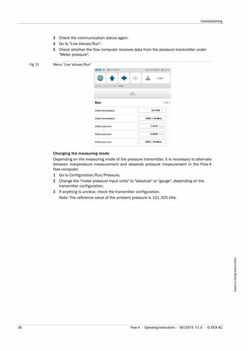
4 Go to "Live Values/Run".
5 Check whether the flow computer receives data from the pressure transmitter under "Meter pressure".
Fig. 31 Menu "Live Values/Run"
Changing the measuring mode
Depending on the measuring mode of the pressure transmitter, it is necessary to alternatebetween overpressure measurement and absolute pressure measurement in the Flow-Xflow computer.
1 Go to Configuration/Run/Pressure.
2 Change the "meter pressure input units" to "absolute" or "gauge", depending on the transmitter configuration.
3 If anything is unclear, check the transmitter configuration.
Note: The reference value of the ambient pressure is 101.325 kPa.
38 Flow-X · Operating Instructions · 8015675 V 1.0 · © SICK AG

Commissioning
Subj
ect t
o ch
ange
with
out n
otic
e
Fig. 32 Configuration/Run/Pressure
4.4.4 Temperature transmitter
Checking the communication status
1 Go to Communication/Temperature Transmitter/Temperature Communication.
2 Check the "Communication Status“:
When the "Communication Status" is set to "OK", the correct device ID has already been set on the flow computer.
Changing the device ID
1 Go to Communication/Temperature Transmitter/Temperature Communication.
2 Change the "HART slave ID" to the device ID set in the device.
3 Check the communication status again.
4 Go to "Live Values/Run".
5 Check whether the flow computer receives data from the temperature transmitter under "Meter temperature".
Flow-X · Operating Instructions · 8015675 V 1.0 · © SICK AG 39

Commissioning
Subj
ect t
o ch
ange
with
out n
otic
e
4.4.5 Clearing log files and reportsAfter the start-up of all devices, it is recommended to clear the event logs and reports cre-ated during the commissioning in the Flow-X flow computer.
Select and confirm "Reset totals", "Clear reports", "Clear archives" and "Clear print-queue".
Fig. 33 System/Reset
40 Flow-X · Operating Instructions · 8015675 V 1.0 · © SICK AG

Commissioning
Subj
ect t
o ch
ange
with
out n
otic
e
4 . 5 Metrological Settings
The following settings are required by MID (Measuring Instrument Directive).
▸ Select: Display > Metrological, Accountable alarm
This display is only visible if “MID compliance” (Configuration, Overall setup, Overall setup) is enabled.
Table 6 Metrological settings
Setting Security level DescriptionQmin 1000 Low range value (minimum allowable flow rate) of the flow
meter. If the flow rate is below this value then the accountable alarm is raised
Qmax 1000 High range value (maximum allowable flow rate) of the flow meter. If the flow rate is above this value then the accountable alarm is raised
Flow-X · Operating Instructions · 8015675 V 1.0 · © SICK AG 41

Commissioning
Subj
ect t
o ch
ange
with
out n
otic
e
42 Flow-X · Operating Instructions · 8015675 V 1.0 · © SICK AG

Troubleshooting
Subj
ect t
o ch
ange
with
out n
otic
e
Flow-X
5 Troubleshooting
Testing gas flow meter communication
Interface configurations of gas meter connection
Flow-X · Operating Instructions · 8015675 V 1.0 · © SICK AG 43

Troubleshooting
Subj
ect t
o ch
ange
with
out n
otic
e
5 . 1 Testing gas flow meter communication
MEPAFLOW CBM
Software MEPAFLOW600 CBM is mainly used in the following for configuring theFLOWSIC600 gas flow meter.
Fig. 34 MEPAFLOW600 CBM graphical user interface
For more details concerning the software and its use, see Section "MEPAFLOW600 CBM" of the Operating Instructions FLOWSIC600.
44 Flow-X · Operating Instructions · 8015675 V 1.0 · © SICK AG

Troubleshooting
Subj
ect t
o ch
ange
with
out n
otic
e
Connection check
If there is no flow on the gas flow meter itself, it is still possible to check the connection ofthe device.
1 Go to Flow Meter/Smart Meter in the menu of the Flow-X flow computer.
"Flow meter input failure" reads O, since there is no error
As there is no gas flow, "Meter active" is set to "No".
Fig. 35 Flow Meter/Smart Meter
2 Open the MEPAFLOW600 CBM software on the computer connected to the gas flow meter.
3 Change from File/Operation Mode to File/Configuration Mode.
4 Confirm the message with "Yes".
Fig. 36 Change to configuration mode
5 Select the "Parameters" option under "Meter" in the menu bar.
6 Select "Meter setup" in the menu.
7 Select register #7166 "TestFlowRate".
8 Change the register value to any optional value.
9 Confirm the input with "Write register".
For more details concerning the installation and use of MEPAFLOW600 CBM, see Section "Connecting to the FLOWSIC600 with MEPAFLOW600 CBM" of Operating Instructions "FLOWSIC600".
The flow computer shows the error message "Flow meter measurement fail" which can be ignored until returning to Operation Mode. The error message then disappears automatically.
Flow-X · Operating Instructions · 8015675 V 1.0 · © SICK AG 45

Troubleshooting
Subj
ect t
o ch
ange
with
out n
otic
e
Fig. 37 Determining the flow rate
10 Go to "Flow rates" in the menu of the flow computer.
11 Check whether the value for "Gross volume flow rate" matches the set register value.
Fig. 38 Menu "Flow rates"
12 Then return to "Operation Mode" via MEPAFLOW600.
5 . 2 Interface configurations of gas meter connection
5.2.1 Configuration with MEPAFLOW600 CBM1 Open the MEPAFLOW600 CBM software on the computer which is connected to the gas
flow meter.
2 In the menu bar, change from "Operation Mode" to "Configuration Mode"under "File".
46 Flow-X · Operating Instructions · 8015675 V 1.0 · © SICK AG

Troubleshooting
Subj
ect t
o ch
ange
with
out n
otic
e
3 Confirm the message with "Yes".
4 Select the "Parameters" option under "Meter" in the menu bar.
5 Select "Meter setup" in the menu and then menu item "Serial interface".
6 Select register 5023 "RS485-1(33/34)ControlReg:".
Fig. 39 Change the interface
Flow-X · Operating Instructions · 8015675 V 1.0 · © SICK AG 47

Troubleshooting
Subj
ect t
o ch
ange
with
out n
otic
e
7 On the right side of the screen, under "Protocol", change the communication type, baud rate, data bits, parity and stop bits.
Fig. 40 Interface
8 Confirm the input with "Write register".
Please note: Settings on the interface only become effective when returning to "Opera-tion Mode".
5.2.2 Configuration with the Flow-X flow computer, webserver or module screenLogin is required to change settings. Proceed as explained in chapter "Connection ofDevices".
1 Go to System/Modules/Module 1/COM Ports/COM1.
2 Change baud rate, data bits, parity and stop bits to the values set in MEPAFLOW600 CBM.
Fig. 41 System/COM Ports/COM1 > Change screen RS485
The values specified here are the standard values defined in the Flow-X flow computer.
Deviating configurations must be set in the Flow-X flow computer and in FLOWSIC600
48 Flow-X · Operating Instructions · 8015675 V 1.0 · © SICK AG

Troubleshooting
Subj
ect t
o ch
ange
with
out n
otic
e
5 . 3 Checking the measuring mode setting of the pressure transmitter▸ Go to "Live Values".
The pressure transmitter does not yet measure the pressure
● The value of "Meter Pressure" for absolute pressure is "1".
● The value of "Meter Pressure" for overpressure is "0".
The set measuring mode of the transmitter has to be changed if this is not the case.
Pressure transmitter already measuring
The set measuring mode of the transmitter has to be changed if both the values of "Meterpressure" for absolute pressure and for overpressure are negative and the error message"Compressibility calculation error" is shown.
Changing the transmitter measuring mode
1 Go to Configuration/Run/Pressure.
2 Change the "meter pressure input units" to "absolute" or "gauge", depending on trans-mitter configuration.
If anything is unclear, check the transmitter configuration.
Note: The reference value of the ambient pressure is 101.325 kPa.
5 . 4 Checking analog temperature transmittersIf incorrect temperature values or error messages are indicated by an analog temperaturetransmitter, check the scaling set for the transmitter.
Adapting the scale in the flow computer to the working range of the transmitter
1 Go to IO/Configuration/Analog inputs.
2 Set "Analog input 2 full scale" to the maximum value of the indicator value of the tem-perature transmitter.
3 Set "Analog input 2 zero scale" to the minimum value of the indicator value of the tem-perature transmitter.
Please note: Minor deviations are possible.
Flow-X · Operating Instructions · 8015675 V 1.0 · © SICK AG 49

Troubleshooting
Subj
ect t
o ch
ange
with
out n
otic
e
50 Flow-X · Operating Instructions · 8015675 V 1.0 · © SICK AG
Appendix
Subj
ect t
o ch
ange
with
out n
otic
e
Flow-X
6 Appendix
Conformities
General specifications
I/O specifications
Dimensions
Wiring examples
Flow-X · Operating Instructions · 8015675 V 1.0 · © SICK AG 51

Appendix
Subj
ect t
o ch
ange
with
out n
otic
e
6 . 1 Conformities
6.1.1 CE certificateThe Flow-X flow computer has been developed, manufactured and tested in accordancewith the following EC directives:
● EMC Directive 2004/108/EC
● MID Directive 2004/22/EC
Conformity with above directives has been verified. The equipment has been designatedthe CE label.
6.1.2 Standard compatibility and type approvalThe Flow-X flow computer conforms to the following norms, standards or recommenda-tions:
● EN 61000-6-4
● EN12405-1, A2
● AGA 10
● AGA 8
Type approval for commercial or custody transfer has been granted by the relevant authori-ties, e.g.:
● MID Approval, NMI (Nederlands Meetinstituut): T10548
6 . 2 General specifications
Other specifications
Item Type Description QuantityTemperature Operating Operating range temperature +5 … +55 °CTemperature Storage Storage range temperature –20 … +70 °CProcessor Freescale i.MX processor with math coprocessor, and FPGA 400 MHzMemory RAM Program Memory 50 MBFlash FRAM Permanent storage / data logging storage 32 MBData Storage Memory
MMC Storage memory for data logging 1024 MB
Clock RTC Real time clock with internal lithium cell, Accuracy better than 1 s/day
Item SpecificationMTBF 5 years minimumEMC EN 61326-1997 industrial locations
EN 55011Casing EN 60950
52 Flow-X · Operating Instructions · 8015675 V 1.0 · © SICK AG

Appendix
Subj
ect t
o ch
ange
with
out n
otic
e
6 . 3 Flow-X/M I/O specifications
6.3.1 I/O signal specifications Table 7 Analog signals specifications
Signal Nr Type DescriptionAnalog input 6[1]
[1] Total number of analog inputs + HART inputs = 6.
4 … 20 mA,0 … 20 mA,0 … 5 V, or 1 … 5 V
Analog transmitter inputHigh accuracy (error <0.008 % FS, resolution 24 bits)For (for example) 3xdP, P, T. Inputs are fully floating (optically isolated).
Temperature input 2 PRT Analog Pt100 input. –220 … +220 °C for 100 Ω input. Resolution 0.02 °C Max. error:● 0 … +50 °C: 0.05 °C● –220 … +220 °C: 0.5 °C
Hart modems 4[1] HART Loop inputs for HART transmitters, on top of the first 4 analog input signals.
Analog output 4 4 … 20 mA,0 … 20 mA, or 1 … 5 V.
Analog output for PID, pressure control valve. 12 bits A DC, 0.075 % fs. Update rate 0.1 s.
Table 8 Digital signals specifications
Signal Nr Type DescriptionDual pulse input 1[1]
[1] Total number of digital inputs + digital outputs + pulse outputs + density inputs + sphere detector inputs = 16.
High impedance High speed USM meter input, pulse count. Trigger level 0.5 V. Max. level 30 V. Frequency range 0 … 5 kHz (dual pulse), or 0 … 10 kHz (single pulse). Compliant with ISO6551, IP252, and API 5.5. True Level A implementation.
Digital input 16[1] High impedance Digital status input, or prover inputs. 0.5 ms detect update rate for 2 inputs, others 250 ms max.
Digital output 16[1] Open collector Digital output for relays etc. (0.5 A DC). Rating 100 mA @24 V. Update rate at cycle time.
Prover output 1[1] Open collector Two related pulse outputs, for proving applications. One output is the highest value of the dual pulse inputs, and the other output the difference between the dual input pulses. The outputs are On-Off-HighZ.
Pulse output 4[1] Open collector Max. 100 Hz
Table 9 Communication specifications
Signal Nr Type DescriptionSerial 2 RS485/422/232 Multi-purpose serial communication interface
Minimum 110 baud, maximum 256000 baudEthernet 2 RJ45
100 Mbit/sEthernet interface - TCP/IP
Flow-X · Operating Instructions · 8015675 V 1.0 · © SICK AG 53

Appendix
Subj
ect t
o ch
ange
with
out n
otic
e
6.3.2 Flow calculation specifications
6.3.3 Supported devices
Table 10 Certified flow calculations
Library of certified flow calculationsSupports AGA9API chapter 21.1ISO 6976 (all editions)NX19SGERGPTZGPA 2172ASME 1967 (IFC-1967) steam tables,IAPWS-IF97 steam density
Table 11 Standard flow calculations
Standard flow calculationsBatch and period recalculation (meter factor, BS&W, density, etc.)Unlimited number of period and batch totals and flow and time weighted averages. Periods can be of any type. Maintenance totalizers are supportedCalibration curve up to unlimited number of points (linear and polynomial).Prover support: uni-directional, bi-directional (2 / 4 detector inputs), compact prover, master meter, dual chronometry, pulse interpolation.Control:– PID control– valve control – prove control – batch controlAll common spreadsheet functions to obtain maximum flexibility.
Table 12 Standard supported devices
Standard supported devicesUltrasonic Flow Meters– SICK FLOWSIC product familyAll major gas chromatographs– All major gas chromatographs– ABB– Daniel– Instromet– Siemens– Any Modbus-supporting Gas chromatograph
54 Flow-X · Operating Instructions · 8015675 V 1.0 · © SICK AG

Appendix
Subj
ect t
o ch
ange
with
out n
otic
e
6 . 4 Power consumption
The power supply input circuits of the Flow-X/P0 and the Flow-X/M flow modules areequipped with an auto-fuse, rated at 30 V DC and 1.1 A each.
E.g. a Flow-X/P4, which is a Flow-X/P with 4 Flow-X/M flow modules has a nominal powerconsumption of 1.5 A (0.3 A of Flow-X/P0 + 4 × 0.3 A for each flow module) and a peakconsumption of 4.0 A at startup.
6 . 5 Weight
Table 13 Power consumption at 24 V DC [1]
[1] Excluding supply of external transmitter loops.
Device Nominal value Peak value at startupFlow X/P0 0.3 A 0.8 AFlow X/M (flow module) 0.3 A 0.8 A
Table 14 Weight of single components
Component WeightFlow-X/M (single flow module) 0.8 kg (1.8 lbs)Flow-X/P0 (without flow modules) 3.6 kg (8.0 lbs)
Table 15 Weight of combined products
Product WeightFlow X/P1 4.4 kg (9.8 lbs)Flow X/P2 5.2 kg (11.6 lbs)Flow X/P3 6.0 kg (13.4 lbs)Flow X/P4 6.8 kg (15.2 lbs )
Flow-X · Operating Instructions · 8015675 V 1.0 · © SICK AG 55

Appendix
Subj
ect t
o ch
ange
with
out n
otic
e
6 . 6 DimensionsFigure 42 Flow-X/P dimensions
front view side view
[inch] mm rear view [inch] mm
56 Flow-X · Operating Instructions · 8015675 V 1.0 · © SICK AG

Appendix
Subj
ect t
o ch
ange
with
out n
otic
e
Figure 43 Flow-X/P bracket dimensions
Figure 44 Flow-X/ST dimensions
side view
[inch] mm
Flow-X · Operating Instructions · 8015675 V 1.0 · © SICK AG 57

Appendix
Subj
ect t
o ch
ange
with
out n
otic
e
Figure 45 Flow-X/S horizontal dimensions
Figure 46 Flow-X/S vertical dimensions
58 Flow-X · Operating Instructions · 8015675 V 1.0 · © SICK AG

Appendix
Subj
ect t
o ch
ange
with
out n
otic
e
Figure 47 Flow-X/S wall mount dimensions
Figure 48 Flow-X/S wall mount side view dimensions
Flow-X · Operating Instructions · 8015675 V 1.0 · © SICK AG 59

Appendix
Subj
ect t
o ch
ange
with
out n
otic
e
6 . 7 Wiring examples
Figure 49 Non-intrinsically safe installation
= +
12
34
56
78
910
11
12
13
Non Hazard Area
EN
60
07
9-1
4
24V DC +
24V Gnd
ExplosionHazard Location
F.
Rif
fer
SICK Engineering GmbH
Bergenerring 27
01458 Ottendorf-Okrilla
Tel.: +(49) 35205 524 10
13.03.2013
Date
created
released
Standard
Date Name
Rev. ECN
Configuration: Flow-X/P1
Sheet 1
FLOWSIC 600
RS 485
Modbus
31+
32-
33+
34-
51+
52-
41+
42-
81+
82-
1 (+)
2 (-)
.
For further details see
!
WARNING!
Incorrect cabling may cause
operation manual of the
individual device.
RS485 Modbus - approx. impedance 120 Ohm
maximum length: 500 m
EC-Typ-Examination Certificate
For Safety/Entity - Parameters see
Compliance CSA 1298901
Certificate of Conformity
TÜV 01 ATEX 1766 X resp. Certificate of
Flowsic 600 Certificates
Network
SCADA
2x2x0,5 mm²
Li2YCYv(TP)
2x2x0,5 mm²
Li2YCYv(TP)
2x2x0,5 mm²
Li2YCYv(TP)
2x1,5 mm²
NYY-O
the devices to fail!
Flow computer Flow-X
2x1,5 mm²
NYY-O
Flow-X/P1
X1A
ETH 1
ETH 2
24 VDC
Power supply
0V
0V
+24V
TRx-
TRx+
+AI1
-AI1
+AI2
-AI2
Pressure
Temperature
(internally linked)
5-6-
1
2
5
9
11
32
33
34
35
2+1+
ProcessTransmitter
p
Pressure
PE
4...20 mA or HART
loop powered
T
ProcessTransmitter
TemperaturePE
4...20 mA or HART
loop powered
Non-intrinsically-safe installation / Ex e
Fuses for field terminals:
Very fast acting type (FF-Type)
before change.
Additional surge protection is
recommended in case of powerful or
recurrent strokes of lightning.
In case of blow out look for reason
Screen
Screen
Screen
Fuse 100mAsuper fast
Fuse 100mAsuper fast
Fuse 100mAsuper fast
Fuse 1Afast
-X
Drawing: E_94816
60 Flow-X · Operating Instructions · 8015675 V 1.0 · © SICK AG

Appendix
Subj
ect t
o ch
ange
with
out n
otic
e
Figure 50 Intrinsically safe installation
= +
12
34
56
78
910
11
12
13
Non Hazard Area
EN
60
07
9-1
4
24V DC +
24V Gnd
ExplosionHazard Location
Intrinsically-safe installation / Ex i
F.
Rif
fer
SICK Engineering GmbH
Bergenerring 27
01458 Ottendorf-Okrilla
Tel.: +(49) 35205 524 10
13.03.2013
Date
created
released
Standard
Date Name
Rev. ECN
Configuration: Flow-X/P1
Sheet 1
FLOWSIC 600
RS 485
Modbus
31+
32-
33+
34-
51+
52-
41+
42-
81+
82-
1 (+)
2 (-)
.
For further details see
!
WARNING!
Incorrect cabling may cause
operation manual of the
individual device.
RS485 Modbus - approx. impedance 120 Ohm
maximum length: 500 m
EC-Typ-Examination Certificate
For Safety/Entity - Parameters see
Compliance CSA 1298901
Certificate of Conformity
TÜV 01 ATEX 1766 X resp. Certificate of
Flowsic 600 Certificates
National regulation must be observed.
in EU in accordance with EN 60079-14
in North America
in accordance with
NEC and CEC, see
Intrinsic safety installation:
Network
SCADA
Ex
safety barrier
Power Supply
24 VDC +
-
+
-
Intrinsic safety circuits
Non Intrinsic safety circuits
Screen
Screen
Screen
Screen
Screen
Screen
2x2x0,5 mm²
Li2YCYv(TP)
2x2x0,5 mm²
Li2YCYv(TP)
2x2x0,5 mm²
Li2YCYv(TP)
2x2x0,5 mm²
Li2YCYv(TP)
2x2x0,5 mm²
Li2YCYv(TP)
2x2x0,5 mm²
Li2YCYv(TP)
2x1,5 mm²
NYY-O
2x1,5 mm²
NYY-O
2x1,5 mm²
NYY-O
2x1,5 mm²
NYY-O
2x1,5 mm²
NYY-O
Control Drawing 781.00.02 (for FL600)
the devices to fail!
Flow computer Flow-X
2x1,5 mm²
NYY-O
Flow-X/P1
X1A
ETH 1
ETH 2
24 VDC
Power supply
0V
0V
+24V
TRx-
TRx+
+AI1
-AI1
+AI2
-AI2
Pressure
Temperature
(internally linked)
5-6-
1
2
5
9
11
32
33
34
35
2+1+
ProcessTransmitter
p
Pressure
PE
4...20 mA or HART
loop powered
T
ProcessTransmitter
TemperaturePE
4...20 mA or HART
loop powered
Ex
safety barrier
4...20mA or HART
24VDC
+
-
+
-
+
-
Ex
safety barrier
4...20mA or HART
24VDC
+
-
+
-
+
-
Ex
safety barrier
24VDC
RS485 / 2 wire
TRx+
TRx-
+
-
TRx+
TRx-
Drawing: E_94817
Flow-X · Operating Instructions · 8015675 V 1.0 · © SICK AG 61

8015
675/
2013
-03
(V1.
0) |
Sub
ject
to c
hang
e w
ithou
t not
ice
SICK AG | Waldkirch | Germany | www.sick.com
SICK worldwide
You will find our local subsidiary
or agency at:
www.sick.com
Your local sales and service partner
Flow-X