Embed Size (px)
Citation preview
INSTALLATION & USER GUIDE
OCTAVE® ULTRASONIC FLOW METER
FLOW METERS

2 • OCTAVE ULTRASONIC FLOW METER INSTALLATION & USER GUIDE

OCTAVE ULTRASONIC FLOW METER INSTALLATION & USER GUIDE • 3
General Safety and Information ........................................................................................4
Warranty ................................................................................................................................4
Included Items ......................................................................................................................4
Operation ...............................................................................................................................4
Specifications .......................................................................................................................5
Dimensions & Weights .......................................................................................................5
Installation
Handling the Meter .............................................................................................6
Installation Position & Location .......................................................................6
Installation Notes ................................................................................................7
Installation Examples .........................................................................................8
Pipe Flanges .........................................................................................................8
Start-Up ................................................................................................................8
Display ... ................................................................................................................................9
Outputs
Electrical Outputs ................................................................................................9
Pulse Output Module .........................................................................................9
Analog Output Module ....................................................................................10
Output Module Installation ...............................................................................................11
Module Wire Connectivity ................................................................................................12
Grounding Instructions .....................................................................................................13
Grounding Parts .................................................................................................................14
TABLE OF CONTENTS

4 • OCTAVE ULTRASONIC FLOW METER INSTALLATION & USER GUIDE
• Do not install, operate or maintain this flow meter without reading, understanding and following the factory-supplied instructions. Otherwise, injury or damage may result.• Read these instructions carefully before beginning installation and save them for future reference.• Observe all warnings and instructions marked on the product and in this guide.• Consider special handling and lifting instructions to avoid damage or personal injury.• If the product does not operate normally, refer to the service instructions or call your Netafim Representative. • There are no operator-serviceable parts inside this product.• NOTE: The Octave sensors are very sensitive and are not designed to be modified by the end user. Any modifications void the warranty.
GENERAL SAFETY & INFORMATION
WARRANTYOctave ultrasonic meters are warranted to be free from original defects in materials and workmanship for a period up to five (5) years. If the meter encounters a problem, Netafim USA will choose either to cover the cost of repair or replacement based on a five (5) year pro-rated schedule as follows: • Year 0 through Year 2: 100%• Year 2 through Year 3: 75%• Year 3 through Year 4: 50%• Year 4 through Year 5: 25%All Octave meters must be installed with a Netafim branded Combination Air/Vacuum or Continuous Acting Air Vents to qualify for the five (5) year pro-rated product warranty. Consult Netafim for recommendations.
INCLUDED ITEMS• One Octave ultrasonic meter, size as indicated on the packaging box, pieced together into a complete compact system (flow tube plus electronics).• One pre-installed Output Module, either Digital or Analog (if ordered).• Documentation includes: Installation/User Manual, Report of Factory Meter Settings and Certificate of Calibration Data.• This product has been thoroughly inspected, tested and calibrated before shipment and is ready for operation. • After carefully unpacking the meter, inspect for shipping damage before attempting to install. If any damage is found, immediately contact the responsible transportation company and Netafim USA.
• The Octave's measurement method is based on an ultrasonic, transit-time, dual-beam sensors that determines the length of time it takes an ultrasonic wave to travel the distance between the two sensors located in the meter's body. The sensors function as both sender and receiver, each one alternating these functions so that the ultrasonic wave travels both with and against the direction of the flow. Because the ultrasonic wave travels slower against the flow than with the flow, the time difference of the two waves allows the meter to determine the flow rate. • The Octave is a battery-powered precision flow meter designed for linear, bidirectional flow measurement of water. • Flow measurement values can be transferred through the standard digital or analog output. • The Octave display can be set up for a wide range of outputs.
OPERATION

OCTAVE ULTRASONIC FLOW METER INSTALLATION & USER GUIDE • 5
• Cast Iron Available in: 2”, 3”, 4”, 6”, 8”, 10” and 12” (Flow Range of <1 - 5,500 GPM)• SST 316 Available in: 2”, 3”, 4”, 6” and 8” (Flow range of <1 - 2,800 GPM)• Meter Body Configuration: Epoxy-coated Ductile Iron or Grade 316 Stainless Steel• Inlet/Outlet: Flange• Maximum Working Pressure: 230 psi • Liquid Temperature: 32° to 122° F (0.1º to 50ºC)• Precision Class: ISO 4064 rev.2005, Accuracy Class 2• Configuration: Compact - display is built into the unit• Power Source: 2 ‘D’ size non-replaceable Lithium Batteries - 10 year warranted lifetime• Environmental Protection: NEMA 6P + (IP68+), Ambient operation temperature for display: -13° to 131° F (-25° to 55° C)• Display Units: Multi-line, programmable 9 digit LCD display• Volume Display Options: 1. Net (Forward less Reverse), 2. Forward Only, 3. Forward and Reverse Alternating• Outputs (optional): 1. Dual Digital Pulses (open collector or dry contact), 2. 4-20 mA (powered loop), 3. Encoder output• Connections: Flanges ANSI ISO • Severity Levels: Environmental class C, mechanical class M1, Electromagnetic environment class E1• Pressure Loss: ∆P 16
SPECIFICATIONS
DIMENSIONS & WEIGHTS
B
L
H
h
CAST IRON DIMENSIONS & WEIGHTS
2”3”4”6”8”10”12”
SIZE LENGTH (L) WIDTH (B)7.9”8.9”9.8”11.8”13.8”17.7”19.7”
6.5”7.9“8.7”11.2“13.4”15.9”19.2”
HEIGHT (H)7.5”8.3“8.8”11.1“13.1”15.9”19.3”
HEIGHT (h)1.6”3.5“4.1”5.5“6.5”8.0”9.6”
WEIGHT19.8 LBS.28.7 LBS.33.1 LBS.70.5 LBS.99 LBS.150 LBS.216 LBS.
STAINLESS STEEL DIMENSIONS & WEIGHTS
2”3”4”6”8”
SIZE LENGTH (L) WIDTH (B)10”12”14”18”20”
5.75”7.5“9”11“
13.5”
HEIGHT (H)6.75”8.5“9.9”10.9“12.9”
HEIGHT (h)2.1”3.5“4.5”5.1“6.4”
WEIGHT15 LBS.28 LBS.40 LBS.62 LBS.88 LBS.

6 • OCTAVE ULTRASONIC FLOW METER INSTALLATION & USER GUIDE
INSTALLATIONHANDLING THE METERIMPORTANT:
�
FLOW DIRECTION
�
FLOW
DIR
ECTI
ON
�
FLOW DIRECTION
�
FLOW DIRECTION
�FLO
W D
IREC
TIO
N
PROPER INSTALLATIONEXAMPLES
WRONG INSTALLATIONEXAMPLES
• DO NOT use chains or wire cable to lift the Octave. To protect the epoxy coating, only use a nylon lifting strap with appropriate weight capacity.• DO NOT lift the Octave by the electronic housing unit.• DO NOT carry the Octave by its lid.• DO NOT use bolt holes for grip when carrying the Octave.• DO NOT position the meter on its electronic housing unit.• When bolting the meter to pipe flanges, use washers on both nuts and bolts to protect the epoxy coating of the Octave. • When handling the meter avoid hard blows, jolts or impacts.
INSTALLATION POSITION & LOCATIONInstallation requirements for position and location are illustrated below.

OCTAVE ULTRASONIC FLOW METER INSTALLATION & USER GUIDE • 7
INSTALLATIONINSTALLATION NOTES• For proper flow measurements, the Octave’s measuring chamber should be completely full at all times. Non-wetted
sensors show loss of signal. Though this will not cause damage to the meter, it will however, not measure flow and display zero.
• Flow direction: the Octave is a bidirectional flow meter. Note the indicating arrow on the Octave display for forward and backward flow.
• Leave the lid closed except when reading the meter. • Do not expose the Octave to excessive vibration. To avoid vibration, support the pipeline on both sides of the meter.• Ambient working temperature: -13° to 131° F• Water working temperature: 32° to 122° F• To avoid measuring errors due to air in the flow tube, observe the following precautions: - Since air collects at the highest point in the system, installation of the flow meter should be at the lowest point - Always install control valves downstream of the meter in order to avoid cavitation - Never install the meter on a pump suction side in order to avoid cavitation• It is required to install Netafim branded Combination Air/Vacuum or Continuous Acting Air Vents right before the Octave
meter. Consult Netafim for recommendations.
PIPE FLANGES• Refer to the standard dimensional drawings for flange spacing, accommodating for the thickness of gaskets. • Install meter inline with the pipe axis. The pipe flange faces must be parallel to each other.
• Permissible length deviation: Lmax - Lmin 0.5mm (0.02”).
START-UP• Check that the meter has been installed correctly.• Check that the flow rate and volume units are correctly pre-programmed on the display.• Check that the output module is correctly attached.

8 • OCTAVE ULTRASONIC FLOW METER INSTALLATION & USER GUIDE
INSTALLATIONINSTALLATION EXAMPLES FOR ACHIEVING TOP PERFORMANCEThe following examples are recommendations for achieving top performance. Two (2) diameters of straight pipe are required when installing a 90° elbow before or after the meter. (See Figure 1)
Two (2) diameters of straight pipe are required when installing the meter upstream or downstream of a valve, tee connection or other source of significant turbulence. (See Figures 2 and 3) NOTE: The installation of the meter upstream of a pump or large valve is not recommended due to potential cavitation issues.
Five (5) diameters of straight pipe downstream of a pump (before the meter) and Two (2) diameters of straight pipe downstream of the meter are required. (See Figure 4) NOTE: When the meter is downstream of the pump, Netafim recommends additional straight pipe to ensure accurate measurements.
Meter can be installed horizontally or vertically with the water flowing up. It is not recommended for installation where the direction of flow is below the horizontal plane. (See Figure 5)
To eliminate air in the pipeline and maintain accuracy, use of and proper placement of Air Vents is required. We recommend a Combination Air/Vacuum Release Air Vent or the Pro Air Vent.
Recommended Air Vent placement: 3” and 4” meters place air vent 12” to 18” before the meter; 6” and 8” meters place the air vent 18” to 24” before the meter; 10” and 12” meters place the air vent 30” to 36” before the meter.
Installing a Check Valve downstream of the meter creates back pressure to aid in the meter filling with water.
NOTE:Air Vents can be placed on a 6” to 12” riser for evacuation of a larger volume of air.
FLOW DIRECTION
2
2
FIGURE 1(2) PIPE DIAMETERS BEFORE & AFTER 90°ELBOWS
FLOW DIRECTION
2
2
FIGURE 2(2) PIPE DIAMETERS BEFORE & AFTER METER
FLOW DIRECTION
2
FIGURE 3(2) PIPE DIAMETERS BEFORE TEE CONNECTION
�
�
2
�
�
5
�
FLOW DIRECTION
FIGURE 4(5) PIPE DIAMETERS AFTER PUMP (BEFORE METER) & (2) PIPE DIAMETERS AFTER METER
FLO
W D
IREC
TIO
N
2
2
FIGURE 5(2) PIPE DIAMETERS BEFORE & AFTER 90° ELBOWS IN VERTICAL INSTALLATIONS
�
FLOW DIRECTION
�
�
2
�
�
2
FIGURE 6(2) PIPE DIAMETERS AFTER STRAINERS

OCTAVE ULTRASONIC FLOW METER INSTALLATION & USER GUIDE • 9
PULSE MODULE OUTPUT DIAGRAM
OUTPUTS
PULSE OUTPUT CHARACTERISTICSOUTPUTS TYPE
CABLE LENGTH - SUPPLIEDMAXIMUM CABLE LENGTH*MAXIMUM APPLIED VOLTAGE
DRAIN5 FEET
1,640 FEET30 VDC
* The Maximum cable length depends on the cable type, controller and electrical noise level
PULSE OUTPUT CABLESWIRERED
GREENBLACKOPEN
RING TERMINAL
FUNCTIONPULSE OUT #1PULSE OUT #2GROUNDGROUND / SHIELDGROUND
CABLE
LONGCABLE
SHORT CABLE
WARNING: Signal connection polarity is mandatory.
PULSE OUTPUT MODULE• Open collector that allows current
loading of 200mA and up to 50 VAC or 50VDC
1
100ohm
100ohm
1
1
1
1
ShortCable
LongCable
Octave Pulse v5.1
Read-outInstrument
EMI / RFI /Over VoltagePROTECTION
Ground Cable
RED
GREEN
BLACK
SHIELD
Pulse#1
Pulse#2
GND
GROUND
ELECTRICAL OUTPUTS• The Octave has several output options: - Dual pulse output for volumes - Analog output (4-20mA) for flow
VOLUME UNITS
FLOW RATE UNITS
LEAK DETECTOR
BATTERY LEVEL
ALARM/ERROR
OUTPUT MODE
FLOW DIRECTION
Each Octave is pre-programmed before shipment for an instantaneous flow rate in Gallons per Minute (GPM) and the specified user's requirements for:
• Output Resolution for Optional Pulsed Output
NOTE: Programming software is not available to the end user. Once the meter is programmed, it can only be reset by Netafim.
DISPLAY

10 • OCTAVE ULTRASONIC FLOW METER INSTALLATION & USER GUIDE
OUTPUTSANALOG OUTPUT MODULE (4-20mA)• The current output is a passive 4-20mA.• 4mA is always ‘0’ zero flow and the 20mA is factory programmable
according to customer requirements. If the customer does not specify, 20mA will be the maximum flow rate.
ShortCable
LongCable
GROUND
Octave4-20mAModule
Shield
GROUND
Read-out+ -
Instrument
(+)
(-)
ANALOG MODULE OUTPUT DIAGRAM
ANALOG MODULE OUTPUT CABLESWIRERED
BLACKOPEN
RING TERMINAL
FUNCTIONCURRENT LOOP +CURRENT LOOP -GROUND / SHIELDGROUND
CABLE
LONGCABLE
SHORT CABLE
WARNING: Signal connection polarity is mandatory.
ANALOG OUTPUT CHARACTERISTICSOUTPUTS TYPE
CABLE LENGTH - SUPPLIEDMAXIMUM CABLE LENGTH*LOOP SUPPLY VOLTAGEOUTPUT IMPEDANCE
4-20mA OUTPUT5 FEET
1,640 FEET12 - 24 VDC25 [M] TYP

OCTAVE ULTRASONIC FLOW METER INSTALLATION & USER GUIDE • 11
OUTPUT MODULE INSTALLATION
OUTPUT MODULE INSTALLATION KIT
All Octave meters are shipped with either a cover plate or communication module installed on the side of each meter. Even if the meter is not going to be read by radio or some other electronic unit, it is important to leave one of these devices installed on the Octave to prevent damage to the communication port. Installing an Octave without a cover plate or communication module would void any warranty.
If an output module was received separate from the Octave meter, please follow these steps to ensure proper installation of the module. Read through the instructions before attempting to remove the cover plate. The module came as a complete installation kit with the supplies shown in Picture 1.
PICTURE 1
O-Ring3mm Allen key
Octave module(2) Allen screws
3mm x 20 mm
STEP 1Remove the Sealing Cap from the Cover Plate (see Picture 2).
STEP 2Using the 3mm Allen Key provided, remove the Cover Plate (see Picture 3). Keep the Cover Plate and 3mm x 15mm screws for future use. The communication port is now exposed (see Picture 4).
STEP 3Place O-Ring around the 4-prong plug of the Output Module (see Pictures 5 and 6).
STEP 4Insert Output Module into the communication port (see Picture 7), with the cable pointing down. This will allow the slot inside the communication port to align with the groove on the module. Do not force the module into the communication port. This may cause damage to the pins. Secure into place using the 3mm x 20mm screws provided. Tighten until the screws stop (see Picture 8).
STEP 5Push the Sealing Cap into the lower screw hole (see Picture 9). Lock the Sealing Cap in place by firmly pushing it into place or gently tapping it in with a small hammer.
NOTE:If at any time the module needs to be removed, take caution not to allow dirt or water into the communication port. If the module is going to be removed for an extended period of time, reinstall the cover plate and the 3mm x 15mm screws.
PICTURE 2 PICTURE 3
PICTURE 4 PICTURE 5
PICTURE 6 PICTURE 7
PICTURE 8 PICTURE 9
12 • OCTAVE ULTRASONIC FLOW METER INSTALLATION & USER GUIDE
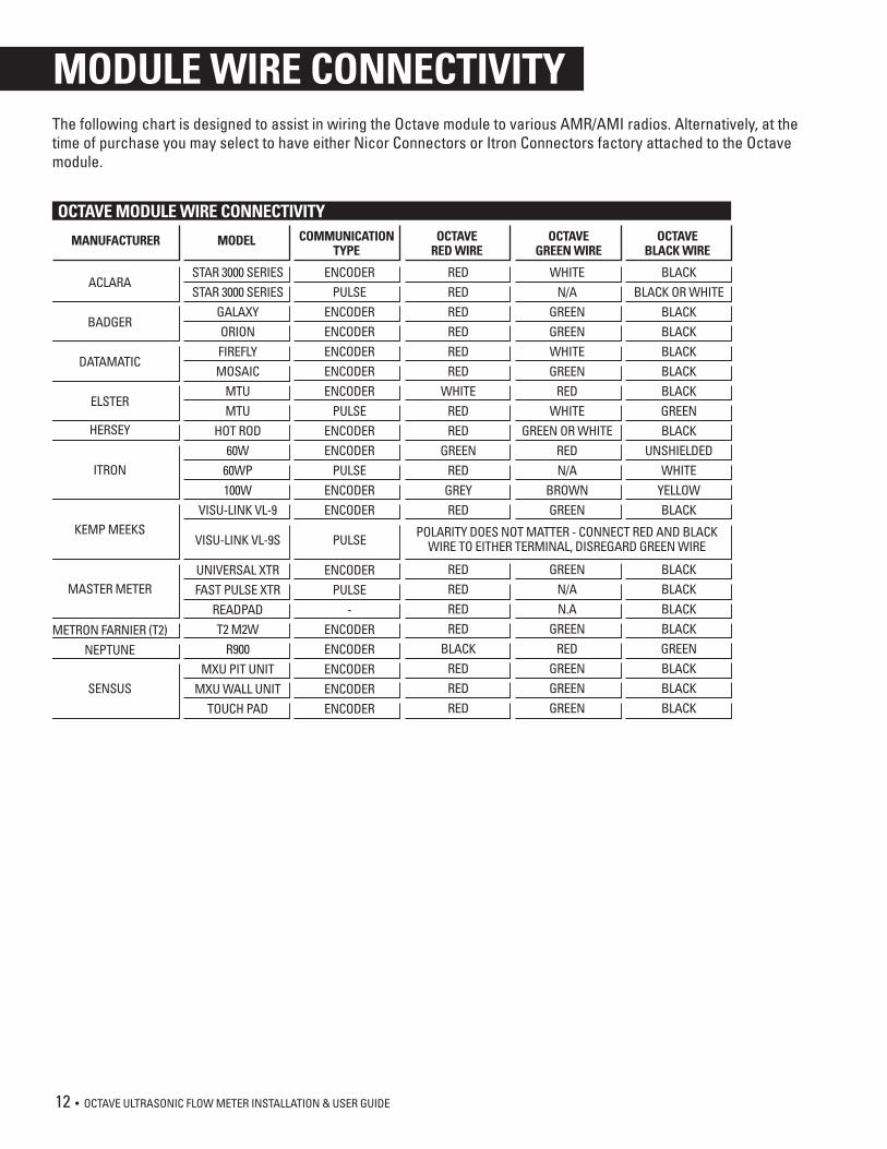
MODULE WIRE CONNECTIVITYThe following chart is designed to assist in wiring the Octave module to various AMR/AMI radios. Alternatively, at the time of purchase you may select to have either Nicor Connectors or Itron Connectors factory attached to the Octave module.
OCTAVE MODULE WIRE CONNECTIVITY
MANUFACTURER
ACLARA
BADGER
DATAMATIC
ELSTER
HERSEY
ITRON
KEMP MEEKS
MASTER METER
METRON FARNIER (T2)NEPTUNE
SENSUS
MODEL
STAR 3000 SERIESSTAR 3000 SERIES
GALAXYORIONFIREFLYMOSAIC
MTUMTU
HOT ROD60W
60WP100W
VISU-LINK VL-9
VISU-LINK VL-9S
UNIVERSAL XTRFAST PULSE XTR
READPADT2 M2W
R900MXU PIT UNIT
MXU WALL UNITTOUCH PAD
COMMUNICATIONTYPE
OCTAVERED WIRE
OCTAVEGREEN WIRE
OCTAVEBLACK WIRE
ENCODERPULSE
ENCODERENCODERENCODERENCODERENCODER
PULSEENCODERENCODER
PULSEENCODERENCODER
PULSE
ENCODERPULSE
-ENCODERENCODERENCODERENCODERENCODER
REDREDREDREDREDRED
WHITEREDRED
GREENRED
GREYRED
REDREDREDRED
BLACKREDREDRED
WHITEN/A
GREENGREENWHITEGREEN
REDWHITE
GREEN OR WHITEREDN/A
BROWNGREEN
GREENN/AN.A
GREENRED
GREENGREENGREEN
BLACKBLACK OR WHITE
BLACKBLACKBLACKBLACKBLACKGREENBLACK
UNSHIELDEDWHITE
YELLOWBLACK
BLACKBLACKBLACKBLACKGREENBLACKBLACKBLACK
POLARITY DOES NOT MATTER - CONNECT RED AND BLACKWIRE TO EITHER TERMINAL, DISREGARD GREEN WIRE

OCTAVE ULTRASONIC FLOW METER INSTALLATION & USER GUIDE • 13
GROUNDING INSTRUCTIONS
STEP 1Insert the M5 screw through the pre-assembled Ring Terminal Lug.
STEP 2Insert the flat washer on top of the Ring Terminal Lug.
STEP 3Insert the serrated washer on the flat washer.
STEP 4Attach to the Fork Terminal Lug and tighten (as shown in all three pictures).
STEP 5Insert flat washer and serrated washer on bolt - use the correct washers per bolt size (M16 or M20 respectively). Insert the bolt in the hole of the pipe’s flange - do not insert on meter’s flange.
STEP 6Slide the Fork Terminal Lug between the flat washer and serrated washer.
STEP 7Add serrated washer to the other side of the bolt (on meter’s flange side).
STEP 8Add the flat washer on top of the serrated washer.
STEP 9Add nut and tighten. Make sure the Fork Terminal Lug is in position.
14 • OCTAVE ULTRASONIC FLOW METER INSTALLATION & USER GUIDE
GROUNDING PARTS
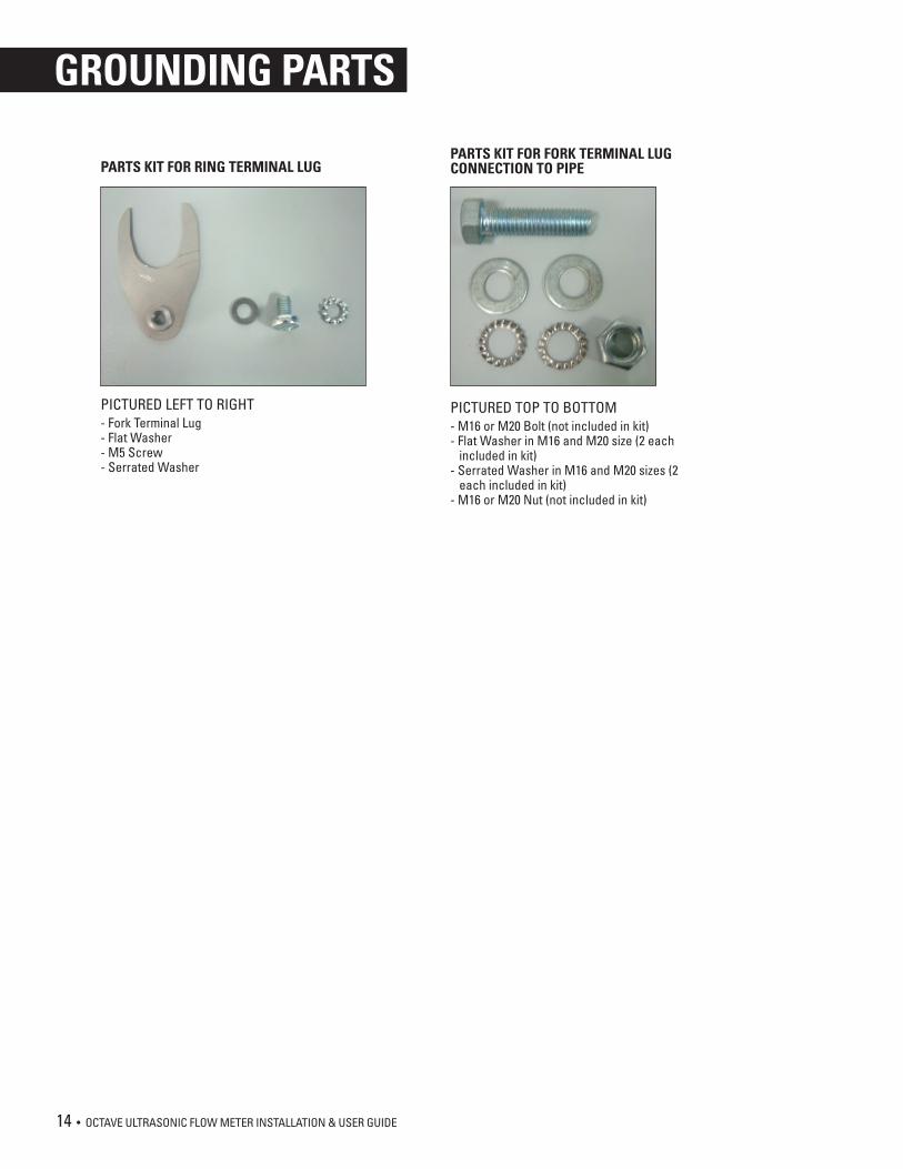
PICTURED LEFT TO RIGHT- Fork Terminal Lug- Flat Washer- M5 Screw- Serrated Washer
PARTS KIT FOR RING TERMINAL LUG
PICTURED TOP TO BOTTOM- M16 or M20 Bolt (not included in kit)- Flat Washer in M16 and M20 size (2 each included in kit)- Serrated Washer in M16 and M20 sizes (2 each included in kit)- M16 or M20 Nut (not included in kit)
PARTS KIT FOR FORK TERMINAL LUG CONNECTION TO PIPE

OCTAVE ULTRASONIC FLOW METER INSTALLATION & USER GUIDE • 15

NETAFIM USA5470 E. Home Ave.Fresno, CA 93727CS 888 638 2346www.netafimusa.com
MN-OCT-MAN 12/16