Embed Size (px)
Citation preview

Flow rates : Known
Obtain : heat capacities (Cp) heat of vaporization/condensation
Estimate : vapor loads in the column(design)
Obtain heat loads of all streams which change temperature/phase
Q. Is it possible to combine/integrate/match them?
Energy integration
Heat Exchanger Network(HEN)
Energy BalanceLevel 5

Synthesis of Heat Exchanger Networks
Questions
1. Why is it important to make a particular study of HENs ?• Considerable reductions can be made in the energy requirements of chemical process plants by the application of recently developed techniques ( often of the order of 20 ~ 302 )• The reductions in energy requirements can be achieved with reduced capital costs
2. Is it possible to predict the minimum utility requirements ( e.g. cooling water, steam, fuel, etc. ) in a HEN 3. Is it possible to predict the minimum number of HENs ? ( Heat exchange matches required are a network if the maximum amount of energy is to be required )4. Given affirmative answers to questions 2 and 3, can optimal networks be designed ?5. How can the design procedures be extended to incorporate other terms of equipment such as gas turbines, distillation columns
minT : HRAT (Heat Recovery Approach Temperature
냉각장치 : = 1~ 2℃
싼 utility 필요시 : = 30 ℃
minT
minT
Pinch - sequentialMIP - concurrent

Minimum utility requirements
Simple example – one hot and one cold stream
FCp Tsupply Ttarget
Stream (kw/ ) ( ) ( )℃ ℃ ℃(1) Hot 1 300 90(2) Cold 3 100 180
F : mass flow rate of stream ( kg / s )Cp ; heat capacity of stream ( kJ / kg )℃FCp [ kw / ] ℃
℃10min T
300℃
QH steam
180℃100℃
90℃
Qc Cooling water

Temperature – Enthalpy Plot
T℃
)(kwH
180℃
300
200
10090
100 200210
300260
Hotstream
10 ℃
Coldstream
0
T℃
)(kwH
300
200
10090
20 210 2600
Qc
QEX
PINCH
QH
“ PINCH “THOT – TCOLD=
minT

For
kwQkwQT
kwQkwQT
cH
cH
30;60;20
20;50;10
min
min
℃
℃
For
minTIncreasing cold stream curve moving to the right
Q vs Plot minT
10 20 30 40
20
40
60
80QH ( or QC if QC > QH )
QC ( or QH if QC> QH )
Q(kw)
minT ( )℃
QH and QC are dependent upon QH increase QC increase ( more in more out ) QH + X QC + X
minT

Multiple stream HENs
Construct composite curves for the combined hotAnd cold streams
Example – two streams
FCP Tsupply Ttarget -ΔHStreams C( kw / ) ( ) ( ) (kw) ℃ ℃ ℃
(1) 3 170 60 330(2) 1.5 150 30 180
510
-ΔH(kw)100 200 300 0 100 300
400
500200
0
30
60
100
150170
Individualstreams
Compositestream
(1)(2)
C=1.5(1)+(2)
C=4.5
C=3
C=1.5510

General Procedure
1. Composite hot stream curve on T~ ΔH plot2. Subtract ΔTmin everywhere and draw TH – ΔTmin curve3. Move the composite cold stream curve to right until curve for TH – ΔTmin and TC touch at “pinch “
T
ΔH
TH
TH – ΔTmin
Composite cold curve( move to right )
T
ΔHQC QEX
QH
Fig 8.1-8

Situations in which the composite hot and cold curvesare ΔTmin apart at some point are referred to as “pinched” Note that both heating and cooling utilities are required
On the “ hot side “ of the pinch only heating utilities are required ( the addition of a cooler simply means that additional heating is necessary )
On the “ cold side “ only cooling utilities are requiredIf more energy is added above the pinch than is necessary, then more energy has to be removed below the pinch. ( effectively increases ΔTmin ). This situation corresponds to transferring energy across the pinch

Note
In some cases unless ΔTmin is made unrealistically large only one utility is required ( heating or cooling )
For example
T
ΔHQEX QH
Heater only
critTmin
ΔTmin
QC
T
ΔHQEX
critTmin
TH
Cooler only
QC( or QH)
QH( or QC)
critTmin
QH
QC
ΔTmin
: value of ΔTmin at which second utility is required

Situations in which the composite hot and cold curves are always greater than ΔTmin apart are referred to as “ unpinched “.
Pinched Problem
• Do not use cooling utilities above the pinch• Do not use heating utilities below the pinch• Avoid transferring energy across the pinch
Consider a simple design problem
Stream Tsupply Ttarget C(FCP) ( ) ( ) (kw / )℃ ℃ ℃
(1) 20 135 2.0(2) 170 60 3.0 (3) 80 140 4.0(4) 150 30 1.5
ΔTmin = 10 ℃

First find the minimum heating and cooling requirements and the pinch temperature.Rather than construct composite curve it is easier to construct a table of energy excesses in terms of cold stream temperature.Subtract ΔTmin from hot stream temperature to give the following table.
Stream Tsupply Ttarget FCP
(1) (cold) 20 135 2.0(2) (hot) 160 50 3.0(3) (cold) 80 140 4.0(4) (hot) 140 20 1.5
Convenient representation :
2
4
1
3
FCP
3.0
1.5
2.0
4.0160 140 135 80 50 20
3.0 0.5 -1.5 2.5 -0.5
coldphotp FCFC ,,

Construct table
Stream temp energy surplus Interval or deficit
coldphotp FCFC ,,
160 – 140 3.0 60 (surplus)140 - 135 0.5 2.5(surplus)135 – 80 -1.5 -82.5(deficit)80 – 50 2.5 75(surplus)50 – 20 -0.5 -15
Energy surpluses may be cascaded down to lover temperatures as may be shown diagrammatically as follows :
60
2.5
-82.5
75
-15
160 - 140
140 – 135
135 - 80
80 - 50
50 – 20
60
62.5
-20
55
40
Hot utility“ cascade diagram “
Deficit of 20 kwhence this is not a feasible heatexchange process
∴ add 20kw from hot stility
Cold utilit

60
2.5
-82.5
75
-15
160 - 140
140 – 135
135 - 80
80 - 50
50 – 20
80
82.5
0
75
60
Hot utility
Zero energy cascaded at cold stream temp.80 (hot stream 90 )℃ ℃Hence pinch is at cold stream temp. of 80℃
Cold utility
20
Pinch at 90 ( hot streams )℃ 80 ( cold streams )℃QH ( total hot utilities ) : 20 kwQC ( total cold utilities ) : 60 kw
Note
If more than 20 kw is added through the hot utility then the additional energy is cascaded through the entire process to the cold utility

Problem representation ( Linnhoff )
C
H
Hot stream
Cold stream
Streamnumbers load
cooler
load
Heater Heat exchanger
FCP
FCP
FCP
FCP
Direction of increasing temp.
Advantage : easy to change configuration of network without re-routing streams.
For the problem under consideration start at pinch
2
4
1
3
pinchQH = 20 QC = 60kw
60
30
170
150
135
140
20
90
90
80
80
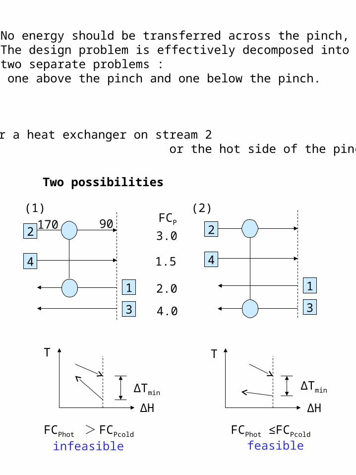
No energy should be transferred across the pinch, The design problem is effectively decomposed into two separate problems : one above the pinch and one below the pinch.
Consider a heat exchanger on stream 2 or the hot side of the pinch.
Two possibilities
4
2
1
3
FCP
3.0
1.5
2.0
4.0
90170
4
2
1
3
(1) (2)
T
ΔH ΔH
T
ΔTminΔTmin
FCPhot > FCPcold FCPhot ≤FCPcold
infeasible feasible
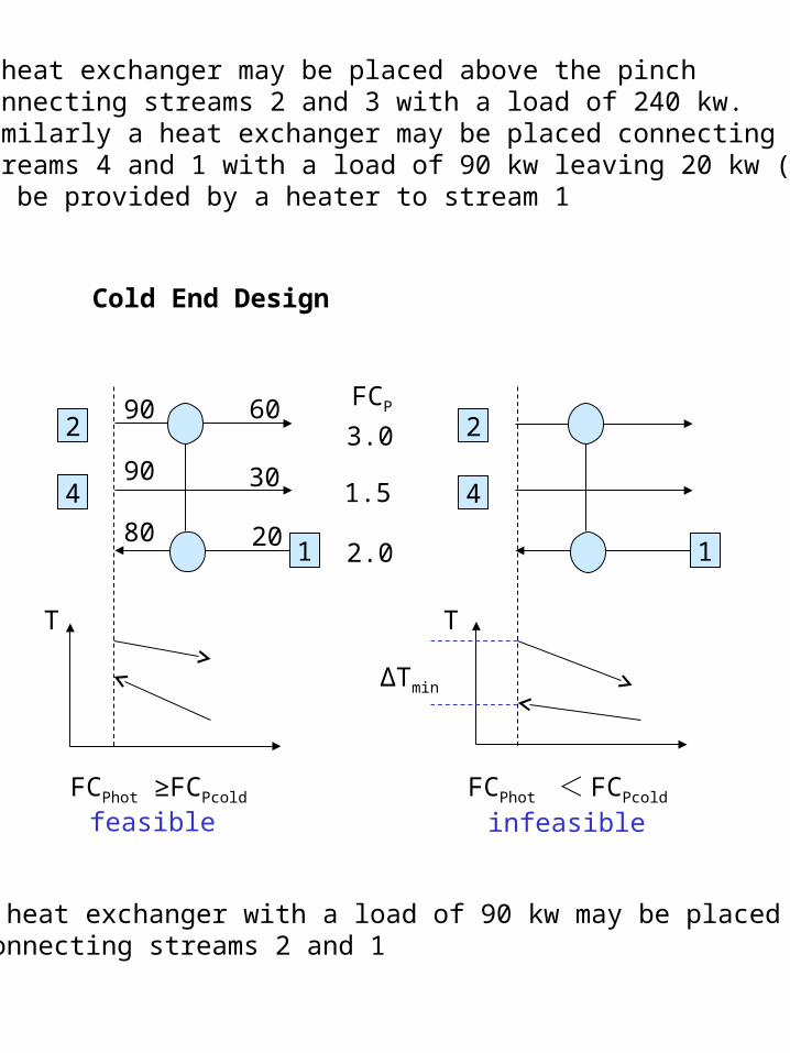
A heat exchanger may be placed above the pinch connecting streams 2 and 3 with a load of 240 kw. Similarly a heat exchanger may be placed connectingstreams 4 and 1 with a load of 90 kw leaving 20 kw (QH) to be provided by a heater to stream 1
Cold End Design
4
2
1
FCP
3.0
1.5
2.0
90
80
90
60
30
20
4
2
1
ΔTmin
T T
FCPhot ≥FCPcold FCPhot < FCPcold
infeasiblefeasible
A heat exchanger with a load of 90 kw may be placed connecting streams 2 and 1

Complete Design
2
4
1
3
H
C
170˚ 90˚ 60˚
150˚ 90˚ 70˚ 30˚
130˚20˚ 120˚ 80˚ 35˚ 60˚
20˚
90˚ 90˚ 90˚140˚
240˚
80˚
FCP
3.0
1.5
2.0
4.0
The above design achieves maximum possible energy recovery for ΔTmin = 10 ℃
1. Start at the pinch and make matches “ outwards “2. Immediately above pinch make matches that meet the requirement
3. Immediately below pinch make matches
that meet the requirement
FCPhot ≤FCPcold
FCPhot ≥FCPcold
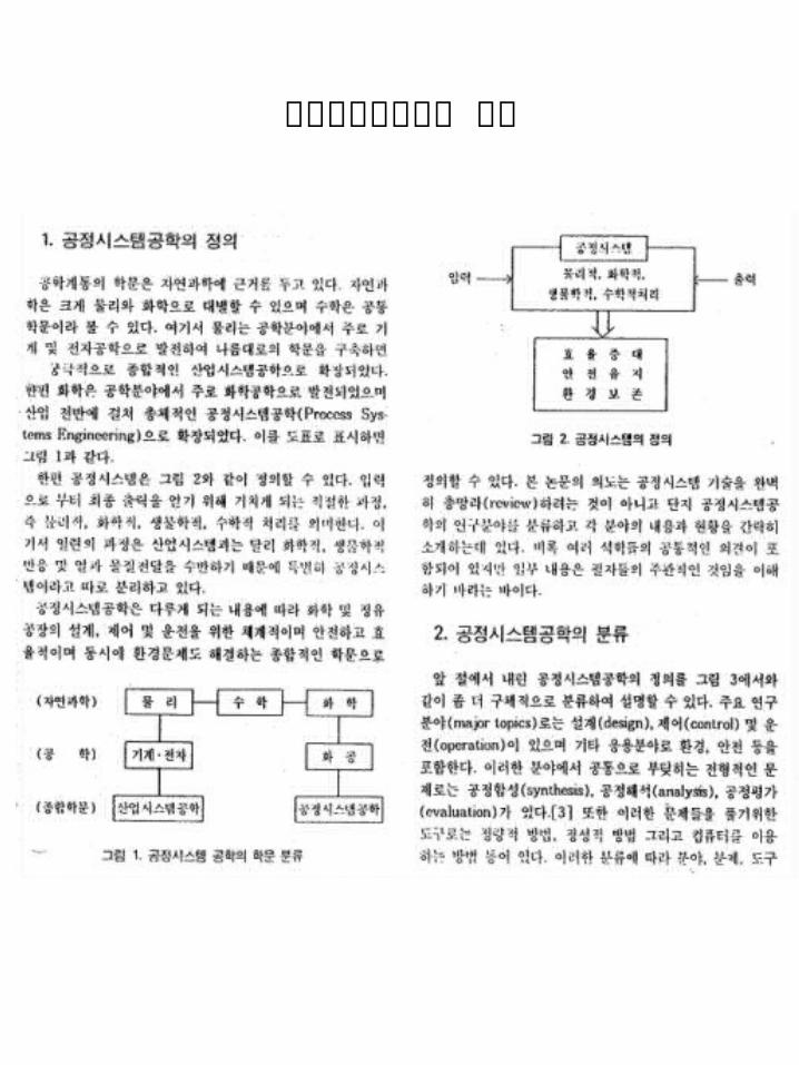
공정시스템공학의 현황