Embed Size (px)
Citation preview

FLOW INSTRUMENTATION 101
Your Logo Here
Dave Schmitt
Escondido / Irvine“Serving the Southwest’s
Instrumentation Needs Since 1987”
Dave Schmitt
Escondido / Irvine“Serving the Southwest’s
Instrumentation Needs Since 1987”

Overview – S.C. CONTROLS, INC.
Rep / Distributor / Integrator Escondido / Irvine offices Founded in 1987 Specializing in FLOW, LEVEL,
TEMPERATURE, DENSITY MEASUREMENTS
Degreed Engineers Offering solutions not just sales
Overview
Briefly describe the theory of flow measurements
Outline different types of flow meters.
Discuss advantages/ disadvantages in applications.
Present examples of instruments for measurement solutions
Questions / Answers
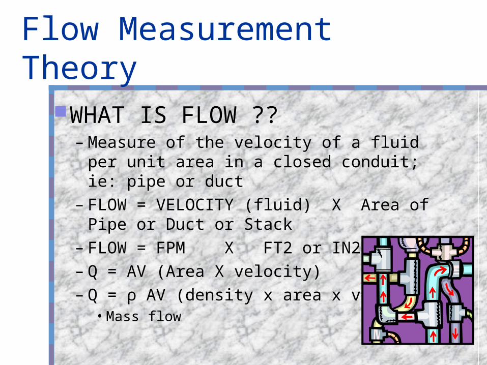
Flow Measurement Theory
WHAT IS FLOW ??– Measure of the velocity of a fluid per unit
area in a closed conduit; ie: pipe or duct– FLOW = VELOCITY (fluid) X Area of
Pipe or Duct or Stack– FLOW = FPM X FT2 or IN2– Q = AV (Area X velocity)– Q = ρ AV (density x area x vel)
• Mass flow
FLOW - In our everyday lives
Water flow meter at our home or apartment– used for billing purposes– Mechanical flow meter with local
rate and total– Relative accuracy
FLOW - In our everyday lives
Gas Flow Meter - natural gas measurement of gas used for cooking and heating– Mechanical Meter - turbine type
Liquid flow meter - Gasoline - at the local gas station where we pumped gas this morning– Positive displacement type with output
signal to electronic counter for billing
We use flow meters every day to measure fluids we use.

7
Why meter?
• Business Need• Mitigate rising energy costs • Manage energy consumption efficiently• Apportion energy costs by usage and not
square footage, creating behavior change
You cannot control what you do not measure.
8
Volumetric Flow Mass Flow Density - Liquid Density - Steam Actual vs. Standard Flow - Gas Energy Flow - Water Flow Profiles & Reynolds Number Viscosity Accuracy Repeatability Straight Run Requirements Meter Installation
Basic Flow Theory

9
Volumetric Flow (all fluids)
Q = A V
= ft
=
ft sec*
*
²ft sec³
where:
Q = volumetric flow
A = cross sectional area ( ft )
V = average fluid velocity ( )ft sec
ft sec³
²

10
Mass Flow
where:
m = mass flow ( )
= density ( )
Q = average fluid velocity ( )
A = cross sectional area ( ft )
V = average fluid velocity ( )
lbs sec
²
ft sec
ft sec
m = Q = A V
= ft
=
* **
² ft sec* *lbs ft ³
lbs sec
lbs ft ³

11
Density - Liquids
Liquids
The density of a liquid is inversely proportional to temperature:
1T
8.2877100
8.303790
8.317680
8.32970
8.337860
8.34350
8.345140
8.343632
Weight Density
Lbs/gal
Temperature
°F
WATER
12
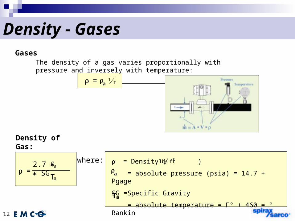
Density - Gases
where: = Density ( )
= absolute pressure (psia) = 14.7 + Pgage
SG =Specific Gravity
= absolute temperature = F° + 460 = ° Rankin
lbs ft3
Ta
a =
2.7 SG
Ta
Density of Gas:
a
Gases
= 1T
The density of a gas varies proportionally with pressure and inversely with temperature:
a

13
Density - Steam
3.7406001541.00
3.1005801324.30
2.5805601131.80
2.150540361.50
1.780520811.40
1.480500680.00
.820440381.20
0.536400247.10
0.338360152.92
0.20332089.6
Densitylbs/ft³
Temperature°F
Pressurepsia
Saturated Steam Table
0.14350080
0.15344080
0.16140080
0.17036080
0.18132080
0.03550020
0.03844020
0.03940020
0.04136020
0.04432020
Densitylbs/ft³
Temperature°F
Pressurepsia
Superheated Steam Table
Superheated steam:Saturated steam:

14
Actual vs. Standard Flow - Gas
Standard Volume Flow:
Gas flow in standard units relates the volume flow of gas to the same amount of mass flow of gas at standard conditions:
where:Q = Q
standard actual
operating
standard conditions
= specific gravity ( , at standard conditions )
= density of gas at operating pressure and temperature
= density of gas at standard conditions (at 14.7 psia, 60°F)
= standard time or
standard time
³ft unitQstandard
Qactual
operating
standard
= actual volumetric flow (ACFM, ACFH, etc…)
gas air
³m unit
SG
Actual Volume Flow:Q = V A (actual , , etc)
(actual ,hr, , etc)
* ³ft sec
³m sec
³ft min
³m sec
15
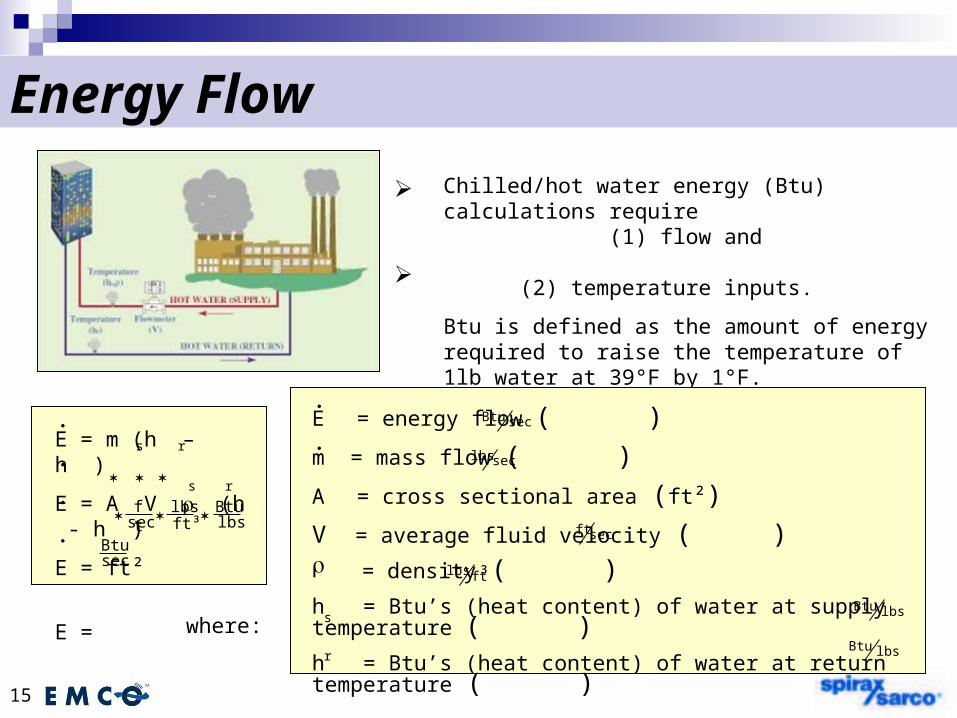
Energy Flow
Chilled/hot water energy (Btu) calculations require (1) flow and (2) temperature inputs.
Btu is defined as the amount of energy required to raise the temperature of 1lb water at 39°F by 1°F.
where:
E = energy flow ( )
m = mass flow ( )
A = cross sectional area (ft²)
V = average fluid velocity ( ) = density ( )
h = Btu’s (heat content) of water at supply temperature ( )
h = Btu’s (heat content) of water at return temperature ( )
Btu sec
lbs sec
ft sec
Btu lbs
lbs ³ft
Btu lbs
s
r
lbsft³
ftsec
E = m (h – h )
E = A V (h - h )
E = ft²
E =
s r
rs
Btulbs
Btusec
16
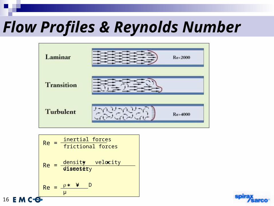
Flow Profiles & Reynolds Number
Re =
Re =
Re =
inertial forcesfrictional forces
density velocity diameterviscosity
V Dµ

17
Viscosity
Dynamic viscosity
cP (centipoise)
Kinematic Viscosity
cst (centistoke)
A measure of how freely a fluid flows:
where:V = kinematic viscosity
V = dynamic viscosity
SG = specific gravity
cP
cstV = Vcst SGcP *

18
ViscosityViscosity can be highly temperature dependent in liquids.
Steam/gas – 0.01 cP
Water – 1.0 cP
Honey – 300 cP

19
Accuracy
% of Rate or Reading
Error = % of rate measurement
% of Full Scale
Error = % of full scale full scale flow
ACCURACY +/-1%
% of Rate Max flow 1,000lb/h = 1,010 to 990 lb/hMin flow 100 lb/h = 101 to 99 lb/h
% Full scale (FS)Max flow 1,000 lb/h = 1,010 to 990 lb/hMin flow 100 lb/h = 110 (100 + 10) lb/h
to 90 (100 - 10) lb/h
i.e. +/- 10% error at minimum flow
20
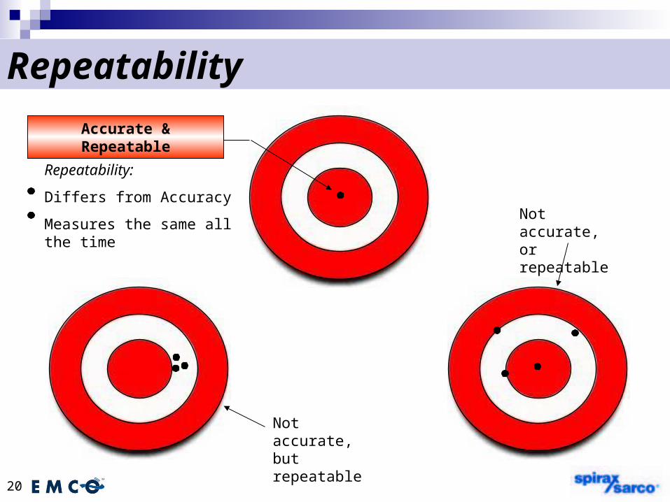
Repeatability
Not accurate, but repeatable
Not accurate, or repeatable
Accurate & Repeatable
Repeatability:
Differs from Accuracy
Measures the same all the time

21
Installation – Straight RunStraight run requirements
Minimum 10 pipe diameters upstream and 5 pipe diameters downstream required to get proper flow profile
Less straight run affects meter accuracy

22
Installation – Meter Location
Top View
Top View
Install before valve to avoid air
Vertical orientation– insure full pipe
Liquid horizontal orientation– insure full pipe
Gas & steam horizontal orientation – insure no condensate
23
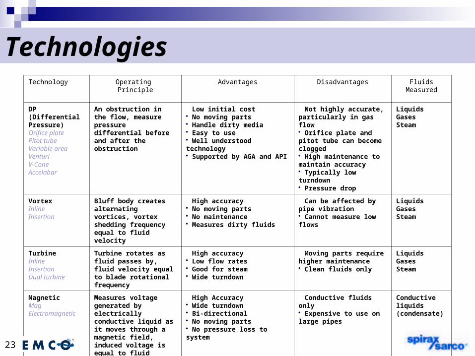
TechnologiesTechnology Operating
PrincipleAdvantages Disadvantages Fluids
Measured
DP(Differential Pressure)Orifice platePitot tubeVariable areaVenturiV-ConeAccelabar
An obstruction in the flow, measure pressure differential before and after the obstruction
Low initial cost No moving parts Handle dirty media Easy to use Well understood technology Supported by AGA and API
Not highly accurate, particularly in gas flow Orifice plate and pitot tube can become clogged High maintenance to maintain accuracy Typically low turndown Pressure drop
LiquidsGases Steam
VortexInlineInsertion
Bluff body creates alternating vortices, vortex shedding frequency equal to fluid velocity
High accuracy No moving parts No maintenance Measures dirty fluids
Can be affected by pipe vibration Cannot measure low flows
Liquids GasesSteam
TurbineInlineInsertionDual turbine
Turbine rotates as fluid passes by, fluid velocity equal to blade rotational frequency
High accuracy Low flow rates Good for steam Wide turndown
Moving parts require higher maintenance Clean fluids only
LiquidsGasesSteam
MagneticMagElectromagnetic
Measures voltage generated by electrically conductive liquid as it moves through a magnetic field, induced voltage is equal to fluid velocity
High Accuracy Wide turndown Bi-directional No moving parts No pressure loss to system
Conductive fluids only Expensive to use on large pipes
Conductive liquids (condensate)
24
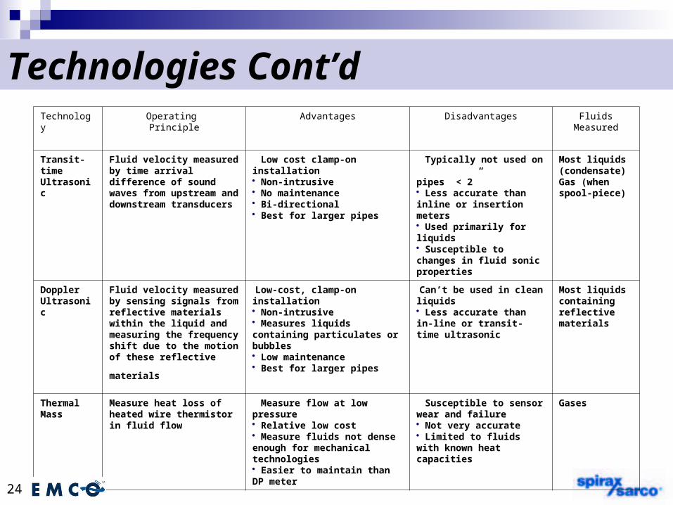
Technologies Cont’dTechnology Operating
PrincipleAdvantages Disadvantages Fluids
Measured
Transit-timeUltrasonic
Fluid velocity measured by time arrival difference of sound waves from upstream and downstream transducers
Low cost clamp-on installation Non-intrusive No maintenance Bi-directional Best for larger pipes
Typically not used on pipes < 2” Less accurate than inline or insertion meters Used primarily for liquids Susceptible to changes in fluid sonic properties
Most liquids (condensate)Gas (when spool-piece)
DopplerUltrasonic
Fluid velocity measured by sensing signals from reflective materials within the liquid and measuring the frequency shift due to the motion of these
reflective materials
Low-cost, clamp-on installation Non-intrusive Measures liquids containing particulates or bubbles Low maintenance Best for larger pipes
Can’t be used in clean liquids Less accurate than in-line or transit-time ultrasonic
Most liquids containing reflective materials
Thermal Mass
Measure heat loss of heated wire thermistor in fluid flow
Measure flow at low pressure Relative low cost Measure fluids not dense enough for mechanical technologies Easier to maintain than DP meter
Susceptible to sensor wear and failure Not very accurate Limited to fluids with known heat capacities
Gases
25
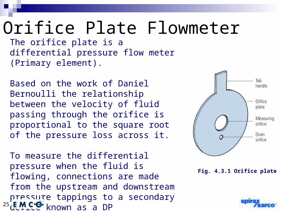
The orifice plate is a differential pressure flow meter (Primary element).
Based on the work of Daniel Bernoulli the relationship between the velocity of fluid passing through the orifice is proportional to the square root of the pressure loss across it.
To measure the differential pressure when the fluid is flowing, connections are made from the upstream and downstream pressure tappings to a secondary device known as a DP (Differential Pressure) cell.
Orifice Plate Flowmeter
Fig. 4.3.1 Orifice plate

26
Orifice Plate Flowmeter

27
Advantages: Low cost, especially on large
sizes No need for recalibration Widely accepted
Disadvantages: Poor turndown (4:1 typical) Long installations (20D to 30D) Accuracy dependant on
geometry.
Complete Customer Data Sheet:
Customer details
Fluid
Operating pressure
Operating temperature
Estimate flow rate
Line size, Pipe Schedule, Material
Flange Specification
Required package option
Orifice Plates

28
Variable orifice flow meter Line sizes 2-8” Temp up to 842°F
(450°C) Accuracy ±1.0% of
rate Gas and Steam
applications Compact installation -
6 up and 3 down Up to 100:1 turndown

29
Digital variable orifice flow meter
Line sizes 2-4” Saturated Steam ONLY 347°F (175°C) Accuracy ±2.0% of
flow Internal RTD for
Integrated mass flow measurement
Compact installation - 6 up and 3 down
Up to 50:1 turndown

30
Vortex Flowmeter
Liquid, Gas, and Steam 1-12” (25 to 300mm) Temperature up to 750°F(400°C) EZ-Logic menu-driven user
interface In-process removable sensor
(below 750psig) Fully welded design with no leak
path Optional remote mount electronic Accuracy
Liquid ±0.7% of rate Gas and Steam ±1.0% of rate
Turndown up to 20:1 Vortex

31
Insertion Vortex Meter Liquid, Gas, and Steam Model 60/60S Hot Tap, retractable Model 700 Insertion low temp, low
pressure Model 910/960 Hot tap, retractable
960-high temp up to 500°F (260°C), high pressure
Optional Temperature and/or Pressure Transmitter
Line sizes 3-80” (76 to 2032mm) No moving parts EZ-Logic menu driven user interface Accuracy
Liquid ±1.0% of rate Gas and Steam ±1.5% of flow rate
test conditions Turndown up to 20:1 VBar
32
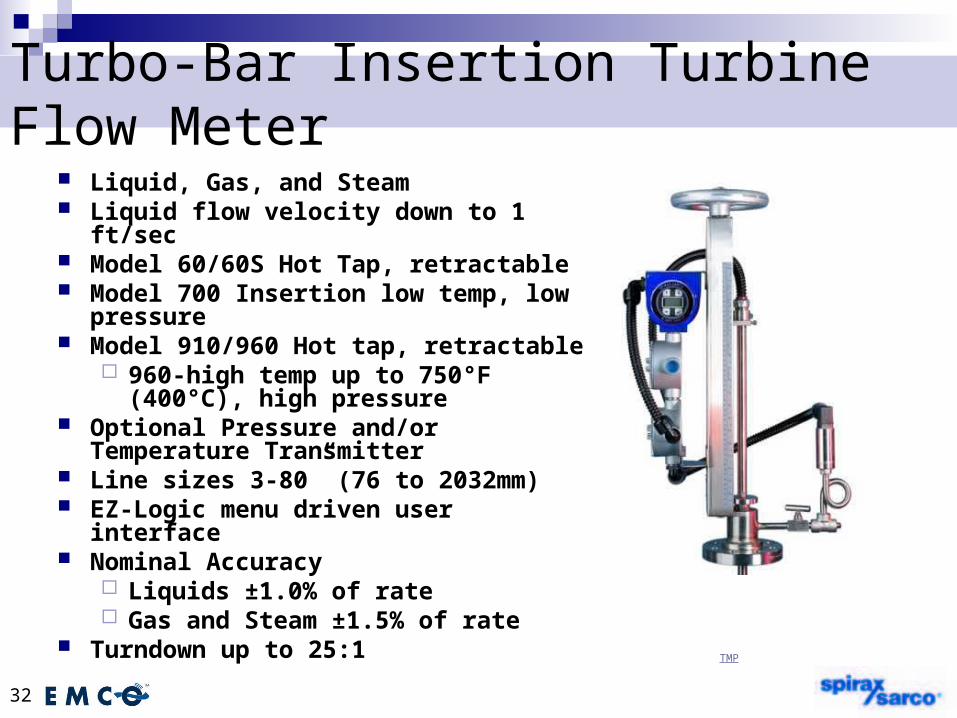
Turbo-Bar Insertion Turbine Flow Meter Liquid, Gas, and Steam Liquid flow velocity down to 1 ft/sec Model 60/60S Hot Tap, retractable Model 700 Insertion low temp, low
pressure Model 910/960 Hot tap, retractable
960-high temp up to 750°F (400°C), high pressure
Optional Pressure and/or Temperature Transmitter
Line sizes 3-80” (76 to 2032mm) EZ-Logic menu driven user interface Nominal Accuracy
Liquids ±1.0% of rate Gas and Steam ±1.5% of rate
Turndown up to 25:1TMP
33
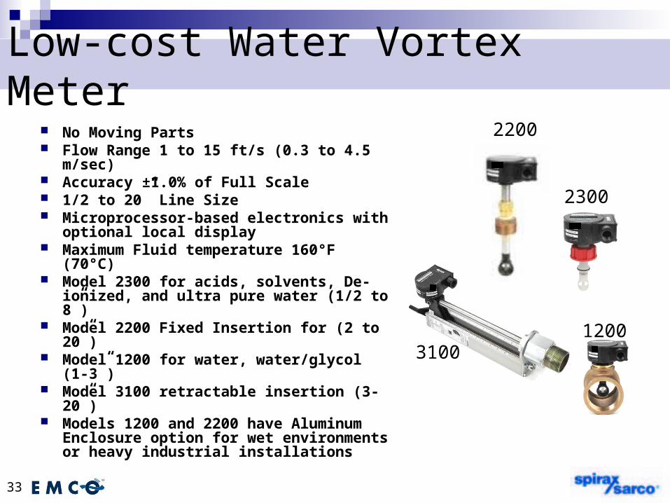
Low-cost Water Vortex Meter No Moving Parts Flow Range 1 to 15 ft/s (0.3 to 4.5 m/sec) Accuracy ±1.0% of Full Scale 1/2 to 20” Line Size Microprocessor-based electronics with
optional local display Maximum Fluid temperature 160°F
(70°C) Model 2300 for acids, solvents, De-
ionized, and ultra pure water (1/2 to 8”) Model 2200 Fixed Insertion for (2 to 20”) Model 1200 for water, water/glycol (1-3”) Model 3100 retractable insertion (3-20”) Models 1200 and 2200 have Aluminum
Enclosure option for wet environments or heavy industrial installations
1200
2200
3100
2300

34
Transit Time Ultrasonic Flowmeter
Liquid applications-Clean 2-100” (50 to 2540mm) Accuracy typically ±2.0%
of rate Non-Intrusive No wetted parts Multiple outputs available EZ-Logic menu driven user
interface Bi-Directional Transducer cable length
up to 300’Sono-Trak
35
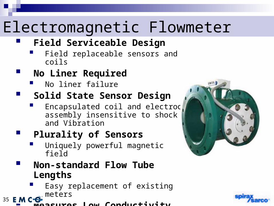
Electromagnetic Flowmeter Field Serviceable Design
Field replaceable sensors and coils
No Liner Required No liner failure
Solid State Sensor Design Encapsulated coil and electrode
assembly insensitive to shock and Vibration
Plurality of Sensors Uniquely powerful magnetic field
Non-standard Flow Tube Lengths Easy replacement of existing meters
Measures Low Conductivity Media Conductivity down to 0.8 µS/cm
THERMAL MASS FLOW METERSTHERMAL MASS FLOW METERS
FOR MEASURING GAS FLOWFOR MEASURING GAS FLOW

WHAT IS A THERMAL MASS WHAT IS A THERMAL MASS FLOW METER?FLOW METER?
It is a Meter that directly measures the It is a Meter that directly measures the Gas Mass Flow based on the principle Gas Mass Flow based on the principle of conductive and convective heat of conductive and convective heat transfer – more detail later…transfer – more detail later…
MEASURE MASS FLOW RATE MEASURE MASS FLOW RATE OR TOTALIZE COMMON GASESOR TOTALIZE COMMON GASES
Air (Compressed Air, Blower Air, Blast Furnace Air (Compressed Air, Blower Air, Blast Furnace Air, Combustion Air, Plant Air, Make-Up Air)Air, Combustion Air, Plant Air, Make-Up Air)
Natural Gas Industrial (Plant Usage, Sub-Natural Gas Industrial (Plant Usage, Sub-Metering, Boiler Efficiency, Combustion Control)Metering, Boiler Efficiency, Combustion Control)
Natural Gas Commercial & Governmental Natural Gas Commercial & Governmental (Building Automation – Reduce Energy Costs, (Building Automation – Reduce Energy Costs, LEED Credits, Meet Regulations)LEED Credits, Meet Regulations)
Digester Gas, Bio Gas, Landfill Gas (especially Digester Gas, Bio Gas, Landfill Gas (especially for EPA regulations and Carbon Credits)for EPA regulations and Carbon Credits)
Flare Gas (Vent Gas and Upset – Dual Range)Flare Gas (Vent Gas and Upset – Dual Range) Other: Propane, Nitrogen, Argon, CO2Other: Propane, Nitrogen, Argon, CO2

WHAT DO THE SENSORS WHAT DO THE SENSORS CONSIST OF?CONSIST OF?
The Sensors are RTDs, which are resistance The Sensors are RTDs, which are resistance temperature detectorstemperature detectors
They consist of highly stable reference-They consist of highly stable reference-grade platinum windingsgrade platinum windings
In fact, we use the same material that is In fact, we use the same material that is used as Platinum Resistance Standards at used as Platinum Resistance Standards at the National Institute of Standards (NIST) the National Institute of Standards (NIST)
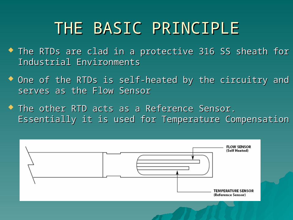
THE BASIC PRINCIPLETHE BASIC PRINCIPLE The RTDs are clad in a protective 316 SS sheath for The RTDs are clad in a protective 316 SS sheath for
Industrial EnvironmentsIndustrial Environments
One of the RTDs is self-heated by the circuitry and One of the RTDs is self-heated by the circuitry and serves as the Flow Sensorserves as the Flow Sensor
The other RTD acts as a Reference Sensor. Essentially it The other RTD acts as a Reference Sensor. Essentially it is used for Temperature Compensationis used for Temperature Compensation

SAGE PROPRIETARY SENSOR SAGE PROPRIETARY SENSOR DRIVE CIRCUITRYDRIVE CIRCUITRY
Circuitry maintains a constant overheat between Circuitry maintains a constant overheat between the Flow Sensor and Reference Sensorthe Flow Sensor and Reference Sensor
As Gas Flows by the Heated Sensor (Flow As Gas Flows by the Heated Sensor (Flow Sensor), the molecules of flowing gas carry heat Sensor), the molecules of flowing gas carry heat away from this sensor, and the Sensor cools away from this sensor, and the Sensor cools down as it loses energydown as it loses energy
Circuit equilibrium is disturbed, and Circuit equilibrium is disturbed, and momentarily the delta T between the Heated momentarily the delta T between the Heated Sensor and the Reference Sensor has changedSensor and the Reference Sensor has changed
The circuit will automatically (within 1 second), The circuit will automatically (within 1 second), replace this lost energy, by heating up the Flow replace this lost energy, by heating up the Flow Sensor so the overheat temperature is restoredSensor so the overheat temperature is restored

HOW DO THE RTDsHOW DO THE RTDs MEASURE MASS FLOW MEASURE MASS FLOW
The current required to The current required to maintain this overheat maintain this overheat represents the Mass Flow represents the Mass Flow signalsignal
There is no need for external There is no need for external Temperature or Pressure Temperature or Pressure devices devices
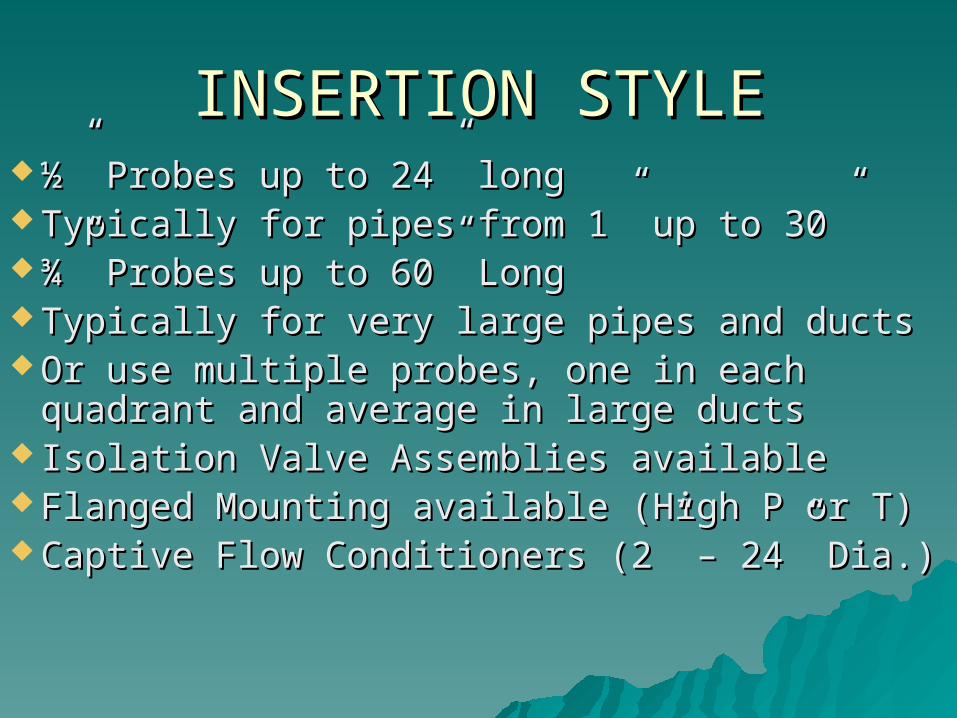
INSERTION STYLEINSERTION STYLE ½” Probes up to 24” long½” Probes up to 24” long Typically for pipes from 1” up to 30”Typically for pipes from 1” up to 30” ¾” Probes up to 60” Long¾” Probes up to 60” Long Typically for very large pipes and ducts Typically for very large pipes and ducts Or use multiple probes, one in each Or use multiple probes, one in each
quadrant and average in large ductsquadrant and average in large ducts Isolation Valve Assemblies availableIsolation Valve Assemblies available Flanged Mounting available (High P or T)Flanged Mounting available (High P or T) Captive Flow Conditioners (2” – 24” Dia.)Captive Flow Conditioners (2” – 24” Dia.)
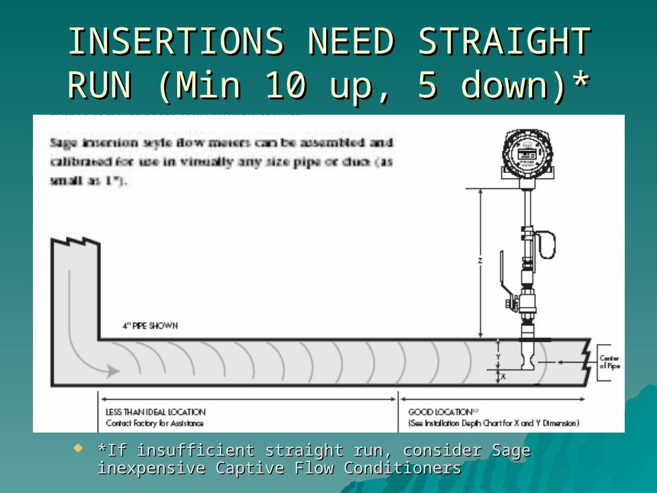
INSERTIONS NEED STRAIGHT INSERTIONS NEED STRAIGHT RUN (Min 10 up, 5 down)*RUN (Min 10 up, 5 down)*
*If insufficient straight run, consider Sage inexpensive *If insufficient straight run, consider Sage inexpensive Captive Flow ConditionersCaptive Flow Conditioners
EEEE

CAPTIVE FLOW CONDITIONERS CAPTIVE FLOW CONDITIONERS OPTIONALLY INSTALLED BY USERSOPTIONALLY INSTALLED BY USERS UPSTREAM OF INSERTION METERS UPSTREAM OF INSERTION METERS
IF INSUFFICIENT STRAIGHT RUNIF INSUFFICIENT STRAIGHT RUN

IN-LINE METERSIN-LINE METERS ¼” Flow Bodies up to ¼” Flow Bodies up to
4” NPT or Flanged4” NPT or FlangedBuilt-in Flow Built-in Flow Conditioning (Conditioning (>>1/2”)1/2”)

TYPES OF MASS FLOW METERS TYPES OF MASS FLOW METERS

REMOTE MASS FLOW METERS REMOTE MASS FLOW METERS
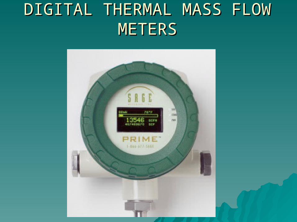
DIGITAL THERMAL MASS FLOW DIGITAL THERMAL MASS FLOW METERSMETERS
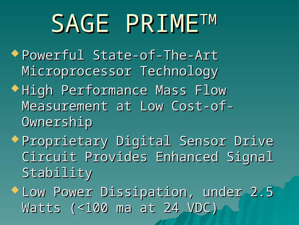
SAGE PRIMESAGE PRIMETMTM
Powerful State-of-The-Art Powerful State-of-The-Art Microprocessor TechnologyMicroprocessor Technology
High Performance Mass Flow High Performance Mass Flow Measurement at Low Cost-of-OwnershipMeasurement at Low Cost-of-Ownership
Proprietary Digital Sensor Drive Circuit Proprietary Digital Sensor Drive Circuit Provides Enhanced Signal StabilityProvides Enhanced Signal Stability
Low Power Dissipation, under 2.5 Watts Low Power Dissipation, under 2.5 Watts (<100 ma at 24 VDC)(<100 ma at 24 VDC)

SAGE PRIMESAGE PRIMETMTM
(Continued)(Continued) High Contrast Photo-Emissive Organic High Contrast Photo-Emissive Organic
LEDs (OLEDs)LEDs (OLEDs) Displays Calibration Milliwatts (mw) for Displays Calibration Milliwatts (mw) for
Ongoing Diagnostics (Zero Calibration Check)Ongoing Diagnostics (Zero Calibration Check) Modbus Compliant RS485 RTU Modbus Compliant RS485 RTU
Communications (IEEE 32 Bit Floating Point)Communications (IEEE 32 Bit Floating Point) Remote Style has Lead-Length Compensation Remote Style has Lead-Length Compensation
– Up to 1000 Feet– Up to 1000 Feet 24 VDC or 115/230 VAC Power24 VDC or 115/230 VAC Power 12 VDC Option (for Solar Energy)12 VDC Option (for Solar Energy)
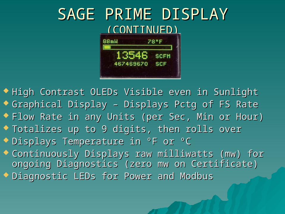
SAGE PRIME DISPLAY SAGE PRIME DISPLAY (CONTINUED)(CONTINUED)
High Contrast OLEDs Visible even in SunlightHigh Contrast OLEDs Visible even in Sunlight Graphical Display – Displays Pctg of FS RateGraphical Display – Displays Pctg of FS Rate Flow Rate in any Units (per Sec, Min or Hour)Flow Rate in any Units (per Sec, Min or Hour) Totalizes up to 9 digits, then rolls overTotalizes up to 9 digits, then rolls over Displays Temperature in ºF or ºCDisplays Temperature in ºF or ºC Continuously Displays raw milliwatts (mw) for Continuously Displays raw milliwatts (mw) for
ongoing Diagnostics (zero mw on Certificate)ongoing Diagnostics (zero mw on Certificate) Diagnostic LEDs for Power and ModbusDiagnostic LEDs for Power and Modbus

INPUT/ OUTPUTSINPUT/ OUTPUTS
24 VDC Power (draws less than 100 ma)24 VDC Power (draws less than 100 ma) 115 VAC/ 230VAC or 12 VDC Optional115 VAC/ 230VAC or 12 VDC Optional Outputs 4 – 20 ma of Flow RateOutputs 4 – 20 ma of Flow Rate Outputs 12 VDC Pulses of Totalized Flow Outputs 12 VDC Pulses of Totalized Flow (Solid (Solid
State, sourcing, transistor drive – 500ms Pulse)State, sourcing, transistor drive – 500ms Pulse)
Modbus® compliant RS485 CommunicationsModbus® compliant RS485 Communications
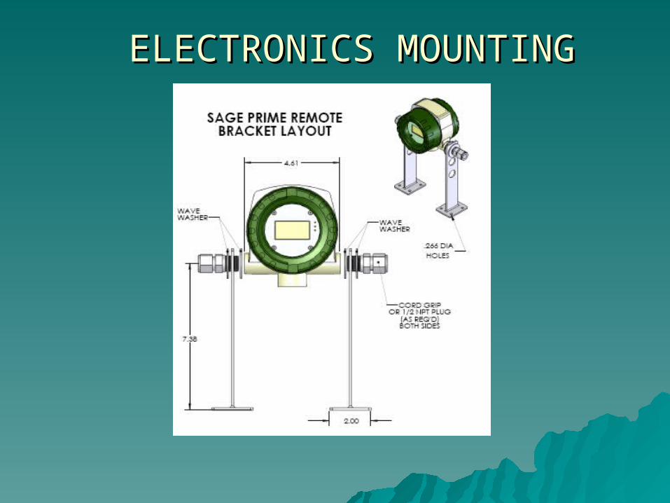
ELECTRONICS MOUNTINGELECTRONICS MOUNTING

RECONFIGURABILITYRECONFIGURABILITY
Basis MODBUS ADDRESSER Software and Basis MODBUS ADDRESSER Software and UlinxUlinx
Advanced ADDRESSER PLUSAdvanced ADDRESSER PLUS DONGLE shown below (no computer DONGLE shown below (no computer
needed)needed)

THERMAL MFM ADVANTAGESTHERMAL MFM ADVANTAGES (OVER (OVER OTHEROTHER TYPES OF TECHNOLOGIES) TYPES OF TECHNOLOGIES)
Direct Mass Flow – No need for separate Direct Mass Flow – No need for separate temperature or pressure transmitterstemperature or pressure transmitters
High Accuracy and Repeatability High Accuracy and Repeatability Turndown of 100 to 1 and resolution as Turndown of 100 to 1 and resolution as
much as 1000 to 1much as 1000 to 1 Low-End Sensitivity – Detects leaks, and Low-End Sensitivity – Detects leaks, and
measures as low as 5 SFPM!measures as low as 5 SFPM!

ADDITIONAL BENEFITSADDITIONAL BENEFITS(Pressure Independence)(Pressure Independence)
15 Data Points at 110 psig (BP), than same output, even at 0 psig (No Back Pressure)
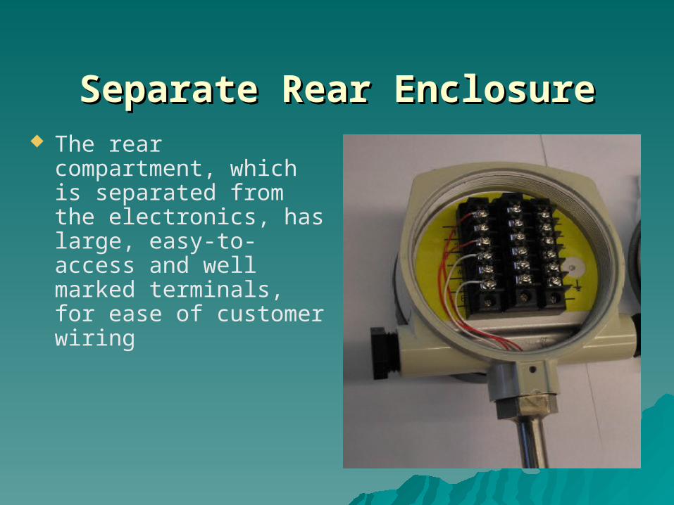
Separate Rear EnclosureSeparate Rear Enclosure The rear compartment,
which is separated from the electronics, has large, easy-to-access and well marked terminals, for ease of customer wiring

Building Automation Contractors Building Automation Contractors
Mandate to Reduce Energy Mandate to Reduce Energy ConsumptionConsumption
Needs Assessments/Portable TestingNeeds Assessments/Portable Testing Permanent Monitoring tied to Control Permanent Monitoring tied to Control
Systems - -NG, Air, N2Systems - -NG, Air, N2

Compressed AirCompressed Air
Facilities MonitoringFacilities Monitoring Sub-metering/BillingSub-metering/Billing Leak DetectionLeak Detection Energy ConservationEnergy Conservation Compressor OptimizationCompressor Optimization Performance TestingPerformance Testing

??????????????????????
QUESTIONS AND
ANSWERS
Complete solutions . . .
. . . to all your instrumentation needs !!!