Embed Size (px)
Citation preview

Parker Hannifin CorporationPneumatic DivisionRichland, Michiganwww.parker.com/pneumatics
193
Flow Controls & Accessories

Parker Hannifin CorporationPneumatic DivisionRichland, Michiganwww.parker.com/pneumatics
194
H
C
LM
D
Flow Controls & Accessories “FCM701 & FCM703” Series
H
C
LM
D
General InformationMiniature right angle flow controls provide meter out control of exhaust air from an air cylinder while providing full flow in the reverse direction. The 10-32 male thread can be used to mount directly to cylinder ports. The inlet ports are available in5-32or1/4"instanttubefittings.Theadjustmentscrewiscaptive and discourages tampering.
This compact flow control saves space and reduces the number of fittings involved in making the connection. Plumbing can be oriented 360° about the cylinder port.
Valve SpecificationsMaximum Operating Pressure ............................145 PSIG (10 bar, 1000 kPa) max.
Temperature Range* ........................... 0°F to 140°F (-18°C to 60°C)
* Ambienttemperaturesbelowfreezingrequiremoisture-freeair.Ambienttemperatures below freezing and above 180° require lubricants especially selected for suitability at these temperatures. Pneumatic valves should be used with filtered and lubricated air.
DimensionsMiniature Exhaust Flow Control FCM701 Composite Body
Part No.TubeSize
ThreadSize
C Hex (mm)
HClosed
HOpen
L MFlowDia. D
Adjusted Flow (SCFM)
Free Flow (SCFM)
FCM701-5/32-0 5/32 10-32 6 0.925 1.023 0.846 0.669 0.080 5.23 2.90
FCM701-5/32-2 5/32 1/8 7 1.000 1.083 0.935 0.708 0.100 8.41 6.32
FCM701-4-0 1/4 10-32 6 0.925 1.023 0.885 0.708 0.080 9.94 3.86
FCM701-4-2 1/4 1/8 7 1.000 1.083 0.957 0.730 0.100 10.56 5.08
FCM701-4-4 1/4 1/4 8 1.083 1.180 1.013 0.748 0.160 18.79 10.79
Knobless Miniature Exhaust Flow Control FCM703 Composite Body
Part No.Tube Size
Thread Size
C Hex (mm)
HClosed
HOpen
L MFlowDia. D
Adjusted Flow (SCFM)
Free Flow (SCFM)
FCM703-5/32-0 5/32 10-32 6 0.650 0.787 0.846 0.669 0.080 7.43 4.76
FCM703-4-2 1/4 1/8 7 0.708 0.860 0.956 0.730 0.100 12.08 5.86
FCM703-4-4 1/4 1/4 8 0.826 0.964 1.013 0.748 0.160 19.55 10.89
FCM701
FCM703
Component MaterialsBody .................................................................................. Polyamide
Mounting Thread ..................................................................... Brass
Catalog 0650-E
Miniature Right Angle Flow Control
Parker Hannifin CorporationPneumatic DivisionRichland, Michiganwww.parker.com/pneumatics
195
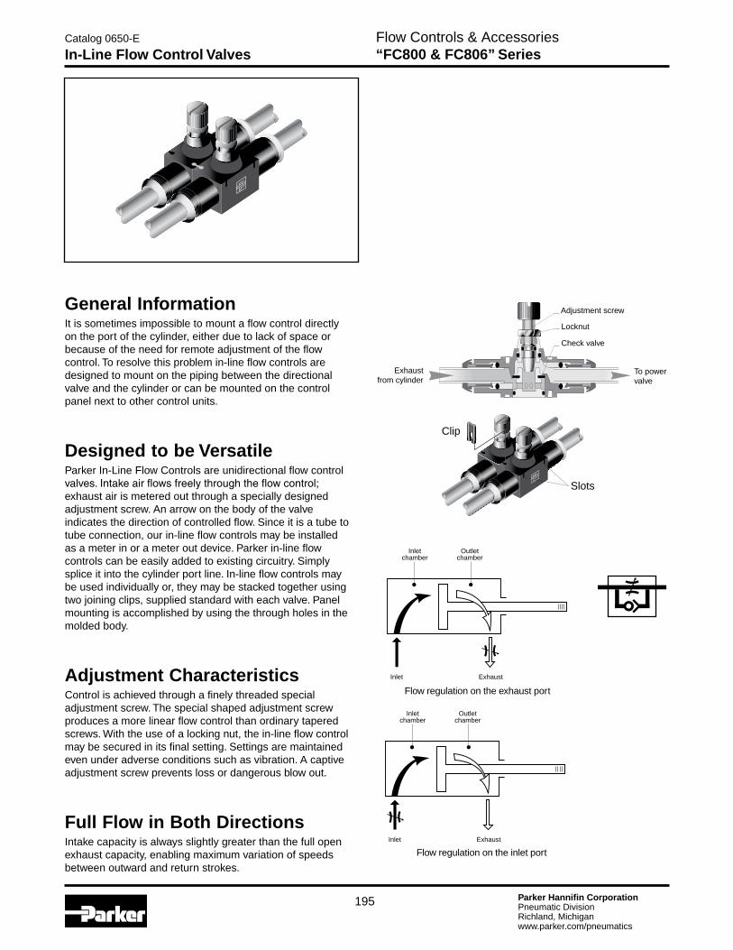
General InformationIt is sometimes impossible to mount a flow control directly on the port of the cylinder, either due to lack of space or because of the need for remote adjustment of the flow control. To resolve this problem in-line flow controls are designed to mount on the piping between the directional valve and the cylinder or can be mounted on the control panel next to other control units.
Designed to be VersatileParker In-Line Flow Controls are unidirectional flow control valves.Intakeairflowsfreelythroughtheflowcontrol;exhaust air is metered out through a specially designed adjustment screw. An arrow on the body of the valve indicates the direction of controlled flow. Since it is a tube to tube connection, our in-line flow controls may be installed as a meter in or a meter out device. Parker in-line flow controls can be easily added to existing circuitry. Simply splice it into the cylinder port line. In-line flow controls may be used individually or, they may be stacked together using two joining clips, supplied standard with each valve. Panel mounting is accomplished by using the through holes in the molded body.
Adjustment CharacteristicsControl is achieved through a finely threaded special adjustment screw. The special shaped adjustment screw produces a more linear flow control than ordinary tapered screws. With the use of a locking nut, the in-line flow control may be secured in its final setting. Settings are maintained even under adverse conditions such as vibration. A captive adjustment screw prevents loss or dangerous blow out.
Full Flow in Both DirectionsIntake capacity is always slightly greater than the full open exhaust capacity, enabling maximum variation of speeds between outward and return strokes.
Flow Controls & Accessories “FC800 & FC806” Series
Catalog 0650-E
In-Line Flow Control Valves
Clip
Slots
Inletchamber
Outletchamber
Inlet Exhaust
Flow regulation on the inlet port
Flow regulation on the exhaust port
Inletchamber
Outletchamber
Inlet Exhaust
Adjustment screw
Locknut
Exhaustfrom cylinder
Check valve
To powervalve

Parker Hannifin CorporationPneumatic DivisionRichland, Michiganwww.parker.com/pneumatics
196
FC800 In-Line Flow Control with Push-in ConnectionPart No.
1 ØD
H Min.
H Max.
L L1 K N1 N2 T OrificeH2
(mm)
FC800-5/32 5/32 1.15 1.31 1.52 .59 .47 .31 .43 .09 .12 5
FC800-4 1/4 1.54 1.74 2.11 .90 .66 .43 .66 .12 .16 8
FC800-6 3/8 2.03 2.38 2.96 1.29 .94 .62 1.01 .16 .31 14
FC800-8 1/2 2.24 2.63 3.35 1.37 1.09 .78 1.07 .16 .39 14
1 1
H
N2L1L
H2
N1K
ØT
Supplied with 2 clips
C HEX
BHEX
H
LL1
N
N1K
Advantages•AssemblyinBanks
•PanelMounting
•AllowsotherFunctionFittingstobeMountedonaCylinder
•SpaceSaving
•WeightSaving
•Flexibility
Valve SpecificationsMaximum Working Pressure ...............................................145 PSI
Operating Temperature .................................................. 5° to 150°F
Body Material ........................................High Resistance Polyamide
Adjustment Screw Material ..................................................... Brass
Dimensions
FC806 Threaded In-Line Flow Control
Part No.
Thread Size
B Hex
(mm)
C Hex
(mm)
H Closed
H Open L L1 K N N1
FC806-2 1/8 13 8 1.56 1.75 2.70 .91 .67 .67 .43
FC806-4 1/4 16 11 1.73 1.97 3.27 1.02 .73 .79 .49
FC806-6 3/8 22 14 2.05 2.40 3.82 1.30 .94 1.02 .63
FC806-8 1/2 24 14 2.26 2.66 4.76 1.38 1.10 1.08 .79
Flow Controls & Accessories “FC800 & FC806” Series
Catalog 0650-E
In-Line Flow Control Valves

Parker Hannifin CorporationPneumatic DivisionRichland, Michiganwww.parker.com/pneumatics
197
Flow Controls & Accessories PWRA & PWRE Series
Catalog 0650-E
Flow Control Valves - Features
ToPower Valve
To Cylinder
AdjustableRestriction
Non-Return
General DescriptionFlow Control – PWRE (Thermoplastic)These rugged flow controllers enhance the performance of pneumatic cylinders by precise control of piston motion in both directions. They allow full inlet flow to the cylinder while providing fine adjustment of the exhaust flow.
Right angle construction provides for convenient mounting where the cylinder is best controlled . . . at the cylinder port.
PWREThe PWRE series has a thermoplastic body with brass fittings giving lighter weight and lower profile than its metal counterpart to the left. These flow controls are supplied with instant tube fittings (fractional or metric) and NPT or BSP cylinder port fittings.
Check Valve Variable
Adjustment
Valve SpecificationsMaximum Operating Pressure ............................145 PSIG (10 bar)
Operating Temperature ........................0°to140°F*(-18°Cto60°F)
* Ambienttemperaturesbelowfreezingrequiremoisture-freeair.Ambienttemperatures below freezing and above 180° require lubricants especially selected for suitability at these temperatures. Pneumatic valves should be used with filtered and lubricated air.
Flow
No of TurnsExhaust
(Screw Open)Inlet
(Screw Closed)
12 1.8 SCFM 1.8 SCFM
PWRAThe PWRA series is made of zinc alloy, built for rugged applicationsandisavailableinsizesrangingfrom1/8"through1/2"withcylinderportfittingsineitherNPTorBSP. Tubing connections are offered either as instant fittings (fractional or metric) or threaded fittings (NPT or BSP). To prevent unwanted drift due to shock or vibration, these devices are fitted with adjustment locking nuts.

Parker Hannifin CorporationPneumatic DivisionRichland, Michiganwww.parker.com/pneumatics
198
Flow Controls & Accessories PWRA Series – Metal
Catalog 0650-E
Flow Control Valves
PWRA18••/38••PWRA14••/34••
H
L
K
4
B/2
B
∅A
H
L
K4
B/2
B
∅A
* Numberofturns(4mmAllenkey)**SCFMat90PSIwithscrewclosed
Adjustment* Flow** ØA B K H L
PWRA1468/3468 10 15.9 0.67"(17) 0.71"(18) 0.67"(17) 1.77"(45) 1.26"(32)
PWRA1488 14 23.0 0.87"(22) 0.83"(21) 0.83"(21) 2.17"(55) 1.54"(39)
PWRA1469/3469 14 26.5 0.87"(22) 0.83"(21) 0.83"(21) 2.17"(55) 1.54"(39)
PWRA1483 14 61.8 1.06"(27) 1.10"(28) 1.02"(26) 2.36"(60) 1.97"(50)
PWRA1412/3412 20 97.1 1.22"(31) 1.30"(33) 1.38"(35) 3.03"(77) 2.60"(66)
PWRA1888 10 15.9 0.67"(17) 0.71"(18) 0.67"(17) 1.77"(45) 1.44"(36.5)
PWRA1899/3899 14 31.8 0.87"(22) 0.83"(21) 0.83"(21) 2.17"(55) .71"(43.5)
PWRA1833/3833 14 68.9 1.06"(27) 1.10"(28) 1.02"(26) 2.36"(60) 2.19"(55.5)
PWRA1822/3822 20 97.1 1.22"(31) 1.30"(33) 1.38"(35) 3.03"(77) 2.48"(63)
Dimensions: Inches (mm)
PWRA3469
PWRA3833
For Cylinder Mounting(Can also be mounted in Threshold Sensor Banjo)
With Instant Tube Fittingswith Allen key adjustment and locknut
BSP NPT
Symbol CylinderPort Thread
Connectionfor Tube
CatalogNumber
CylinderPort Thread
Connectionfor Tube
CatalogNumber
1/8"6mm PWRA1468
1/8" 1/4" PWRA34688mm PWRA1488
1/4" 6mm PWRA1469 1/4" 1/4" PWRA3469
3/8" 8mm PWRA1483 — — —
1/2" 12mm PWRA1412 1/2" 1/2" PWRA3412
With Threaded Connectionwith Allen key adjustment and locknut
BSP NPT
Symbol CylinderPort Thread
ConnectionTapped Thread
CatalogNumber
CylinderPort Thread
ConnectionTapped Thread
CatalogNumber
1/8" 1/8" PWRA1888 — — —
1/4" 1/4" PWRA1899 1/4" 1/4" PWRA3899
3/8" 3/8" PWRA1833 3/8" 3/8" PWRA3833
1/2" 1/2" PWRA1822 1/2" 1/2" PWRA3822

Parker Hannifin CorporationPneumatic DivisionRichland, Michiganwww.parker.com/pneumatics
199
Flow Controls & AccessoriesPWRE Series – Thermoplastic
Catalog 0650-E
Flow Control Valves
PWRE14457
PWRE14697
PWRE1445•/1145•
PWRE14••
*SCFMat90PSIwithscrewclosed
A A
L
K
C
L C
HH
K
AdjustmentTool
AdjustmentTool
D
Adjustment # Turns Flow* ØA C D Hex. K H L
PWRE1445/14457PWRE1145/11457
PWRE14557
3mm screwdriver
12 1.8 0.43"(11) 0.16"(4) 5/16"(8) 0.28"(7.2) 0.67"(17) 0.83"(21)
PWRE1448/14487 3mmAllen key
14 10.2 0.55"(14) 0.31"(8) 9/16"(14)0.94"(23.8)
1.77"(45) 0.94"(24)
PWRE1468/14687 3mmAllen key
14 23.0 0.55"(14) 0.31"(8) 9/16"(14)0.94"(23.8)
1.77"(45) 0.94"(24)
PWRE1469/14697 4mmAllen key
18 23.0 0.63"(16)0.41"(10.5)
11/16"(17)
1.04"(26.5)
1.94"(49.3)
1.06"(27)
PWRE1483/14937 4mm Allen key
18 47.7 0.79"(20)0.45"(11.5)
7/8"(22)1.17"(29.8)
2.24"(56.8)
1.30"(33)
Dimensions: Inches (mm)
For Cylinder Mounting(Can also be mounted in Threshold Sensor Banjo)
With Instant Tube Fittingswith Allen key adjustment and fine thread friction locking
BSP NPT
Symbol CylinderPort Thread
Connectionfor Tube
CatalogNumber
CylinderPort Thread
Connectionfor Tube
CatalogNumber
M5 4mm PWRE1445 10-32 UNF5/32" PWRE14457
10-32 UNF PWRE14557
1/8"4mm PWRE1448
1/8"5/32" PWRE14487
6mm PWRE1468 1/4" PWRE14687
1/4" 6mm PWRE1469 1/4" 1/4" PWRE14697
3/8" 8mm PWRE1483 3/8" 3/8" PWRE14937
Reverse Flow M5 4mm PWRE1145 10-32UNF 5/32" PWRE11457
General InformationMiniature right angle flow controls provide meter out control of exhaust air from an air cylinder while providing full flow in the reverse direction. The M5 (10-32) male thread can be used to mount directly to cylinder ports. The inlet ports are availableinM5(10-32)maleor5/32"instanttubefitting. The adjustment screw is captive and discourages tampering.
This compact flow control saves space and reduces the number of fittings involved in making the connection. Plumbing can be oriented 360° about the cylinder port.
Valve SpecificationsMaximum Operating Pressure ............................145 PSIG (10 bar)
Operating Temperature ........................0°to140°F*(-18°Cto60°F)
* Ambienttemperaturesbelowfreezingrequiremoisture-freeair.Ambienttemperatures below freezing and above 180° require lubricants especially selected for suitability at these temperatures. Pneumatic valves should be used with filtered and lubricated air.
Component MaterialsBody .................................................................................. Polyamide
Mounting Thread ...................................................................... Brass
Flow
No of TurnsExhaust
(Screw Open)Inlet
(Screw Closed)
12 1.8 SCFM 1.8 SCFM

Parker Hannifin CorporationPneumatic DivisionRichland, Michiganwww.parker.com/pneumatics
200
Flow Controls & Accessories “3251” Series
Catalog 0650-E
Right Angle Flow Control Valves
ApplicationThe Right Angle Flow Control is an ideal solution to cylinder speed control where space is at a premium. Costly fittings, connections and piping expenses can be eliminated because the valve can rotate 360°, the piping alignment can be in any direction.The1/8"modelcanberotatedafterfinalassembly.
OperationInstall by threading male end directly into cylinder port. The free-flow and metered-flow direction is automatically predetermined. Free-flow direction is into cylinder and metered-flow is out of the cylinder. Flow is adjusted with an Allen wrench and locked with nut.
Right Angle Flow Control also available with Prestolok fittings on inlet port to accommodate 5/32 - 3/8 tube sizes. This allows for quick connection and eliminates need for separate tube fitting.
Valve SpecificationsBody .......................................................................................... Brass
Plunger ....................................................................Brass and Acetal
Seals ....................................................................................... Buna N
Temperature Range ............................ 0°F to 140°F (-18°C to 60°C)
Pressure Rating ....................................... 125 PSIG (863 kPa) max.
Shown with Threaded Inlet
Shown with Prestolok Inlet Fitting
C
AOpen
BB1
Metered Flow
FreeFlow
Model Selection Information and Dimensions
ModelNumber
Thread (NPT) Male
Thread(NPT)
Female
A B C Weight Cv
Inches mm Inches mm Inches mm oz. kg.Adjusted
FlowFree Flow
03251 0125 1/8 1/8 1.74 44 1.18 30 0.67 17 2.0 0.9 0.26 0.20
03251 0250 1/4 1/4 1.99 51 1.40 36 0.91 23 4.5 2.0 0.75 0.68
03251 0375 3/8 3/8 2.28 58 1.71 43 1.06 27 7.0 3.2 0.84 0.72
03251 0500 1/2 1/2 2.69 68 1.98 53 1.26 32 11.0 5.0 1.64 1.41
With PrestolokFittings
Thread(NPT)
TubeSize
A B1 C Weight Cv
03251 1215 1/8 5/32 1.74 44 1.18 30 0.67 17 2.0 0.9 0.19 0.16
03251 1225 1/8 1/4 1.74 44 1.18 30 0.67 17 2.0 0.9 0.28 0.22
03251 2525 1/4 1/4 1.99 51 1.40 36 0.91 23 4.5 2.0 0.51 0.44
03251 2538 1/4 3/8 1.99 51 1.40 36 0.91 23 4.5 2.0 0.62 0.53
03251 3838 3/8 3/8 2.28 58 1.71 43 1.06 27 7.0 3.2 0.78 0.65
CAUTION: If it is possible that the ambient temperature may fall below freezing, the medium must be moisture-free to prevent internal damage or unpredictable behavior.
!
Parker Hannifin CorporationPneumatic DivisionRichland, Michiganwww.parker.com/pneumatics
201
Flow Controls & Accessories “337” Series – 1/8" to 3/4" Ports
Catalog 0650-E
Micrometer Flow Control Valves
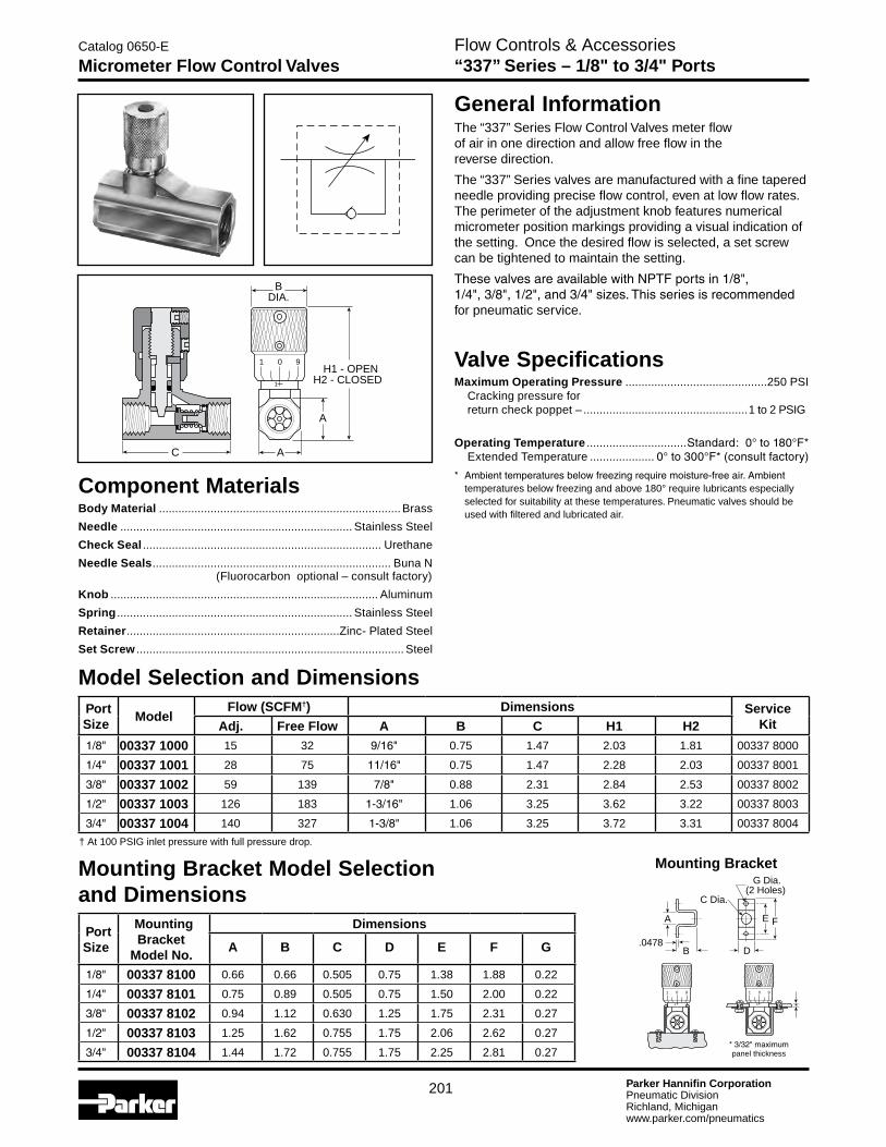
General InformationThe “337” Series Flow Control Valves meter flow of air in one direction and allow free flow in the reverse direction.
The “337” Series valves are manufactured with a fine tapered needle providing precise flow control, even at low flow rates. The perimeter of the adjustment knob features numerical micrometer position markings providing a visual indication of the setting. Once the desired flow is selected, a set screw can be tightened to maintain the setting.
ThesevalvesareavailablewithNPTFportsin1/8",
1/4",3/8",1/2",and3/4"sizes.Thisseriesisrecommendedfor pneumatic service.
Valve SpecificationsMaximum Operating Pressure ............................................250 PSI Cracking pressure for return check poppet – ...................................................1 to 2 PSIG
Operating Temperature ...............................Standard:0°to180°F* Extended Temperature .................... 0°to300°F*(consultfactory)
* Ambienttemperaturesbelowfreezingrequiremoisture-freeair.Ambienttemperatures below freezing and above 180° require lubricants especially selected for suitability at these temperatures. Pneumatic valves should be used with filtered and lubricated air.
Model Selection and DimensionsPort Size
ModelFlow (SCFM†) Dimensions Service
KitAdj. Free Flow A B C H1 H21/8" 00337 1000 15 32 9/16" 0.75 1.47 2.03 1.81 00337 8000
1/4" 00337 1001 28 75 11/16" 0.75 1.47 2.28 2.03 00337 8001
3/8" 00337 1002 59 139 7/8" 0.88 2.31 2.84 2.53 00337 8002
1/2" 00337 1003 126 183 1-3/16" 1.06 3.25 3.62 3.22 00337 8003
3/4" 00337 1004 140 327 1-3/8" 1.06 3.25 3.72 3.31 00337 8004
† At 100 PSIG inlet pressure with full pressure drop.
Mounting Bracket Model Selection and Dimensions
Port Size
Mounting Bracket
Model No.
Dimensions
A B C D E F G
1/8" 00337 8100 0.66 0.66 0.505 0.75 1.38 1.88 0.22
1/4" 00337 8101 0.75 0.89 0.505 0.75 1.50 2.00 0.22
3/8" 00337 8102 0.94 1.12 0.630 1.25 1.75 2.31 0.27
1/2" 00337 8103 1.25 1.62 0.755 1.75 2.06 2.62 0.27
3/4" 00337 8104 1.44 1.72 0.755 1.75 2.25 2.81 0.27
Component MaterialsBody Material ........................................................................... Brass
Needle ........................................................................ Stainless Steel
Check Seal .......................................................................... Urethane
Needle Seals .......................................................................... Buna N (Fluorocarbon optional – consult factory)
Knob ................................................................................... Aluminum
Spring ......................................................................... Stainless Steel
Retainer ..................................................................Zinc- Plated Steel
Set Screw ................................................................................... Steel
BDIA.
AC
H1 - OPENH2 - CLOSED
A
1
1
0 9
Mounting Bracket
*3/32"maximumpanel thickness
C Dia.
B
E
G Dia.(2 Holes)
FA
.0478D
*
1
1
0 9 1
1
0 9

Parker Hannifin CorporationPneumatic DivisionRichland, Michiganwww.parker.com/pneumatics
202
Flow Controls & Accessories “3250” Series – 1/8" to 3/4" Ports
Catalog 0650-E
Flow Control Valves
ApplicationThe “3250” Series Flow Control Valves are specifically designed to accurately meter the flow of air in one direction and allow free flow in the opposite direction. The “3250” Series Flow Control Valves are also suitable for low pressure hydraulic service.
OperationWhen air is moving in the free flow direction through the valve, it forces the poppet off its seat and unrestricted air flow is permitted.
When air is moving in the metered direction through the valve, air pressure and the force of the poppet spring causes the poppet to close. Flow must then be through the orifice that is controlled by the metering screw. Opening this screw allows moreflow;closingit,lessflow.
Flow Rating (SCFM)
Flow PathValve Port Size
1/8" 1/4" 3/8" 1/2" 3/4"
Maximum Flow in Metered Direction
70 130 220 295 420
Maximum Flow in Free Flow Direction
60 120 205 346 615
Model Selection Information and DimensionsModel
Number03250 0119 03250 0219 03250 0319 03250 0419 03250 0519
Port SizeNPTF
1/8" 1/4" 3/8" 1/2" 3/4"
Inches mm Inches mm Inches mm Inches mm Inches mm
A 1.75 45 2.33 59 2.66 68 3.11 79 3.56 90
B 1.56 40 1.97 50 2.44 62 3.06 78 3.69 94
C 0.37 9 0.44 11 0.56 14 0.75 19 0.88 22
D 0.62 16 0.75 19 1.00 25 1.25 32 1.50 38
E 0.81 21 1.09 28 1.38 35 1.63 41 2.00 51
F 0.68 17 0.94 24 1.19 30 1.38 35 1.75 44
E
F
D
A
CFULL
FLOW
ADJ
FLOW
B(Closed)
Technical SpecificationsBody .......................................................................................... Brass
Port Size ..................................................... 1/8",1/4",3/8",1/2",3/4"
Internal Components .....................................Brass, Stainless Steel
Seals ....................................................................................... Buna N
Operating Temperature ...............................Standard:0°Fto180°F ExtendedOptions:0°Fto300°F
Operating Pressures: Air .....................................................................................250 PSIG Hydraulic ..........................................................................250 PSIG
Valve will operate mounted in any position. Lock nut on metering screw prevents change in setting during operation.

Parker Hannifin CorporationPneumatic DivisionRichland, Michiganwww.parker.com/pneumatics
203
Flow Controls & Accessories “3250” Series – 1", 1-1/4" & 1-1/2" Ports
Catalog 0650-E
Flow Control Valves
ApplicationThese extra large flow control valves have been developed to provide effective flow settings for large diameter cylinders and for other similar air applications. Each valve has a fine screw adjustment allowing precise settings which are secured by a sturdy lock nut.
OperationLarge internal port passages coupled with unique soft seal poppet and inline design provide maximum full flow capacity and minimum pressure drop in the free flow direction. Their cone shaped brass metering valve will provide consistent cylinder speed by regulating cylinder exhaust.
Flow Capacity In Full Flow Direction
PortSize
(NPTF)
Max. Flow(Needle Open) Model Num-
berSCFM** Cv
1 1000 12.3 03250 1000
1-1/4 1200 13.8 03250 1250
1-1/2 1800 17.5 03250 1500
**At100PSIGinletpressurewithfullpressuredrop.
Model Selection Information and DimensionsModel Number 03250 1000 03250 1250 03250 1500
Port Size
NPTF1" 1-1/4" 1-1/2"
Inches mm Inches mm Inches mm
A 5.00 127 5.00 127 5.88 149
B 6.50 165 6.50 165 8.00 203
C 3.00 76 3.00 76 3.75 95
D 3.25 83 3.25 83 3.50 89
E 2.25 57 2.25 57 2.50 64
F .39 10 .39 10 .39 10
G 1.31 33 1.31 33 1.50 38
H 2.13 54 2.13 54 2.38 60
Technical SpecificationsBody ...........................................................................Cast Aluminum
Port Size ...................................................................1",1-1/4",1-1/2"
Internal Components .............................................Brass, Aluminum
Seals ...................................................................... Buna N, Urethane
Spring ......................................................................... Stainless Steel
Operating Temperature: Standard ...................................................................-40°F to 180°F Extended Options ................................................... -40°F to 350°F
Operating Pressures: Maximum Air ....................................................................250 PSIG
D
A
F
C
G
E
H(Hex)
FullFlow
AdjFlowB
(Closed)
Parker Hannifin CorporationPneumatic DivisionRichland, Michiganwww.parker.com/pneumatics
204
Flow Controls & Accessories “338” Series – 1/8" to 3/4" Ports
Catalog 0650-E
Needle Valves
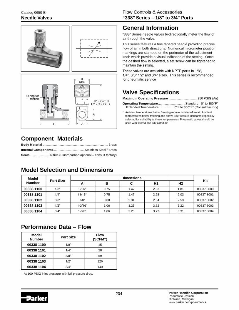
Component MaterialsBody Material ........................................................................... Brass
Internal Components ....................................Stainless Steel / Brass
Seals .......................Nitrile (Fluorocarbon optional – consult factory)
Model Selection and DimensionsModel
NumberPort Size
DimensionsKit
A B C H1 H2
00338 1100 1/8" 9/16" 0.75 1.47 2.03 1.81 00337 8000
00338 1101 1/4" 11/16" 0.75 1.47 2.28 2.03 00337 8001
00338 1102 3/8" 7/8" 0.88 2.31 2.84 2.53 00337 8002
00338 1103 1/2" 1-3/16" 1.06 3.25 3.62 3.22 00337 8003
00338 1104 3/4" 1-3/8" 1.06 3.25 3.72 3.31 00337 8004
Valve SpecificationsMaximum Operating Pressure .................................250 PSIG (Air)
Operating Temperature ...............................Standard:0°to180°F* Extended Temperature ................. 0°Fto300°F*(Consultfactory)
* Ambienttemperaturesbelowfreezingrequiremoisture-freeair.Ambienttemperatures below freezing and above 180° require lubricants especially selected for suitability at these temperatures. Pneumatic valves should be used with filtered and lubricated air.
Performance Data – FlowModel
NumberPort Size
Flow(SCFM†)
00338 1100 1/8" 15
00338 1101 1/4" 28
00338 1102 3/8" 59
00338 1103 1/2" 126
00338 1104 3/4" 140
† At 100 PSIG inlet pressure with full pressure drop.
General Information“338” Series needle valves bi-directionally meter the flow of air through the valve.
This series features a fine tapered needle providing precise flow of air in both directions. Numerical micrometer position markings are stamped on the perimeter of the adjustment knob which provide a visual indication of the setting. Once the desired flow is selected, a set screw can be tightened to maintain the setting.
ThesevalvesareavailablewithNPTFportsin1/8", 1/4",3/8"1/2"and3/4"sizes.Thisseriesisrecommendedfor pneumatic service
O-ring forfriction 1
1
0 9
C
BDIA.
A
H1 - OPENH2 - CLOSED
A

Parker Hannifin CorporationPneumatic DivisionRichland, Michiganwww.parker.com/pneumatics
205
Catalog 0650-E
Check ValvesFlow Controls & Accessories “339” Series & “3047” Series
“339” Series – 1/8" to 3/4" Ports
General Information“339” Series check valves allow free flow in one direction and provide positive checked (zero flow) in the reverse direction. ThesevalvesareavailablewithNPTFportsin1/8",1/4",3/8",1/2"&3/4"sizes.Thisseriesisrecommendedforpneumaticservice.
Valve SpecificationsMaximum Operating Pressure: 250 PSIG CrackingPressure:1to2PSIG
Operating Temperature: Standard:0°to180°F* ExtendedTemperatureOption:0°Fto300°F** Ambienttemperaturesbelowfreezingrequiremoisture-freeair.Ambient
temperatures below freezing and above 180° require lubricants especially selected for suitability at these temperatures. Pneumatic valves should be used with filtered and lubricated air.
Component MaterialsBody Material .......................................................................... Brass
Internal Components ..................................Brass / Stainless Steel / Zinc-Plated Steel
Seals ................................................................. Urethane (standard), Fluorocarbon (optional – consult factory)
Model Selection and DimensionsModel
NumberPort Size
Flow†
(SCFM)Dimensions Service
KitA B
00339 3000 1/8" 35 1.22 0.56 00337 8000
00339 3001 1/4" 75 1.34 0.69 00337 8001
00339 3002 3/8" 143 2.00 0.88 00337 8002
00339 3003 1/2" 162 2.56 1.19 00337 8003
00339 3004 3/4" 323 2.66 1.38 00337 8004
BA
B
“3047” – 1/4" Male Pipe
General Information“3047” Series check valves allow free flow in one direction and provide positive checked (zero flow) in the reverse direction.Thisvalveisavailablewithamale1/4"NPTFconnection and is recommended for pneumatic service.
Valve SpecificationsMaximum Operating Pressure: 250 PSIG CrackingPressure:1to2PSIG
Operating Temperature: Standard:0°to180°F** Ambienttemperaturesbelowfreezingrequiremoisture-freeair.Ambient
temperatures below freezing and above 180° require lubricants especially selected for suitability at these temperatures. Pneumatic valves should be used with filtered and lubricated air.
Component MaterialsBody Material ........................................................................... Brass
Internal Components ....................................Brass / Stainless Steel
Seals ..........................................................................................Nitrile
Model SelectionModel
NumberPipe
ThreadFlow†
(SCFM)
03047 0099 1/4" 30
† At 100 PSIG inlet pressure with full pressure drop.
.22 (6)Dia.
2.56(65)
13/16 Hex
35/64 Flats
Parker Hannifin CorporationPneumatic DivisionRichland, Michiganwww.parker.com/pneumatics
206
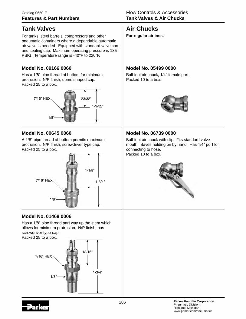
For tanks, steel barrels, compressors and other pneumatic containers where a dependable automatic air valve is needed. Equipped with standard valve core and sealing cap. Maximum operating pressure is 185 PSIG. Temperature range is -40°F to 220°F.
Tank Valves Air ChucksFor regular airlines.
Model No. 01468 0006Hasa1/8"pipethreadpartwayupthestemwhichallows for minimum protrusion. N/P finish, has screwdriver type cap. Packed 25 to a box.
Model No. 00645 0060A1/8"pipethreadatbottompermitsmaximumprotrusion. N/P finish, screwdriver type cap. Packed 25 to a box.
Model No. 05499 0000Ball-footairchuck,1/4"femaleport. Packed 10 to a box.
Model No. 09166 0060Hasa1/8"pipethreadatbottomforminimumprotrusion. N/P finish, dome shaped cap. Packed 25 to a box.
Model No. 06739 0000Ball-foot air chuck with clip. Fits standard valve mouth.Savesholdingonbyhand.Has1/4"portforconnecting to hose. Packed 10 to a box.
1-3/4"7/16"HEX
1/8"
1/8"
13/16"
1-9/32"
23/32"7/16"HEX
1/8"
1-1/8"
1-3/4"
7/16"HEX
Flow Controls & AccessoriesTank Valves & Air Chucks
Catalog 0650-E
Features & Part Numbers

Parker Hannifin CorporationPneumatic DivisionRichland, Michiganwww.parker.com/pneumatics
207
Flow Controls & Accessories “EM” Series & Muffler / Flow Controls
Catalog 0650-E
Muffler / Filters, Muffler / Flow Controls
General DescriptionMuffler / filters effectively reduce air exhaust noises to an industry accepted level with minimum flow restriction. They protect valves, impact wrenches, screw drivers and other air tools by preventing dirt and other foreign matter from entering the system. Non-corrosive. Can be cleaned with many common solvents.
SpecificationsMaximum Operating Pressure .................................250 PSIG (Air)
Operating Temperature .................................................0°to300°F*
* Ambienttemperaturesbelowfreezingrequiremoisture-freeair.Ambienttemperatures below freezing and above 180° require lubricants especially selected for suitability at these temperatures. Pneumatic valves should be used with filtered and lubricated air.
Muffler / Flow Controls General DescriptionMuffler / flow controls provide an acceptable exhaust noise level and effectively meter exhaust. Installed in valve exhaust ports, they control cylinder piston speeds throughout a wide range. The adjusting screw cannot be accidently blown out, can be locked to maintain setting. Brass and bronze construction. Clean with commonly used solvents.
SpecificationsMaximum Operating Pressure .................................250 PSIG (Air)
Operating Temperature .................................................0°to300°F*
* Ambienttemperaturesbelowfreezingrequiremoisture-freeair.Ambienttemperatures below freezing and above 180° require lubricants especially selected for suitability at these temperatures. Pneumatic valves should be used with filtered and lubricated air.
ModelNumber
PipeThread
OverallLength
HexSize
EM12 1/8" 1.00 7/16"
EM25 1/4" 1.32 9/16"
EM37 3/8" 1.54 11/16"
EM50 1/2" 1.85 7/8"
EM75 3/4" 2.29 1-1/6"
EM100 1" 2.91 1-5/16"
EM125 1-1/4" 3.25 1-11/16"
EM150 1-1/2" 3.69 2"
“EM” Series – Sintered Bronze Muffler / Filters
ModelNumber
PipeThread
OverallLength
HexSize
04502 0002 1/8" 1.15 9/16"
04504 0004 1/4" 1.42 1/2"
04506 0060 3/8" 1.49 11/16"
04508 0080 1/2" 1.77 7/8"
04512 0012 3/4" 1.98 1-1/16"
04516 0016 1" 2.15 1-5/16"

Parker Hannifin CorporationPneumatic DivisionRichland, Michiganwww.parker.com/pneumatics
208
Flow Controls & Accessories Breather Vents & “ES” Series
Catalog 0650-E
Breather Vents, Silencers
Breather Vents SpecificationsMaximum Operating Pressure ................................. 150 PSIG (Air)
Operating Temperature .................................................0°to300°F*
* Ambienttemperaturesbelowfreezingrequiremoisture-freeair.Ambienttemperatures below freezing and above 180° require lubricants especially selected for suitability at these temperatures. Pneumatic valves should be used with filtered and lubricated air.
NOTE: Breather vents should not be used as exhaust mufflers.
“ES” Series – Silencer General DescriptionThese low silhouette versions of the muffler / filter are useful where space is a problem and / or to prevent contamination. Use for vacuum relief or pressure equalization in gear boxes, oil tanks, reservoirs, etc. Non-corrosive.
The silencer is designed to give superior performance in noise control with a minimum effect on air efficiency. “Trimline” design allows location in the tightest places without extra plumbing and fittings. Fits directly into the exhaust port of more than 90% of present commercial valves. Slotted body permits rapid discharge of air without undesirable back pressure. Unique nylon screen element resists dirt buildup or clogging.
SpecificationsMaximum Operating Pressure .................................250 PSIG (Air)
Operating Temperature .................................................0°to300°F*
* Ambienttemperaturesbelowfreezingrequiremoisture-freeair.Ambienttemperatures below freezing and above 180° require lubricants especially selected for suitability at these temperatures. Pneumatic valves should be used with filtered and lubricated air.
AD
B
ModelNumber
PipeThread
OverallLength
HexSize
04702 0002 1/8" 0.44 7/16"
04704 0004 1/4" 0.63 9/16"
04706 0006 3/8" 0.75 11/16"
04708 0008 1/2" 0.88 7/8"
04712 0012 3/4" 1.00 1-1/6"
04716 0016 1" 1.31 1-5/16"
04720 0020 1-1/4" 1.41 1-11/16"
04724 0024 1-1/2" 1.50 2"
Model NumbersPipe Thread
Flow SCFM @ 100 PSIG Inlet
Dimensions
NPTF BSPT (R) A B D
ES12MC ESB12MC 1/8" 115 1.85 0.81 0.63
ES25MC ESB25MC 1/4" 129 1.85 0.81 0.63
ES37MC ESB37MC 3/8" 219 3.31 1.26 1.00
ES50MC ESB50MC 1/2" 549 3.31 1.26 1.00
ES75MC ESB75MC 3/4" 893 4.56 2.01 1.62
ES100MC ESB100MC 1" 1,013 4.56 2.01 1.62
ES125MC ESB125MC 1-1/4" 1,486 5.69 2.88 —
ES150MC ESB150MC 1-1/2" 1,580 5.69 2.88 —
General DescriptionThese low silhouette versions of the muffler / filter are useful where space is a problem and / or to prevent contamination. Use for vacuum relief or pressure equalization in gear boxes, oil tanks, reservoirs, etc. Non-corrosive.

Parker Hannifin CorporationPneumatic DivisionRichland, Michiganwww.parker.com/pneumatics
209
Ordering Information
ECS 3 *
Flow Controls & Accessories ECS Series – 1/2" & 1"
Catalog 0650-E
Air Line Muffler – Reclassifier
A
C
B
Dimensions:
Model A B C
ECS3 5.30(135 mm)
1/2"NPT
2.57(65 mm)
ECS5 7.30 (185mm)
1"NPT
2.57(65mm)
0 10 20 30 40 50 60 70 80 90 100
SCFM
0
20
40
60
80
100
120
Flow vs. Noise Level
n
❏
●
❍
n❏
●❍ 1"OpenPipe
ECS51/2"OpenPipeECS3
dBa
10 20 30 40dm3/sn
0 10 20 30 40 50 60 70 80 90 100
SCFM
0
2
4
6
8
10
Flow vs. Back Pressure
n ●
n
●
ECS3 Back PressureECS5 Back Pressure
PSID
10 20 30 40dm3/sn
.14
.28
.41
.55
.69
bar
Performance Characteristics
FeaturesThe ECS (Muffler-Reclassifier) eliminates unwanted oil mist and reduces exhaust noise from pneumatic valves, cylinders and air motors.
•99.97%OilRemovalEfficiencies
•25dBANoiseAttenuation
•1/2"NPTand1"NPT
•DisposableUnits
•ContinuousorPluggedDrainOption
•MetalRetainedConstruction
•FastExhaustTime
Improve Overall Plant EnvironmentExhaust oil mist and noise pollution have a direct impact on worker productivity.
Oil aerosol mist from lubricators and compressors is pervasive and enters the industrial plant environment through the exhaust ports of valves, cylinders and air motors. This rapidly expanding exhaust also produces sudden and excessive noise.
The ECS (Muffler-Reclassifier) is 99.97% efficient at removing the oil aerosols. The ECS also acts as a silencer to lower the dBA levels below O.S.H.A. requirements.
The result is a cleaner, quieter environment which equates to greater work productivity and safety.
OperationCompressor oils and lubricating oils are exhausted from valves, cylinders and air motors into the ECS. Oil aerosols are “coalesced” into larger droplets and gravity pulls them into the attached drain sump. The sump can then be drained manuallyorbyusinga1/4"IDplastictubedrain.Theairflowing into the ECS is also muffled or silenced as it enters the inside of the ECS and passes through the filter media into the atmosphere.
Proven TechnologyThe ECS units are constructed from the same materials that go into our oil removal coalescing filter elements.
The seamless design insures media uniformity and strength. This proven technology provides high coalescing efficiency with low pressure drop.
The filter media is supported by cylindrical perforated steel retainers both inside and out. These retainers, fully plated for excellent corrosion resistance, give the ECS units high rupture strength in either flow direction. These filters can also be used as high efficiency inlet or bypass filters for vacuum pumps, or breather elements to protect the air above critical process liquids.
ECS3 / ECS5The ECS solves two problems inherent in compressed air exhaust from valves, cylinders and air motors - oil mist removal and noise abatement.
The ECS will improve your industrial plant environment, thereby improving worker productivity.
SpecificationsMaximum Operating Temperature ............................. 125°F (52°C)
Maximum Line Pressure .................................... 100 PSIG (6.8 bar)
Engineering Level
* Willbeentered at factory.
Size
3 1/2 inch 5 1 Inch

Parker Hannifin CorporationPneumatic DivisionRichland, Michiganwww.parker.com/pneumatics
210
Features• Autodrainported1/8"topipeawayliquid.
• Drainhasmanualoverride.
• Easilyservicedwithouttool.
• 20-250PSIGrange.
• Compactsize.
SpecificationsHousing & Cap .................................................................. Aluminum
Port Threads ............................................................... 1/4"-1/2"Top 1/8"Drain
Pressure and Temperature Ratings: Metal Bowl ..................................... 20 to 250 PSIG (0 to 17.2 bar) 32°C to 175°F (0°C to 80°C)
Seals ....................................................................................... Buna N
Ordering InformationConsists of Drip Leg Drain Housing WITH Auto Drain.
Flow Controls & Accessories Features & Operation
Catalog 0650-E
Automatic Drip Leg Drain, Relief Valve
Relief ValveAutomatic Drip Leg Drain
A
B
A B
0.75 Hex 1.88 - 2.25
19 mm 47.8 - 57.2 mm
A
B
C
A B C
2.50 2.37 0.87
64 mm 60 mm 22 mm
F
C
BA
Model No. Size
06D1NA 1/4"
06D3NA 1/2"
Features• Largereliefcapacityinacompactsize.
• Lightweightaluminumconstructionwith resilient seat.
ApplicationThe RV01A1N Pop Off Relief Valve is designed to protect against excessive pressure buildup in a pneumatic circuit or system.
Operation*With the relief valve mounted in a reservoir or system, the force of system pressure at (A) is offset by the force of spring (C) acting on poppet seat (B). At pressures lower than the setting, the poppet seat (B) is held against the body at (A) effecting a seal. As pressure approaches set point, the poppet begins to vent until set point is reached, at which time the poppet seat (B) lifts off the body at (A) allowing the excess pressure to vent to atmosphere at (F). When the excess pressure has been vented, the spring (C) acts on the poppet seat (B) forcing it to seat on the body at (A), sealing off the flow of air.
SpecificationBody & Adjusting Screw .................................................. Aluminum
Locking Nut ............................................................................... Steel
Seat Nitrile
Spring ......................................................................................... Steel
Poppet ......................................................................................Plastic
Operating Temperature .......................32°F to 200°F (0°C to 93°C)
Port Threads ................................................................ 1/4 Inch Male
Relief Range ........................................ 10 to 200 PSIG (.7 to 14 bar) with standard spring. *Ref:1RV100BInstallation&ServiceInstructions
Ordering Information
RV01A1N XXX
Blank BUNA V Flurocarbon
Seals
10 -200 PSI
Parker Hannifin CorporationPneumatic DivisionRichland, Michiganwww.parker.com/pneumatics
211
Flow Controls & Accessories 130 & 134 Series
Catalog 0650-E
Relief Valves - Diaphragm Type
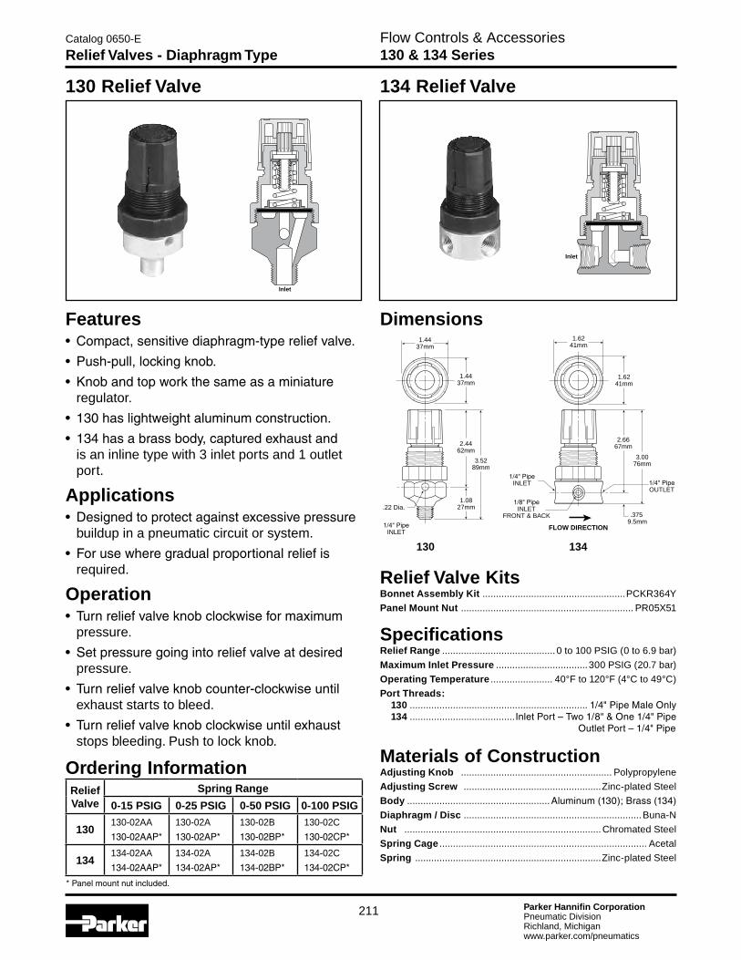
Features• Compact,sensitivediaphragm-typereliefvalve.
• Push-pull,lockingknob.
• Knobandtopworkthesameasaminiature regulator.
• 130haslightweightaluminumconstruction.
• 134hasabrassbody,capturedexhaustand is an inline type with 3 inlet ports and 1 outlet port.
Applications• Designedtoprotectagainstexcessivepressure buildup in a pneumatic circuit or system.
• Forusewheregradualproportionalreliefis required.
Operation• Turnreliefvalveknobclockwiseformaximum pressure.
• Setpressuregoingintoreliefvalveatdesired pressure.
• Turnreliefvalveknobcounter-clockwiseuntil exhaust starts to bleed.
• Turnreliefvalveknobclockwiseuntilexhaust stops bleeding. Push to lock knob.
Ordering InformationReliefValve
Spring Range
0-15 PSIG 0-25 PSIG 0-50 PSIG 0-100 PSIG
130130-02AA
130-02AAP*
130-02A
130-02AP*
130-02B
130-02BP*
130-02C
130-02CP*
134134-02AA
134-02AAP*
134-02A
134-02AP*
134-02B
134-02BP*
134-02C
134-02CP*
*Panelmountnutincluded.
Relief Valve KitsBonnet Assembly Kit .....................................................PCKR364Y
Panel Mount Nut ................................................................ PR05X51
SpecificationsRelief Range ..........................................0 to 100 PSIG (0 to 6.9 bar)
Maximum Inlet Pressure ..................................300 PSIG (20.7 bar)
Operating Temperature ....................... 40°F to 120°F (4°C to 49°C)
Port Threads: 130 .................................................................. 1/4"PipeMaleOnly 134 .......................................InletPort–Two1/8"&One1/4"Pipe OutletPort–1/4"Pipe
Materials of ConstructionAdjusting Knob ........................................................ Polypropylene
Adjusting Screw ...................................................Zinc-plated Steel
Body .....................................................Aluminum(130);Brass(134)
Diaphragm / Disc ..................................................................Buna-N
Nut .........................................................................Chromated Steel
Spring Cage ............................................................................. Acetal
Spring .....................................................................Zinc-plated Steel
130 Relief Valve
Inlet
Dimensions
130 134
2.4462mm
.22 Dia.
1/4"PipeINLET
3.5289mm
1.0827mm
1.4437mm
1.4437mm
2.6667mm
3.0076mm
.375 9.5mm
1/4"PipeINLET
1/8"PipeINLET
FRONT & BACK
1/4"PipeOUTLET
1.6241mm
1.6241mm
FLOW DIRECTION
Inlet
134 Relief Valve
Parker Hannifin CorporationPneumatic DivisionRichland, Michiganwww.parker.com/pneumatics
212
Flow Controls & Accessories “0R” Series – 1/8" thru 3/4" Ports
Catalog 0650-E
Quick Exhaust & Shuttle Valves
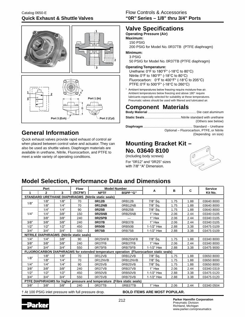
General InformationQuick exhaust valves provide rapid exhaust of control air when placed between control valve and actuator. They can also be used as shuttle valves. Diaphragm materials are available in urethane, Nitrile, Fluorocarbon, and PTFE to meet a wide variety of operating conditions.
1
3
2
Valve SpecificationsOperating Pressure (Air) Maximum: 150 PSIG 200 PSIG for Model No. 0R37TB (PTFE diaphragm)
Minimum: 3 PSIG 50 PSIG for Model No. 0R37TB (PTFE diaphragm)
Operating Temperature: Urethane:0°Fto180°F*(-18°Cto80°C) Nitrile:0°Fto180°F*(-18°Cto80°C) Fluorocarbon: 0°Fto400°F*(-18°Cto205°C) PTFE:0°Fto500°F*(-18°Cto260°C)* Ambienttemperaturesbelowfreezingrequiremoisture-freeair.
Ambient temperatures below freezing and above 180° require lubricants especially selected for suitability at these temperatures. Pneumatic valves should be used with filtered and lubricated air.
Component MaterialsBody Material ...................................................... Die cast aluminum
Static Seals .........................................Nitrile standard with urethane (Others see below)
Diaphragm ....................................................... Standard – Urethane Optional – Fluorocarbon, PTFE, or Nitrile (Depending on size)
Mounting Bracket Kit – No. 03640 8100(Including body screws)
For “0R12” and “0R25” sizes with7/8"“A”Dimension.
C
A
B
Port 1 (In)
Port 3 (Exh) Port 2 (Cyl)
12
3
Model Selection, Performance Data and DimensionsPort Flow
(SCFM†)Model Number
A B CServiceKit No.1 2 3 NPTF BSPP “G”
STANDARD URETHANE DIAPHRAGMS (Nitrile static seals)
1/8"1/8" 1/8" 70 0R12B 0RB12B 7/8"Sq. 1.75 1.88 03640 80001/8" 1/4" 70 0R12NB 0RB12NB 7/8"Sq. 1.75 1.88 03640 8000
1/4"1/4" 1/4" 90 0R25B 0RB25B 7/8"Sq. 1.75 1.88 03640 80001/4" 3/8" 150 0R25NB 0RB25NB 1"Hex 2.06 2.44 03340 01053/8" 3/8" 240 0R25PB — 1"Hex 2.06 2.44 03340 0105
3/8" 3/8" 3/8" 240 0R37B 0RB37B 1"Hex 2.06 2.44 03340 01051/2" 1/2" 1/2" 450 0R50B 0RB50B 1-1/2"Hex 2.88 3.38 03475 01093/4" 3/4" 3/4" 550 0R75B 0RB75B 1-1/2"Hex 2.88 3.38 03475 0109
NITRILE DIAPHRAGMS (Nitrile static seals)1/4" 1/4" 3/8" 90 0R25NFB 0RB25NFB 7/8"Sq. 1.75 1.88 03340 80003/8" 3/8" 3/8" 240 0R37FB 0RB37FB 1"Hex 2.06 2.44 03340 80003/4" 3/4" 3/4" 550 0R75FB 0RB75FB 1-1/2"Hex 2.88 3.38 03475 9000
FLUOROCARBON DIAPHRAGMS for extended temperature operation (Fluorocarbon static seals)
1/8"1/8" 1/8" 70 0R12VB 0RB12VB 7/8"Sq. 1.75 1.88 03650 80001/8" 1/4" 70 0R12NVB 0RB12NVB 7/8"Sq. 1.75 1.88 03650 8000
1/4" 1/4" 1/4" 90 0R25VB 0RB25VB 7/8"Sq. 1.75 1.88 03650 80003/8" 3/8" 3/8" 240 0R37VB 0RB37VB 1"Hex 2.06 2.44 03340 03191/2" 1/2" 1/2" 450 0R50VB 0RB50VB 1-1/2"Hex 2.88 3.38 03475 01203/4" 3/4" 3/4" 550 0R75VB 0RB75VB 1-1/2"Hex 2.88 3.38 03475 0120
PTFE DIAPHRAGMS for higher pressure and temperature (Fibre static seals)3/8" 3/8" 3/8" 240 0R37TB 0RB37TB 1"Hex 2.06 2.44 03340 0504
† At 100 PSIG inlet pressure with full pressure drop. BOLD ITEMS ARE MOST POPULAR.

Parker Hannifin CorporationPneumatic DivisionRichland, Michiganwww.parker.com/pneumatics
213
Flow Controls & Accessories 1/8" to 3/8" Ports
Catalog 0650-E
Shuttle Valve
Component MaterialsBody Material .................................................................... Aluminum
Internal Components ....................................................... Aluminum
Seals ..........................................................................................Nitrile
General InformationShuttle valves determine a single pneumatic output from two separate inputs. If pressure is applied to both ports simultaneously, the valve will select the port with the higher pressure.
Valve SpecificationsMaximum Operating Pressure ........................200 PSIG Maximum 3PSIGMinimum:DifferentialPressure
Operating Temperature .................................................0°to160°F*
* Ambienttemperaturesbelowfreezingrequiremoisture-freeair.Ambienttemperatures below freezing and above 180° require lubricants especially selected for suitability at these temperatures. Pneumatic valves should be used with filtered and lubricated air.
Model Selection and DimensionsModel
NumberPort Size
Dimensions
A A1 B C D E F G H J K L
N164 1001 1/8" N/A 1.62 0.81 0.62 0.31 1.00 0.281 0.312 1.00 0.75 1/8 - 27 0.219
N164 2003 1/4" 2.50 2.12 1.25 1.25 0.62 2.00 0.67 0.265 1.25 1.35 1/4 - 18 0.219
N164 3003 3/8" 2.50 2.12 1.25 1.25 0.62 2.00 0.67 0.265 1.25 1.35 3/8 - 16 0.219
Performance Data – FlowModel
NumberPortSize
Flow(Cv)
N164 1001 1/8" 0.32
N164 2003 1/4" 1.65
N164 3003 3/8" 2.02
12
3
C
F
E
G B
AA1
J
H
K(3 Ports)
L Dia.(2 Holes)
OUTLET
INLETINLET
D

Parker Hannifin CorporationPneumatic DivisionRichland, Michiganwww.parker.com/pneumatics
214
Pressure
Pressure
Pressure
Man
Reg
Pressure
Pressure
Operation 1
Operation 2
Op
erat
ion
3
Operation
A B
B
BC
A
Man
AMan
CMan
D
MAN
Man
Pressure
Man
Man
Flow Controls & Accessories Typical Applications
Catalog 0650-E
Quick Exhaust & Shuttle Valve
Rapid Retraction – Double Acting CylinderIn this circuit, air is exhausted through a Quick Exhaust Valve that is close coupled to the cap end of the cylinder. Because the Quick Exhaust Valve has a greater exhaust capacity than the four-way Control Valve, increased cylinder speed can be accomplished with a smaller and less expensive control valve.
Dual Pressure Actuation of Double Acting CylinderThis circuit utilizes a Quick Exhaust Valve and a three-way Control Valve to permit rapid extension of the cylinder at a high pressure. nder life.NOTE: Line pressure must be 3 or 4 times
greater than rod end pressure. Effective working pressure is the differential between the cap and rod end.
Bi-Directional Control of Two Double Acting CylindersThis circuit provides maximum control with a minimum of valving. A large four-way Control Valve is not needed to permit the rapid retraction of Cylinder A, as the Quick Exhaust Valve performs this function. The extension of Cylinders A and B and retraction of Cylinder B are controlled by Speed Control Valves.
Typical “Shuttle Valve” Applications
Typical “Quick Exhaust Valve” Applications
“OR” CircuitThe most common application of the Shuttle Valve is the “OR” Circuit. Here a cylinder or other work device can be actuated by either control valve. The valves can be manually or electrically actuated and located in any position.
Memory CircuitThis circuit enables continuous operation once initiated. Pressure is delivered to the circuit when Valve A is actuated. This allows pressure to pass through the shuttle valve actuating Valve B. Pressure then flows through Valve B and also the other side of the shuttle valve which holds Valve B open for continuous operation. To unlock the circuit, Valve C must be opened to exhaust the circuit and allow Valve B to return to its normally closed position.
InterlockThis circuit prevents the occurrence of a specific operation while one or another operation takes place. When either Valve A or B is actuated to perform operation 1 or 2, Valve D is shifted to the closed position and prevents operation 3 from occurring.

Parker Hannifin CorporationPneumatic DivisionRichland, Michiganwww.parker.com/pneumatics
215
Flow Controls & Accessories Air Line Accessories
Catalog 0650-E
Pressure Switch– P01909
A
OperationThe pressure switch monitors the air pressure in your pneumatic system. When the pressure in your system either drops below or exceeds the set point pressure, an electrical output is given.
Usinga0.125"(3mm)hexwrench,turntheadjustingscrew (A) clockwise to increase the pressure set point and counterclockwise to decrease the pressure setting. One complete revolution of the adjusting screw covers the complete adjustment range of 30 to 150 PSIG (2 to 10 bar).
.75(19)
2.35(59.7)
1.55(39)
.75(19)
1.52(38.6)
1(Common)
Ground
2(NormallyClosed)
3(Normally
Open)
1/4"NPT
3 (Normally Open)
2 (Normally Closed)1
(Common)
➤
➤
➤
Pressure Switch – P01909
Features:• Inlinemounting
• Dialindicatorforeasypressuresetting
• 5ampratedsnapactionmicroswitch
• HeavydutyAluminumcomponents
• Compactsize
• DIN43650HCMconnector
• IP65Rated
• Fieldadjustable30-150PSIG
• +/-2%repeatability
• Singlepole/Doublethrowswitch
SpecificationsElectrical ........................................5 AMP, 12/24VDC, 125/250VAC
Maximum Inlet Pressure ....................................300 PSIG (20 bar)
Mechanical Life ....................... 106 at standard operating conditions
Electrical Connection .............................................DIN 43650HCM
Electrical Protection ................................................................. IP65
Repeatability ......................................±2% at 70°F (20°C) Ambient
Temperature Range ....................... -40°F to 180°F (-40°C to 80°C)
Weight .................................................................... 0.13 lb. (0.06 Kg)
Materials of ConstructionDiaphragm ...............................................................................Nitrile
Housing ..............................................................Anodized Aluminum
Definitions and TerminologyRepeatability — Accuracy is the maximum allowable set point deviation of a single pressure or temperature switch under one given set of environmental and operational conditions.
Single Pole Double Throw (SPDT) Switching element — A SPDT switching element has one normally open, one normally closed and one common terminal. Three terminals mean that the switch can be wired with the circuit either normally open (NO), or normally closed (NC), or both.
Dead Band — The dead band, sometimes referred to as “differential” or “hysterisis”, is the change in pressure between actuation and deactuation set points.
Kits and AccessoriesBushing 1/4" to 3/8" ......................................................... 209P-6-4
Bushing 1/4" to 1/2" .......................................................... 209P-8-4

Parker Hannifin CorporationPneumatic DivisionRichland, Michiganwww.parker.com/pneumatics
216
Flow Controls & Accessories Air Line Accessories
Catalog 0650-E
Pressure Switch – P01908
OperationThe pressure switch monitors the air pressure in your pneumatic system. When the pressure in your system either drops below or exceeds the set point pressure, an electrical output is given.
Remove screw (A) from the top of the switch. Using a 0.125"(3mm)hexwrench,turntheadjustingscrew(B) clockwise to increase the pressure set point and counterclockwise to decrease the pressure setting, replace screw (A). Adjustment range of 25 to 100 PSIG (1.7 to 7.5 bar).
Standard electrical circuitBlack ............ CommonGreen ........... Normally ClosedRed .............. Normally Open
Definitions and TerminologyRepeatability — Accuracy is the maximum allowable set point deviation of a single pressure or temperature switch under one given set of environmental and operational conditions.
Single Pole Double Throw (SPDT) Switching element — A SPDT switching element has one normally open, one normally closed and one common terminal. Three terminals mean that the switch can be wired with the circuit either normally open (NO), or normally closed (NC), or both.
Dead Band — The dead band, sometimes referred to as “differential” or “hysterisis”, is the change in pressure between actuation and deactuation set points.
2.08(52.8)
1.58(40.1)
Ø1.10(28)
1/4"NPT
Red(Normally Open)
Green(Normally Closed)
Black(Common)
Pressure Switch – P01908
SpecificationsElectrical ........................................5 AMP, 12/24VDC, 125/250VAC
Maximum Inlet Pressure ....................................300 PSIG (20 bar)
Mechanical Life ......................................... 2x10⁶ at 75 PSIG (5 bar)
Electrical Connection ............................................18"FlyingLeads
Electrical Protection ................................................................. IP65
Repeatability ......................................±2% at 70°F (20°C) Ambient
Temperature Range ....................... -40°F to 180°F (-40°C to 80°C)
Weight ..................................................................... 0.23 lb. (0.11 Kg)
Materials of ConstructionDiaphragm ...............................................................................Nitrile
Housing ..................................................................................... Brass
Features:• Inlinemounting
• 5ampratedsnapactionmicroswitch
• Brassbody
• Compactsize
• Flyingleadselectricalconnection
• IP65Rated
• Fieldadjustable25-100PSIG
• +/-2%repeatability
• Singlepole/Doublethrowswitch
Kits and AccessoriesBushing 1/4" to 3/8" ......................................................... 209P-6-4
Bushing 1/4" to 1/2" .......................................................... 209P-8-4
A
B

Parker Hannifin CorporationPneumatic DivisionRichland, Michiganwww.parker.com/pneumatics
217
Flow Controls & Accessories Air Line Accessories
Catalog 0650-E
Mobile Pressure Switch
Mobile Pressure Switch P04159 – Normally Closed P04160 – Normally Open
Features:• InlineMounting
• 4AmpRatedSnapAction Micro Switch
• BrassBody
• CompactSize
• SpadeElectricalConnection
• FieldAdjustable15to150PSIG
• RubberBootProtection
• ±5%Repeatability@70°F(20°C)AmbientTemperature
• TemperatureRange-40°Fto220°F(-40°Cto105°C)
ApplicationsThese Pressure Switches are intended for use in mobile, general-purpose, compressed air systems. Product is suitable for all trailer air-ride systems, truck suspension systems, associated bus door systems, and electro-pneumatic operations. The performance requirements and reliability are suitable for the extreme cold weather environment of North American winters.
OperationThe pressure switch monitors air pressure and provides an electrical output when the pressure drops below or exceeds an adjustable preset pressure.
Adjustthepressureswitchusingaflatheadscrewdriver;turn adjustment screw clockwise to increase set point or counterclockwise to decrease set point.
SpecificationsSwitch Position P04159 ..................................................................Normally Closed P04160 ....................................................................Normally Open
Electrical Rating ........................................................................100VA
Electrical Life .............................................. 4 Amp in Rush @ 12VDC >2,000,000 Cycles
Maximum Inlet Pressure ........................................300 PSIG (20 bar)
Mechanical Life ....................................... >2 x 10⁶ @ 75 PSIG (5 bar)
Electrical Connection ...............................................1/4 x 1/32 Spade
Electrical Protection ........................................................Rubber Boot
Repeatability .......................................................±5% @ 70°F (20°C)
Ambient & Medium Temperature Range .....................................................-40°F to 220°F
(-40°C to 105°C)
Weight ...................................................................... 0.14 lb. (0.06 Kg)
Materials of ConstructionDiaphragm ................................................................................Kapton
Housing ...................................................................................... Brass
Adjustment Screw
1/4 NPT Thread(4M)
15/16(24)
Across Flats
0.54 (14)
2.33 (59.16)
1.30 (33)
1.58 (40.14)
1.51 (38.29)
0.36 (9.07)
Rubber Boot
Kits and Accessories Rubber Boot ............................................................................ P04161
Dimensions

Parker Hannifin CorporationPneumatic DivisionRichland, Michiganwww.parker.com/pneumatics
218
Flow Controls & AccessoriesCatalog 0650-E
Notes