Embed Size (px)
Citation preview

UNIVERSITA’ DEGLI STUDI DI MILANO
Facoltà di Scienze Matematiche, Fisiche e Naturali Dipartimento di Chimica Organica e Industriale
Doctorate School of Chemical Sciences and Technologies Course in Chemical Sciences
CHIM 06, XXIII Cycle
Flow chemistry applied to the preparation of small molecules potentially useful as therapeutic agents
PhD Student: Elena Riva Matr: R07818
Tutor: Prof. Daniele Passarella
Co-Tutors: Dr.Marisa Martinelli Dr. Anna Rencurosi Coordinator: Prof. Silvia Ardizzone
Academic Year 2009-2010

2
Index Chapter 1.Introduction .....................................................................................................4
1.1. Drug discovery process and enabling techniques.............................................5 1.2. Polymer-assisted solution-phase synthesis (PASPS)........................................7 1.3. Microwave-assisted organic synthesis (MAOS) ..............................................8 1.4. Flow chemistry .................................................................................................9
Chapter 2. Flow chemistry..............................................................................................10 2.1. Flow reactors: structure and design ................................................................11 2.2. Principles and key parameters ........................................................................14 2.3. Advantages of the flow technique ..................................................................14
2.3.1. Advantages related to the small dimensions of the channels ...................15 2.3.1.1. Higher selectivity, yield and reaction rate .........................................17 2.3.1.2. Pressure control: superheating effects ...............................................19 2.3.1.3. Accessibility of exothermic reactions .................................................20 2.3.1.4. Easy management of poorly stable intermediates ..............................21 2.3.1.5. Increased safety ..................................................................................22
2.3.2. Advantages related to the continuous nature of the process.....................23 2.3.2.1. Easy scale-up......................................................................................24 2.3.2.2. Continuous sequential steps ...............................................................26
2.3.3. Multi-phase systems .................................................................................28 2.3.3.1. Solid-liquid reactions .........................................................................28 2.3.3.2. Liquid-liquid reactions .......................................................................30 2.3.3.3. Gas-liquid reactions ...........................................................................33 2.3.3.4. Gas-liquid-solid reactions ..................................................................34
2.3.4. Combined technologies ............................................................................35 2.3.5. Conclusion................................................................................................36
Chapter 3. Flow chemistry in Medicinal Chemistry: state of the art .........................38 3.1. Introduction.....................................................................................................39
Chapter 4. Efficient continuous flow synthesis of hydroxamic acids and SAHA ......48 4.1. Flow synthesis of a collection of hydroxamic acids.......................................49 4.2. Flow synthesis of SAHA60..............................................................................53
Chapter 5. Reaction of Grignard reagents with carbonyl compounds and synthesis of Tramadol..........................................................................................................55 5.1. Addition of Grignard reagents to carbonyl compound under flow conditions...............................................................................................................................56 5.2. Flow synthesis of Tramadol72.........................................................................60 5.3. Addition of Grignard reagents to cyano and bifunctional compounds72 ........61
Chapter 6. Flow chemistry applied to the multistep-synthesis of natural products..65 6.1. Introduction.....................................................................................................66 6.2. State of the art .................................................................................................67
Chapter 7. Flow synthesis of (+)-dumetorine and natural congeners.........................72 7.1. Multistep synthesis of (+)-dumetorine............................................................73 7.2. Multistep synthesis of (+)-dumetorine natural congeners ..............................84
7.2.1. Flow synthesis of (+)-sedridine ................................................................84 7.2.1. Flow synthesis of (-)-sedamine ................................................................86
Chapter 8. Synthesis of supported catalysts for Metathesis Reactions.......................89

3
8.1. Introduction.....................................................................................................90 8.2. Synthesis of PS-supported Grubbs catalysts...................................................90 8.3. Synthesis of PEG-supported Hoveyda catalyst ..............................................93
Chapter 9. Conclusions ...................................................................................................96 Chapter 10. Synthesis of fluorescent compounds for the study of microtubules .......99
10.1. Introduction.................................................................................................100 10.2. Synthesis of fluorescent derivatives of tiocolchicine .................................100 10.3. Synthesis of fluorescent labelled MPP+ derivative ....................................104
Chapter 11. Experimental section ................................................................................108 11.1. Experimental protocol ................................................................................109 11.2. Experimental cection of chapter 4 ..............................................................110
11.2.1 General procedure for the synthesis of hydroxamic acid ......................110 11.2.2. Experimental for hydroxamic acids (compounds 2a-2j) ......................110 11.2.3. Scale-up of the synthesis of N-hydroxy-2-phenylacetamide…………112 11.2.4. Procedure for the synthesis of SAHA ..................................................113
11.3. Experimental section of chapter 5 ..............................................................114 11.3.1. General procedure for the synthesis of secondary and tertiary alcohols..........................................................................................................................114 11.3.2. Experimental for secondary and tertiary alcohols ................................115 11.3.3. General procedure for the synthesis of Tramadol ................................120 11.3.4. Procedure for the synthesis of 4-benzoylbenzonitrile ..........................121 11.3.5. General procedure for the flow addition of benzyl magnesium bromide to aldehydes and ketone in the presence of nitrile............................................122
11.4. Experimental section of chapter 7 ..............................................................123 11.4.1. Procedure for the synthesis of (+)-dumetorine.....................................123 11.4.2. Procedure for the synthesis of (-)-sedridine .........................................127 11.4.3. Procedure for the synthesis of (-)-sedamine.........................................128
11.5. Experimental section of chapter 8 ..............................................................130 11.5.1. Vinyl polystyrene supported Grubbs of 1st generation.........................130
11.5.1.1. Procedure for the synthesis of vinyl polystyrene supported Grubbs of 1st generation .................................................................................................130 11.5.1.2. Ring Closing Metathesis on model substrate 54 ............................131
11.5.2. PS-DVB Grubbs 2nd generation catalyst 58…………………………..131 11.5.2.1. Procedure for the synthesis of PS-DVB Grubbs 2nd generation catalyst...........................................................................................................131 11.5.2.2. Ring Closing Metathesis on model substrate 54 and on 48 ...........132
11.5.3. PEG-supported Hoveyda catalyst…………………………………….132 11.5.3.1. Procedure for the synthesis of PEG-supported Hoveyda catalyst .133 11.5.3.2. Flow RCM on model substrate 54 using PEG-supported Hoveyda catalyst, its recycle and reuse........................................................................136
Chapter 12. Bibliography……………………………………………………………..138

4
Chapter 1. Introduction

5
1.1. Drug discovery process and enabling techniques
The process of drug discovery involves the identification of clinical candidates, their synthesis and
characterization for therapeutic efficacy. During the last 50 years this process significantly
changed starting from an approach mostly based around chemistry through a more biological one
and finally moving to one more focused on the diseases. Today the advent of molecular biology,
coupled with the advances in screening and synthetic chemistry techniques allowed a combination
of both knowledge around the biological target and random screening. This transformation was
driven by a strategic imperative but was enabled by the impressive technological advances in
chemistry and biology.
The process of finding a new drug for a particular disease through the interaction with a chosen
target (Figure 1) usually starts with the “Hit finding” step that is accomplished by high-throughput
screening (HTS) and/or computational drug design. HTS is performed on libraries sufficiently
large and diverse to find novel chemical entities with a relative high probability. Another
important function of HTS is to show how selective the compounds are for the chosen target with
the goal of finding a molecule which will interact only with the desired target, but not with other
related targets (cross-screening).
Figure 1. Drug discovery process in the third millennium
In the hit validation stage, hits are assessed and experiments are performed to rule out non-specific
hits. The screening of related compounds is important to determine SAR (Structure-Activity
Relationships) and to establish the developability profile for interesting hits. Once they have been
validated, the “hit to lead” campaign can start, with a detailed set of criteria to be met in order to
Discovery Development
Commercialization
Registration 1
Lead Compound
3 Series
Candidate Drug 1-3
Hit Compound
<10
Therapeutic concept
Market Target selection
Target validation
Hit to Lead
Lead optimization
Preclinical development
Clinical development
Regulatory approval Hit
finding

6
initiate a lead optimization project. This includes not only activity criteria but also a range of
ADMET (Absorption, Distribution, Metabolism, Excretion, and Toxicity) properties to be
optimized. After hit validation and during the lead optimization process medicinal chemists will
attempt to use SAR to improve certain features of the lead compound:
● increase potency against the chosen target;
● reduce activity against unrelated targets;
● improve the "drug-likeness" or ADMET properties of the entire molecule.
This process will require several iterative screening runs, during which the properties of the new
molecular entities will be improved and the best balanced compounds will go forward to in vitro
and in vivo testing in the disease model of choice.
It is estimated that for every 100.000 compounds screened, about 100 hits are identified. Of these
100 hits only 1 proceeds to the lead compound stage. Between 40% and 60% of these lead
compounds fail ADMET testing. In recent years, despite the number of novel and clinically
validated targets identified from the human genome project, the number of new drug launches is
decreasing and the overall costs for the development of a drug are rising significantly.
Pharmaceutical and biotechnology companies are under a strong pressure to produce a steady
stream of innovative, well-differentiated drugs and with a reduced cost both for discovery and
development. Despite advances in technology and understanding of biological systems, drug
discovery is still a lengthy, expensive, difficult, and inefficient process with low rate of new
therapeutic discovery. Currently it takes an estimated 10-14 years to develop and market a drug
and development cost of each new molecular entity (NME) is approximately US$1.8 billion.
Different and novel technologies (related to synthesis, work-up and isolation) are now available to
produce compounds at a higher rate. The so called “Enabling Techniques” 1 have emerged in the
past decade and were studied in a large extent in academia. They can be applied now both in the
hit validation and lead optimization processes. These techniques summarize various traditional as
well as new methods which have been developed to speed up synthetic transformations and
importantly to make the workup as well as the isolation of products easier. Various successful
examples recently appeared in the literature in which different enabling techniques are combined
in order to achieve faster synthesis and/or improved work-up.

7
Figure 2. Enabling techniques
Among the most significant technical improvements, the greatest impact has been obtained by
polymer-assisted solution-phase synthesis (PASPS), microwave assisted organic synthesis
(MAOS) and, more recently, also by continuous-flow processes. These technologies have received
great attention in the literature and have demonstrated their potential for improving productivity in
organic synthesis and medicinal chemistry.
1.2. Polymer-assisted solution-phase synthesis (PASPS)
In research chemistry, during recent years (from the second part of 1980s), solid-supported
reagents and scavengers have been widely employed in organic chemistry, since they allow the
simplification of both synthetic procedures and isolation or purification steps, avoiding at the same
time the limitations of solid-phase synthesis.2 The most significant improvement, when PASPS is
compared to classical synthesis, is that work-up operations are considerably simplified and
reduced to simple filtration. The use of a large excess of reagents (often necessary to drive
reactions to completion) is then possible without requiring additional purification steps. Toxic,
noxious or hazardous reagents and their by-products can be immobilized and, therefore, not
released into the solution thereby improving their general acceptability and safety profile. Owing
to site isolation of reagents on the resin bead, species that are incompatible in solution may be
used together to achieve one-pot transformations that are not possible under classical homogenous
conditions.

8
1.3. Microwave-assisted organic synthesis (MAOS)
Since the late 1990s, MAOS has become a forefront support for rapid optimization of reactions,
for the efficient synthesis of new chemical entities, for discovering and probing new chemical
reactivity.
MAOS is mainly based on the efficient heating of materials by the microwave dielectric heating
effect (through dipolar polarization and ionic conduction).3
The use of microwave irradiation offers significant advantages:
● higher reaction temperatures by combination of microwave heating with sealed vessels;
● reduced reaction times, higher yields and cleaner reaction profiles;
● the use of lower boiling point solvents under pressure in sealed vessels;
● specific heating of strongly microwave-absorbing metal catalysts;
● more reproducible experimental conditions by accurate control of temperature and pressure
profile.
MAOS was shown to significantly improve productivity4 because it dramatically accelerates the
rate of many organic reactions (from days to hours and from hours to min), generally improving
the yields of the final products. Starting from early reports of microwave-promoted Suzuki
coupling,5 a wide variety of reactions has benefited from MAOS and organic reactivity with
microwaves has been extensively explored.6 In fact high speed microwave-assisted chemistry has
been successfully applied to many kinds of organic reactions including cycloaddition reactions,
heterocyclic synthesis, transition metal catalysed processes, solvent free reactions and almost all
chemical transformations where heating is required.
In literature there are also examples where transformations that did not work using conventional
heating were successfully achieved under microwave irradiation.7
The increase of the reaction rate often did not improve the productivity because classical methods
for work-up and purification of reaction products slow down the entire process.
Anyway MAOS may be advantageously coupled to inorganic-supported solvent-free conditions,
thus simplifying work-up procedures (in many cases the pure expected products can be obtained
directly by simple extraction, distillation or sublimation) and waste disposal.8 Similarly, the
combination of MAOS and solid-supported organic synthesis or PASPS9 can be performed.
Usually, the synthetic steps involving polymeric supports require repeated runs and longer
reaction times than the corresponding solution-phase protocols to reach high conversions.
Microwave heating again allows reduction of reaction times and improvement of the loading of

9
the functionalized solid support, employing not only traditional polystyrene supports but also
soluble polymers and fluorous phase synthesis. The main issue associated with MAOS is the
scalability of the process. Large-batch reactors,10 as well as continuous-flow mode11 have been
described. However, the scalability of microwave reactions still requires more development,
especially in the technology and engineering field.
1.4. Flow chemistry
Among “Enabling techniques”, continuous flow organic synthesis is gaining attention and is
moving from a strictly academic level to the wider research and development exploitation. The
result of this evolution is the increasing number of reactions successfully performed with this
technique and reported in the literature. More recently, thanks to the advent of commercially
available micro/meso flow reactors, pharmaceutical companies are embracing flow methodology
in drug discovery programs attracted by its potential advantages over the existing batch
techniques. Theoretical and practical benefits associated with performing reaction under
micro/meso continuous flow have been demonstrated for a number of common organic
transformations, ranging from liquid-liquid to solid-liquid-gas systems. In particular for pharma
companies, a very attractive feature of continuous-flow processes is the elimination of the risks
associated with failing to scale up a process because the reaction conditions set-up on microreactor
can be directly transferred to production scale without the need of re-optimisation, either by
running the flow-reactor for an extended time or by employing multi-channel parallel reactors
(numbering-up process)
In the framework of my PhD thesis exploring the application of the so called “Enabling
Techniques” in an organic and medicinal chemistry laboratory, my efforts were devoted to the
evaluation of the benefits that continuous flow chemistry could provide in Drug Discovery
programs and more in general to the preparation of challenging molecules potentially useful as
therapeutic agents and to the synthesis of natural products in comparison with traditional synthetic
techniques.

10
Chapter 2. Flow chemistry

11
2.1. Flow reactors: structure and design
In flow chemistry, a chemical reaction is performed in a continuously flowing stream in a network
of interconnecting channels: where they join one another, the fluids come into contact and the
reaction takes place.
Flow reactors are generally composed of the following basic components: one or more fluid
control devices which load the solutions of different reactants to the reactor section, the reactor,
that usually can be heated or cooled, in which reactions can occur under a precise control of
temperature and pressure and suitable reservoirs to collect the resulting mixture (Figure 3).
Figure 3. General scheme for a Flow Reactor
Laboratory scale flow reactors can generally be divided into two broad classes on the basis of
channels size and volume: micro- and meso-flow reactors. In general, but the distinction is not so
sharp and well defined, micro-flow reactors present channel having diameter from 10 to 1000 µm,
whereas meso-flow reactors are characterized by larger channels with diameter up to 1000 µm.12
The main difference between these two kinds of equipment is related to the shape of the reactors
and to the fabrication techniques. In particular micro-flow reactors are designed and produced with
methods coming from the field of semiconductor microelectronics, such as photolithography and
micro-patterning, and they are usually planar object with the size of a small plate, the “chip”. In
recent years, a variety of microreactors have been developed and several of them are now
commercially available. The applicability of a microreactor is defined by its size, the chemical and
physical properties of the material used for its construction, and the mode of reagent and solvent
introduction to the system. To illustrate the diversity in miniaturized reaction devices reported to
date, a small selection of microreactors is presented in Figure 4. A range of materials, including
glass, silicon, stainless steel, metals, and polymers have been used.

12
Figure 4. a-c) Stainless steel microreactors; b-e) Glass microreactors; d) Silicon-based microreactor
Meso-flow reactors are instead constructed of plastic tubing (generally the same material used for
HPLC equipments) with T or Y shaped junctions (Figure 5).
Figure 5. Meso-flow reactors (PTFE); T or Y shaped junctions
In this case the fabrication is a much more simple process that can be easily performed in a
common laboratory.13
In microreactors (the term microreactor (MR) will be used to indicate both micro and meso-flow
reactors as all the listed characteristics are applicable to both categories) the fluid behaviour is
mainly non-convective, with “laminar flow”14 and mixing determined only by diffusion. All flow
reactors need a precise control of fluids, achieved by two main techniques: hydrodynamic flow
and electrokinetic flow.15 The former, also called pressure driven flow, is usually associated with
syringe or peristaltic pumps that apply a positive pressure to the inlet of the system. The main
advantage of these devices is the broad compatibility with any solvent and any construction
material. However capillary resistance increases exponentially with decreasing channel
dimensions, making pumping almost impossible for too narrow tubing. Moreover the velocity

13
profile in hydrodynamic flow is parabolic, with faster flow at the centre of the channel and slower
flow near the walls; this can lead to non-homogeneous residence times (Figure 6).
Pressure driven flow Electroosmotic flow
Figure 6. Velocity profiles for pressure driven and electroosmotic flow
The alternative electrokinetic flow is associated with the application of a potential difference at the
ends of the system. The first consequence of this is the direct movement of ions in solution toward
the electrode of opposite charge. The second component of electrokinetic flow, electroosmotic
flow, arises from the electrical double layer that is formed on channels with charged surfaces. At
neutral to basic pH, glass and silica surfaces bear a negative charge due to partial ionization of
surface hydroxyl groups. In response to the negative surface charge, positive species in the
solution form a double layer near the surface of the channel. When an electric potential is applied
between the channel ends, the mobile positive ions migrate toward the negative electrode and
viscous drag between the moving ions and the rest of the solution causes net flow of the fluid
toward the negative electrode (Figure 7).
The velocity of electroosmotic flow is linearly proportional to the applied voltage, allowing
precise fluid handling. In this case the velocity profile is nearly flat across the channel, leading to
greatly reduced dispersion of reagents if compared to hydrodynamic flow. Unfortunately, the use
of electroosmotic flow is restricted to polar solvents such as water, methanol, acetonitrile,
dimethylformamide and tetrahydrofuran and to device materials that develop surface charges such
as glass, silicon and treated PDMS (Polydimethylsiloxane).
Figure 7. Electroosmotic flow

14
During the last years a good number of laboratory scale devices were commercialized. Although
most of the basic features described in this paragraph are present in all cases, different other
characteristics were introduced by producers to give the broadest set of applications to the final
user: the possibility to use solid catalyst or polymer-supported reagents, gaseous reagents (e.g. for
hydrogenations and carbonylations) and more reactors in parallel or in series. Some examples in
the literature reported the use of more complex devices, where two or more different techniques
were joined to exploit their peculiar advantages; in particular examples of microwave flow
reactors and of photochemical flow reactors.16
2.2. Principles and key parameters
In batch processes the reaction stoichiometry is defined as the ratio among the moles of reactants
while, in flow process, it depends both from the ratio of the reactant concentration and from their
flow rate. For this reason the flow system is quite more flexible as concentrations and flow rates
can vary in an independent way to find the optimal conditions.
Reaction time in a flow process is defined as the Residence Time (RT) and is determined by the
ratio between the reactor volume and the total flow rate.
RT (min) = Reactor Volume (mL) / Total Flow Rate (mL/min)
The amount of synthesized product per hour, called Output, is not related to the classical concept
of batch scale, but it is instead defined by a relation among the flow rate, concentration, molecular
weight of the product and the reaction yield.
OUTPUT (g/h) = Flow Rate (mL/min) x Conc (mmol/mL) x MW (g/mol) x Yield (%) x 0.0006
2.3. Advantages of the flow technique
The main advantages associated with the flow processes performed in microreactors can be
comprised in two broad classes.
The first one is associated with the small dimensions of the channels and includes the precise
control of the reaction conditions, the efficient mass and heat transfer, the possibility of working
under superheating conditions. The second aspect is related to the continuous nature of the process
and includes the simplicity in reaction scale-up, the possibility of performing sequential synthetic
steps with independent control of reaction conditions, the possibility of introducing in-line

15
purification by means of supported scavengers or sorbents and the possibility of interfacing the
reactor with in-line analysis devices for real time monitoring.17
The next paragraphs will be dedicated to illustrate these different aspects through the discussion of
literature examples.
2.3.1. Advantages related to the small dimensions of the channels
In the classical batch reactors, such as round-bottom flasks, the control of heat and mass
distribution is generally achieved by mechanical stirring. In most cases, however, not
homogeneous temperatures and mixing are obtained with the formation, in connection with reactor
geometry, of concentration gradients and hot spots that can lead to poor yields and low reaction
selectivity.
On the other hand microreactors assure a rapid and efficient mixing of reagents because of the
continuous and controlled addition of small volumes of reagents, reducing up to milliseconds the
time required to obtain a homogeneous solution, avoiding the formation of hot spots.18
An example of this advantage is shown in the simulation of the neutralization reaction
(HCl/NaOH) performed in batch and in a flow reactor (Figure 8).
The figure shows the concentration distribution in a MR and illustrates its efficient mixing
properties. The compound distribution in batch system is less homogeneous than in a MR and
provides the formation of hot spots.
Batch synthesis:
Concentration equivalent: 0.8 (blue)-
1.0 (green)-1.2 (red). Formation of
hot spots
Flow synthesis:
Reagent A injected in a flow stream
of B (red); green color means mixture
1:1 of the two reagents.
Figure 8. Neutralization reaction of HCl with NaOH

16
The temperature is another important parameter for obtaining good result in a reaction. Also in this
case, the small dimension of the channels permits an efficient heat transfer.
Batch synthesis
Flow synthesis: Temperature: 293 K
(blu) 298 K (green) 303 K (red)
Figure 9. Neutralization reaction of HCl with NaOH
This aspect is underlined in Figure 9 where the temperature distributions for a neutralisation
reaction (HCl and NaOH) in a batch vessel and in a channel are simulated.
In MR the average distances from the reagents flow to the heat exchanging walls of microreactors
are small. Heat exchange is driven similarly by a steep temperature gradient. At every point along
the flow channel concentration and temperature gradients are stable. These stable gradients
provide better control of reaction conditions compared to conventional synthesis. In fact the
temperature transfer in a multi-m3 batch vessel is more difficult than in a MR, hence, temperatures
are widely fluctuating within the vessel.
The second characteristic of microreactors is the high surface-to-volume ratio, also called specific
surface area. This high specific surface area is directly correlated with a high heat-exchanging
efficiency, allowing for fast heating and cooling. A qualitative distribution of the inner
temperature of a generic reaction, both in a microreactor and in a classical batch reactor is shown
in Figure 10a.19

17
Figure 10. Temperature distribution (a) and its correlation with synthetic pathway (b)
The higher heat transfer capacity of the microreactor is able to avoid that the process temperature
moves away from the set one. On the contrary, in a classical reactor, the range of temperature
around the set parameter is broader, mainly because of the lower specific surface area and mixing
issue. This different distribution may influence the route of the synthetic process.
Figure 10b shows a schematic correlation between reaction temperature and synthetic pathway;
potential energy profile is related to reaction temperature along the reaction coordinate and in
passing through transition states.
Reaction is shown to proceed from the conversion of starting material A to product B; the
formation of B is favoured if the activation energy provided by the reaction is limited, presenting a
maximum in correspondence with the set temperature (transition state B’). A side reaction profile
is also possible; it requires higher activation energy (transition state C’) and affords the by-product
C.
Whereas the batch reactor’s broad temperature distribution allows the production of the undesired
by-product C, the narrow temperature distribution in the MR restricts the reaction to the target
product B.
Different examples from the literature can help to better understand these aspects.
2.3.1.1. Higher selectivity, yield and reaction rate
Pennemann20 benchmarked some classical organic reactions performed both in micro and batch
reactors. Gathering simple literature examples, the authors highlighted the advantages of the flow
reactors, mainly in terms of reduction of reaction times from hour-long processes to procedure
displaying very short residence times. However the success of these processes was often reached

18
by a significant changing of the experimental protocol to adapt reactions to the needs of the flow
reactor engineering. Representative examples are summarized in Scheme 1. The first example is a
coupling reaction of the appropriately protected β-alanine reactants, using both DCC (dicyclohexyl
carbodiimide) as coupling agent and direct substitution on preactivated carboxylic acid.21 The
second one is a Suzuki coupling catalyzed by immobilized palladium on silica.22 The last reaction
is a 1,4-addition of enolates of 1,3-diketones to Michael acceptors using organic base.23
FmocHN OX
O H2N ODmab
O
DMFFmocHN N
H
O O
ODmab
1a. X = H, coupling agent: DCC1b. X = PFP
1.
Br CN Ph CN
PhB(OH)2Pd/SiO2
THF/H2O2.
Ph
O OCOOEt
DIPEA Ph
O O
COOEt
3.EtOH
Scheme 1. Organic reactions performed in micro (MR) and batch reactors
The comparison of the results is reported in Table 1. These data demonstrate the potentiality of the
microreactors of maintaining high conversions drastically reducing the reaction times.
MR Batch reactor
Reaction 1a
Reaction time 20 min 24 h
Conversion up to 93% 92%
Reaction 1b
Reaction time 20 min 120 h
Conversion 100% 60%
Reaction 2
Reaction time 6 s 8 h
Conversion 68% 60%

19
Reaction 3
Reaction time 20 min 24 h
Conversion 100% 89% Table 1. Comparison of results for the reactions listed in Scheme 1
2.3.1.2. Pressure control: superheating effects
In batch chemistry the highest reaction temperature depends by the boiling point of the used
solvent.
In flow reactors, as in the case of microwave assisted synthesis, working under pressure control
permits to perform reactions at temperature higher than the solvent boiling point.
Through opportune back-pressure regulators, lower boiling point solvents may be used in a wider
range of temperatures, avoiding, where not strictly necessary, high boiling solvents and thus
simplifying the reaction work-up. One example of the application of “superheating” condition was
described by Ley. 24
Scheme 2. Heck coupling in continuous flow
A series of Heck coupling were performed in continuous flow condition using ligand-free
monolithic palladium(0) nanoparticles in DMF as solvent by an automatic reactor (Scheme 2). The
couplings proceeded rapidly at 130°C and DMF, chosen for its high boiling point, was then easily
replaced by more benign ethanol. This solvent in superheating conditions under pressure,
maintained high yields as reported in Table 2.
The problem of the leaching of the supported metal into solution was solved using thiourea-based
metal scavenger resin that permits to limit Pd levels < 5 ppm in the isolated products.
20
R1 R2 Solvent Yield
4-C(O)CH3 2-Pyridinyl DMF 87%
4-C(O)CH3 2-Pyridinyl EtOH 86%
4-COOEt -COOtBu EtOH 87%
4-COOEt Phenyl EtOH 88%
3-CN 2-Pyridinyl EtOH 85% Table 2. Heck coupling of various substrates in different solvents
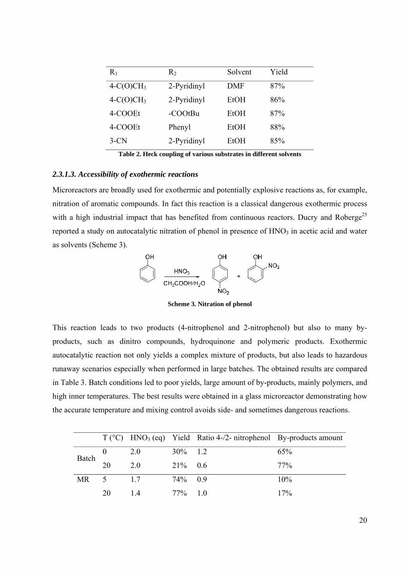
2.3.1.3. Accessibility of exothermic reactions
Microreactors are broadly used for exothermic and potentially explosive reactions as, for example,
nitration of aromatic compounds. In fact this reaction is a classical dangerous exothermic process
with a high industrial impact that has benefited from continuous reactors. Ducry and Roberge25
reported a study on autocatalytic nitration of phenol in presence of HNO3 in acetic acid and water
as solvents (Scheme 3).
Scheme 3. Nitration of phenol
This reaction leads to two products (4-nitrophenol and 2-nitrophenol) but also to many by-
products, such as dinitro compounds, hydroquinone and polymeric products. Exothermic
autocatalytic reaction not only yields a complex mixture of products, but also leads to hazardous
runaway scenarios especially when performed in large batches. The obtained results are compared
in Table 3. Batch conditions led to poor yields, large amount of by-products, mainly polymers, and
high inner temperatures. The best results were obtained in a glass microreactor demonstrating how
the accurate temperature and mixing control avoids side- and sometimes dangerous reactions.
T (°C) HNO3 (eq) Yield Ratio 4-/2- nitrophenol By-products amount
0 2.0 30% 1.2 65% Batch
20 2.0 21% 0.6 77%
5 1.7 74% 0.9 10% MR
20 1.4 77% 1.0 17%
21
55 1.7 65% 0.9 23% Table 3. Nitration of phenol in MR and batch conditions
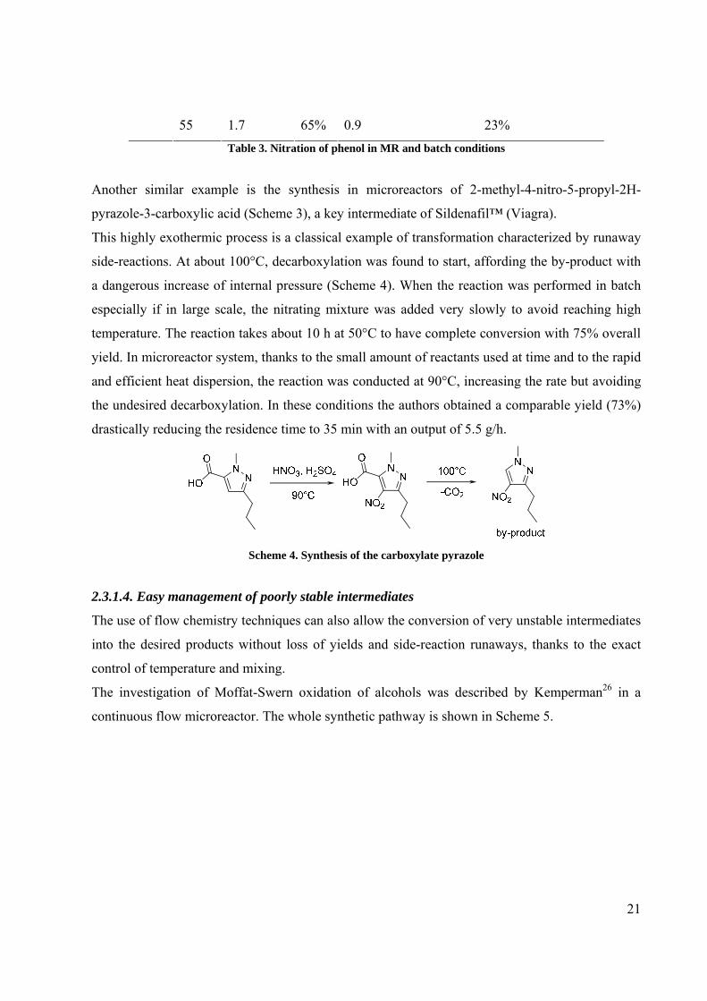
Another similar example is the synthesis in microreactors of 2-methyl-4-nitro-5-propyl-2H-
pyrazole-3-carboxylic acid (Scheme 3), a key intermediate of Sildenafil™ (Viagra).
This highly exothermic process is a classical example of transformation characterized by runaway
side-reactions. At about 100°C, decarboxylation was found to start, affording the by-product with
a dangerous increase of internal pressure (Scheme 4). When the reaction was performed in batch
especially if in large scale, the nitrating mixture was added very slowly to avoid reaching high
temperature. The reaction takes about 10 h at 50°C to have complete conversion with 75% overall
yield. In microreactor system, thanks to the small amount of reactants used at time and to the rapid
and efficient heat dispersion, the reaction was conducted at 90°C, increasing the rate but avoiding
the undesired decarboxylation. In these conditions the authors obtained a comparable yield (73%)
drastically reducing the residence time to 35 min with an output of 5.5 g/h.
Scheme 4. Synthesis of the carboxylate pyrazole
2.3.1.4. Easy management of poorly stable intermediates
The use of flow chemistry techniques can also allow the conversion of very unstable intermediates
into the desired products without loss of yields and side-reaction runaways, thanks to the exact
control of temperature and mixing.
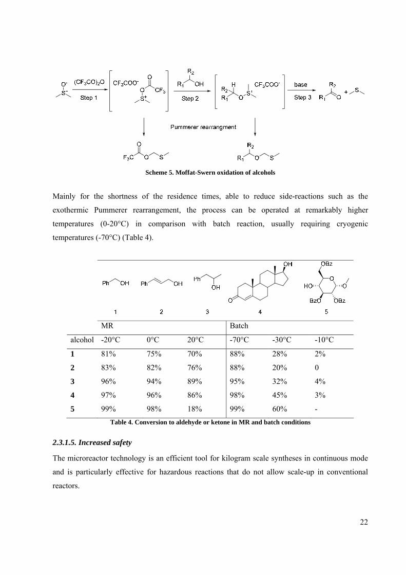
The investigation of Moffat-Swern oxidation of alcohols was described by Kemperman26 in a
continuous flow microreactor. The whole synthetic pathway is shown in Scheme 5.
22
Scheme 5. Moffat-Swern oxidation of alcohols
Mainly for the shortness of the residence times, able to reduce side-reactions such as the
exothermic Pummerer rearrangement, the process can be operated at remarkably higher
temperatures (0-20°C) in comparison with batch reaction, usually requiring cryogenic
temperatures (-70°C) (Table 4).
MR Batch
alcohol -20°C 0°C 20°C -70°C -30°C -10°C
1 81% 75% 70% 88% 28% 2%
2 83% 82% 76% 88% 20% 0
3 96% 94% 89% 95% 32% 4%
4 97% 96% 86% 98% 45% 3%
5 99% 98% 18% 99% 60% - Table 4. Conversion to aldehyde or ketone in MR and batch conditions
2.3.1.5. Increased safety
The microreactor technology is an efficient tool for kilogram scale syntheses in continuous mode
and is particularly effective for hazardous reactions that do not allow scale-up in conventional
reactors.

23
In fact in process research, there are many reactions involving explosive or toxic reagents such
diazo compounds, azides, etc. Often time and resources have to be devoted to find suitable
experimental and engineering designs to safely scale-up these reactions or to design safer
alternative syntheses. Since the actual reaction volumes in a microreactor are very small, the safety
concerns are minimized (Figure 11).
Batch Microeactor
Figure 11. Dependence of the safety by the reaction volume
This has been proven in this example in which a ring-expansion reaction was studied into a
microreactor system (Scheme 6).27
Scheme 6. Ring-expansion reaction
In batch the reaction occurred with a good yield (90%) at -25°C but it was limited to small scale
because it is highly exothermic. In fact, after the addition of the diazo reagent the temperature
raised at 45°C and the evolution of N2 caused overpressure in the reactor. Because of these
reasons, scaling up this reaction to kilogram scales safely in a conventional reactor is not
recommended. When the reaction was performed under flow conditions, the ring expansion
occurred with 89% yield, with a residence time of 1.8 min and with an output of 91 g/h.
2.3.2. Advantages related to the continuous nature of the process
To the continuous nature of the flow chemistry technique are associated some benefits that will be
described below and in the next paragraph:
• Easy scale-up

24
• Possible use solid supported reagents or scavenger in-line
• Continuous sequential steps
• Reaction conditions independently varied during the experiment facilitating the
optimisation process
2.3.2.1. Easy scale-up
Continuous process offers a quick and easy scale-up procedure. The synthetic conditions set up for
few milligrams are easily used for grams or even kilograms by simply using the flow reactor for
an extended time or by employing multichannel parallel reactors (numbering-up process), without
variations in yields, purities and safety (Figure 12).
Figure 12. Scale-up in flow chemistry
On the contrary, traditional batch scale-up often requires modifications of laboratory synthetic
protocols, optimization of reactor parameters, such as mixing and heat control.
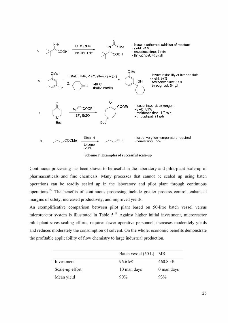
Unsafe synthetic steps and reaction necessitating accurate temperature control are typical scaled-
up processes improved by microreactor approach. Some interesting synthetic examples of
successful scaling-up are summarized in Scheme 7.28
25
Scheme 7. Examples of successful scale-up
Continuous processing has been shown to be useful in the laboratory and pilot-plant scale-up of
pharmaceuticals and fine chemicals. Many processes that cannot be scaled up using batch
operations can be readily scaled up in the laboratory and pilot plant through continuous
operations.29 The benefits of continuous processing include greater process control, enhanced
margins of safety, increased productivity, and improved yields.
An exemplificative comparison between pilot plant based on 50-litre batch vessel versus
microreactor system is illustrated in Table 5.19 Against higher initial investment, microreactor
pilot plant saves scaling efforts, requires fewer operative personnel, increases moderately yields
and reduces moderately the consumption of solvent. On the whole, economic benefits demonstrate
the profitable applicability of flow chemistry to large industrial production.
Batch vessel (50 L) MR
Investment 96.6 k€ 460.8 k€
Scale-up effort 10 man days 0 man days
Mean yield 90% 93%

26
Specific solvent consumption 10 l/kg 8.3 l/kg
Required personnel per facility 2 man 1 man
Production rate 427 kg/a 536 kg/a
Specific production cost 7227 €/a 2917 €/a Table 5. Comparison between pilot plant versus microreactor system
2.3.2.2. Continuous sequential steps
Another possibility that flow chemistry could offer to organic synthesis is performing sequence of
two or more reactions using flow reactors, without breaking the sequence with workup and
purification. The sequence of reactions can occur directly through a series of connected reactors,
which parameters are accurately set for the specific synthetic step. Flow technique permits the
linking of individual reactions into multi-step sequences, allowing for one reaction to flow
seamlessly into another and creating a rapid route to the desired more complex product by
combining multiple synthetic steps into a continuous operation. Between each step may be
present, when necessary, a system for trapping and eliminating possible by-products, without
interrupting the flow.
Different examples of multi-step synthesis performed under flow conditions are discussed below.
The first example is the three-step continuous synthesis of a collection of oxadiazole derivatives
(Scheme 8).30 In batch mode the sequence requires long reaction times, mainly for the final
cyclization step. The authors, thanks to application of superheating conditions and an accurate
mixing of reactants, performed the entire process sequentially through the joint of three
microreactors, shortening the reaction time to about 30 min and obtaining a sufficient amount of
product for a full characterization and library supply.
Scheme 8. 1,2,4-Oxadiazole synthesis
In the next recent example of Baxendale and co-workers the synthetic power of performing
multistep reaction sequences under flow conditions is impressively demonstrated.31 The
palladium-catalysed acylation of terminal alkynes for the synthesis of yne-ones and their further
transformation into various heterocycles is described. Particularly advantageous is the purification

27
of the final product performed in-line using a suite of packed glass tubes containing appropriate
scavenger materials (Scheme 9).
Scheme 9. Two-step formation of pyrazoles from yne-ones
Another example of the combination of multi-step synthesis and solid-supported scavengers and
reactants in a flow system was reported by Ley for the preparation of the alkaloid natural product
(±)-oxomaritidine (Scheme 10).32 The whole seven-step synthesis was carried out through a
microfluidic pumping system that pushed the solution of reactants into a series of pre-packed
columns containing immobilized reagents, scavengers and catalysts. The expected product was
obtained in less than a day with 40% yield and 90% purity, through the simple evaporation of the
solvent without any isolation and purification of the intermediates. The synthesis of this product
and other interesting examples of multi-steps pathway will be describe with more details in
Chapter 3 and 4 of this thesis.
Scheme 10. Synthesis of (±)-Oxomaritidine

28
The possibility of using separator devices in continuous processes without interrupting the
pumped flow opens the way to multi-step syntheses that require intermediate workup stages. An
interesting application of this principle and tools was reported by Jensen.33 This three-step
synthesis of carbamate derivatives was performed by Curtius rearrangement starting from
commercially available acyl chlorides (Scheme 11). Each step was carried out in a microreactor. A
microfluidic separation system was integrated after the first and the second reactor, allowing the
ease removal of inorganic salts through liquid/liquid extraction (Step 1) and of produced gas
through gas/liquid separator (Step 2). Isocyanate intermediate was then pumped into three
microreactors with three different alcohols affording simultaneously three carbamate products.
The work demonstrated the simultaneous use of reactors and separator devices in flow mode,
allowing the in situ generation and consumption of hazardous intermediates such as azides and
isocyanates.
Scheme 11. Synthesis of carbamate derivatives by Curtius rearrangement
2.3.3. Multi-phase systems
2.3.3.1. Solid-liquid reactions
The structure of the flow devices, based on the small dimension of channels that improves mixing
efficiency, fitted thoroughly to an extensive use in heterogeneous conditions. Solid-liquid,
immiscible liquid-liquid, liquid-gas and solid-liquid-gas phase conditions are applications widely
studied and exemplified through the flow chemistry.
The use of supported, anchored and encapsulated reagents, scavengers and catalysts perfectly suits
with flow conditions, due to the intimate contact between the reactants present in solution and the
pad of the stationary reactive phase. In this small space the reaction occurs and then the product is
flowed away. In every time the relative amount of bound reactant is large, especially in the case of
supported catalysts.
The main limitation is the total amount of supported reagents and scavengers that the system can
tolerate, relating on its scale-up threshold. One example of two-phase solid-liquid system, reported

29
by Watts,34 illustrates the protection of aldehydes and ketones with dithiol species. In batch-mode,
Lewis or Brønsted acid catalyst and, usually, an excess of thiolating agent are necessary to
promote the reaction, making the purification step essential. Also the use of supported catalyst
does not avoid the need for excess of reactant because of the mechanical degradation of the
support, which leads to reduced reagent lifetimes. In a flow system with Amberlyst-15 as acidic
supported catalyst, the protection reaction may be performed in very short times (few minutes
compared to at least one day in batch mode) using a stoichiometric amount of dithiol (Scheme 12).
Scheme 12. Protection of aldehydes and ketones with dithiol species
The subsequent simple evaporation of solvent affords the expected thioacetals and thioketals in
very high yields (> 99%) and purities.
Another impressive example is reported by Ley and co-workers in the synthesis of 1,4-
disubstituted 1,2,3-triazoles in a modular flow reactor (Scheme 13).35
Scheme 13. Synthesis of 1,4-disubstituted 1,2,3-triazoles
The scavengers and the benefits associated to this protocol are described below:
• CuI immobilized on Amberlyst (PS-NMe2: high loading and retention of basic
functionality)
• PS-Thiourea used as metal-scavenging resin.
• PS-PPh2 captured the azide excess onto the solid phase as an iminophosphorane.
• No handling work-up required.
• Exclusion of the oxygen from the system preventing Glaser homocoupling.
• Reduces exposure to potentially explosive and highly toxic chemicals.
• Yields 70-93%; purity after solvent evaporation >95%

30
Another recent application of this type of solid/liquid reaction approach is the use of nanoparticles
as supports for catalyst which are rapidly gaining attention due to their promise to show activities
as found for homogeneous catalysts but being readily recoverable due to their heterogeneous
nature.36 Among them, magnetic nanoparticles as supports for catalysts are especially attractive for
flow processes, since the catalyst can be confined and at the same time agitated in a reactor by a
rotating magnetic field, thus avoiding potential problems of clogging membranes or filters that are
commonly employed as barriers for immobilized catalysts. This principle was successfully
demonstrated in the asymmetric benzoylation of 1,2-diols using copper(II)-azabis(oxazoline)
catalysts that had been covalently attached to carbon coated cobalt nanoparticles (Figure 13).37 In
five consecutive runs with a flow rate of 0.2 ml/min excellent yields and enantioselectivities had
been achieved for the title reaction with minimal leaching (<1%) of the nanoparticle supported
catalyst.
Figure 13.Kinetic resolution of (±)-1,2-diphenylethane-1,2-diol catalyzed by a Cu(II)-azabis(oxazoline) complex
immobilized on magnetic nanoparticles
2.3.3.2. Liquid-liquid reactions
Biphasic system obtained by two immiscible liquids is another kind of multi-phase reactions that
can be improved by flow apparatus. In the small channels of the flow system, thanks to a T-shaped
geometry of the inlet junction, a segmented flow of the two liquids is formed (Figure 14).
Inside each segment, because of the interaction of the liquid with the channel wall, a fluid vortex
is generated, causing rapid mixing and a continuous refreshing of the interface. The contact
surface between the immiscible liquids is increased, promoting the reactions that occur at the
interface.

31
Org
Aq
Org
Aq
Figure 14. Segmented flow
One example of this use of the flow reactor was reported for the simple biphasic hydrolysis of 4-
nitrophenyl acetate, dissolved in toluene, with an aqueous solution of NaOH.38 Comparison of the
results obtained in batch and in a microreactor is summarized in Table 6.
Reaction time (min) Yield Note
Batch 10 53%
Batch 2 8%
MR 2 51%
MR 2 67% 0.1 eq Bu4NHSO4
MR 2 82% sonication
MR 2 88% 0.1 eq Bu4NHSO4 and sonication Table 6. Biphasic hydrolysis of 4-Nitrophenylacetate
Segmented flow was able to afford the same yield (50%) as batch but in shorter time. Moreover,
with the same residence time, the yield was further increased by the combination of segmented
flow, phase-transfer catalysis (Bu4NHSO4) and sonication.
The immersion of the reactor in an ultrasonic bath led to the formation of irregular sized segments
that increased the interfacial area thus improving the reaction rate (Figure 15).

32
Org
AqUltrasound Bath
Org
Aq
Org
AqUltrasound Bath
Org
Aq
Org
AqUltrasound Bath
Org
AqUltrasound Bath
Org
Aq
Figure 15. Segmented flow and flow under sonication
Liquid/liquid biphasic segmented flow, which is an excellent solution for the phase-transfer
reactions, was used for setting-up Wittig reactions39 and alkylations of phenols.
Aromatic and heteroaromatic aldehydes were combined with (ethoxycarbonylmethyl) triphenyl
phosphonium bromide, in presence of bases, affording the desired substituted cinnamic esters in
high yields (Scheme 13). Compared to the classical batch phase-transfer conditions, the reactions
required shorter reaction times and were performed without any phase-transfer catalyst. The
beneficial effect of the catalyst was replaced by the immersion of the reactor into an ultrasonic
bath with consequent increase of the interfacial area between the immiscible solvents. In these
conditions, few minutes residence times are enough to reach the complete conversion.
Scheme 14. Wittig reaction
The alkylation of aromatic phenols with benzyl bromide and iodomethane is another successful
combination between phase-transfer catalysis and flow systems (Scheme 15). With a catalytic
amount of tetrabutylammonium bromide and using sodium hydroxide as base, complete
conversions and high yields were obtained just in few minutes, compared to hours required when
traditional batch conditions were applied.
OH OR'R'X, NaOH, TBAB
CH2Cl2, H2O90°C
R Ryields up to 95%
Scheme 15. Phenol alkylation

33
2.3.3.3. Gas-liquid reactions
Flow chemistry has also showed its potentiality in gas-liquid biphasic reactions. By an accurate
regulation of gas pressure and liquid flow, an annular flow regime could be obtained: the liquid is
forced to form a thin film against the surface walls, while the gas flows through the centre,
generating a very high interfacial area.
The high contact surface, the punctual control of temperature and the small scale typical of the
flow reactors allow a safer use of toxic and dangerous gases, such as carbon monoxide, hydrogen,
fluorine and chlorine, which often require a sophisticated apparatuses in batch mode.
Carbon monoxide, for example, was used for the first time in a flow device for the formation of
amides through carbonylative coupling (Scheme 16). The liquid solution, consisting of a mixture
of arylhalide, palladium-phosphine catalyst and benzylamine, was flow into the microreactor
while the gas pressure produced an annular flow pattern. With very short residence times (less
than 2 min) the obtained yields were comparable and often better than in the classical batch
reaction.40
Scheme 16. Formation of amides through carbonylative coupling
Elemental fluorine gas was employed in flow devices for the formation of carbon-fluorine bond.
The process is highly exothermic, but thanks to the effective dissipation of the heat and the
efficient gas-liquid mixing of flow reactors, direct fluorination may be performed in good yields
and high selectivity. Chambers,41 for example, reported selective mono-fluorination of dicarbonyl
compounds and aromatic rings (Scheme 17).
Scheme 17. Selective mono-fluorinations of dicarbonyl compounds and aromatic rings

34
Fluorine gas was introduced into the system as a 10% mixture with nitrogen, while the reactant
was dissolved in formic acid. The process was set up for laboratory scale, but, by simple
increasing the number of the channels, the system may be appropriate for synthesis on large scale.
2.3.3.4. Gas-liquid-solid reactions
Further step of multi-phase flow reactions is the combination of solid, liquid and gas phases. An
example of instrument dedicated to hydrogenation reactions that reaches this goal is H-CubeTM
(ThalesNano) in which a solution of substrate is mixed with gaseous hydrogen, through a pre-
packed cartridge containing the heterogeneous catalyst. In the short cartridge path, also thanks to
the wide range of pressure and temperature (up to 100 bar and 100°C), the reduction of the
substrate is quickly performed and then the product is flowed away and collected.
The instrument is equipped with an electrolytic cell that produces hydrogen directly from water. In
this way, gas cylinders or other sources of hydrogen are not necessary, making the system safer
than classical batch apparatus. In addition, no catalyst filtration or direct catalyst handling are
further advantageous points in term of safety. Many benefits are associated to this tool and are
briefly summarized below:
• More efficient and safer process (reduced exposure to the catalyst and the risks involved
with pyrophoric catalyst, no filtration required at the end of the experiment).
• The catalyst can be reused for different substrates.
• High catalyst to substrate-hydrogen ratio at each time.
• Good mixing of the three phases.
• Continuous flow process and short residence time allow rapidly reaction optimization on
novel substrates.
• T, P and flow may be modified ‘on fly’.
• Catalyst cartridges may be quickly exchanged to determine the effect of different catalyst.
Some published papers report the use of H-CubeTM as good and reliable replacement of traditional
hydrogenation methods.42
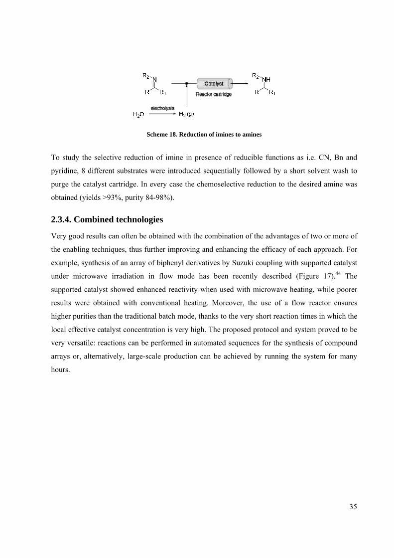
An example is the catalytic reduction of imines to amines described by Ladlow and co-workers.43
The reduction of imines was assessed using a 10% Pd/C cartridge under 20 bar H2 pressure
(Scheme 18).
35
Scheme 18. Reduction of imines to amines
To study the selective reduction of imine in presence of reducible functions as i.e. CN, Bn and
pyridine, 8 different substrates were introduced sequentially followed by a short solvent wash to
purge the catalyst cartridge. In every case the chemoselective reduction to the desired amine was
obtained (yields >93%, purity 84-98%).
2.3.4. Combined technologies
Very good results can often be obtained with the combination of the advantages of two or more of
the enabling techniques, thus further improving and enhancing the efficacy of each approach. For
example, synthesis of an array of biphenyl derivatives by Suzuki coupling with supported catalyst
under microwave irradiation in flow mode has been recently described (Figure 17).44 The
supported catalyst showed enhanced reactivity when used with microwave heating, while poorer
results were obtained with conventional heating. Moreover, the use of a flow reactor ensures
higher purities than the traditional batch mode, thanks to the very short reaction times in which the
local effective catalyst concentration is very high. The proposed protocol and system proved to be
very versatile: reactions can be performed in automated sequences for the synthesis of compound
arrays or, alternatively, large-scale production can be achieved by running the system for many
hours.

36
Figure 17. Example of combined technology: PASPS, MAOS and flow chemistry
2.3.5. Conclusion
In the light of all these examples, we can assess that flow chemistry system is not only a mere
laboratory or academic new fashion.
The advantages and the drawbacks associated to this technique are summarized and below:
Advantages:
1) Small dimension of the channels
• Precise control of reaction conditions
• Efficient mass and heat transfer
• Superheating
• Safer and more selective processes
• Toxic and explosive intermediates are prepared in situ and directly reacted
• Easy management of poorly stable intermediates
• Decreased inputs and waste
2) Continuous nature of the process
• Possible use solid supported reagents or scavengers in-line
• The reaction conditions can be independently varied during the experiment facilitating the
reaction optimisation process

37
• Easy scale-up
• Continuous sequential steps
Drawbacks:
• Mainly useful for relatively fast reaction
• Incompatible with solid reagents
• Very sensitive to precipitating product

38
Chapter 3. Flow chemistry in Medicinal Chemistry:
state of the art

39
3.1. Introduction
Modern drug discovery tends to be an iterative process which usually begins with a target
orientated design phase and then proceeds to the synthesis of a small focused compound collection
followed by biological evaluation.45 The results and observations of these initial assays generate
primary information concerning potency, selectivity, pharmacokinetic properties and other
parameters which are reincorporated into the design loop to further continue the optimisation
process (Figure 18).
Figure 18. The iterative cyclic drug design
As a result improving any step of the sequence immediately reduces the overall development time
in this closed loop approach to drug discovery.46 While many high-throughput screening methods,
computational modeling techniques and predictive software packages exist and have greatly aided
medicinal discovery, the synthesis component can still sometimes constitute a significant
bottleneck. Consequently, new thinking and alternative approaches for molecular assembly are
required.
Of these new enabling technologies continuous processing using chemical microreactors
represents an attractive potential solution for medicinal chemists because of the rapid early-stage
reaction optimization and scale-up.47
In literature a large number of different types of reaction have been already studied showing how
flow chemistry can be successfully applied to the organic synthesis (Figure 19).

40
Figure 19. State of the art of single-step continuous-flow reactions.
However the potentiality of this technique is not yet broadly exploited in Medicinal Chemistry;48
just in recent years flow processes started to be applied in this field.49
3.1.1. Application of flow chemistry towards the synthesis of drugs
Flow processes are rapidly finding applications towards the synthesis of biologically active
compounds and drugs, taking advantage of shorter reaction times, higher yields, and facile scale-
up of a single target compound, but also of more efficient generation of compound libraries by
introducing families of building blocks sequentially during a given reaction sequence.
Rimonabant and Efaproxiral (Figure 20), two pharmaceutically active substances, were prepared
through a safe, functional-group-tolerant and high-throughput version of the trimethylaluminium
mediated amide bond formation developed by Seeberger in a microreactor system.50
Figure 20. Rimonabant (a) and Efaproxiral (b)
Carbon-Carbon Bond-Forming Aldol condensation Claisen Rearr Suzuki coupling Cyclopropanation Michael addition of nitromethane Oxidations and Reductions Moffat-Swern Heterocycle Formations Carbon-Nitrogen Bond-Forming Carbamates Amines Peptides Curtius Amide by AlMe3 Carbon-Oxygen Bond-Forming Ring opening of terminal epoxides Sulfur-Nitrogen Bond-Forming
Fluorinations Reactions with Diazo Reagents Radical Hydrosilylation Polymerizations Photochemical Precipitate-Forming Aromatic Electrophile Substitution Aminocarbonylation Reactions Using Organocatalysts Enzymatic Cyanohydrins

41
The use of a continuous flow microreactor for β-amino alcohol formation by epoxide aminolysis
was developed in the work of Jamison.51 In particular the aminolysis of epoxides under flow
conditions was applied to the synthesis of Metoprolol and Indacaterol™ (selective β1-
adrenoreceptor blocking agents). The later compound was produced in a microreactor at a
residence time that was 1/60th of that reported in the literature with similar yield (Figure 21).
HNO
HO
NHHO
OOH
NH
O
(c) (d) Figure 21. Metoprolol (c) and of Indacaterol™ (d)
Diazoketone is a versatile pharmaceutical intermediate of N-Boc-(1R,2S)-benzylhydroxy-3-
chloropropylamine, a precursor to pharmaceutically active ingredients that act as a human
immunodeficiency virus (HIV) protease inhibitors (Figure 22).
ON2
Ph
BocHN Cl
Ph
BocHNOH
(e) (f) Figure 22. Diazoketone (e) and N-Boc-(1R,2S)-benzylhydroxy-3-chloropropylamine (f)
A continuous flow system, giving the compound in higher yields at more readily attainable
temperatures than the analogous batch process was successfully design, build, and implemented.
Specifically, quantitative in situ yields were obtained for the transformation of N-Boc-(S)-
phenylalanine to the correspondent mixed anhydride and its subsequent reaction with hazardous
trimethylsilyldiazomethane to the 1-benzyl-3-diazo-2-oxopropylcarbamic acid tert-butyl ester
(e).52 The continuous flow process that was designed takes advantage of the superior heat transfer
capabilities of packed tubular flow reactors and their inherent increased safety. It allowed to
efficiently and safely carrying out a two step synthetic sequence that involves temperature
sensitive intermediates and hazardous chemical reactant.

42
The first continuous flow synthesis of imidazo[1,2-a]pyridine-2-carboxylic acids directly from 2-
aminopyridines and bromopyruvic acid was developed, representing a significant advance over the
corresponding in-flask method.53 The process was applied to the multistep synthesis of a Mur
ligase inhibitor with potential antibacterial activity, using a two microreactor, multistep continuous
flow process without isolation of intermediates (Scheme 19). The in-flask synthesis of this
compound was reported to proceed in 16.4% overall yield over two steps. Using the continuous
flow method, the Mur ligase inhibitor was prepared in a single process with 46% yield.
Scheme 19. Continuous flow preparation of Mur ligase inhibitor
Recently a concise, flow-based synthesis of Imatinib (Gleevec; Figure 23), a compound used for
the treatment of chronic myeloid leukemia, was described.54
Figure 23. Imatinib and planned disconnections for its flow synthesis
All the steps are conducted in tubular flow coils or cartridges packed with reagents or scavengers
to effect clean product formation (Scheme 20). An in-line solvent switching procedure was
developed enabling the procedure to be performed with limited manual handling of the
intermediates.

43
Scheme 20. Flow synthesis of Imatinib
This represents a significant improvement over the existing protocols that require manual
intervention. The synthetic route has also the potential to be used for the synthesis of analogue
compounds and clearly demonstrates the role of flow chemistry techniques in the assembly of
challenging molecules.
3.1.2. Flow chemistry applied to the synthesis of Med-Chem libraries
Flow chemistry may be also applied to the preparation of collections of compounds, using the
basic concepts of the parallel/combinatorial chemistry.
In fact multistep continuous-flow systems appear to be particularly suitable for this branch of the
medicinal chemistry, where a large number of analogues can be synthesized by the same reaction
sequence consisting of a few relatively simple steps, like amide couplings, reductive amination,
catalytic hydrogenations, and metal-catalyzed coupling reactions. In particular this approach can
be very helpful during the Hit Validation and Lead Identification phases.
The most logical and simple strategy for the preparation of a library of derivatives is the parallel
approach, where the number of reaction channels is the same as the number of final products and

44
starting materials are distributed to all the reaction channels in different combinations.55 The main
limitation of this synthetic strategy is the high number of reactors and the complicated piping
system that are necessary for the combination of a large number of starting materials.
An alternative and more favorable approach is the sequential plug flow synthesis. In this case the
solutions of reactants are introduced in sequential way into the same reactor. The system offers
high flexibility because the reaction conditions (temperature, reaction time, scale, reagent ratio)
can be controlled independently and individually for each reaction sequence. All starting materials
enter into the system in pulse sequence and their elution profile from the reactor is analyzed by
measuring UV absorption, allowing the correct and independent collection of the products. In any
case each reaction plug is separated from another plug by a spacer solvent that serves also as
washing step, avoiding cross-contaminations.
One of the first examples of this type, even if it was not part of a discovery program, was a fully
automated flow-through process for the production of secondary sulfonamides presented by
Ladlow and co-workers.56 Primary sulfonamides were monoalkylated using a two-step “catch and
release” protocol to generate library products of high purity. The automated flow synthesis
platform incorporates four independent reactor columns and is able to perform automated column
regeneration. A 48-member sulfonamide library was prepared as two 24-member sub-libraries,
affording library compounds in good yields and high purities without the need for further column
chromatographic (Scheme 21).
Scheme 21. Automated flow-through synthesizer configuration for sulfonamide library preparation
A general protocol for the preparation of inhibitors of casein kinase I using flow-assisted chemical
processing techniques was developed and a small collection of imidazopyridazine (Scheme 22)
was synthesized using a four step reaction sequence.

45
Scheme 22. General route to the imidazo[1,2]pyridazine core
The multi-step synthesis involved a safely scaling up reaction utilizing organometallic bases at
low temperature, a monobromination facilitated by application of a solid supported reagent, a
cyclocondensation reaction to generate the imidazopyridazine core (Scheme 23). Finally an
autosampler was used to perform automated SNAr reactions to give a collection of diversified
imidazopyridazine derivatives.
Scheme 23. Flow synthesis of the imidazopyridazine cores
The application of the above strategy was also described by Schwalbe57 for the sequential
synthesis of a library of Ciprofloxacin analogues. The five-step synthetic pathway is reported in
Scheme 24. Step 2 (addition/elimination) and Step 4 (aromatic nucleophilic substitution) are the
points used by the authors to introduce diversity in the compound collection. The amount of each
member of the library was at least 100 mg and purity was satisfactory for drug discovery process.
The yields were in 59-99% range and the potential cross-contamination was assessed and
excluded, demonstrating the reliability of the sequential synthetic method.

46
Scheme 24. Sequential synthesis of a library of Ciprofloxacin analogues
An interesting work in this field is the preparation of a library of 1,4-disubstituted 1,2,3-triazoles
synthesized using a copper flow reactor.58 Organic azides, generated in situ from alkyl halides and
sodium azide, were reacted with acetylenes using the copper-catalyzed Huisgen 1,3-dipolar
cycloaddition (Scheme 25). This process eliminates both the handling of organic azides and the
need for additional copper catalyst and permits the facile preparation of numerous triazoles in a
continuous flow process. Importantly, reaction segments were separated by an immiscible fluorous
spacer, perfluoromethyldecalin, that prevented segment diffusion and reaction trailing. Using this
approach, multiple segments could flow through the reactor at any one time, maximizing the
system’s efficiency and permitting rapid library development (medicinal chemistry) or reaction
optimization (process research).
Scheme 25.One-pot click reaction using 4-ethynyltoluene and 2-bromoethanol
In the last example the construction of a continuous-flow sequence designed for rapid synthesis of
new ligands in medicinal chemistry by combination of three building blocks was described.59 The
potentiality of the technique was demonstrated by the synthesis of a library of diverse drug-like
test compounds. Targeting the chemokine receptor CCR8, which is of interest for treatment of
various inflammatory and allergic conditions, a system for on-demand production of compounds
with pharmacophores corresponding to known CCR8 ligands was constructed. The sequence
consisted of three reaction sequence (two scavengers in between), where a mono Cbz-protected
diamine is reacted with an isocyanate, deprotected (H-cube), and reacted further with an alkylating
agent (Scheme 26).

47
Scheme 26. Three-step continuous-flow for synthesis of receptor ligands
Once the three-step flow sequence was assembled and optimized, it proved to be a powerful and
robust tool for rapid production of diverse compounds. Sequential production with a minimum of
effort compared to batch or parallel synthesis contributes to minimizing the turnaround time of the
critical design-synthesis-screening cycle.
In the next two chapters our works toward the application of flow chemistry to Medicinal
Chemistry field will be described. An important aim of these projects was to demonstrate that flow
synthesis can be a very effective and flexible tool for rapid synthesis of compounds and that the
advantages associated to this technique can be useful in the drug discovery and optimization
process.

48
Chapter 4. Efficient continuous flow synthesis of
hydroxamic acids and SAHA

49
4.1. Flow synthesis of a collection of hydroxamic acids60
In the framework of my PhD thesis exploring the application of the so called “Enabling
Techniques” in a medicinal chemistry laboratory, my efforts were devoted to the evaluation of the
benefits that continuous flow chemistry could provide in Drug Discovery programs and in the
synthesis of natural products in comparison with traditional synthetic techniques.
Here we report a general and efficient procedure for the conversion of esters into the
corresponding hydroxamic acids with good yields and purities using a commercially available
continuous flow reactor. Hydroxamic acids occur in several molecules with a wide spectrum of
biological activities61 such as antibacterial, antifungal, antiinflammatory, antiasthmatic, and
anticancer properties. In particular this moiety is present in potent matrix metalloproteinase62 and
hystone deacetylase63 inhibitors because hydroxamic acids are strong bidentate metal-ion-
chelating agents that interact with zinc(II)-containing proteins. Given the importance of this
functionality, the development of new methodologies for a general and efficient synthesis are still
of great interest, although several methods have been developed and published so far.64 As a part
of a medicinal chemistry project, a simple conversion of ester into hydroxamic acid was envisaged
as a suitable and convenient synthetic method for the preparation of a collection of compounds
featuring this particular moiety (Figure 24).
Figure 24. Flow synthesis of hydroxamic acids
Firstly the use of methylbenzoate (1a) to optimize the parameters (flow rate, residence time, and
temperature) was investigated. A mixture of 1a (0.5 M in MeOH) and hydroxylamine (1:10 ratio)
was simultaneously pumped into the flow reactor with a solution of MeONa (0.5 M in MeOH) of
MeONa, allowing efficient mixing in the PTFE tubing at the selected temperature (Scheme 27).
The optimization of the experimental parameters was systematically investigated by varying flow
rate, temperature, and reactor volume. The reaction set-up was greatly facilitated by continuous
flow conditions and a significant number of runs were rapidly conducted in a sequential manner
(Table 7).

50
Entry Flow Rate (ml/min)
Residence time (min)
T (°C)
Conversion (%)a
1 1 5 50 52
2 1 5 70 65
3 1 5 80 58b
4 0.5 20 60 76
5 0.5 20 70 74
6 0.5 30 70 80 a Conversion was determined by LC/MS at 215 nM b Presence of the corresponding carboxylic acid as by-product
Scheme 27.; Table 7. Synthesis of hydroxamic acid and pptimization of experimental parameters
The temperature of 70°C resulted in the best compromise to have good conversion without the
formation of the corresponding carboxylic acid. This by-product was significantly present when
the reaction was performed at 80°C. The conversion into the hydroxamic acid was improved by
prolonging the residence time by lowering the flow rate and increasing the volume of the reactor.
When the reaction was performed at 70°C for 30 min, 80% conversion was achieved by LC/MS,
resulting in 82% yield of isolated 2a (entry 6). For comparative purposes the reaction was run both
as a standard batch process and in a sealed tube under microwave irradiation, applying the same
conditions of temperature, concentration of reagents, and reaction time as optimized in the flow
protocol (Table 8).
Entry Experimental Condition Conversion (%)a 1 Batch reaction 58
2 Sealed tube with MW irradiation 72
3 Flow system 80 a Conversion was determined by LC/MS at 215 nM
Table 8. Comparison of reaction performed under different experimental condition
We found that such conditions gave moderate conversion using conventional equipment (58%,
entry 1) and comparable result under microwave irradiation (72%, entry 2). The precise control of
temperature distribution and the efficient heating and mixing associated with flow technique
minimized the formation of the corresponding carboxylic acid as a by-product and ensured that
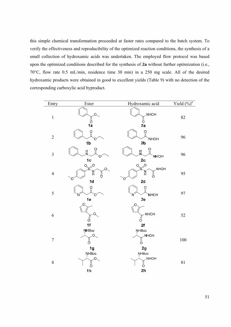
51
this simple chemical transformation proceeded at faster rates compared to the batch system. To
verify the effectiveness and reproducibility of the optimized reaction conditions, the synthesis of a
small collection of hydroxamic acids was undertaken. The employed flow protocol was based
upon the optimized conditions described for the synthesis of 2a without further optimization (i.e.,
70°C, flow rate 0.5 mL/min, residence time 30 min) in a 250 mg scale. All of the desired
hydroxamic products were obtained in good to excellent yields (Table 9) with no detection of the
corresponding carboxylic acid byproduct.
Entry Ester Hydroxamic acid Yield (%)a
1
82
2
96
3
96
4
95
5
97
6
52
7
100
8
2h
NHOH
O
NHBoc
81

52
Entry Ester Hydroxamic acid Yield (%)a
9
83
a Isolated yields; purity > 95% (LC/MS) Table 9. Conversion of esters into hydroxamic acids under flow conditions
The data reported in Table 9 clearly show that the formation of hydroxamic acids from esters is
quite general and occurs smoothly in the continuous flow system. In fact simple aryl or alkylaryl
esters (entries 1 and 2), simple amino esters (entry 3) and Boc-protected amino esters (entries 7-9),
sulfonamido-ester (entry 4), and heteroaryl esters (entries 5 and 6) were suitable substrates for the
reaction. Moreover the optimized reaction conditions were successfully applied to
enantiomerically pure esters without loss of stereochemical integrity. The specific optical rotation
for the hydroxamic acid of N-Boc-alanine methyl ester 2g was found to be identical to that
reported in literature for the enantiopure compound {[α]20D -28; Lit [α]20
D -29 (c 1, MeOH)}.62a
With compounds 1b, 1d, and 1j the obtained results show an improvement if compared to the
microwave-assisted process described in the literature.62a Noticeably for compound 1d the isolated
yield was increased from 33% to 95%; in the other cases an average improvement of about 20%
was observed. Simple scale-up makes the continuous flow technique very advantageous when
compared to MW systems, as up to now MW heating has proved to be unsuitable for large scale
processes. Moreover the risks associated with failing to scaleup a process are limited using
continuous flow. The reaction condition setup on the microreactor can be directly transferred to
production on larger scale without the need for reoptimization by simply using the flow reactor for
an extended time or by employing multichannel parallel reactors (numbering-up process).65
A demonstration of this preparative capability was readily obtained. Applying the optimized
conditions and doubling the concentration of the starting materials, 4.3 g of N-hydroxy-2-
phenylacetamide 2b was straightforwardly produced after 1.5 h (output 2.9 g/h). Yield and purity
were similar to that of the smaller scale, proving that the reaction conditions identified for the
production of a few milligrams can be transferred to a larger scale without any further
optimization. In addition to the easy scalability of the protocol, the careful control of temperature
exotherms and the small volumes employed by flow reactor allow the safer use of the highly toxic
and potentially explosive hydroxylamine.66

53
4.2. Flow synthesis of SAHA60
On the basis of the good results obtained in the development of the continuous flow synthesis of
hydroxamic acids, this new methodology was applied to the synthesis of suberoylanilide
hydroxamic acid (SAHA, Scheme 27).
This compound, one of the early histone deacetylase (HDAC) inhibitors discovered by Breslow
and colleagues,67 was approved by the U.S. FDA in October, 2006 for the treatment of patients
with cutaneous T-cell lymphoma (CTCL).68 Despite the several synthetic procedures for the
preparation of SAHA that have been reported,69 as far as we know, none of them described the
synthesis under flow conditions. Our two-step sequence entails the conversion of the
commercially available methyl suberoyl chloride 3 into methyl suberanilate 4 under Schotten-
Baumann conditions, followed by the transformation of ester by aqueous hydroxylamine in
presence of sodium methoxide (Scheme 28).
Scheme 28. Two steps synthesis of SAHA (5) (suberoylanilide hydroxamic acid)
In the first step a solution of suberoyl chloride in THF and a mixture of aniline and sodium
carbonate in THF/H2O were simultaneously pumped at room temperature into the reactor. In the
optimized protocol the conversion of the acyl chloride into the corresponding amide resulted in
clean and quantitative yield in less than 2 min (Table 10).
Entry [A] (M)
[B] (M)
Flow rate (ml/min)
Residence time (min)
T (°C)
4a (%)
1 0.05 0.05 2 2.5 r.t. >95 2 1 1 3.5 1.4 r.t. >95
a Conversion was determined by LC/MS at 215 nM Table 10. First step (Scheme 1) optimization results
No product isolation at this intermediate stage was necessary: the output of the reaction was
evaporated, and the obtained amido ester was dissolved in methanol and used directly in the
second step without further purification. Unfortunately the optimized reaction conditions to obtain
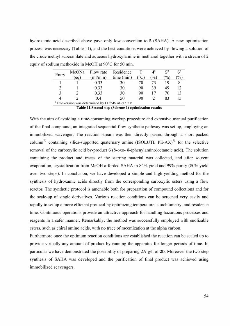
54
hydroxamic acid described above gave only low conversion to 5 (SAHA). A new optimization
process was necessary (Table 11), and the best conditions were achieved by flowing a solution of
the crude methyl suberanilate and aqueous hydroxylamine in methanol together with a stream of 2
equiv of sodium methoxide in MeOH at 90°C for 50 min.
Entry MeONa (eq)
Flow rate (ml/min)
Residence time (min)
T (°C)
4a (%)
5a (%)
6a
(%) 1 1 0.33 30 70 73 19 8 2 1 0.33 30 90 39 49 12 3 2 0.33 30 90 17 70 13 4 2 0.4 50 90 2 83 15
a Conversion was determined by LC/MS at 215 nM Table 11.Second step (Scheme 1) optimization results
With the aim of avoiding a time-consuming workup procedure and extensive manual purification
of the final compound, an integrated sequential flow synthetic pathway was set up, employing an
immobilized scavenger. The reaction stream was then directly passed through a short packed
column70 containing silica-supported quaternary amine (ISOLUTE PE-AX)71 for the selective
removal of the carboxylic acid by-product 6 (8-oxo- 8-(phenylamino)octanoic acid). The solution
containing the product and traces of the starting material was collected, and after solvent
evaporation, crystallization from MeOH afforded SAHA in 84% yield and 99% purity (80% yield
over two steps). In conclusion, we have developed a simple and high-yielding method for the
synthesis of hydroxamic acids directly from the corresponding carboxylic esters using a flow
reactor. The synthetic protocol is amenable both for preparation of compound collections and for
the scale-up of single derivatives. Various reaction conditions can be screened very easily and
rapidly to set up a more efficient protocol by optimizing temperature, stoichiometry, and residence
time. Continuous operations provide an attractive approach for handling hazardous processes and
reagents in a safer manner. Remarkably, the method was successfully employed with enolizable
esters, such as chiral amino acids, with no trace of racemization at the alpha carbon.
Furthermore once the optimum reaction conditions are established the reaction can be scaled up to
provide virtually any amount of product by running the apparatus for longer periods of time. In
particular we have demonstrated the possibility of preparing 2.9 g/h of 2b. Moreover the two-step
synthesis of SAHA was developed and the purification of final product was achieved using
immobilized scavengers.

55
Chapter 5. Reaction of Grignard reagents with carbonyl
compounds and synthesis of Tramadol

56
5.1. Addition of Grignard reagents to carbonyl compound under flow
conditions72
Organomagnesium reagents were firstly prepared over a hundred years ago by Grignard and still
occupy a central place in organic chemistry.73 They show excellent reactivity towards a wide
range of electrophiles and, for this reason, the reactions involving Grignard reagents often need to
be controlled by operating at low temperature.
The flow technique represents an innovative way to control such reactivity since its homogeneous
mixing and heat transfer narrows the temperature distribution and restricts the reaction output to
the target product.74
The addition of Grignard reagents to aldehydes and ketones under flow conditions is up-to-date
poorly exemplified in the literature. In fact, this reaction was mentioned as an application of CPC-
CYTOS microreactor system and its evolution SEQUOA with limited experimental details.75
While the reaction of a Grignard reagent with thiolactones,76 dietyl oxalate,77 and acyl chlorides78
were reported using specifically developed microreactors often operating at low temperatures.
Some examples dealing with the generation and the addition of aryllithium compounds to
electrophyles under flow conditions are present in the literature72b,79 pointing out, once more, the
advantages of the flow approach when using highly reactive species.
In the light of the broad application of Grignard reagents in organic synthesis we decided to set up
and optimise the addition of Grignard reagents to aldehydes and ketones using a commercially
available flow reactor, and to explore the reaction selectivity in the presence of reactive moieties
such as nitriles.
In a typical experiment two solutions of 4-isopropylbenzalehyde 7 and (2-methylallyl)magnesium
chloride in THF, stored under N2, were simultaneously pumped at room temperature into the flow
apparatus equipped with a 10 ml tubing reactor (Scheme 29). The reaction stream was then
directly passed through a short column containing polymer supported benzaldehyde80 for the
scavenging of the excess of Grignard reagent. The optimization of the experimental parameters
was investigated by varying the temperature of the stored solution, the residence time and the
number of Grignard equivalents (Table 12).

57
Scheme 29. Flow synthesis of secondary alcohols
Table12.Optimization of the experimental parameters
We started our investigation by pre-cooling both the stock solutions at -78°C and by varying the
residence time (entries 1 and 2). Then, the temperature of the reagent solutions was raised up to
0°C and finally to room temperature (entries 3 and 4) without observing any variation in terms of
conversion and purity in the reaction profile. This result is a direct consequence of the efficient
mixing and heat dispersion due to the high surface area-to-volume ratio in the PTFE tubing that
keeps the temperature constant minimizing the occurrence of side reactions.
The Grignard equivalents were then reduced from 2 to 1.2 (entry 5), without affecting the
conversion. For comparative purposes the same reaction was performed in traditional batch
conditions (entry 6) by adding (2-methylallyl)magnesium chloride to 4-isopropylbenzalehyde 1 at
room temperature.
The reaction mixture was thermostated and the temperature was kept constant in the course of the
reaction. After 2 hours, the desired product was detected with a conversion of 29% (UPLC-MS
215 nm) showing that, in the specified reaction conditions, the flow system is really advantageous
in term of efficacy if compared to the batch one. In order to achieve complete conversion, the
number of Grignard equivalents was risen (2 eq) and the temperature was kept at -20°C during the
Entry Grignard (eq) T (°C)a Residence time
(min) Flow rate (ml/min)
Conversion (%)b
1 2 -78 66 c 0.30 95
2 2 -78 33 0.30 96
3 2 0 33 0.30 94
4 2 r.t. 33 0.30 97
5 1.2 r.t. 33 0.30 98
6d 1.2 r.t. 120 - 29
7 d 2 -20°C 50 - 95 a Stock solution temperature. bThe conversion was determined by peak integration at 215 nm (UPLC/MS). cReaction performed using 20 ml tubing reactor. d Reaction performed in batch.

58
addition (entry 7), suggesting that the poor conversion in the previous experiment could have been
determined by Grignard degradation in the reaction mixture.
In continuous flow synthesis, scale up is generally accomplished by running the microreactor for
an extended time or by employing multi-channel parallel reactors (numbering-up process). A
demonstration of this preparative capability was readily obtained. Applying the optimized
conditions (i.e. stored solution at room temperature; flow rate: 0.30 ml/min; residence time: 33
min) 2 grams of 8a were straightforwardly produced with an output of 0.9 g/h. Yield and purity
were similar to the smaller scale proving that the reaction conditions identified for the production
of few milligrams can be directly transferred to a larger scale.
To asses the limit and the scope of this procedure, the same protocol was tested reacting different
Grignard reagents (aryl, alkyl, allyl) with 4-isopropylbenzaldehyde and acetophenone (Table 13)
on a 200 mg scale.
Entry Carbonyl compound
Grignard reagent Alcohol Yield
(%)a
1
7
8a
92
2
7
8b
93
3
7
8c
87
4
9
10a
94
5
9
10b
95

59
Entry Carbonyl compound
Grignard reagent Alcohol Yield
(%)a
6
9
10c
90
7
9
10d
95
a Isolated yields; purity > 95% (UPLC/MS) Table 13. Conversion of 4-isopropylbenzaldehyde into secondary alcohols and acetophenone into tertiary
alcohols
The desired alcohols were efficiently obtained using starting materials such as allyl (entries 1, 4),
aryl (entries 2, 5) and alkyl (entries 3, 6, 7) magnesium derivatives. In all examples the isolated
yields were excellent: of special interest are the results obtained with the hindered tert-butyl
magnesium bromide as a reagent (entries 3, 6).
To verify the effectiveness and reproducibility of the optimized protocol, the synthesis of a small
collection of secondary and tertiary alcohols was also undertaken. (4-chlorophenyl)magnesium
bromide was chosen as reference Grignard reagent and the optimized conditions were applied to
different substrates on a 200 mg scale (Table 14).
Entry Carbonyl compound Alcohol Yield (%)a
1
11
12
90
2
13
14
94
3
15
16
92

60
Entry Carbonyl compound Alcohol Yield (%)a
4 17
18
96
5 19
20
96
6
21
22
95
7
23
24
98
8
25
26
93
aIsolated yields; purity > 95% (UPLC/MS)
Table 14. Reaction of different aldehydes and ketones with (4-chlorophenyl)magnesium bromide
The formation of alcohols from aldehydes and ketones was general and occurred smoothly in the
continuous flow system. Simple aryl carbonyl compounds, besides reference substrates, (entries 1
and 6), heteroaryl aldehydes and ketones (entries 2, 3, 4 and 5) and alkyl compounds (entries 7 and
8) were suitable substrates for the reaction. All of the desired products were obtained in yields
higher than 90%, with no detection of by-products.
5.2. Flow synthesis of Tramadol72
The protocol was finally applied to the synthesis of Tramadol ((1R*,2R*)-2-
((dimethylamino)methyl)-1-(3-methoxyphenyl)cyclohexanol) 29, a well known centrally active
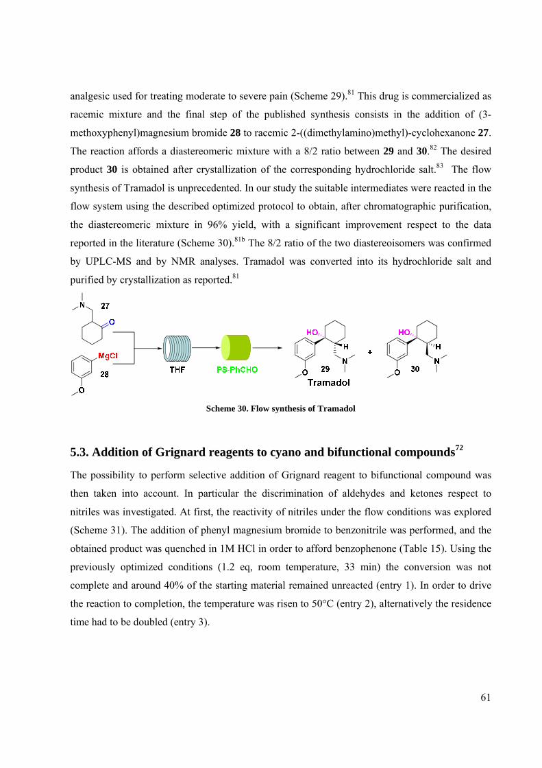
61
analgesic used for treating moderate to severe pain (Scheme 29).81 This drug is commercialized as
racemic mixture and the final step of the published synthesis consists in the addition of (3-
methoxyphenyl)magnesium bromide 28 to racemic 2-((dimethylamino)methyl)-cyclohexanone 27.
The reaction affords a diastereomeric mixture with a 8/2 ratio between 29 and 30.82 The desired
product 30 is obtained after crystallization of the corresponding hydrochloride salt.83 The flow
synthesis of Tramadol is unprecedented. In our study the suitable intermediates were reacted in the
flow system using the described optimized protocol to obtain, after chromatographic purification,
the diastereomeric mixture in 96% yield, with a significant improvement respect to the data
reported in the literature (Scheme 30).81b The 8/2 ratio of the two diastereoisomers was confirmed
by UPLC-MS and by NMR analyses. Tramadol was converted into its hydrochloride salt and
purified by crystallization as reported.81
Scheme 30. Flow synthesis of Tramadol
5.3. Addition of Grignard reagents to cyano and bifunctional compounds72
The possibility to perform selective addition of Grignard reagent to bifunctional compound was
then taken into account. In particular the discrimination of aldehydes and ketones respect to
nitriles was investigated. At first, the reactivity of nitriles under the flow conditions was explored
(Scheme 31). The addition of phenyl magnesium bromide to benzonitrile was performed, and the
obtained product was quenched in 1M HCl in order to afford benzophenone (Table 15). Using the
previously optimized conditions (1.2 eq, room temperature, 33 min) the conversion was not
complete and around 40% of the starting material remained unreacted (entry 1). In order to drive
the reaction to completion, the temperature was risen to 50°C (entry 2), alternatively the residence
time had to be doubled (entry 3).

62
Scheme 31. Addition of Grignard reagent to cyano compound
Table 15. Conversion of benzonitrile into phenylacetophenone
This interesting result let us to envisage the possibility to react aldehydes or ketones in the
presence of nitriles (Scheme 32; Table 16).
Scheme 32. Addition of Grignard reagent to bifunctional compounds
Entry Carbonyl compound Alcohol Yield
(%)
1
34
35
94
2 36
37
85
Entry Grignard (eq) T (°C) Residence time
(min) Flow rate (ml/min)
Yield (%)
1 1.2 r.t 33 0.30 59 a 2 1.2 50°C 33 0.30 90 3 1.2 r.t 66b 0.30 91
aConversion determined by peak integration at 215 nm (UPLC/MS) bReaction performed using 20 ml tubing reactor.
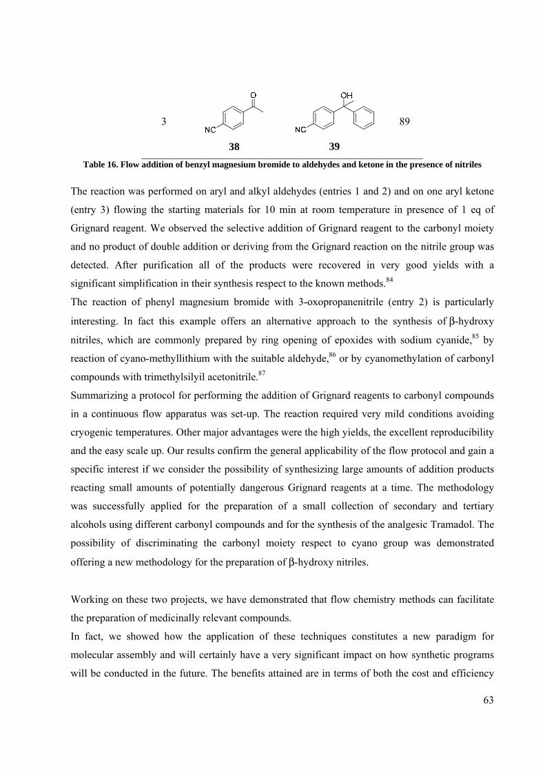
63
3
38
39
89
Table 16. Flow addition of benzyl magnesium bromide to aldehydes and ketone in the presence of nitriles
The reaction was performed on aryl and alkyl aldehydes (entries 1 and 2) and on one aryl ketone
(entry 3) flowing the starting materials for 10 min at room temperature in presence of 1 eq of
Grignard reagent. We observed the selective addition of Grignard reagent to the carbonyl moiety
and no product of double addition or deriving from the Grignard reaction on the nitrile group was
detected. After purification all of the products were recovered in very good yields with a
significant simplification in their synthesis respect to the known methods.84
The reaction of phenyl magnesium bromide with 3-oxopropanenitrile (entry 2) is particularly
interesting. In fact this example offers an alternative approach to the synthesis of β-hydroxy
nitriles, which are commonly prepared by ring opening of epoxides with sodium cyanide,85 by
reaction of cyano-methyllithium with the suitable aldehyde,86 or by cyanomethylation of carbonyl
compounds with trimethylsilyil acetonitrile.87
Summarizing a protocol for performing the addition of Grignard reagents to carbonyl compounds
in a continuous flow apparatus was set-up. The reaction required very mild conditions avoiding
cryogenic temperatures. Other major advantages were the high yields, the excellent reproducibility
and the easy scale up. Our results confirm the general applicability of the flow protocol and gain a
specific interest if we consider the possibility of synthesizing large amounts of addition products
reacting small amounts of potentially dangerous Grignard reagents at a time. The methodology
was successfully applied for the preparation of a small collection of secondary and tertiary
alcohols using different carbonyl compounds and for the synthesis of the analgesic Tramadol. The
possibility of discriminating the carbonyl moiety respect to cyano group was demonstrated
offering a new methodology for the preparation of β-hydroxy nitriles.
Working on these two projects, we have demonstrated that flow chemistry methods can facilitate
the preparation of medicinally relevant compounds.
In fact, we showed how the application of these techniques constitutes a new paradigm for
molecular assembly and will certainly have a very significant impact on how synthetic programs
will be conducted in the future. The benefits attained are in terms of both the cost and efficiency

64
gained through the avoidance of extensive purification and work-up procedures, the rapid
optimization and precise control of reaction conditions, and a reduction in manual handling.

65
Chapter 6. Flow chemistry applied to the multistep-synthesis
of natural products

66
6.1. Introduction The innovative incorporation of flow chemistry into laboratory based synthesis platforms for
increasingly complex organic transformations could represent one of the most exciting and
potentially significant developments.
Although the use of this technique could constitute a new paradigm for complex molecular
assembly and an attractive potential solution for multi-step synthesis for the possibility of
performing sequence of two or more reactions without breaking the sequence with workup and
purification, there are few examples in literature toward this type of application.
Up to now, a number of diverse organic reactions have been performed in single-step continuous-
flow systems88 but the potentiality of multi-step synthesis in a single continuous flow sequence is
not yet fully exploited as few examples are available in literature.
In fact only a small handful of multistep systems have been described which can assemble several
building blocks to more complex molecules,89 as for example the Imatinib synthesis or the
preparation of a collection of chemokine receptors that was discussed in the previous chapter.
The scarcity of reports of multistep continuous-flow syntheses is probably related to the practical
challenges that come out when such systems are assembled, which include the frequent need for
different solvents in different reactions, build-up of high back-pressure over several packed
columns in series, precipitation and clogging of tubes and columns. Another reason may be the
high-tech flavor that the field has, with discussions often focusing on lab chips and
microstructured devices, giving the impression that considerable investment is necessary to enter
into the field.
In particular the application of flow chemistry to the total synthesis of natural products has to be
still explored.
The often low availability of natural products from their sources of origin, combined with the lack
of structural analogues, creates a need for their laboratory synthesis. This is especially true if these
materials must be used as biological probes for drug discovery programs. Consequently, new
techniques are urgently required to overcome many of the bottlenecks associated with
conventional organic synthesis. Also more use of automation is needed to facilitate scale-up and to
improve the current synthesis standards in terms of reaction optimisation and product clean-up
practices.
In this light, flow chemistry could really be an answer for the solution of these problems and the
adoption of this technique could provide chemists with methods that allow for the rapid

67
production of changeling molecules in a fashion far superior to that permitted by conventional
methods.
The benefits could be in terms of both the efficiency and cost gained through the avoidance of
extensive purification and work-up procedures, the rapid optimisation and precise control of
reaction conditions, a reduction in manual handling and easy scale-up process.
6.2. State of the art
As explained before, there are just few applications of flow chemistry to the synthesis of the
natural products.
One outstanding example in this field is the preparation of the alkaloid (±)-oxomaritidine by Ley
group (Scheme 32).90
The whole seven-step synthesis was carried out through a microfluidic pumping system that
pushed the solution of reactants into a series of pre-packed columns containing immobilized
reagents, scavengers and catalysts. The first steps of the process involved the parallel synthesis of
an azide and an aldehyde, which, when combined, reacted in the presence of a polymer supported
phosphine to afford the desired imine. Reduction of the imine was followed by trifluoroacetylation
and the resulting intermediate subsequently underwent oxidative phenolic coupling, in the
presence of polymer-supported (ditrifluoroacetoxyiodo)benzene (PS-PIFA) to afford a seven-
membered tricyclic derivative. The resulting product was then passed directly into a column that
contained a polymer supported base which promoted cleavage of the amide bond, allowing for
1,4-conjugate addition to spontaneously take place, generating the target compound (±)-
oxomaritidine. The natural product was obtained with an overall yield of 40% with 90% purity
through the simple evaporation of the solvent.

68
Scheme 32. Flow multistep synthesis of (±)-oxomaritidine
The significance of this work was the development of a route that led to the desired final
compound without the need for column chromatography or the use of aqueous work-ups at any
stage. Ley group devised a flow through reaction sequence that produces the natural product in an
automated sequence from readily available starting materials in less than a day. The time saved by
using these flow through methods compared to conventional procedures (minimum four days
required for the total synthesis) is dramatic.
The same group developed also the enantioselective synthesis in flow of the neolignan natural
product grossamide.91 Lignanamides, a structurally diverse class of compounds, possess both
cyclic and acyclic structures many of which have been shown to regulate biological functions in
both plants and microorganisms making them interesting lead discovery candidates for both
pharmaceutical and agrochemical investigation.
In particular the design and validation of a flow reactor capable of synthesizing gram quantities of
compound was reported. The fully automated continuous flow reactor system was constructed
using a simple pumping arrangement with immobilized reagents packed in columns.

69
As Scheme 33 illustrates, the first step for the preparation of the natural product involved the
synthesis of amide, which was achieved via the coupling of ferulic acid and tyramine, in the
presence of polymer-supported HOBt in a first column, with the reaction progress monitored by
LC-MS. Using this approach, the authors reported an optimal conversion of amide (90% yield).
Consequently it was imperative to remove the residual tyramine (10%) before the second step. To
achieve this, the reaction mixture was passed through a second column, whereby the amine was
sequestered (providing the possibility of recycling the unreacted amine). The pure amide was then
premixed with a hydrogen peroxide-urea complex and sodium dihydrogen phosphate buffer,
before passing through a third column that contained silica-supported peroxidase (horseradish
peroxidase on silica). Collection of the reactor effluent afforded grossamide as the desired product
in excellent purity.
Scheme 33. Enantioselective flow synthesis of grossamide
Along with the ability to generate a natural product in a scalable way, this example is of particular
importance as it combines the use of supported chemicals and enzymes to induce synthetic
transformations. Due to their cost, limited stability and questionable longevity, enzymes are not
readily employed in chemical synthesis. However, through their incorporation into flow reactors,92
small quantities can be used especially for classically difficult synthetic transformations.

70
Fukase and co-workers93 employed the continuous flow dehydration of alkanols as a key reaction
step in the multikilogram synthesis of the natural product pristane (2,6,10,14-
tetramethylpentadecane), which is now widely used as an adjuvant for monoclonal antibody
production (Scheme 34). Since 2002, the availability of pristane has been limited due to the listing
of the basking shark Cetorhinus Maximus as an endangered species. With this in mind, the authors
evaluated a microfluidic approach to the large-scale synthesis of the hydrocarbon. The first two
steps of the total synthesis were performed in batch: the treatment of farnesol with MnO2 to afford
the respective aldehyde and subsequently the reaction of it with isobutylmagnesium chloride to
afford the allylic alcohol derivative.
Scheme 34. Synthesis of pristane
The alcohol (1.0 M in THF) was subsequently dehydrated under flow conditions within a micro
mixer (Comet X-01) using pTsOH·H2O in THF/toluene (0.2 to 1.0 M), a total flow rate of 600
μl/min and a reaction temperature of 90°C (Scheme 35).
The final desired product was obtained after the catalytic hydrogenation of the alkene, performed
in traditional conditions.
With the help of this flow approach, the authors were pleased to report the synthesis of pristane in
80% yield from farnesol.
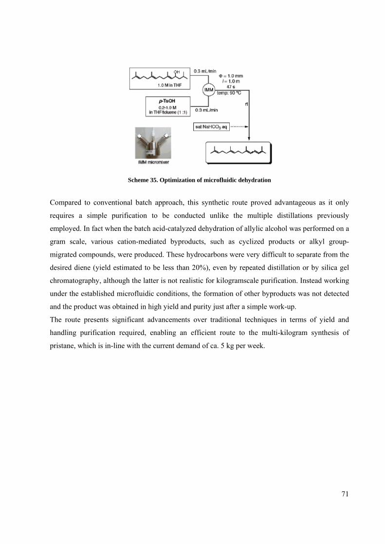
71
Scheme 35. Optimization of microfluidic dehydration
Compared to conventional batch approach, this synthetic route proved advantageous as it only
requires a simple purification to be conducted unlike the multiple distillations previously
employed. In fact when the batch acid-catalyzed dehydration of allylic alcohol was performed on a
gram scale, various cation-mediated byproducts, such as cyclized products or alkyl group-
migrated compounds, were produced. These hydrocarbons were very difficult to separate from the
desired diene (yield estimated to be less than 20%), even by repeated distillation or by silica gel
chromatography, although the latter is not realistic for kilogramscale purification. Instead working
under the established microfluidic conditions, the formation of other byproducts was not detected
and the product was obtained in high yield and purity just after a simple work-up.
The route presents significant advancements over traditional techniques in terms of yield and
handling purification required, enabling an efficient route to the multi-kilogram synthesis of
pristane, which is in-line with the current demand of ca. 5 kg per week.

72
Chapter 7. Flow synthesis of
(+)-dumetorine and natural congeners

73
7.1. Multistep synthesis of (+)-dumetorine
2-Piperidinyl alkaloids are an interesting family of natural products whose convenient synthesis
was previously described by our group.94 The proposed synthesis was based on the use of the
common electrophilic synthon 44 that, due to a stereogenic center at position 2 of the piperidine
ring and the versatile aldehyde group, is prone to a diversity-functionalization (Scheme 36). The
strategic value of this synthon consists in the gram scale availability of both its pure enantiomers
by enzyme-catalyzed preparation94a of the corresponding hydroxyl derivative 2-(2-
hydroxyethyl)piperidine.
Diels-Alder
NNH
H
HR-Li
W it tig
RCM
NH
H
Acylation
NCHO
Boc
H
Gr ignar dNMe
O
O
Gr ignar d
ReductiveAminat ion
N
OH
R1
HR2
41 R1=R2=Me α−OH (+)-sedridine42 R1=H, R2=Et β−OH (+)-2'-ethylnorlobelol43 R1=H, R2=Ph β−OH (-)-sedamine
(-)-coniine
(+)-aloperine40 (+)-dumetorine
Ref . 5 Refs. 3, 4
Ref . 1 Ref. 2
44
Scheme 36. Structures and synthetic plan of dumetorine and its congeners
(+)-dumetorine (40) was isolated in 1985 from the tubers of Dioscorea dumetorum Pax, a West
Africa yam whose extracts have found a notable use in folk medicine and arrow poisons.95
Its total batch-synthesis, recently published by our group, was reported in Scheme 37.94e
This synthetic route did not fulfil our expectations because it was affected by a very low overall
yield (<1%) showing problems at different steps of the synthetic pathway.

74
Scheme 37. Batch synthesis of (+)-dumetorine
The general interest toward the application of flow-chemistry technology to multistep synthesis
focused our attention to devise a more concise and efficient continuous synthetic route to 40 and to
its simplified natural congeners (+)-sedridine (41) and (-)-sedamine (43).
Moreover, we thought that this synthesis represents a remarkable challenge for the evaluation of
the potential benefits that continuous flow chemistry could provide to the preparation of natural
products in comparison with traditional batch techniques, also in the light of the scarce number of
studies published in this area (see Chapter 6).
Basically, we were trusting to make the most of the power of flow chemistry in terms of more
selective chemical transformation, safer handling of material and purification efficiency to
improve the entire global synthetic pathway.
We decided to assemble the target molecule according to the synthetic plan previously described
from N-Boc-2-hydroxyethylpiperidine: oxidation to aldehyde, Grignard addition, acylation and
RCM reaction, deprotection and methylation. In particular the yields of the two final steps must be
improved to obtain a satisfactory overall outcome.
In the first step of our flow sequence towards (+)-dumetorine, the pure S enantiomer N-Boc-2-(2-
hydroxyethyl)piperidine 45, obtained in gram scale by enzyme-catalyzed preparation, was
converted into the corresponding aldehyde 44 (Scheme 38).

75
Scheme 38. First step: Oxidation
The reaction was performed continuously cycling the stream of the reagent dissolved in
dichloromethane (DCM) through a glass column (Omnifit®) filled with PL-IBX Amide,96 till
complete conversion of the starting material into the desired product was obtained as detected at
UPLC/MS (Figure 25).
Starting Material
OutputPL-IBX
Figure 25. “Oxidation loop”
In order to speed up the reaction rate, the column containing the resin was heated at 45°C.
Temperature higher than 50°C, described as possible in literature,93a promoted, in our case, the
degradation of PL-IBX Amide: the presence of organic residues of the supported oxidant were
detected in the UPLC/MS chromatogram.
Starting from 800 mg of (hydroxyethyl)piperidine, after 8 hours, the pure desired aldehyde was
recovered in high yield (91%) by simple solvent evaporation (batch conditions: 6 hours, r.t., 85%
yield).
The long reaction time was intrinsically related to the use of the supported reagent and moreover
to the relatively limited residence time of the reaction mixture in contact with the resin in the
column (about 10 min for each passage). On the contrary no extensive manual purification of the
oxidation product was necessary as the only handling procedure required was the evaporation of
the reaction solvent.
In the second step, the obtained aldehyde 44 underwent Grignard addition.
The optimal conditions for this reaction were found to be 1.2 equivalents of 2-
methylallylmagnesium chloride, room temperature with a residence time of 33 min, as in the
general protocol for the addition of Grignard reagent to carbonyl compounds previously described
(Chapter 5).72

76
The THF stock solutions of 2-methylallylmagnesium chloride and 45 stored under N2 were
simultaneously pumped at room temperature into the flow apparatus (Scheme 39).
The reaction stream was then directly passed through a short column containing polymer-
supported benzaldehyde80 (2 equivalents) for the scavenging of the excess of the Grignard reagent.
Scheme 39. Second step: Grignard Addition
The reaction required very mild conditions avoiding cryogenic temperatures, necessary in the
batch protocol.94e This result is a direct consequence of the efficient mixing and heat dissipation
due to the high surface area-to-volume ratio in the PTFE tubing that keeps the temperature
constant minimizing the occurrence of side reactions.
The output of the reactor was then concentrated in vacuo and, after a aqueous work-up, was
purified by silica gel chromatography to give the final product 46 in 43% yield with a remarkable
improvement compared with the batch process (-78°C, 4h, 58% yield). It is important to underline
that this chromatography purification represented the optimal solution for the easily and clean
isolation of both the diastereoisomers (46; 47) and was the unique purification in all the process.
The effectiveness and the reproducibility of the previously optimized protocol for the Grignard
reaction was confirmed by the very high overall yield (90% for both the isolated diastereoisomers;
diastereoisomer (47) isolated in 47% yield).
The next step in the synthesis was the acylation of alcohol 46 using acryloyl chloride in presence
of a base.
Preliminary flow studies were conducted pumping the reagents dissolved in dry DCM through a
pre-packed column containing different type of polymer-supported base to promote the reaction
and trap the hydrochloric acid generated in the reaction.
All the attempts performed using either PS-DIPEA or PS-DMAP97 (6 equivalents; flow rate 0.12
ml/min; residence time ca.10 min) did not give satisfactory results.
In both cases UPLC/MS analysis showed a conversion of the starting material to the desired ester
lower than 10%.
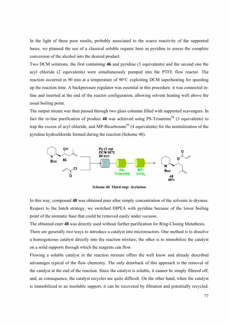
77
In the light of these poor results, probably associated to the scarce reactivity of the supported
bases, we planned the use of a classical soluble organic base as pyridine to assess the complete
conversion of the alcohol into the desired product.
Two DCM solutions, the first containing 46 and pyridine (3 equivalents) and the second one the
acyl chloride (2 equivalents) were simultaneously pumped into the PTFE flow reactor. The
reaction occurred in 90 min at a temperature of 90°C exploiting DCM superheating for speeding
up the reaction time. A backpressure regulator was essential in this procedure: it was connected in-
line and inserted at the end of the reactor configuration, allowing solvent heating well above the
usual boiling point.
The output stream was then passed through two glass columns filled with supported scavengers. In
fact the in-line purification of product 48 was achieved using PS-Trisamine98 (3 equivalents) to
trap the excess of acyl chloride, and MP-Bicarbonate99 (4 equivalents) for the neutralization of the
pyridine hydrochloride formed during the reaction (Scheme 40).
Scheme 40. Third step: Acylation
In this way, compound 48 was obtained pure after simply concentration of the solvents to dryness.
Respect to the batch strategy, we switched DIPEA with pyridine because of the lower boiling
point of the aromatic base that could be removed easily under vacuum..
The obtained ester 48 was directly used without further purification for Ring-Closing Metathesis.
There are generally two ways to introduce a catalyst into microreactors. One method is to dissolve
a homogeneous catalyst directly into the reaction mixture; the other is to immobilize the catalyst
on a solid supports through which the reagents can flow.
Flowing a soluble catalyst in the reaction mixture offers the well know and already described
advantages typical of the flow chemistry. The only drawback of this approach is the removal of
the catalyst at the end of the reaction. Since the catalyst is soluble, it cannot be simply filtered off,
and, as consequence, the catalyst recycles are quite difficult. On the other hand, when the catalyst
is immobilized to an insoluble support, it can be recovered by filtration and potentially recycled.

78
Packing a column with a supported catalyst and flowing the reaction mixture through it takes this
idea a step further. In fact, such systems have been in use industrially for decades in the form of
packed-bed reactors (PBRs), and much of the work with immobilized catalysts in microreactors is
based on this techniques.
The metathesis reaction on micro scale was previously studied by two different groups.
Kirschining and co-workers100 performed cross and ring-closing metathesis building PASSflow
reactors in which Hoveyda-catalyst was immobilized on monolithic polymeric structure.
RCM was also investigated by Trapp employing a column reactor consisted of a capillary coated
with Grubbs 2nd generation catalyst and employed an inert carrier gas (He) to transport substrates
through the reactor.101
We wanted to develop a simple protocol, which could be not only effective but also “friendly”,
easily assembled and effortless for an organic chemist.
Firstly, we performed RCM flowing the starting material in presence of dissolved 1st or 2nd
generation Grubb’s catalyst through the PTFE loop, for short time (less than 20 min) at room
temperature. These results were comparable with what previously obtained under batch conditions
(2 h, 40°C, 75% yield)94e but obviously in this way the problem of the final purification by flash
chromatography was still present.
On the basis of the PBR concept and for minimizing purification, supported Grubbs catalysts of 1st
(a) and 2nd (b) generation (Figure 26) were prepared to perform the RCM reaction flowing the
starting material through pre-packed columns., Details of the preparation and use of the supported
catalysts were described in the next Chapter.
Figure 26. Supported Grubbs Catalysts prepared
In both cases the activity of the freshly prepared catalysts was successfully verified performing
RCM reactions using the model molecule (N,N-diallyl-4-methylbenzenesulfonamide; compound
54, see Chapter 9) as RCM substrate under both standard solid-phase and flow conditions.

79
On the other hands, when the reaction was performed on the more complex and hindered
compound 48, no satisfactory results were obtained.
In fact, with catalyst (a), the RCM reaction didn’t occur and the use of the supported Grubbs 2nd
generation catalyst (b) did not give a acceptable result as well, obtaining a poor conversion (lower
than 20% after 48 hours) into the desired product.
In the light of the reported results, the preparation of PEG supported Grubbs catalyst was planned
to increase the performance in RCM maintaining the possibility of a simple catalyst recovery.
Using this strategy, differently from the use of an insoluble cross-linked polymer, the catalytic
reaction can be carried out under homogeneous conditions and then an easy separation of the
catalyst is allowed after the reaction end.102 In particular the polyether supports are most
commonly recovered by solvent promoted precipitation and filtration. PEG is usefully soluble in a
wide range of solvents including DMF, dichloromethane, toluene, acetonitrile and water while the
solvents usually used for the precipitation process are hexane, diethyl ether, tert-butylmethyl ether
(TBME), isopropyl alcohol, and cold ethanol. This type of solubility facilitates the use of PEG-
supported species for carrying out metathesis reactions that usually are performed in DCM.
A newly synthesized PEG-Supported Hoveyda catalyst (Figure 27) was prepared in collaboration
with Prof. M. Benaglia and Dr. A. Caselli (Università degli Studi di Milano) and its synthesis is
described in details in the next Chapter. This PEG-Supported catalyst is an analogue of PEG-
immobilized Ru catalysts described in literature.103
Figure 27. PEG-supported Hoveyda catalyst
This PEG-supported catalyst, led to the total conversion of compound 48 into lactone 49 (Scheme
41).

80
NBoc
O
O
N
O
O
Boc DCM 70°C50 min
PEGHoveydacatalyst
Et2O
Catalystrecovery
4995%
48
Scheme 41. Fourth step: Ring Closing Metathesis
The streams containing 48 and the PEG-Hoveyda catalyst (6%mol Ru) dissolved in dry DCM
were pumped into a PTFE loop reactor and the reaction occurred at 70°C with a residence time of
50 min. As usual the reaction conditions were optimized varying the residence time, the
temperature and the catalyst amount. The final high temperature was necessary for assess the total
conversion of the starting material in less than one hour. However the presence of DCM in the
mixture did not preclude the use of relatively high reaction temperatures which could be achieved
by the addition of a 100 psi back-pressure regulator (BPR) inserted at the end of the reactor
configuration.
The reaction output was collected into a vial containing a proper volume of diethyl ether that
allows the quantitative precipitation of the PEG-bound catalyst. The Hoveyda-catalyst was filtered
off on a solid/liquid phase separator cartridge and the desired product 49 was easily obtained by
solvent evaporation in high purity and 95% yield. Also the presence of any residue of the Hoveyda
catalyst wasn’t detected by 1H-NMR spectroscopy.
The PEG-supported Hoveyda catalyst showed high performance in our RCM reaction and
guaranteed a very simple catalyst recovery avoiding chromatographic purification. Moreover, the
recycle of the catalyst could be possible and was verified in a model reaction (the use of this
catalyst on other substrates and its recycle is fully described in the next Chapter).
A new and efficient protocol for Ring Closing Metathesis under continuous flow conditions was
developed. In fact the reaction occurred on a complex compound with high yields. Moreover the
procedure requires limited and easy manual handling operations, avoiding the use of
chromatography column.
The (+)-dumetorine batch synthesis was affected by a low yielding acid catalyzed cleavage of Boc
protecting group due to a Michael side reaction of the secondary amine on the α-β unsaturated
lactone ring. In particular, the N-Boc deprotection resulted in the isolation of small amount of
desired product 50 (10% yield) accompanied by the tricyclic by-product 51 (60% yield). Also, the

81
subsequently reductive amination resulted to be not an easy task to be managed showing a poor
yield (35%) (Scheme 42).
Scheme 42. Deprotection and reductive amination in batch.
We thought that suitable reaction conditions that permit the concomitant Boc deprotection and in
situ N-methylation could block the formation of the undesired 1,4 addition by-product.
The methylation of secondary amines via treatment with formaldehyde in the presence of formic
acid at high temperature - (Eschweiler-Clarke reaction)104 is a method of proved synthetic
utility.105 In our opinion the acidic conditions and the high reaction temperature could allow to
overcome the synthetic problem by permitting the simultaneous N-deprotection and methylation..
We then performed an unprecedented flow Eschweiler-Clarke reaction on the N-Boc protected
compound (Scheme 43).
CH3CN 140°C15 min
NCH3
O
O
CH2O +HCOOH
4092%
NBoc
O
O
SCX
49
Scheme 43. Fifth step: Concomitant Boc removal and Eschweiler-Clarke reductive amination
In particular, the solution containing 49 dissolved in CH3CN was combined with the stream of
formaldehyde and formic acid in acetonitrile at a static T-junction and entered in a pre-heated
PTFE reactor. Here the Boc removal and the reductive amination occurred at 140°C in 15 min
assessing the total conversion of the starting material in (+)-dumetorine 40.

82
As usual a backpressure regulator was essential in this procedure and was connected in-line with
the exiting reaction stream, allowing heating acetonitrile to higher temperature than its boiling
point. Usually to assess very high temperatures Eschweiler-Clarke reaction is performed in
DMSO, especially under microwave conditions.104c This solvent is not suitable for an easy
evaporation, so we decided to use CH3CN obtaining similar results and guarantying its easy
removal by vacuum.
The optimal reaction conditions were rapidly found by quickly screening various reaction
parameters such as residence times and temperature. In particular the influence of the latter on the
outcome of the reaction was evaluated and the flash heating at 140°C showed to improve the
overall yield and purity profile of this transformation. Although higher temperature resulted in
better conversions in a lower reaction time, the increasing of the temperature induced the
formation of byproducts probably due to partial degradation of the starting-material.
The final compound was finally purified by a in-line ‘catch and release’ purification. In fact the
flow stream of the newly formed 40 was directly passed through a column containing silica-
supported sulfonic acid (SCX) with any unreacted reagents simply passing through to waste. A
brief washing sequence (MeOH, 0.4 ml/min) was used to elute any residues prior to release the
product by passage of 3% NH3 in MeOH (3% NH3 solution, 0.1 ml/min). The product stream was
finally eluted and then evaporated in vacuo affording (+)-dumetorine (227 mg) with 92% yield
and purity >95% assessed by 1H NMR and UPLC-MS. Optical rotation was consistent with those
reported in literature [α]25D + 38 (c 1, CHCl3), [lit. [α] 25
D + 37 (c 1, CHCl3)].
This new flow protocol clearly shows remarkable advantages if compared to the existing
procedure consisting in two separate steps of Boc removal and reductive amination:
• Total conversion of starting material in (+)-dumetorine
• Simultaneous deprotection and methylation (2 reactions in 1 step)
• No formation of 1,4 addition by-product
Summarizing, the entire process for the multistep flow-based synthesis of (+)-dumetorine was
accomplished according to Scheme 44.

83
NBoc
OH NBoc
NBoc
OH
NBoc
O
O
MgClDCM45°C Diastereoisomeric
mixture
(44) 91%
SR
(46) 2S,2'R 43%(47) 2S,2'S 47%
(45)
Cl
O
Py (3 eq)DCM
N
O
O
Boc(48) 88%
DCM
PEGHoveydacatalyst
Et2OCH3CN
NCH3
O
OCH2O +HCOOH
(49) 95% (40) 92%
H
O
Catalystrecicle
PL-IBX THF PS-PhCHOSiO2
Column
PS-Trisamine
MP-HCO3
SCX
Scheme 44. Total synthesis of (+)-dumetorine
Our flow strategy comprised the combination of 5 separated synthetic steps linked into one
continuous sequence to devise a more concise and efficient synthetic pathway.
Remarkable results were obtained in the Grignard reaction, performed at room temperature in an
efficient and safe manner avoiding cryogenic temperature; in the RCM reaction, carried out with a
PEG-supported Hoveyda catalyst and finally in the unprecedented flow Eschweiler-Clarke N-
methylation with concomitant Boc deprotection.
Packed columns containing appropriate immobilized reagents, scavenger materials or catch and
release agents were used to minimize handling, work-up and purification and to ensure the quality
of the final product. Most of the reactions were carried out exploiting solvent superheating.
Moreover for synthesizing (+)-dumetorine, new protocols were developed for performing classical
reactions under continuous flow conditions.
What is also significant in this work is that just one product purification by flash chromatography
was necessary and no use of labour intensive techniques was required to furnish materials of
appropriate quality in order to progress to the next step in the synthesis.
This flow total synthesis also represents a significant improvement over the existing protocol. The
main advantages and improvements are listed below:
• High yields in all the performed reactions (>85%).
• Purity > 95% (LC/MS) for all intermediates and the final compound.
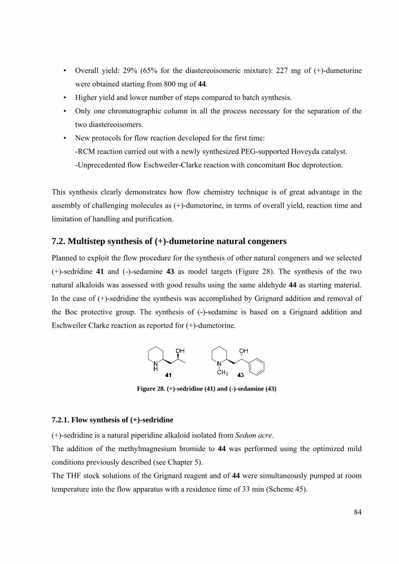
84
• Overall yield: 29% (65% for the diastereoisomeric mixture): 227 mg of (+)-dumetorine
were obtained starting from 800 mg of 44.
• Higher yield and lower number of steps compared to batch synthesis.
• Only one chromatographic column in all the process necessary for the separation of the
two diastereoisomers.
• New protocols for flow reaction developed for the first time:
-RCM reaction carried out with a newly synthesized PEG-supported Hoveyda catalyst.
-Unprecedented flow Eschweiler-Clarke reaction with concomitant Boc deprotection.
This synthesis clearly demonstrates how flow chemistry technique is of great advantage in the
assembly of challenging molecules as (+)-dumetorine, in terms of overall yield, reaction time and
limitation of handling and purification.
7.2. Multistep synthesis of (+)-dumetorine natural congeners
Planned to exploit the flow procedure for the synthesis of other natural congeners and we selected
(+)-sedridine 41 and (-)-sedamine 43 as model targets (Figure 28). The synthesis of the two
natural alkaloids was assessed with good results using the same aldehyde 44 as starting material.
In the case of (+)-sedridine the synthesis was accomplished by Grignard addition and removal of
the Boc protective group. The synthesis of (-)-sedamine is based on a Grignard addition and
Eschweiler Clarke reaction as reported for (+)-dumetorine.
Figure 28. (+)-sedridine (41) and (-)-sedamine (43)
7.2.1. Flow synthesis of (+)-sedridine
(+)-sedridine is a natural piperidine alkaloid isolated from Sedum acre.
The addition of the methylmagnesium bromide to 44 was performed using the optimized mild
conditions previously described (see Chapter 5).
The THF stock solutions of the Grignard reagent and of 44 were simultaneously pumped at room
temperature into the flow apparatus with a residence time of 33 min (Scheme 45).

85
The reaction stream was then directly passed through a short column containing polymer-
supported benzaldehyde80 for the scavenging of the excess of Grignard reagent.
Scheme 45. First step: Grignard Addition
The output of the reactor was then evaporated and, after an aqueous work-up, it was purified by
silica gel chromatography to give the distereoisomer 50 in 49% yield. Also in this case the silica
gel chromatography represented the only purification in the process and was required for the easy
isolation of both the diastereoisomers (94% for both the isolated diastereoisomers; diastereoisomer
51 isolated in 45% yield)
Such results represented an additional demonstration of the good reproducibility of the Grignard
reaction under flow reaction conditions.
Differently from (+)-dumetorine, this natural product does not presents an alkylated piperidine
ring.
The Boc removal was achieved by thermal decomposition at high temperature in acidic
conditions; two acetonitrile solutions, the first containing 50 and the second HCl (dioxane 4.0 M
solution, 1 equivalent) were simultaneously pumped into the PTFE flow reactor. The reaction
occurred in 15 min at a temperature of 70°C (Scheme 46).
Scheme 46. Second step: Deprotection
(+)-sedridine was purified by the in-line ‘catch and release’ purification. The reaction mixture was
directly passed through a column containing SCX and after a brief washing sequence (MeOH, 0.4
ml/min) the product was released by passage of 3% NH3 in MeOH (3% NH3 solution, 0.1 ml/min).

86
The deprotection occurred in 98% yield and (+)-sedridine was obtained as free base in high purity
just removing the solvent under vacuum.
In the Scheme below the complete process for the flow synthesis of (+)-sedridine (overall yield
48%) is summarized:
CH3CN 70°C15 min
HClsol 4M (dioxan)
SCX
NBoc
THF33 min
Diastereoisomericmixture
H
O
NBoc
OH
PS-PhCHO SiO2Column
MgBr
NH
OH
5049%
4198%
44
Scheme 47. Flow synthesis of (+)-sedridine
7.2.1. Flow synthesis of (-)-sedamine
(-)-sedamine, an interesting 2-piperidinyl alkaloid, was isolated in Sedum species as Lobelia
Inflata that furnished a crude extract useful for the treatment of respiratory illnesses such as
asthma, bronchitis, and pneumonia.
The formation of the alcohol from aldehyde 44 was performed as usual and occurred smoothly in
the continuous flow system. As in a typical flow experiment, the Grignard reaction was performed
using phenylmagnesium bromide in half an hour at room temperature (Scheme 48) and also in this
case the desired alcohol 52 was efficiently obtained as diastereoisomeric mixture.
Scheme 48. First step: Grignard addition
After the in-line purification with PS-benzaldehyde and aqueous work-up, the desired
diastereoisomer was isolated by chromatographic column (47% yield; diastereoisomer 46% yield).

87
As mentioned above, the methylation of the nitrogen nucleus was obtained with deprotection and
concomitant Eschweiler Clarke reaction. As for the (+)-dumetorine synthesis, the solution
containing 52 dissolved in CH3CN was combined with the stream of formaldehyde and formic
acid in acetonitrile and flowed into the PTFE reactor. Here the Boc removal and the reductive
amination occurred at 180°C in 10 min with the total conversion of the starting material into (-)-
sedamine 43 (Scheme 49).
Scheme 49. Second step: Deprotection and concomitant Eschweiler Clarke reaction
As usual a backpressure regulator was connected in-line at the end of the reactor configuration,
allowing the solvent superheating. The reaction was performed at 180°C and not at 140°C (as in
the (+)-dumetorine protocol) because a higher temperature showed to improve the overall yield
and purity of this transformation in a shorter reaction time.
(-)-sedamine was purified by the usual in-line ‘catch and release’ purification through a SCX
containing Omnifit glass column. After solvent evaporation, (-)-sedamine was obtained with 89%
yield.
Scheme 50 illustrates the total flow synthesis of (-)-sedamine:
Scheme 50. Flow synthesis of (-)-sedamine

88
The synthesis of these natural products assessed the effectiveness and reproducibility of the
protocols developed during the previous synthesis of (+)-dumetorine.

89
Chapter 8. Synthesis of supported catalysts for
Metathesis Reactions

90
8.1. Introduction
Facile catalyst separation and recycle of the catalyst are of prime importance both in industrial and
academic field. From the viewpoint of atom economy, a catalyst should ideally be completely
recoverable and reusable. In this respect, immobilized or heterogeneous catalyst offer inherent
operational and economical advantages over their homogeneous counterparts.
Key issues associated with supported catalysts are:
• preservation of high activity, (enantio-) selectivity and reaction rates observed with
homogeneous catalysts
• ease of catalyst separation
• multiple catalyst recycling
• metal- and contaminant-free final products, particularly important in pharmaceutical
chemistry
8.2. Synthesis of PS-supported Grubbs catalysts
Metathesis belongs nowadays to the most potent C–C double bond forming reactions,106 allowing
the synthesis of both well-defined, functional polymers and complex architectures including
medium-sized and large ring structures. The findings that these reactions can be carried out in an
enantioselective way107 widened the range of applications from commodity chemicals to the
synthesis of chiral compounds relevant to pharmaceutical chemistry.
As explained before, in our opinion supported Ru catalyst could offer the access to the
development of Ring Closing Metathesis under continuous flow conditions characterized by high
reaction performance, easy purification and the possibility of catalyst reusing.
On the basis of our experience in the use of polymer supported reagents and scavengers, we
thought as a first approach to prepare polymer supported Grubbs catalyst of 1st and 2nd
generation.108
Our idea was performing Ring Closing Metathesis simply passing the reaction mixture through a
column filled with a polymer supported catalyst (Scheme 51).

91
NBoc
O
O
N
O
O
Boc
DCM
SupportedGrubbs catalyst48 49
Scheme 51. Flow RCM with Solid Supported Grubbs catalyst
Furthermore, such polymer-supported catalysts seem ideally suited for recycling purposes without
the need for chromatography or aqueous work-up regime, thereby avoiding the need for removal
of heavy metals from aqueous waste. A drawback could be a lower catalytic activity than its
homogeneous counterpart.
The immobilization of metathesis catalysts on standard supports such as silica or polystyrene-
divinylbenzene (PS-DVB) has already been addressed by many groups.109
Firstly we prepared a vinyl polystyrene supported Grubbs of 1st generation described by Barrett
and co-workers.110
This polymer-bound catalyst is a 'boomerang' supported catalyst. The “boomerang” mechanism
involvs firstly the catalyst release into the solution where the RCM occurs as in the homogeneous
catalyst scenario, with concomitant reaction rate advantages, and finally the ruthenium recapture
by the styrene vinyl groups of the polymer.
Polymer-supported ruthenium catalyst was obtained by simply shaking a mixture of the Grubbs
carbene (approx. 10 mol% based on calculated vinyl resin sites) and vinyl polystyrene for 1-2 h in
CH2C12 and it was isolated as orange-brown beads by filtration. The washings from the filtration
were essentially colourless indicating complete incorporation of the Grubbs catalyst onto the
support (Scheme 52).
Scheme 52. Synthesis of vinyl polystyrene supported Grubbs of 1st generation
Polymer-supported catalyst was employed for RCM of representative diene substrate 54 (N,N-
diallyl-p-toluenesulfonamide) firstly under traditional solid phase reaction conditions (Scheme
53). Polymer-supported catalyst 53 was suspended in dichloromethane, the diene added and the
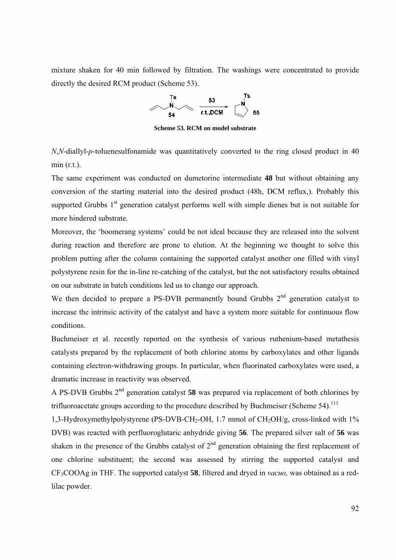
92
mixture shaken for 40 min followed by filtration. The washings were concentrated to provide
directly the desired RCM product (Scheme 53).
Scheme 53. RCM on model substrate
N,N-diallyl-p-toluenesulfonamide was quantitatively converted to the ring closed product in 40
min (r.t.).
The same experiment was conducted on dumetorine intermediate 48 but without obtaining any
conversion of the starting material into the desired product (48h, DCM reflux,). Probably this
supported Grubbs 1st generation catalyst performs well with simple dienes but is not suitable for
more hindered substrate.
Moreover, the ‘boomerang systems’ could be not ideal because they are released into the solvent
during reaction and therefore are prone to elution. At the beginning we thought to solve this
problem putting after the column containing the supported catalyst another one filled with vinyl
polystyrene resin for the in-line re-catching of the catalyst, but the not satisfactory results obtained
on our substrate in batch conditions led us to change our approach.
We then decided to prepare a PS-DVB permanently bound Grubbs 2nd generation catalyst to
increase the intrinsic activity of the catalyst and have a system more suitable for continuous flow
conditions.
Buchmeiser et al. recently reported on the synthesis of various ruthenium-based metathesis
catalysts prepared by the replacement of both chlorine atoms by carboxylates and other ligands
containing electron-withdrawing groups. In particular, when fluorinated carboxylates were used, a
dramatic increase in reactivity was observed.
A PS-DVB Grubbs 2nd generation catalyst 58 was prepared via replacement of both chlorines by
trifluoroacetate groups according to the procedure described by Buchmeiser (Scheme 54).111
1,3-Hydroxymethylpolystyrene (PS-DVB-CH2-OH, 1.7 mmol of CH2OH/g, cross-linked with 1%
DVB) was reacted with perfluoroglutaric anhydride giving 56. The prepared silver salt of 56 was
shaken in the presence of the Grubbs catalyst of 2nd generation obtaining the first replacement of
one chlorine substituent; the second was assessed by stirring the supported catalyst and
CF3COOAg in THF. The supported catalyst 58, filtered and dryed in vacuo, was obtained as a red-
lilac powder.

93
OH
F2CCF2
CF2
O OOO
O
CF2F2C
CF2
OHO
+1. aq. NaOH2. aq. AgNO3
OO
CF2F2C
CF2
OAgO
56
THF
RuCl
IMesH2Cl
PCy32. CF3COOAg, THF
1. 57, DCM RuIMesH2
O2CCF3
PCy3
O
OCF2
F2C
CF2O
O58
57
PCy3= tricyclohexylphosphine,IMesH2 = 1,3-dimesityldihydroimidazolin-2-ylidene
Scheme 54. Synthesis of PS-DVB Grubbs 2nd generation catalyst
Catalyst 58 was tested on the model substrate 54 and on our intermediate 48 under traditional solid
phase reaction conditions.
In both cases we observed just a partial conversion (about 25%) of the starting material into the
close product (from 6 to 48 h, DCM reflux).
This poor result led us to abandon the idea of testing the PS-DVB supported Grubbs 2nd generation
catalyst in flow RCM.
8.3. Synthesis of PEG-supported Hoveyda catalyst
In order to overcome the above mentioned problems encountered with PS-Grubbs catalyst, we
evaluated the application of a homogeneous PEG supported Grubbs type catalyst in order to
increase the performance in RCM maintaining the possibility of a simple catalyst recovery. PEG
has been used to immobilize metathesis catalysts in several ways.112
Taking inspiration by two works of Yao,103 a newly synthesized PEG-Supported Hoveyda catalyst
was prepared in collaboration with Prof. M. Benaglia and Dr. A. Caselli (Università degli Studi di
Milano).
Catalyst 64 was readily assembled as shown in Scheme 55.

94
Scheme 55. Synthesis of PEG-Supported Hoveyda catalyst
The isopropoxystyrene obtained from the reduction of 60, was firstly treated with succinic
anhydride in the presence of imidazole and DMAP to give the acid 61. This compound was then
coupled to PEG 5000, through the mixed acid anhydride intermediate 62 affording the PEG-bound
ligand 63 in quantitative yield based on 300 MHz 1H NMR spectroscopic analysis as well as on
the mass increase of the polymer.
Treatment of 63 with the Grubs 2nd generation catalyst in the presence of CuCl113 resulted in a
clean and quantitative exchange of the styrene ligand as determined by 1H NMR spectroscopy to
give 64 as an air stable deep green powder in 99% yield (loading 0.2 mmol/g, stable for 6 months
at r.t.).
The activity of 64 was then evaluated with the model diene 54. N,N-diallyl-p-toluenesulfonamide
underwent RCM in the presence of 3 mol% Ru of 64 in DCM at 40°C in 1 hour to give the cyclic
olefin in excellent conversion. Under flow condition the reaction took place in 20 minutes at 70°C
in DCM. The catalyst was easily recovered after precipitation with Et2O and importantly the
recycled material was reused for up to 6 cycles with only a very slight decrease in activity after
each recycling and reuse (Scheme 56; Table 17). The conversion (determined by UPLC-MS
analysis) was still exceeding 90% even after 6 consecutive cycles.

95
Cycle 1 2 3 4 5 6
Conversion (%) 100 100 100 98 94 91 Scheme 56; Table 17. Recycling and reuse of PEG-bound Ru catalyst 64 in the RCM
of test diene under flow reaction conditions
An equivalent performance was obtained with dumetorine intermediate 48. Its total conversion
into lactone 49 was assessed in 3 hours and in the presence of 6 mol% Ru of 64 in refluxing DCM.
Again the RCM reaction using this PEG-supported catalyst RCM was successfully performed
under flow condition and we observed the total conversion of our starting material in the desired
product in 50 minutes at 70°C (DCM superheating). The pure compound was simply obtained by
evaporation of the solvent after the precipitation of the catalyst in presence of Et2O.
With the aim at setting up a protocol for the RCM step of the total synthesis of (+)-Dumetorine,
we developed a stable, readily recyclable and reusable, PEG-supported Hoveyda catalyst. To
broaden the use of catalyst 64 and the reproducibility of our flow RCM protocol, in the future we
will investigate the performance of 64 in flow RCM on differently substituted dienes and on its
use in flow Cross Metathesis.

96
Chapter 9. Conclusions

97
Despite the rapid development of synthetic methodologies during last decades, chemists have been
using essentially the same equipment to run reactions for the last several hundred years.
Round-bottom flasks and complementary large-scale batch reactors remain the cores of modern
fine chemical and pharmaceutical synthesis. Using these traditional synthetic methods, organic
chemists can have access to almost any organic molecule successfully, however, it is becoming
clear that this modus operandi is not sustainable and new chemical technologies leading to more
efficient processes should be developed. Microreactors offer a realistic solution to this issue
because, as described in this thesis, they are inherently less wasteful than traditional techniques
and because they provide an unprecedented reaction control.
Continuous processing is common in bulk chemical production but is somewhat uncommon in
fine chemical and pharmaceutical synthesis.
Organic chemists have not fully embraced this technology, and just in recent years bench chemists
started the development of flow devices for designing new synthetic methodologies. Along with
the birth of new laboratory flow reactors different research groups both from academia and from
industry started the exploration of possible applications of this technique for laboratory scale
organic synthesis.
In the first part of this thesis the unique characteristics of microreactors that make them efficient
tools for organic chemistry were investigated using as models two classical, single-step, organic
transformation as the Grignard reaction and the preparation of hydroxamic acids.
These examples clearly demonstrated as reactions performed under flow conditions can become
faster, cleaner and safer. It was shown how microreactor offers a precise control of reaction
parameters including temperature, time, mixing, and permits to use small amounts of precious
compounds to rapidly screen a variety of conditions and find the optimal settings. In our
experience the use of flow technique gives access to experimental conditions that are often
inaccessible with conventional laboratory equipment, exploiting for instance the solvent
superheating.
The established protocols were successfully applied to the synthesis of SAHA and Tramadol, two
well know commercialized drugs, improving the known procedures for their synthesis
In the second part of this PhD thesis, the synthesis of more complex and synthetically challenging
natural compounds was accomplished using this technique. Up to now, the potentiality of multi-
98
step synthesis in a single continuous flow sequence is not yet fully exploited as very few examples
are available in literature.
Our synthesis clearly demonstrates how flow chemistry is of great advantage in the assembly of
molecules such as (+)-dumetorine, in terms of overall yield, reaction time and limitation of
handling, work-up and purification.
As conclusion, flow chemistry is an attractive new chemical technology for the design of
innovative protocol and processes and organic chemistry, in general, can take advantages of this
new approach.
Whether or not micro reactors will replace round bottomed flasks remains to be seen; however, the
current evolution of this technology appears promising and flow chemistry is emerging as a novel
method to build new processes in which the desired product can be obtained in higher yield,
purity, and in shorter periods of time if compared with traditional batch reactions.

99
Chapter 10. Synthesis of fluorescent
compounds for the study of microtubules

100
10.1. Introduction During the second and third year of my PhD, I spent few months in the laboratory of Prof. J. S.
Snaith in the University of Birmingham (UK) working for a common project, in a different field
respect to usual one of my thesis. This research was developed under the umbrella of the COST
Actions CM 0602 ("Inhibitors of Angiogenesis: design, synthesis and biological exploitation”).
10.2. Synthesis of fluorescent derivatives of tiocolchicine During my second year, in the framework of a wide project for the structural modification of
compounds with antitumor activity we conjugated some near infrared fluorophores to a
thiocolchicine derivative.
In literature there are few examples about the synthesis of fluorescent or radioactive derivative of
different antitubulinic compounds.114
Thiocolchicine115 differs from colchicine owing to the presence of a methylthio group instead of a
methoxy at C10 in the tropolonic ring and is readily available from colchicine (Figure 29).
Figure 29. thiocolchicine (65) and colchicine (66)
Colchicine is a plant alkaloid derived from autumn crocus (Colchicum autumnale) and is still one
of the most effective treatments to relieve the intense pain associated with an acute gout attack.
Thiocolchicine is able to inhibit microtubule dynamics, by hampering microtubule polymerisation.
The consequent microtubule paralysis blocks the release of pro-inflammatory mediators in
leukocytes and other inflammatory cells. In cancer cells microtubule-interacting drugs act as
spindle poisons, thereby blocking the cell cycle at the M phase and inducing apoptosis. This latter
feature underlies the antitumour properties belonging to such agents. However, colchicines,
thiocolchicines or analogues haven’t been extensively used as anticancer drugs, due to the extreme
toxicities and the consequent unfavorable therapeutic index noticed in preclinical experimental
models and in clinical trials.

101
The study of anticancer drugs such as thiocolchicine, taxol, epothilone, podophyllotoxin,
cephalomannine and the Vinca alkaloids is an important field of interest for our lab.
Bio-active fluorescent derivatives of those products could be a useful tool in the study of these
cellular mechanisms. In particular, in the light of the heightened interest in the use of near-infrared
(NIR) fluorescent dyes (max 700–900 nm) for in-cellular and in vivo imaging studies, we
proposed to conjugate our thiocolchicine derivative with different types of infrared fluorophores.
So, availing ourselves of the experience in this field of Prof. Snaith’s group, we have synthesized
and characterized fluorescently labeled derivatives of thiocolchicine that could be able to bind to
microtubules and have cytotoxicities similar to that of thiocolchicine.
The thiocolchicine derivative 67 was prepared in the lab of Prof. Passarella without the loss of the
original properties.
After the deprotection using TFA of this compound (95% yield; Scheme 1), the amine was then
conjugated with different fluorophores to give the fluorescently labeled derivatives (Scheme 57).
Scheme 57: Deprotection thiocolchicine derivative
Firstly we conjugated the thiocolchicine derivative with Fluorescein isothiocyanate (FITC
λex 492 nm; λem 518 nm in 0.1 M phosphate pH 8.0). We became interested in the examination of
fluorescein isothiocyanate (FITC) because (a) it is a very commonly used dye in biology; (b) its
excitation wave length (488 nm) does not interfere with that of cellular proteins; (c) it is easily
accessible and (d) it does not require sophisticated microscopic instruments.

102
O
O
O
OS
NH
O
NH
O
6NH2 +
O
O
NCS O
OHHO
O
O
O
OS
NH
O
NH
O
6
HN
O
O
O
OHHO
S
HN
DMFr.t., 12 h
68
69
Scheme 58: Synthesis of fluorescein-tagged thiocolchicine derivative
The reaction between the amino group and isothiocyanate group of fluorescein occurred in the
dark using DMF as solvent affording the desired fluorescent product 69 (5 mg scale; 80% yield;
Scheme 58).
The fluorescent-tagged product was purified by HPLC and characterized by MALDI TOF MS
(m/z 960) and 1H NMR. The purity was assessed by HPLC (purity 100%).
The second compound that we synthesized contained, as the fluorescent component, an osmium
complex.
The Os complexes were selected for the long wavelength absorption, which allows excitation with
wavelengths up to 700 nm. At these wavelengths tissue absorbance and autofluorescence are
minimal, and excitation can be accomplished with LEDs or laser diodes.
In particular we conjugated the amino compound with an osmium compound prepared by Prof.
Snaith’s group. The reaction (5 mg scale; 82% yield; Scheme 59) for the formation of the amide
70 occurred in the dark using DMF as solvent in 48 hours (24 hours at room temperature and 24
hours 60°C).

103
Scheme 59. Synthesis of osmium-tagged thiocolchicine derivative
As for the previous product, the purification of the thiocolchicine derivative labelled with the Os
fluorophore was obtained by preparative HPLC and the desired compound was characterized by
MALDI TOF (m/z 1271.4) and its purity by HPLC.
We chose NIR 797, a near-infrared cyanine dye for labeling of proteins as third fluorophore that
belongs to the class of fluorescent polymethine dyes. This class of dyes is particularly used in a
variety of biological applications because of their excellent spectral properties and
biocompatibility. The reaction (1 mg scale) was performed in the dark, in buffer pH 9.2 at room
temperature for 48 hours (Scheme 60). The formation of the desired product was detected by
analytical HPLC and MALDI-TOF (m/z 1428). In the light of the future biological tests on our
fluorescein and osmium derivatives, we’ll decide to repeat this reaction on a bigger quantity of
starting materials in order to obtain the NIR 797 labelled product 71.
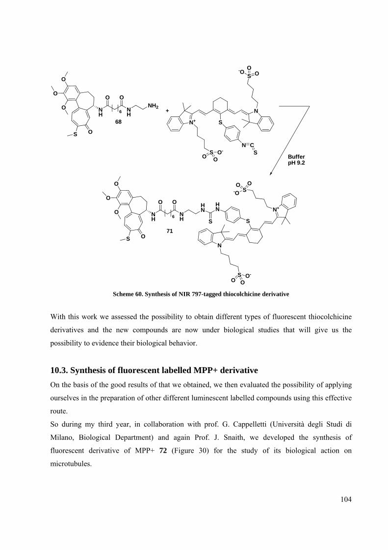
104
O
O
O
OS
NH
O
NH
O
6NH2 +
BufferpH 9.2
S
N
N
N+
S
SC
SOO-
O
OO-O
S
HN
N
N+
S
SO
-OO
O OO-
O
O
O
OS
NH
O
NH
O
6
HN
S71
68
Scheme 60. Synthesis of NIR 797-tagged thiocolchicine derivative
With this work we assessed the possibility to obtain different types of fluorescent thiocolchicine
derivatives and the new compounds are now under biological studies that will give us the
possibility to evidence their biological behavior.
10.3. Synthesis of fluorescent labelled MPP+ derivative On the basis of the good results of that we obtained, we then evaluated the possibility of applying
ourselves in the preparation of other different luminescent labelled compounds using this effective
route.
So during my third year, in collaboration with prof. G. Cappelletti (Università degli Studi di
Milano, Biological Department) and again Prof. J. Snaith, we developed the synthesis of
fluorescent derivative of MPP+ 72 (Figure 30) for the study of its biological action on
microtubules.

105
Figure 30. MPP+ (72) and MPTP (73)
MPP+ is the metabolite of MPTP 73 (Figure 30), a neurotoxin responsible of Parkinson’s
symptoms as tremors, slowness of movements, rigidity etc.116 In the cell MPP+ has two targets:
Complex I of the mitochondrial respiration and microtubules. MPP+ is able to inhibit microtubule
dynamics by hampering microtubule polymerisation. The mechanism with which MPP+
destabilizes microtubules is unknown. In particular is not clear if MPP+ interferes directly on
microtubules or if the microtubules damage is a consequence of the interaction of MPP+ with
Complex I. In fact MPP+ stops the synthesis of ATP and so of GTP in the cells interfering with
the normal activity of Complex I.
On the basis of the good results obtained previously in this field, we decided to synthesize a
fluorescently labeled derivative of MPP+ in order to prepare a useful tool for the biological study
of MPP+ action on microtubules. Availing ourselves of the experience in this field of Prof.
Snaith’s group, we projected and started to synthesize a derivative of MPP+ that could be able to
bind to microtubules and have cytotoxicities similar to MPP+ itself.
The structure of the MPP+ derivative is reported below:
We decided to put a long chain spacer between the anti-tubulinic compound and the fluorophore in
order to minimize the influence of this one on the activity MPP+ and to reduce the interaction
between the fluorescent label and microtubules.
Figure 31. 7-amino-4-methyl-3-coumarinylacetic acid
As fluorophore we chose 7-amino-4-methyl-3-coumarinylacetic acid (Figure 31) that is largely
used in the study of proteases and is characterized by excitation and emission wave lengths (UV)
that do not interfere with the markers usually employed for mitochondria and microtubules.

106
Amide links were chosen to join the three different parts of the target derivative in order to avoid
the hydrolysis phenomena that occurred into the cell environment.
We also prepared a simply modified derivative of MPP+ that will be tested on cells to analyze the
effects that could be generated by a structural modification of MPP+.
We planned the multistep synthetic route reported below (Scheme 61):
Scheme 61. Synthesis of MPP+ fluorescent derivative
The first step was the preparation of the linker with the mono-Boc protection of hexane-1,6-
diamine 76 (Scheme 62):
Scheme 62. Deprotection thiocolchicine derivative
So we performed the second step between 74 and the prepared spacer affording the desired
compound 76.
The preparation of the MPP+ nucleus was assessed by a Suzuki coupling between 76 and 77. On
this intermediate compound 78 several proofs of methylation using different solvents were tested
and the product 79 was obtained performing the reaction in presence of methyl iodide in DCM.

107
The deprotection occurred using a dioxan solution 4M of HCl in DCM affording the target
compound 80.
All the reactions were performed before on small scale (20 mg) and then repeated starting the
multistep synthesis from a bigger amount of material (800 mg).
In this way we obtained the derivative MPP+ compound that will be reacted with 7-amino-4-
methyl-3-coumarinylacetic in order to obtain the tool required for the biological studies.
Using the assessed protocol (Suzuki and consequent methylation), we also obtained the simply
modified MPP+ 81 in order to study the modification on the biological activity of the anti-
tubulinic compound that a variation in position 1 could cause.
Scheme 63. Synthesis of MPP+ simply modified derivative
With this work we projected a UV fluorescent MPP+ derivative and we started to synthesize it
(only one step to the final compound) in order to have a useful tool for biological study that could
give us more indications about its mechanism in the depolimerization of microtubules.

108
Chapter 11. Experimental section

109
11.1. Experimental protocol 1H spectra were recorded at temperature of 303 K, on a Bruker Avance2 300 Spectrometer at
300.13 MHz (1H) using DMSO-d6 as solvent. The instrument is equipped with multinuclear
inverse probe and temperature controller. Chemical shifts are expressed in ppm, utilizing the
solvent peaks as the reference and the coupling constants (J) in Hz. 13C NMR spectra were
recorded on the same instrument at 75.47 MHz using DMSO-d6 as solvent.
LC/MS analyses were performed using an UPLC/MS AquityTM combined with a Micromass
ZQTM instrument (column: Acquity BEH C18 2.1X50mm 1.7 um 35°C flow 0.6 mL/min). High
resolution electrospray mass spectra (HRESI-MS) were acquired with an FT-ICR (Fourier
Transfer Ion Cyclotron Resonance) instrument equipped with a 4.7 Tesla cryo-magnet. Samples
were dissolved in CH3CN and injected into the instrument equipped with its own ESI source.
Spectra were recorded in the HR mode with resolutions ranging from 20,000 to 30,000.
Reactions were monitored by TLC using 0.25 mm Merck silica gel plates (60 F254). Flash
chromatography was conducted using a Biotage Flash + system and prepacked silica gel columns
(KP-SIL, particle size 32-60 μm) or a Biotage Sample Processing Manifold with Isolute Flash
cartridges KP-SIL or SCX-2. Anhydrous solvents were purified by MB SPS Solvent Purification
System (MBraun).. Unless otherwise specified, solutions of common inorganic salts used in
workups are aqueous solutions. Common solvents are abbreviated as follows: DCM,
dichloromethane; DMF, N,N-dimethylformamide; DMSO, dimethyl sulfoxide; THF,
tetrahydrofuran. Poly(tetrafluoroethylene) is abbreviated in PTFE.
MW reactions were performed using a Personal Chemistry EmrysTM Optimizer apparatus.
Flow reactions were performed using a combination of R-2 Pump Module and R-4 Reactor
Module (Vapourtec®).

110
11.2. Experimental Section of Chapter 4 11.2.1 General Procedure for the synthesis of hydroxamic acid
Two 0.5M solutions of starting materials in MeOH were prepared: Reagent stock bottle A: suitable ester (1 eq); 50% aq. hydroxylamine (10 eq). Reagent stock bottle B: MeONa, 1 eq. Using the automated injection system both solutions were transferred at a constant flow rate (0.166 mL/min) onto a preheated PTFE tubing reactor (Reactor Volume 10 mL) maintained at 70°C. The reaction took place into the reactor and the product was collected in an apposite product stock bottle. The solvent was evaporated and the product was purified by the suitable reported method. The reactions were performed on 250 mg scale. For known products analytical characterization (LC-MS, 1H- and 13C-NMR) was in agreement with what reported in the cited literature.
11.2.2. Experimental for Hydroxamic Acids (compounds 2a-2j)
O
NHOH
N-Hydroxybenzamide (2a):117 Starting material: Methyl benzoate; 82% Yield; Off-white solid; Purification: Silica Cartridge (Eluent: CH2Cl2/MeOH from 95/5 to 80/20).
O
NHOH
N-Hydroxy-2-phenylacetamide (2b):117 Starting material: Ethyl 2-phenylacetate; 96% Yield; Off-white solid; Purification: Silica Cartridge (Eluent: CH2Cl2/MeOH from 95/5 to 80/20).
HN
O
NHOH
2-(Benzylamino)-N-hydroxyacetamide (2c): Starting material: Ethyl 2-(benzylamino)acetate; 96% Yield; Off-white solid; Purification: triturated with 1/1 DCM/MeOH.

111
1H NMR (300 MHz, DMSO-d6): δ (ppm) 9.18 (br. s., 2 H), 7.16- 7.36 (m, 6 H), 3.66 (s, 2 H) 3.01 (s, 2 H) 13C NMR (75 MHz, DMSO-d6): δ (ppm) 167.60 (s, 1 C), 140.26 (s, 1 C), 128.07 (s, 2 C), 127.86 (s, 2 C), 126.57 (s, 1 C), 52.36 (s, 1 C), 49.13 (s, 1 C) LC/MS (BPI): Purity 95% HRMS (ESI): Calcd for C9H13N2O2 (+1): 181.09715; Found: 181.09732 error (ppm): 0.9; Calcd for C9H13N2O2 (M+Na): 203.07910; Found: 203.07917 error (ppm): 0.7
SNH O
NHOH
O
OO
N-Hydroxy-2-(4-methoxyphenylsulfonamido)acetamide (2d):118 Starting material: Methyl 2-(4-methoxyphenylsulfonamido)acetate; 96% Yield; Off-white solid; Purification: Silica Cartridge (Eluent: CH2Cl2/MeOH from 95/5 to 80/20).
N
O
NHOH
N-Hydroxy-2-(pyridin-2-yl)acetamide (2e): Starting material: Ethyl 2-(pyridin-2-yl)acetate; 97% Yield; Pale rose solid; Purification: SCX Cartridge (Eluent: MeOH/NH4OH from 100/0 to 80/20). 1H NMR (300 MHz, DMSO-d6): δ (ppm) 10.75 (br. s., 1 H), 8.90 (br. s., 1 H), 8.37-8.53 (m, 1 H), 7.72 (td, 1 H), 7.28-7.39 (m, 1 H), 7.17-7.28 (m, 1 H), 3.51 (s, 2 H) 13C NMR (75 MHz, DMSO-d6): δ (ppm) 166.08 (s, 1 C), 155.93 (s, 1 C), 148.77 (s, 1 C), 136.50 (s, 1 C), 123.69 (s, 1 C), 121.83 (s, 1 C), 42.00 (s, 1 C) LC/MS (BPI): Purity 98% HRMS (ESI): Calcd for C7H9N2O2 (M+1): 153.06585; Found: 153.06592 error (ppm): 0.5; Calcd for C7H9N2O2 (M+Na): 175.04780; Found: 175.04792 error (ppm): 0.7
O
O
NHOH
N-Hydroxy-2-methylfuran-3-carboxamide (2f): Starting material: Methyl 2-methylfuran-3-carboxylate; 52% Yield; Yellow solid; Purification: Flash Chromatography (Eluent: CH2Cl2/MeOH 95/5). 1H NMR (300 MHz, DMSO-d6): δ (ppm) 10.69 (br. s., 1 H), 8.83 (br. s., 1 H), 7.49 (d, 1 H), 2.49 (s, 3 H)

112
13C NMR (75 MHz, DMSO-d6): δ (ppm) 161.06 (s, 1 C), 155.31 (s, 1 C), 140.65 (s, 1 C), 113.31 (s, 1 C), 108.60 (s, 1 C), 12.98 (s, 1 C) LC/MS (BPI): Purity 98% HRMS (ESI): Calcd for C6H7N1O3 (M+1): 142.04987; Found: 142.05021 error (ppm): 2.4; Calcd for C6H7N1O3 (M+Na): 164.03181; Found: 164.03211 error (ppm): 1.8
O
NHOHNHBoc
(S)-N-(tert-Butoxycarbonyl)alanine Hydroxamate (2g):118 Starting material: (S)-N-(tert-Butoxycarbonyl)alanine methyl ester; Quantitative Yield; Off-white solid; Purification: Silica Cartridge (Eluent: CH2Cl2/MeOH from 95/5 to 80/20) [ ] 14.2820 −=Dα (c 1, MeOH).
NHOH
O
NHBoc
(S)-N-(tert-Butoxycarbonyl)valine Hydroxamate (2h):119 Starting material: (S)-N-(tert-Butoxycarbonyl)valine methyl ester; 81% Yield; Off-white solid; Purification: Silica Cartridge (Eluent: CH2Cl2/MeOH from 95/5 to 80/20) [ ] 78.2820 −=Dα (c 1, MeOH). MeOH).
O
NHOHNHBoc
(S)-N-(tert-Butoxycarbonyl)phenylalanine Hydroxamate (2j):118 Starting material: (S)-N-(tert-Butoxycarbonyl)phenylalanine methyl ester; 84% Yield; Pale rose solid; Purification: Silica Cartridge (Eluent: CH2Cl2/MeOH from 95/5 to 80/20).
11.2.3. Procedure for the scale-up of the synthesis of N-hydroxy-2-phenylacetamide (2e)
General Reaction Procedure: The flow reactor was configured using a combination of R-2 Pump Module and R-4 Reactor Module (Vapourtec®). Two 0.5M solutions of starting materials in MeOH were prepared:

113
Reagent stock bottle A: ethyl 2-phenylacetate (4.7 g, 28 mmol, 1 eq); 50% aq. hydroxylamine (17 mL, 280 mmol, 10 eq). Reagent stock bottle B: MeONa (1.5 g, 28 mmol, 1 eq). Using the automated injection system, both solutions were transferred at a constant flow rate (0.166 mL/min) to a preheated PTFE tubing reactor (Reactor Volume 10 mL) maintained at 70°C. The flow reactor worked for 1.5 hours. The product was collected in a proper product stock bottle. The solvent was evaporated and the product was purified using a silica cartridge (Eluent: CH2Cl2/MeOH from 95/5 to 80/20) to obtain 4.3 g of N-hydroxy-2-phenylacetamide. Quantitative yield. OUTPUT = 2.9 g/h.
11.2.4. Procedure for the synthesis of suberoylalanide hydroxamic acid 5 (SAHA)
General Reaction Procedure Post Optimization: First Step. Preparation of Suberanilic Acid Methyl Ester 4: The flow reactor was configured using a combination of R-2 Pump Module and R-4 Reactor Module (Vapourtec®). Two 1M solutions of starting materials were prepared: Reagent stock bottle A: methyl suberoyl chloride (200 mg, 0.97 mmol, 1 eq) in THF. Reagent stock bottle B: aniline (62.4 mg, 0.97 mmol, 1 eq.); NaHCO3 (81.2 mg, 0.97 mmol, 1 eq); 1/1 THF/H2O. Using the automated injection system both solutions were transferred at a constant flow rate (3.5 mL/min) onto a PTFE tubing reactor (Reactor Volume 10 mL) at room temperature (Residence Time 1.4 min). The reaction takes place into the reactor and the product is collected in a suitable product stock bottle. The solvent was evaporated and the crude of methyl suberanilate used for the next step without further purification. Second Step. Preparation of SAHA (5): The flow reactor was configured using a combination of R-2 Pump Module and R-4 Reactor Module (Vapourtec®). Two tubing reactors (10 mL each) were installed and connected together in
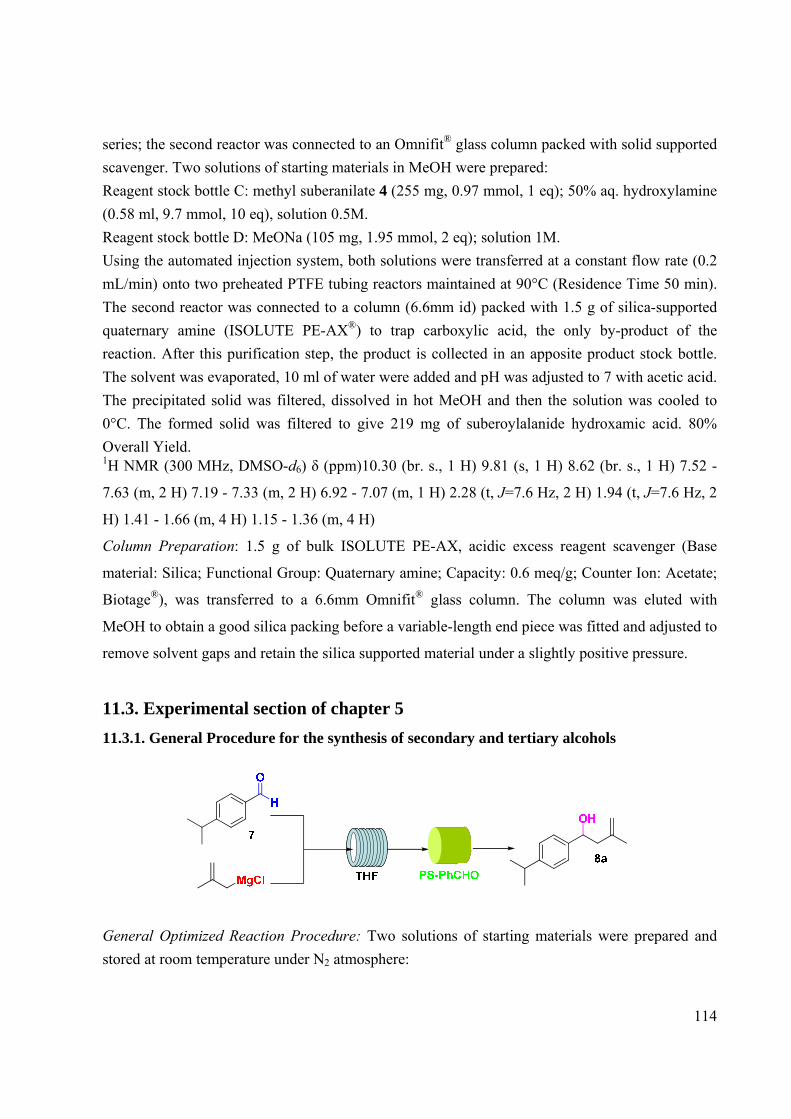
114
series; the second reactor was connected to an Omnifit® glass column packed with solid supported scavenger. Two solutions of starting materials in MeOH were prepared: Reagent stock bottle C: methyl suberanilate 4 (255 mg, 0.97 mmol, 1 eq); 50% aq. hydroxylamine (0.58 ml, 9.7 mmol, 10 eq), solution 0.5M. Reagent stock bottle D: MeONa (105 mg, 1.95 mmol, 2 eq); solution 1M. Using the automated injection system, both solutions were transferred at a constant flow rate (0.2 mL/min) onto two preheated PTFE tubing reactors maintained at 90°C (Residence Time 50 min). The second reactor was connected to a column (6.6mm id) packed with 1.5 g of silica-supported quaternary amine (ISOLUTE PE-AX®) to trap carboxylic acid, the only by-product of the reaction. After this purification step, the product is collected in an apposite product stock bottle. The solvent was evaporated, 10 ml of water were added and pH was adjusted to 7 with acetic acid. The precipitated solid was filtered, dissolved in hot MeOH and then the solution was cooled to 0°C. The formed solid was filtered to give 219 mg of suberoylalanide hydroxamic acid. 80% Overall Yield. 1H NMR (300 MHz, DMSO-d6) δ (ppm)10.30 (br. s., 1 H) 9.81 (s, 1 H) 8.62 (br. s., 1 H) 7.52 -
7.63 (m, 2 H) 7.19 - 7.33 (m, 2 H) 6.92 - 7.07 (m, 1 H) 2.28 (t, J=7.6 Hz, 2 H) 1.94 (t, J=7.6 Hz, 2
H) 1.41 - 1.66 (m, 4 H) 1.15 - 1.36 (m, 4 H)
Column Preparation: 1.5 g of bulk ISOLUTE PE-AX, acidic excess reagent scavenger (Base
material: Silica; Functional Group: Quaternary amine; Capacity: 0.6 meq/g; Counter Ion: Acetate;
Biotage®), was transferred to a 6.6mm Omnifit® glass column. The column was eluted with
MeOH to obtain a good silica packing before a variable-length end piece was fitted and adjusted to
remove solvent gaps and retain the silica supported material under a slightly positive pressure.
11.3. Experimental section of chapter 5 11.3.1. General Procedure for the synthesis of secondary and tertiary alcohols
General Optimized Reaction Procedure: Two solutions of starting materials were prepared and stored at room temperature under N2 atmosphere:

115
Reagent stock bottle A: suitable aldehyde or ketone (1 eq); 200 mg dissolved in dry THF in order to obtain a 0.25 M solution. Reagent stock bottle B: suitable Grignard reagent (THF or diethyl ether solution; 1.2 eq); dissolved in dry THF in order to obtain a 0.25 M solution. Using the automated injection system, both solutions were transferred at a constant flow rate (0.3 mL/min) onto a PTFE tubing reactor (reactor volume 10 mL) maintained at room temperature. The reactor was connected to a column (6.6mm id) packed with PS-Benzaldehyde (1 eq) to trap Grignard reagent in excess. After this purification step, the product is collected in an apposite product stock bottle. The solvent was evaporated under vacuum and the crude was partitioned between saturated solution of NH4Cl and DCM. The organic phase was dried and evaporated and the product was purified by the suitable reported method.
11.3.2. Experimental for secondary and tertiary alcohols
For known products analytical characterization (LC-MS, 1H- and 13C-NMR) was in agreement with what reported in the cited literature.
1-(4-isopropylphenyl)-3-methylbut-3-en-1-ol (8a): Starting material: 4-isopropylbenzaldehyde
7; 92% Yield; Colourless oil; Purification: Flash Chromatography (Eluent: Petroleum ether/AcOEt
9/1). 1H-NMR (300 MHz, CDCl3) δ ppm 7.33 (m, 2 H) 7.23 (m, 2 H) 4.86 - 4.98 (m, 2 H) 4.76 - 4.85
(m, 1 H) 2.93 (spt, J=7.0 Hz, 1 H) 2.39 - 2.53 (m, 2 H) 1.83 (s, 3 H) 1.27 (d, J=7.0 Hz, 6 H) 13C NMR (75 MHz, CDCl3) δ ppm 148.17 (s, 1 C) 142.59 (s, 1 C) 141.52 (s, 1 C) 126.45 (s, 2 C)
125.79 (s, 2 C) 113.81 (s, 1 C) 71.39 (s, 1 C) 48.18 (s, 1 C) 33.81 (s, 1 C) 23.99 (s, 2 C) 22.37 (s, 1
C)
HRMS (ESI): Calcd for C14H20O1Na1 (+1): 227.14064; Found: 227.14070; error (ppm): 0.4.

116
(4-chlorophenyl)(4-isopropylphenyl) (8b): Starting material: 4-isopropylbenzaldehyde 7; 93%
Yield; Off-white solid; Purification: Flash Chromatography (Eluent: Petroleum ether/AcOEt
9.5/0.5). 1H NMR (300 MHz, CDCl3) δ ppm 7.13 - 7.44 (m, 8 H) 5.80 (s, 1 H) 2.92 (spt, 1 H) 2.29 (br. s., 1
H) 1.27 (d, 6 H) 13C NMR (75 MHz, CDCl3) δ ppm 148.62 (s, 1 C) 142.37 (s, 1 C) 140.94 (s, 1 C) 133.15 (s, 1 C)
128.53 (s, 2 C) 127.83 (s, 2 C) 126.71 (s, 2 C) 126.59 (s, 2 C) 75.50 (s, 1 C) 33.81 (s, 1 C) 23.94
(s, 2 C)
HRMS (ESI): Calcd for C16H17ClO1Na1(+1): 283.08601; Found: 283.08603; error (ppm): 0.2.
1-(4-isopropylphenyl)-2,2-dimethylpropan-1-ol (8c): Starting material: 4-
isopropylbenzaldehyde 7; 87% Yield; Colourless oil; Purification: Flash Chromatography (Eluent:
Petroleum ether/AcOEt 9.8/0.2). 1H NMR (300 MHz, CDCl3) δ ppm 7.25 (m, 2 H) 7.19 (m, 2 H) 4.40 (s, 1 H) 2.92 (spt, 1 H) 1.61
(br. s., 1 H) 1.27 (d, 6 H) 0.95 (s, 9 H) 13C NMR (75 MHz, CDCl3) δ ppm 139.42 (s, 1 C) 136.28 (s, 1 C) 127.53 (s, 2 C) 125.59 (s, 2 C)
82.33 (s, 1 C) 35.64 (s, 1 C) 33.74 (s, 1 C) 25.94 (s, 3 C) 23.99 (s, 2 C)
HRMS (ESI): Calcd for C14H22O1Na1(+1): 229.15629; Found: 229.15631; error (ppm): 0.2.
4-methyl-2-phenylpent-4-en-2-ol (10a):120 Starting material: acetophenone 9; 94% Yield; Colourless oil; Purification: Flash Chromatography (Eluent: Petroleum ether/AcOEt 9.8/0.2).
OH
Cl
1-(4-chlorophenyl)-1-phenylethanol (10b):121 Starting material: acetophenone 9; 95% Yield; Colourless oil; Purification: Flash Chromatography (Eluent: Petroleum ether/AcOEt 9.8/0.2).
117
3,3-dimethyl-2-phenylbutan-2-ol (10c):122 Starting material: acetophenone 9; 90% Yield; Colourless oil; Purification: Flash Chromatography (Eluent: Petroleum ether/AcOEt 9.8/0.2).
OH
2-phenylpropan-2-ol (10d):123 Starting material: acetophenone 9; 95% Yield; Colourless oil; Purification: Flash Chromatography (Eluent: Petroleum ether/AcOEt 9.9/0.1).
(4-chlorophenyl)(phenyl)methanol (12):124 Starting material: benzaldehyde 11; 97% Yield; Colourless oil; Purification: Flash Chromatography (Eluent: Petroleum ether/AcOEt 9.7/0.3).
(4-chlorophenyl)(pyridin-2-yl)methanol (14):125 Starting material: picolinaldehyde 13; 94% Yield; Colourless oil; Purification: Silica Cartridge (Eluent: from 100% CH2Cl2 to CH2Cl2/MeOH 95/5).
1-(4-chlorophenyl)-1-(pyridin-2-yl)ethanol (16):126 Starting material: 1-(pyridin-2-yl)ethanone 15; 92% Yield; Colourless oil; Purification: Flash Chromatography (Eluent: Petroleum ether/AcOEt 9.5/0.5).

118
(4-chlorophenyl)(furan-2-yl)methanol (18): Starting material: furan-2-carbaldehyde 17; 96%
Yield; Brown oil; Purification: Flash Chromatography (Eluent: Petroleum ether/AcOEt 9.8/0.2). 1H NMR (300 MHz, DMSO-d6) δ ppm 7.56 (dd, 1 H) 7.34 - 7.50 (m, 4 H) 6.37 (dd, 1 H) 6.17 (dt,
1 H) 6.08 (d, 1 H) 5.73 (d, 1 H) 13C NMR (75 MHz, DMSO-d6) δ ppm 157.33 (s, 1 C) 142.76 (s, 1 C) 142.11 (s, 1 C) 132.24 (s, 1
C) 128.77 (s, 2 C) 128.47 (s, 2 C) 110.66 (s, 1 C) 106.97 (s, 1 C) 68.14 (s, 1 C)
HRMS (ESI): Calcd for C11H9ClO2Na1(+1): 231.01833; Found: 231.01837; error (ppm): 0.4.
O OH
Cl 1-(4-chlorophenyl)-1-(furan-2-yl)ethanol (20):127 Starting material: 1-(furan-2-yl)ethanone 19;
90% Yield; Yellow oil; Purification: Flash Chromatography (Eluent: Petroleum ether/AcOEt
9.7/0.3).
OH
Cl 1-(4-chlorophenyl)-3-methyl-1-phenylbutan-1-ol (22): Starting material: 3-methyl-1-
phenylbutan-1-one 21; 95% Yield; Colourless oil; Purification: Flash Chromatography (Eluent:
Petroleum ether/AcOEt 9.8/0.2). 1H NMR (300 MHz, DMSO-d6) δ ppm 7.39 - 7.50 (m, 4 H), 7.28 - 7.35 (m, 2 H), 7.23 - 7.28 (m, 2
H), 7.09 - 7.20 (m, 1 H), 5.50 (s, 1 H), 2.17 (d, 2 H), 1.63 (spt, 1 H), 0.77 (d, 3 H), 0.76 (d, 3 H) 13C NMR (75 MHz, DMSO-d6) δ (ppm) 149.01 (s, 1 C), 148.45 (s, 1 C), 131.01 (s, 1 C), 128.26
(s, 2 C), 128.21 (s, 2 C), 128.02 (s, 2 C), 126.54 (s, 1 C), 126.20 (s, 2 C), 76.94 (s, 1 C), 49.55 (s, 1
C), 24.91 (s, 2 C), 24.20 (s, 1 C) HRMS (ESI): Calcd for C17H19ClO1Na1(+1): 297.10166; Found: 297.10168; error (ppm): 0.2.

119
1-(4-chlorophenyl)cyclohexanol (24): Starting material: cyclohexanone 23; 98% Yield; Off-
white solid; Purification: Purification: Flash Chromatography (Eluent: Petroleum ether/AcOEt
9.5/0.5). 1H NMR (300 MHz, CDCl3) δ ppm 7.45 (m, 2 H) 7.31 (m, 2 H) 1.53 - 1.90 (m, 10 H) 1.18 - 1.43
(m, 1 H) 13C NMR (75 MHz, CDCl3) δ ppm 147.98 (s, 1 C) 132.41 (s, 1 C) 128.24 (s, 2 C) 126.17 (s, 2 C)
72.91 (s, 1 C) 38.81 (s, 2 C) 25.39 (s, 1 C) 22.08 (s, 2 C)
HRMS (ESI): Calcd for C12H15ClO1Na1(+1): 233.07036; Found: 233.07040 error (ppm): 0.4.
N
OH
Cl Bn (1-benzylpiperidin-4-yl)(4-chlorophenyl)methanol (26): Starting material: 1-benzylpiperidine-
4-carbaldehyde 25; 90% Yield; Colourless oil; Purification: Flash Chromatography (Eluent:
Petroleum ether/AcOEt 9.7/0.3). 1H NMR (300 MHz, DMSO- d6) ppm δ 7.17 - 7.42 (m, 7 H), 5.19 (d, 1 H), 4.28 (dd, 1 H), 3.39 (s,
2 H), 2.66 - 2.90 (m, 2 H), 1.61 - 1.95 (m, 3 H), 1.33 - 1.52 (m, 1 H), 1.07 - 1.33 (m, 5 H) 13C NMR (75 MHz, DMSO-d6) ppm δ 144.18 (s, 1 C), 139.24 (s, 1 C), 131.51 (s, 1 C), 129.07 (s,
2 C), 128.84 (s, 2 C), 128.53 (s, 2 C), 128.13 (s, 2 C), 127.17 (s, 1 C), 76.15 (s, 1 C), 62.86 (s, 1
C), 53.69 (s, 1 C), 53.62 (s, 1 C), 43.58 (s, 1 C), 28.63 (s, 1 C), 28.21 (s, 1 C)
HRMS (ESI): Calcd for C19H22ClONa(+1): 338.12821; Found: 338.12824 error (ppm): 0.3.

120
11.3.3. General procedure for the synthesis of Tramadol 29
Reaction Procedure: Two solutions of starting materials were prepared and stored at room
temperature under N2 atmosphere:
Reagent stock bottle A: 2–Dimethylaminomethylcyclohexanone128 (27; 1 eq); 200 mg dissolved in
dry THF in order to obtain a 0.25 M solution.
Reagent stock bottle B: 3-Methoxyphenylmagnesium bromide (THF) (28; 1.2 eq) dissolved in dry
THF in order to obtain a 0.25 M solution.
Using the automated injection system, both solutions were transferred at a constant flow rate (0.15
mL/min) onto a PTFE tubing reactor (reactor volume 10 mL) maintained at room temperature.
The reactor was connected to a column (6.6mm id) packed with PS-Benzaldehyde (1 eq) to trap
Grignard reagent in excess. After this purification step, the product is collected in an apposite
product stock bottle. The solvent was evaporated under vacuum and the crude was partitioned
between saturated solution of NH4Cl and DCM. The organic phase was dried and evaporated and
the product was purified by Flash Chromatography in order to isolate the product as a
diastereoisomeric mixture (96% yield; 8/2 ratio between 29 and 30).
Water was added and the product was extracted with ethyl ether. The extracts were dried over
sodium sulfate, filtered and evaporated in vacuum. The residue was treated ethyl ether saturated
with hydrogen chloride; the ethyl ether was evaporated in vacuo and the resulting solid was
purified by crystallization from acetone. Tramadol (29) hydrochloride was obtained as white
crystals.
For known products analytical characterization (LC-MS, 1H- and 13C-NMR) was in agreement
with what reported in the cited literature.

121
11.3.4. Procedure for the synthesis of 4-benzoylbenzonitrile 33
Reaction Procedure 1: Two solutions of starting materials were prepared and stored at room
temperature under N2 atmosphere: Reagent stock bottle A: benzonitrile (31) (200 mg; 1.94 mmol)
dissolved in 7.8 ml of dry THF. Reagent stock bottle B: phenylmagnesium bromide 32 (diethyl
ether solution 1M; 2.33 mmol, 2.33 ml) dissolved in 5.5 ml of dry THF. The system was primed
flowing dry THF for 30 minutes. Using the automated injection system, both solutions were
transferred at a constant flow rate (0.30 ml/min) onto a preheated PTFE tubing reactor (reactor
volume 10 ml) maintained at 50°C (residence time 33 min). The reactor was connected to an
Omnifit® glass column (6.6mm id) packed with PS-Benzaldehyde (loading 1.09 mmol/g; 1.78 g)
to trap Grignard reagent in excess. After this purification step, the product was directly collected
in an apposite product stock bottle containing 1M aqueous HCl. The aqueous phase was extracted
by AcOEt and the organic layer was dried over Na2SO4 and evaporated. The crude was purified by
flash chromatography (eluent: Petroleum ether/AcOEt 9.5/0.5) to obtain 378.3 mg of desired
compound as off-white powder. 90% Yield.
Reaction Procedure 2: Two solutions of starting materials were prepared and stored at room temperature under N2 atmosphere: Reagent stock bottle A: benzonitrile (31) (200 mg; 1.94 mmol) dissolved in 7.8 ml of dry THF. Reagent stock bottle B: phenylmagnesium bromide 32 (diethyl ether solution 1M; 2.33 mmol, 2.33 ml) dissolved in 5.5 ml of dry THF. The system was primed flowing dry THF for 30 minutes. Using the automated injection system, the solutions were transferred at a constant flow rate (0.30 ml/min) onto a PTFE tubing reactor (reactor volume 20 ml) maintained at room temperature (residence time 66 min). The reactor was connected to an Omnifit® glass column (6.6mm id) packed with PS-Benzaldehyde (loading 1.09 mmol/g; 1.78 g) to trap Grignard reagent in excess. After this purification step, the product was directly collected in an apposite product stock bottle containing 1M aqueous HCl. The aqueous phase was extracted by AcOEt and the organic layer was dried over Na2SO4 and evaporated. The crude was purified by flash chromatography (eluent: Petroleum ether/AcOEt 9.5/0.5) to obtain 382.1 mg of desired
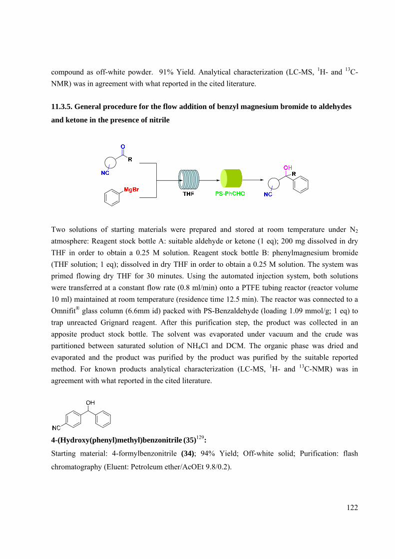
122
compound as off-white powder. 91% Yield. Analytical characterization (LC-MS, 1H- and 13C-NMR) was in agreement with what reported in the cited literature.
11.3.5. General procedure for the flow addition of benzyl magnesium bromide to aldehydes
and ketone in the presence of nitrile
Two solutions of starting materials were prepared and stored at room temperature under N2 atmosphere: Reagent stock bottle A: suitable aldehyde or ketone (1 eq); 200 mg dissolved in dry THF in order to obtain a 0.25 M solution. Reagent stock bottle B: phenylmagnesium bromide (THF solution; 1 eq); dissolved in dry THF in order to obtain a 0.25 M solution. The system was primed flowing dry THF for 30 minutes. Using the automated injection system, both solutions were transferred at a constant flow rate (0.8 ml/min) onto a PTFE tubing reactor (reactor volume 10 ml) maintained at room temperature (residence time 12.5 min). The reactor was connected to a Omnifit® glass column (6.6mm id) packed with PS-Benzaldehyde (loading 1.09 mmol/g; 1 eq) to trap unreacted Grignard reagent. After this purification step, the product was collected in an apposite product stock bottle. The solvent was evaporated under vacuum and the crude was partitioned between saturated solution of NH4Cl and DCM. The organic phase was dried and evaporated and the product was purified by the product was purified by the suitable reported method. For known products analytical characterization (LC-MS, 1H- and 13C-NMR) was in agreement with what reported in the cited literature.
4-(Hydroxy(phenyl)methyl)benzonitrile (35)129:
Starting material: 4-formylbenzonitrile (34); 94% Yield; Off-white solid; Purification: flash
chromatography (Eluent: Petroleum ether/AcOEt 9.8/0.2).

123
1.1.1. 3-Hydroxy-3-phenylpropanenitrile130 (37):
Starting material: 3-oxopropanenitrile (36); 85% Yield; Colourless oil; Purification: flash
chromatography (Eluent: Petroleum ether/AcOEt 9.9/0.1).
1.1.2. 4-(1-Hydroxy-1-phenylethyl)benzonitrile131 (39):
Starting material: 4-acetylbenzonitrile (38); 89% Yield; Off-white solid; Purification: flash
chromatography (Eluent: Petroleum ether/AcOEt 9.5/0.5).
11.4. Experimental section of chapter 7 11.4.1. Procedure for the synthesis of (+)-dumetorine
NBoc
OH NBoc
NBoc
OH
NBoc
O
O
MgClDCM45°C Diastereoisomeric
mixture
(44) 91%
SR
(46) 2S,2'R 43%(47) 2S,2'S 47%
(45)
Cl
O
Py (3 eq)DCM
N
O
O
Boc(48) 88%
DCM
PEGHoveydacatalyst
Et2OCH3CN
NCH3
O
OCH2O +HCOOH
(49) 95% (40) 92%
H
O
Catalystrecicle
PL-IBX THF PS-PhCHOSiO2
Column
PS-Trisamine
MP-HCO3
SCX
Oxidation Reaction Procedure:

124
One flow stream driven by the Vapourtec R4/R2+ containing a solution of the alcohol 45 (800 mg,
1 equiv, 3.49 mmol) in DCM was directed through a reagent column containing PL-IBX (loading
1.09 mmol/g, 5 g) heated to 45°C. The reaction was performed continuously cycling the stream
through the column until the complete conversion of the alcohol (1) into (2). A 100 psi BPR
ensured the system was pressurized, before eluting into a reaction flask. Finally, the solvent was
reduced in vacuo provided the desired 44 (725 mg, 3.19 mmol). Yield 91%. 1H NMR (300 MHz, CHLOROFORM-d) δ ppm 9.68 - 9.84 (m, 1 H), 4.78 - 4.97 (m, 1 H), 3.85 -
4.14 (m, 1 H), 2.78 - 2.88 (m, 1 H), 2.75 (ddd, J=15.26, 8.51, 3.23 Hz, 1 H), 2.55 (ddd, J=15.26,
6.46, 2.35 Hz, 1 H), 1.48 - 1.81 (m, 6 H), 1.47 (s, 9 H)
Grignard Addition Reaction Procedure:
Two flow streams driven by the Vapourtec R4/R2+; stream 1 containing a solution of 44 (725 mg,
1 equiv, 3.2 mmol) in THF (10 ml) and stream 2 containing (2-methylallyl)magnesium chloride
(0.5 M THF solution) dissolved in total 10 ml of THF (7.6 ml; 1.2 eq). These were mixed at a T-
piece before entering the CFC (volume 10 ml; 33 min residence time) maintained at RT. The
stream was then directed through a reagent column filled with PS-Benzaldehyde (loading 1.09
mmol/g; 3.5 g). A 100 psi BPR ensured the system was pressurized, before eluting into a reaction
flask. Finally, the solvent was reduced in vacuo and the crude was partitioned between water and
DCM. The organic phase was collected, dried by Na2SO3 and the solvent evaporated. The crude
was purified by cromatography column (eluent: petroleum ether/AcOEt 10/) providing 380 mg
(1.34 mmol, 42% yield) of 46 (S)-tert-butyl 2-((R)-2-hydroxy-4-methylpent-4-enyl)piperidine-1-
carboxylate and 432 mg (1.52 mmol, 48% yield) of 47 (S)-tert-butyl 2-((S)-2-hydroxy-4-
methylpent-4-enyl)piperidine-1-carboxylate. Total yield 90%. 1H NMR (300 MHz, DMSO-d6) δ ppm 4.60 - 4.80 (m, 2 H) 4.24 - 4.36 (m, 1 H) 4.29 (d, 1 H) 3.73
- 3.93 (m, 1 H) 3.45 - 3.63 (m, 1 H) 2.68 - 2.84 (m, 1 H) 1.98 - 2.25 (m, 2 H) 1.69 (s, 3 H) 1.43 -
1.65 (m, 6 H) 1.39 (s, 9 H) 1.13 - 1.35 (m, 2 H)

125
Acylation Reaction Procedure:
Two flow streams driven by the Vapourtec R4/R2+; stream 1 containing a solution of 46 (380 mg,
1 equiv, 1.34 mmol), pyridine (0.325 ml, 4.02 mmol, 3 eq) in DCM (total solution 10 ml) and
stream 2 containing acryloyl chloride (0.217 ml, 2.68 mmol, 2 eq) in DCM (total solution 10 ml).
These were mixed at a T-piece before entering the CFC (12 mL in total) for 90 min at 90°C. The
stream was then directed through a series of reagent columns beginning with PS-Trisamine
(loading 4.11 mmol/g, 1 g) and then MP-HCO3 (loading 1.8 mmol/g, 3 g). A 100 psi BPR ensured
the system was pressurized, before eluting into a reaction flask. Finally, the solvent was reduced in
vacuo providing 48 (398 mg, 1.179 mmol). Yield 88%. 1H NMR (300 MHz, DMSO-d6) δ ppm 6.30 (dd, 1 H) 6.11 (dd, 1 H) 5.92 (dd, 1 H) 4.89 - 5.13 (m,
1 H) 4.76 (s, 1 H) 4.70 (s, 1 H) 4.04 - 4.35 (m, 1 H) 3.72 - 3.97 (m, 1 H) 2.68 - 2.91 (m, 1 H) 2.39
(dd, 1 H) 2.28 (dd, 1 H) 1.85 - 2.00 (m, 1 H) 1.71 - 1.82 (m, 1 H) 1.69 (s, 3 H) 1.44 - 1.61 (m, 5 H)
1.38 (s, 9 H) 1.16 - 1.33 (m, 1 H)
Ring Closing Metathesis Procedure:
NBoc
O
O
N
O
O
Boc DCM 70°C50 min
PEGHoveydacatalyst
Et2O
Catalystrecovery
4995%
48
Two flow streams driven by the Vapourtec R4/R2+; stream 1 containing a solution of the ester 48
(398 mg, 1.179 mmol, 1 eq) in DCM (total solution 5 ml) and stream 2 containing PEG-Hoveyda
supported catalyst (loading 0.2 mmol/ g; 353 mg; 0.070 mol; 6%mol Ru) in DCM (total solution 5
ml). These were mixed at a T-piece before entering the CFC (10mL in total) for 50 min at 70°C. A
100 psi BPR ensured the system was pressurized, before eluting into a reaction flask. Diethyl ether
was added; PEG-supported catalyst was precipitated and was filtered. Finally, the solvent was
reduced in vacuo providing lactone 49 (347 mg, 1.1 mmol). Yield 95%.

126
1H NMR (300 MHz, CHLOROFORM-d) δ ppm 5.81 (s, 1 H) 4.39 - 4.58 (m, 1 H) 4.19 - 4.39 (m,
1 H) 3.86 - 4.09 (m, 1 H) 2.73 - 2.97 (m, 1 H) 2.39 - 2.68 (m, 2 H) 2.23 - 2.39 (m, 1 H) 1.99 (s, 3
H) 1.58 - 1.77 (m, 7 H) 1.47 (s, 9 H)
Eschweiler Clarke Reaction Procedure:
CH3CN 140°C15 min
NCH3
O
O
CH2O +HCOOH
4092%
NBoc
O
O
SCX
49
Two flow streams driven by the Vapourtec R4/R2+; stream 1 containing a solution of the lactone
49 (347 mg, 1.1 mmol, 1 eq) in acetonitrile (total solution 5 ml) and stream 2 containing
formaldehyde (aq. solution 36%) (343 µl, 4.49 mmol, 4 eq) and formic acid (172 µl, 4.49 mmol, 4
eq) in acetonitrile (total solution 5 ml). These were mixed at a T-piece before entering the CFC (10
mL in total) for 15 min at 140°C. The flow stream was then directed into a column containing
silica-supported sulfonic acid to perform a catch and release purification with any unreacted
reagents simply passing through to waste. A brief washing sequence (MeOH, 0.4 mL min-1) was
used to elute any residues prior to release the product by passage of NH3 in MeOH (3% NH3
solution, 0.1 mL min-1). The product stream was so eluted into a reaction flask.
Finally, the solvent was reduced in vacuo providing (+)-dumetorine 40 (227 mg, 1.01 mmol).
91%Yield. 1H NMR (300 MHz, CHLOROFORM-d) δ ppm 5.82 (s, 1 H) 4.24 - 4.79 (m, 1 H) 2.87 - 3.06 (m,
1 H) 2.42 - 2.56 (m, 1 H) 2.40 (s, 3 H) 2.15 - 2.39 (m, 5 H) 2.00 (s, 3 H) 1.57 - 1.94 (m, 4 H) 1.29
- 1.55 (m, 2 H) 13C NMR (75 MHz, CHLOROFORM-d) δ ppm 164.89 (s, 1 C) 157.12 (s, 1 C) 116.47 (s, 1 C)
73.91 (s, 1 C) 59.89 (s, 1 C) 56.87 (s, 1 C) 42.46 (s, 1 C) 37.62 (s, 1 C) 35.48 (s, 1 C) 29.93 (s, 1
C) 24.95 (s, 1 C) 23.56 (s, 1 C) 22.92 (s, 1 C)
[α]25D + 38 (c 1, CHCl3), [lit. [α] 25
D + 37 (c 1, CHCl3)]

127
11.4.2. Procedure for the synthesis of (+)-sedridine
Grignard Addition Reaction Procedure:
Two flow streams driven by the Vapourtec R4/R2+; stream 1 containing a solution of 44 (100 mg,
1 equiv, 0.44 mmol) in THF (5 ml) and stream 2 containing methylmagnesium bromide (1 M THF
solution) (0.52 ml; 1.2 eq) dissolved in total 5 ml of THF. These were mixed at a T-piece before
entering the CFC (volume 10 ml; 33 min residence time) maintained at RT. The stream was then
directed through a reagent column filled with PS-Benzaldehyde (loading 1.09 mmol/g; 400 mg). A
100 psi BPR ensured the system was pressurized, before eluting into a reaction flask. Finally, the
solvent was reduced in vacuo and the crude was partitioned between water and DCM. The organic
phase was collected, dried by Na2SO3 and the solvent evaporated. The crude was purified by
cromatography column (eluent: petroleum ether/AcOEt 10/) providing 52.1 mg (0.21 mmol, 49%
yield) of 50 and 47.9 mg (0.2 mmol, 45% yield) of 51. Total yield 94%. 1H NMR (300 MHz, CHLOROFORM-d) δ ppm 1.22 (3H, d, J=6.7 Hz) 1.42 (9H, s), 1.48– 1.80
(7H, m), 2.00 (1H, dt, J1=12 Hz, J2=2Hz ), 2.70 (1H, dt, J1=12 Hz, J2=2Hz ), 3.55 (1H, s,) 3.90 –
4.05 (1H, m), 4.42-4.54 (1H, m)
13C NMR (75 MHz, CHLOROFORM-d) δ ppm 19.1, 22.5, 25.5, 29.3, 39.4, 46.5, 63.3, 80.1,
110.6
Deprotection Reaction Procedure:

128
Two flow streams driven by the Vapourtec R4/R2+; stream 1 containing a solution of the lactone
50 (52.1 mg, 0.21 mmol, 1 eq) in acetonitrile (total solution 2.5 ml) and stream 2 containing
dioxane 4 M solution of HCl (52.5 µl, 0.21 mmol, 1 eq) in acetonitrile (total solution 2.5 ml).
These were mixed at a T-piece before entering the CFC (10 mL in total) for 15 min at 70°C. The
flow stream was then directed into a column containing silica-supported sulfonic acid to perform a
catch and release purification with any unreacted reagents simply passing through to waste. A
brief washing sequence (MeOH, 0.4 mL min-1) was used to elute any residues prior to release the
product by passage of NH3 in MeOH (3% NH3 solution, 0.1 mL min-1). The product stream was so
eluted into a reaction flask.
Finally, the solvent was reduced in vacuo providing (+)-Sedridine 41 (29.2 mg, 0.20 mmol).
98%Yield. 1H NMR (300 MHz, CHLOROFORM-d) δ ppm 1.16 (3H, d, J=5.6Hz), 1.38 – 1.56 (4H, m), 1.58
– 1.68 (3H, m), 1.76 – 1.86 (1H, m), 2.62 (1H, dt, J1 = 11.2 Hz, J2=3.7 Hz), 2.90 – 3.00 (1H, m),
3.12 (1H, d, J1 = 11, 2 Hz), 3.74 (2H, s), 4.05-4.16 (1H, m) 13C NMR (75 MHz, CHLOROFORM-d) δ ppm 23.4 24.1 25.0 30.8 43.2 46.3 54.5 64.4 [α]25
D
+26.2 (c 0,85, EtOH)
11.4.3. Procedure for the synthesis of (-)-sedamine
Grignard Addition Reaction Procedure:

129
Two flow streams driven by the Vapourtec R4/R2+; stream 1 containing a solution of 44 (100 mg,
1 equiv, 0.44 mmol) in THF (5 ml) and stream 2 containing phenylmagnesium bromide (1 M THF
solution) (0.5 ml; 1.2 eq)dissolved in total 5 ml of THF. These were mixed at a T-piece before
entering the CFC (volume 10 ml; 33 min residence time) maintained at RT. The stream was then
directed through a reagent column filled with PS-Benzaldehyde (loading 1.09 mmol/g; 480 mg). A
100 psi BPR ensured the system was pressurized, before eluting into a reaction flask. Finally, the
solvent was reduced in vacuo and the crude was partitioned between water and DCM. The organic
phase was collected, dried by Na2SO3 and the solvent evaporated. The crude was purified by
cromatography column (eluent: petroleum ether/AcOEt 10/) providing 60.5 mg (0.20 mmol, 45%
yield) of (S)-tert-butyl 2-((R)-2-hydroxy-2-phenylethyl)piperidine-1-carboxylate 52 and 64.5 mg
(0.21 mmol, 48% yield) of (S)-tert-butyl 2-((S)-2-hydroxy-2-phenylethyl)piperidine-1-carboxylate
54. Total yield 93%. 1H NMR (300 MHz, CHLOROFORM-d) δ ppm 1.45 (9H, s), 1.50 – 1.65 (6H, m), 1.80 – 1.90
(1H, m), 2.02 –2.15 (1H, m), 2.75 (1H, t, J = 14 Hz), 3.80 – 3.95 (2H, m), 4.41 (1H, bs), 4.70 –
4.78 (1H, m), 7.21-7.40 (5H, m)
13C NMR (75 MHz, CHLOROFORM-d) δ ppm 19.1, 25.4 (2C), 28.5, 29.3, 39.5, 40.5, 48.6, 72.7,
79.8, 125.7 (2C), 127.3, 128.3 (2C), 144.7, 155.4
Eschweiler Clarke Reaction Procedure:
Two flow streams driven by the Vapourtec R4/R2+; stream 1 containing a solution of 52 (60 mg,
0.2 mmol, 1 eq) in acetonitrile (total solution 2.5 ml) and stream 2 containing formaldehyde (aq.
solution 36%) (60.1 µl, 0.78 mmol, 4 eq) and formic acid (30.1 µl, 0.78 mmol, 4 eq) in acetonitrile
(total solution 2.5 ml). These were mixed at a T-piece before entering the CFC (10 mL in total) for
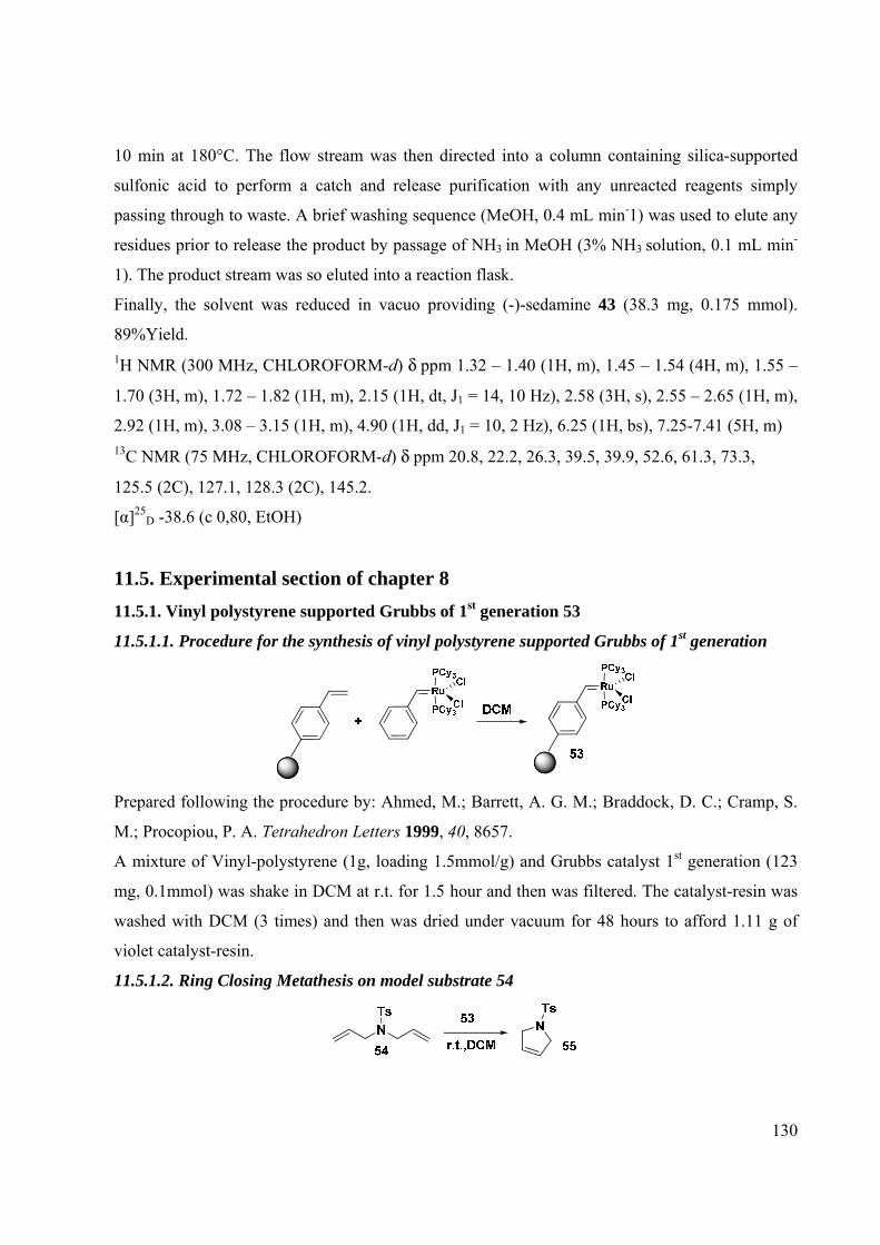
130
10 min at 180°C. The flow stream was then directed into a column containing silica-supported
sulfonic acid to perform a catch and release purification with any unreacted reagents simply
passing through to waste. A brief washing sequence (MeOH, 0.4 mL min-1) was used to elute any
residues prior to release the product by passage of NH3 in MeOH (3% NH3 solution, 0.1 mL min-
1). The product stream was so eluted into a reaction flask.
Finally, the solvent was reduced in vacuo providing (-)-sedamine 43 (38.3 mg, 0.175 mmol).
89%Yield. 1H NMR (300 MHz, CHLOROFORM-d) δ ppm 1.32 – 1.40 (1H, m), 1.45 – 1.54 (4H, m), 1.55 –
1.70 (3H, m), 1.72 – 1.82 (1H, m), 2.15 (1H, dt, J1 = 14, 10 Hz), 2.58 (3H, s), 2.55 – 2.65 (1H, m),
2.92 (1H, m), 3.08 – 3.15 (1H, m), 4.90 (1H, dd, J1 = 10, 2 Hz), 6.25 (1H, bs), 7.25-7.41 (5H, m) 13C NMR (75 MHz, CHLOROFORM-d) δ ppm 20.8, 22.2, 26.3, 39.5, 39.9, 52.6, 61.3, 73.3,
125.5 (2C), 127.1, 128.3 (2C), 145.2.
[α]25D -38.6 (c 0,80, EtOH)
11.5. Experimental section of chapter 8 11.5.1. Vinyl polystyrene supported Grubbs of 1st generation 53
11.5.1.1. Procedure for the synthesis of vinyl polystyrene supported Grubbs of 1st generation
Prepared following the procedure by: Ahmed, M.; Barrett, A. G. M.; Braddock, D. C.; Cramp, S.
M.; Procopiou, P. A. Tetrahedron Letters 1999, 40, 8657.
A mixture of Vinyl-polystyrene (1g, loading 1.5mmol/g) and Grubbs catalyst 1st generation (123
mg, 0.1mmol) was shake in DCM at r.t. for 1.5 hour and then was filtered. The catalyst-resin was
washed with DCM (3 times) and then was dried under vacuum for 48 hours to afford 1.11 g of
violet catalyst-resin.
11.5.1.2. Ring Closing Metathesis on model substrate 54

131
N,N-diallyl-4-methylbenzenesulfonamide (50mg, 0.199 mmol) was added to a suspension of PS-
Grubbs 1st generation (50 mg; 25mg of PS-Supported Grubbs 1st gen. catalyst for 0.1mmol
substrate according with the literature) in DCM. After shaking for 40 min, the reaction was
controlled by UPLC/MS and the total conversion of the starting material was observed. The resin
was filtered and the solvent removed under vacuum affording 48 mg of 55.
11.5.2. PS-DVB Grubbs 2nd generation catalyst 58
11.5.2.1. Synthesis of PS-DVB Grubbs 2nd generation catalyst
Prepared following the procedure by: (a) Yang, L.; Mayr, M.; Wurst, K.; Buchmeiser, M. R.
Chem. Eur. J. 2004, 10, 5761. (b) Halbach, T. S.; Mix, S.; Fischer, D.; Maechling, S.; Krause, J.
O.; Sievers, C.; Blechert, S.; Nuyken, O.; Buchmeiser, M. R. J. Org. Chem. 2005, 70, 4687.
Synthesis of 56
PS-CH2OH (1.7 mmol of CH2OH /g, cross-linked with 1% DVB) was suspended in dry THF and
perfluoroglutaric anhydride was added. Stirring was continued for 3h then the product was
collected by filtration and washed 3 times with THF. It was dried in vacuo to give a slightly
yellow solid 56 (2.11 g).
Synthesis of 57
Resin carboxylic acid 56 (2.11 g) was suspended in THF (18 ml) and NaOH (dissolved in water
35 ml) was added. The mixture was stirred for 3 h. The precipitated was filtered, washed 3 times
with water and re-suspended in water (25 ml). AgNO3 dissolved in water (15 ml) was added.
Stirring was continued for 2 h and the product was filtered off and washed 3 times each with
water, Et2O and pentane. Drying in vacuo gave of the product as a white solid (1.63 g).

132
Synthesis of 58
Resin silver salt 57 (500 mg) was suspended in DCM (15 ml) and Grubbs catalyst 2nd generation
(80 mg), suspended in DCM (2 ml), was added slowly. The mixture was stirred for 90 min in the
absence of light, and CF3COOAg dissolved in THF (2 ml) was added. The reaction mixture was
stirred for further 90 min. The product was filtered and washed three times with THF (10 ml) until
the filtrate was colourless. Drying in vacuo provided a red-brown powder (420 mg).
(Loading literature: 2.4mg/1g)
11.5.2.2. Ring Closing Metathesis on model substrate 54 and on 48
To a solution of N,N-diallyl-4-methylbenzenesulfonamide 54 (20 mg, 0.080 mmol) dissolved in 1
ml of dry DCM, PS-Grubbs 2nd gen. catalyst was added (20mg, following the ratio reported in
literature). The mixture was stirred at 55°C under N2 by SynCor thermo shaker apparatus for 6 hr.
UPLC/MS showed a conversion of 20%.
To a solution of tert-butyl 2-(2-(acryloyloxy)-4-methylpent-4-enyl)piperidine-1-carboxylate 48
(20mg, 0.059 mmol) dissolved in 1 ml of dry DCM, resin catalyst Grubbs 2nd gen. (50 mg,
following the ratio reported in literature) was added. The mixture was stirred at 55°C under N2 by
SynCor thermo shaker apparatus for 48 hours. The conversion was about 30% (UPLC/MS
analysis).
11.5.3. PEG-supported Hoveyda catalyst
All PEG samples were melted at 80°C in vacuum for 30 min before use to remove traces of
moisture. After reaction PEG-supported product purification involved evaporation of the reaction
solvent in vacuum and addition of the residue dissolved in a few ml of DCM to diethylether (50
ml g−1 of polymer), the obtained suspension was filtered through a sintered glass filter, and the
solid repeatedly washed on the filter with diethylether (up to 100 mL per gram of polymer,
overall).

133
The yields of the PEG-supported compounds were determined by weight with the assumption that
Mw is 5000 Da for the PEG fragment. The Mw actually ranged from 4500 to 5500. The indicated
yields were for pure compounds. The purity of these compounds was determined by 1H NMR
analysis in CDCl3 at 300 MHz with pre-saturation of the methylene signals of the polymer at
δ=3.63. In recording the NMR spectra, a relaxation time of 6 s and an acquisition time of 4 s were
used to ensure complete relaxation and accuracy of the integration. The relaxation delay was
selected after T1 measurements. The integration of the signals of the PEG CH2OCH3 fragment at
δ=3.30 and 3.36 were used as internal standard. The estimated integration error was +5%. For
intermediates analytical characterization (LC-MS, 1H- and 13C-NMR) was in agreement with what
reported in the cited literature.
11.5.3.1. Procedure for the synthesis of PEG-supported Hoveyda catalyst
Synthesis of 60103:
Step 1:
A mixture of methyl 3-formyl-4-hydroxybenzoate 59 (900 mg, 4.99 mmol), 2-iodopropane (0.995
ml, 9.98 mmol), Cs2CO3 (650.0 mg, 1.99 mmol) (1.379 g, 9.98 mmol) and K2CO3 in 20 ml of

134
DMF was stirred at room temperature under nitrogen atmosphere for 7 hours. The solvent was
removed under vacuum and the crude was partitioned between water and DCM. The organic phase
was dried and the solvent was removed under vacuum. The crude was purified on a pad of silica
gel (eluent hexane/AcOEt 9/1) affording 1100 mg of desired compound. Quantitative yield.
Step 2:
The phosphonium salt (3.53 g, 9.90 mmol) was dissolved in anhydrous toluene (25 ml) and the
resulting suspension was stirred and treated with KHMDS (1.97g, 9.90 mmol; dissolved in 25 ml
of toluene) affording a brilliant yellow suspension.
After 90 minutes, the reaction mixture was cooled to -78°C and a solution of methyl 3-formyl-4-
isopropoxybenzoate (1.1 g, 4.95 mmol) dissolved in toluene (20 ml) was added dropwise. The
temperature was slowly warmed to room temperature in 1 hour and stirred at r.t. for 30 minutes.
The reaction was quenched with 1N HCl at 0°C and then the solvent was removed under vacuum.
The crude was partitioned between NH4Cl saturated solution and AcOEt. The organic phase was
dried over Na2SO4 and then evaporated. The crude was purified by Flash Chromatography
(eluent: Hexane/AcOEt 9.5/0.5) affording 926 mg of desired compound. Yield 85%.
Synthesis of 61103:
Step 1:
Methyl 4-isopropoxy-3-vinylbenzoate 60 (926 mg, 4.20 mmol) was dissolved in anhydrous THF
(10 ml). The reaction mixture was cooled to -0°C and LiAlH4 (160 mg, 4.20 mmol) was added
portion wise. The temperature was slowly warmed to room temperature and stirred at r.t. for 1
hour. The reaction was quenched with water at 0°C and then the solvent was removed under
vacuum. The crude was partitioned between water and DCM. The organic phase was dried over
Na2SO4 and then evaporated. The crude was purified by Flash Chromatography (eluent:
Hexane/AcOEt 8/2) affording 750 mg of desired compound. Yield 93%.
Step 2:

135
(4-isopropoxy-3-vinylphenyl)methanol 60 (750 mg, 3.9 mmol) was dissolved in anhydrous DCM
(20 ml). DMAP (180 mg, 1.56 mmol), imidazole 315 mg, 4.68 mmol) and succinic anhydride (780
mg, 7.8 mmol) were added portion wise. The reaction mixture was stirred at r.t. for 1 night. The
solvent was removed under vacuum. The crude was purified by Flash Chromatography (eluent:
Hexane/AcOEt 1/1) affording 683 mg of the desired compound 61 as white powder . Yield 60%.
Synthesis of 62103:
5-(4-isopropoxy-3-vinylbenzyloxy)-5-oxopentanoic acid 61 (150 mg, 0.51 mmol) was dissolved in
dry diethyl ether (10 mL) under nitrogen and trimethylacetyl choride (63.2 µl, 0.51 mmol) and
triethylamine (52.5 µl, 0.51mmol) were added consecutively to the stirred solution cooled to -
78°C. The cold bath was removed and the solution warmed to RT was filtered and solvent
removed under reduced pressure. The mixed anhydride 62 as a viscous colourless oil (191 mg)
was subsequently used without further purification. Quantitative yield.
Synthesis of 63:
TOA, DMAPDCM
PEG 5000O
O
O
O
O
OO
O
O
O
OO
On62 63
PEG 5000 (1.25 g, 0.25 mmol) was dried in oven for 2 hours and then dissolved in dry DCM (2
ml) under nitrogen atmosphere. TOA (180 mg, 0.51 mmol) was added. The reaction mixture was
cooled at 0°C and then 4-(4-isopropoxy-3-vinylbenzyloxy)-4-oxobutanoic pivalic anhydride 62
(191 mg, 0.51 mmol) dissolved in dry DCM (2 ml) and DMAP (15 mg, 0.12 mmol) were added.
The cold bath was removed and the solution allowed to warm to room temperature and stirred for
21 hours at r.t. The solution was concentrated under vacuum and Et2O was added. PEG-bound
ligand was precipitated from the organic solution and filtered under vacuum obtaining 1.2 g of

136
PEG-bound ligand. PEG-bound ligand was dried in oven for 1 hour. 1H-NMR confirmed that the
desired product 63 was obtained with a loading of 0.2mmol/g. Quantitative yield. 1H NMR (300 MHz, CHLOROFORM-d) δ ppm 1.35 (6 H, d, J= 6.8 Hz), 2.63 (4H, d, J= 7.1 Hz ),
3.30 (2H, m, MeOCH2PEG), 3.36 (3H, s, MeOPEG), 4.70 (1H, sept, J = 6.8 Hz), 5.20 (2H, s),
5.34 (1H, dd, Jtrans=10.0 Hz, Jgem=2.1Hz ), 5.44 (1H, dd, Jcis=16.8 Hz, Jgem=2.1Hz), 6.87 (2H, m),
6.90 (1H, dd, Jtrans=10.0 Hz, Jcis=16.8 Hz), 7.11 (1H, s)
Synthesis of 64 :
Grubbs 2^ gen.CuCl,DCM, 40°CPEG
PEGO
O
O
O
O O
O
O
O
O
Ru ClSIMes
Cl
64
Grubbs 2^ Generation Catalyst ( 204 mg, 0.24mmol) and CuCl ( 24.9 mg, 0.24mmol) were
weighed into a 20 ml round bottom flask under nitrogen atmosphere and dissolved in 5 ml of
CH2Cl2. PEG-bound ligand (1.2 g, loading 0.2mmol/g) was cannulated into the resulting deep red
solution in 5 ml of CH2Cl2 at r.t. The flask was equipped with a condenser, and the solution was
stirred at 40 °C for 1 h. From this point forth, all manipulations were carried out in air with
reagent-grade solvents. The reaction mixture was concentrated in vacuo to a dark brown solid
residue. The unpurified material was dissolved in a minimal volume of 1:1 pentane/ CH2Cl2 and
then Et2O was added. PEG-Hoveyda catalyst was precipitated from the organic solution and
filtered under vacuum. PEG-Hoveyda catalyst afforded as an air stable deep green powder (1.2 g).
Clean and quantitative exchange of the styrene ligand was judged by 1H NMR spectroscopy.
Quantitative yield (loading 0.2 mmol/g). 1H NMR (300 MHz, CHLOROFORM-d) δ ppm 1.35 (6 H, d, J= 6.8 Hz), 2.58 (4H, d, J= 7.1 Hz ),
3.30 (2H, m, MeOCH2PEG), 3.36 (3H, s, MeOPEG), 4.70 (1H, sept, J = 6.8 Hz), 5.20 (2H, s),
6.80 (2H, m), 6.88 (1H, s), 7.11 (1H, s)
11.5.3.2. Flow RCM on model substrate 54 using PEG-supported Hoveyda catalyst, its recycle
and reuse

137
Two flow streams driven by the Vapourtec R4/R2+; stream 1 containing a solution of 54 (50 mg,
0.2 mmol, 1 eq) in DCM (total solution 2 ml) and stream 2 containing PEG-Hoveyda supported
catalyst (loading 0.2 mmol/ g; 29.9 mg; 0.0055 mol; 3%mol Ru) in DCM (total solution 2 ml).
These were mixed at a T-piece before entering the CFC (10 ml in total) for 20 min at 70°C. A 100
psi BPR ensured the system was pressurized, before eluting into a reaction flask. Diethyl ether was
added; PEG-supported catalyst was quantitatively precipitated and was filtered. Finally, the
solvent was reduced in vacuo providing 55 (49 mg; 0.2 mmol). Yield 100%. The same procedure
was repeated 6 times obtaining the following results:
Cycle 1 2 3 4 5 6
Conversion (%) 100 100 100 98 94 91

138
Chapter 12. Bibliography

139
1 Kirschning, A.; Solodenko W.; Mennecke K. Chem. Eur. J. 2006, 12, 5972. 2 Battacharyya, S. Curr. Opin. Drug Discov. Dev.2004, 7, 752. 3 Kappe, C.O.; Stadler, A. Microwaves in Organic and Medicinal Chemistry. Wiley–VCH, Weinheim, 2004. 4 Kappe, C.O. Angew. Chem. Int. Ed. 2004, 43, 6250. 5 Leadbeater, N.E.; Marco, M. Org. Lett.2002, 4, 2973. 6 Kappe, C.O.; Dallinger, D. Nat. Rev. Drug Discov. 2006, 5, 51. 7 (a) Caddik, S. Tetrahedron 1995, 51, 10403; (b) Lidstrom, P.; Tierney, J.; Wathey, B.; Westman, J. Tetrahedron
2001, 57, 9225. 8 (a) Loupy, A.; Petit, A.; Hamelin, J.; Texier-Boullet, F.; Jacquault, P.; Mathe, D. Synthesis 1998, 9, 1213; (b)
Mortoni, A.; Martinelli, M.; Piarulli, U.; Regalia, N.; Gagliardi, S. Tetrahedron Lett. 2004, 45, 6623. 9 Bhattacharyya, S. Mol. Divers. 2005, 9, 253. 10 Stadler, A.; Yousefi, B. H:; Dallinger, D.; Walla, P.; Van der Eycken, E.; Kaval, N.; Kappe, C.O. Org. Process Res.
Dev. 2003, 7, 707. 11 Marquié, J.; Salmoria, G.; Poux, M.; Laporterie, A.; Dubac, J.; Roqueset, N. Ind. Eng. Chem. Res. 2001, 40, 4485. 12 Geyer, K.; Jeroen, D. C.; Seeberger, P. H. Chem. Eur. J. 2006, 12, 8434. 13 Frederickson, C. K.; Fan, Z. H. Lab Chip 2004, 4, 526. 14 Laminar flow, sometimes known as streamline flow, occurs when a fluid flows in parallel layers, with no disruption
between the layers. In fluid dynamics, laminar flow is a flow regime characterized by high momentum diffusion and low momentum convection. It is the opposite of turbulent flow.
15 (a) McDonald, J. C.; Duffy, D. C.; Anderson, J. R.; Chiu, D. T.; Wu, H. K.; Schueller, O. J. A.; Whitesides, G. M. Electrophoresis 2000, 21, 27; (b) Jorgenson, J. W.; Lukacs, K. D. Anal. Chem. 1981, 53, 1298; (c) Li, D. Electrokinetics in microfluidics Elsevier, 2004, Vol.2.
16 Lainchbury, M. D.; Medley, M. I.; Taylor, P. M.; Hirst, P.; Dohle, W.; Brooker-Milburn, K. I. J. Org. Chem. 2008, 73, 6497.
17 Jas, G.; Kirschning, A. Chem. Eur. J. 2003, 9, 5708. 18 Jahnisch, K.; Hessel, V.; Lowe, H.; Baerns, M. Angew. Chem. Int. Ed. 2004, 43, 406. 19 Schwalbe, T.; Autze, V.; Wille, G. Chimia 2002, 56, 636. 20 Pennemann, H.; Watts, P.; Haswell, S. J.; Hessel, V.; Lowe, H. Org. Process Res. Dev. 2004, 8, 422. 21 (a) Watts, P.; Wiles, C.; Haswell, S. J.; Pombo-Villar, E.; Styring, P. Chem. Commun. 2001, 990; (b) Watts, P.;
Wiles, C.; Haswell, S. J.; Pombo-Villar, E. Tetrahedron 2002, 58, 5427. 22 Greenway, G. M.; Haswell, S. J.; Morgan, D. O.; Skelton, V.; Styring, P. Sensors Actuators B 2000, 63, 153. 23 Wiles, C.; Watts, P.; Haswell, S. J.; Pombo-Villar, E. Lab Chip 2002, 2, 62. 24 Ley, S. et al. Org. Process Res. Dev. 2007, 11, 458 25 Ducry, L.; Roberge, D. M. Angew. Chem. Int. Ed. 2005, 44, 7972. 26 Van der Linden, J. J. M.; Hilberink, P. W.; Kronenburg, C. M. P.; Kemperman, G. J. Org. Process Res. Dev. 2008,
12, 911. 27 Zhang,X.; Stefanick, S.; Villani, F. J. Org. Process Res.Dev. 2004, 8, 455. 28 (a) Zhang, X.; Stefanick, S.; Villani, F. J. Org. Process Res. Dev. 2004, 8, 455; (b) Ducry, L.; Roberge, D. M. Org.
Process Res. Dev. 2008, 12, 163. 29 (a) Anderson, N. G. Org. Process Res. Dev. 2001, 5, 613; (b) Wheeler, R. C.; Benali, O.; Deal, M.; Farrant, E.;
MacDonald, S. J. F.; Warrington, B. H. Org. Process Res. Dev. 2007, 11, 704. 30 Grant, D.; Dahl, R.; Cosford, N. D. P. J. Org. Chem. 2008, 73, 7219. 31 Baxendale, I. R.; Schou, S. C.; Sedelmeier, J.; Ley S. V. Chem. Eur. J. 2010, 16, 89. 32 Baxendale, I. R.; Deeley, J.; Griffiths-Jones, C. M.; Ley, S. V.; Saaby S.; Tranmer, G. K. Chem. Commun. 2006,
2566. 33 Sahoo, H. R.; Kralj, J. G.; Jensen, K. F. Angew. Chem. Int. Ed. 2007, 46, 5704. 34 Wiles, C.; Watts, P.; Haswell, S. J. Tetrahedron Lett. 2007, 48, 7362. 35 Smith, C. D.; Baxendale, I. R.; Lanners, S.; Hayward, J. J.; Smith, S. C.; Ley, S. V. Org. Biomol. Chem. 2007, 5,
1559. 36 Shylesh S.; Schünemann V.; Thiel W. R.; Angew Chem Int Ed 2010, 49, 3428. 37 Schätz A.; Grass R. N.;,Kainz Q.; Stark W. J.; Reiser O. Chem Mater 2010, 22,310. 38 Ahmed-Omer, B.; Barrow, D.; Wirth, T. Chem. Eng. J. 2008, 135, 280. 39 Riccaboni, M.; La Porta, E.; Martorana, A.; Attanasio, R. Tetrahedron 2010, 66, 4032 40 Miller, P. W.; Long, N. J.; De Mello, A. J.; Vilar, R.; Passchier, J.; Gee, A. Chem. Commun. 2006, 546. 41 (a) Chambers, R. D.; Holling, D.; Spink, R. C. H.; Sandford, G. Lab Chip 2001, 1, 132; (b) Chambers, R. D.; Fox,
M. A.; Holling, D.; Nakano, T.; Okazoeb, T.; Sandford, G. Lab Chip 2005, 5, 191.

140
42 a) Jones, R. V.; Godorhazy, L.; Varga, N.; Szalay, D.; Urge, L.; Darvas, F. J. Comb. Chem. 2006, 8, 110; (b)
Franckevicius, V.; Knudsen, K. R.; Ladlow, M.; Longbottom, D.A.; Ley, S.V. Synlett. 2006, 889; (c) Desai, B.; Dallinger, D.; Kappe, C.O. Tetrahedron 2006, 62, 4651; (d) Clapham, B.; Wilson, N. S.; Mischmerhuizen, M. J.; Blanchard, D. P.; Dingle, D. M.; Nemcek, T. A.; Pan, J. Y.; Sauer, D. R. J. Comb. Chem. 2008, 10, 88; (e) Knudsen, K. R.; Holde, J.; Ley, S. V.; Ladlow, M. Adv. Synth. Catal. 2007, 349, 535.
43 Saaby, S.; Knudsen, K. R.; Ladlow, M.; Ley, S. V. Chem. Commun. 2005, 2909. 44 Ley, S.V. et al. Chem. Eur. J. 2006, 12, 4407. 45 (a) Ojima, I.; Thurston, D. E. Future Med. Chem. 2009, 1, 1; (b) Grabowski, M.; Chruszcz, M.; Zimmerman, M. D.;
Kirillova, O.; Minor, W. Infect. Disord.: Drug Targets 2009, 9, 459. 46 (a) Warrington, B.; Vinter, J.; Mackay, M. WO. Pat. 2007/148130, 2007; (b) Kennedy, J. P.; Williams, L.; Bridges,
T. M.; Daniels, R. N.; Weaver, D.; Lindsley, C. W. J. Comb. Chem. 2008, 10, 345. 47 (a) Mak, X. Y.; Laurino, P.; Seeberger, P. H. Beilstein J. Org. Chem. 2009, 5(19); (b) Kulkarni, A. A.; Kalyani, V.
S.; Joshi R. A.; Joshi R. R. Org. Process Res. Dev. 2009, 13, 999; (c) Hubner, S.; Bentrup, U.; Budde, U.; Lovis, K.; Dietrich, T.; Freitag, A.; Kupper, L.; Jahnisch, K. Org. Process Res. Dev. 2009, 13, 952; (d)
Petersen, T. P.; Ritzen, A.; Ulven, T. Org. Lett. 2009, 11, 5134; Ley, S. V.; Baxendale, I. R. Chimia 2008, 62, 162. 48 Wheeler, R. C.; Benali, O.; Deal, M.; Farrant, E.; Mac Donal, S. J. F.; Warrington, B. H. Org. Process Res. Dev.
2007, 11, 704. 49 Wiles C.; Watts P. Expert Opin. Drug Discov. 2007, 2, 1487. 50 Gustafsson, T.; Ponte´, F.; Seeberger, P. H. Chem. Commun. 2008, 1100. 51 Bedore, M. W.; Zaborenko, N.; Jensen, K. F.; Jamison, T. F. Org. Proc. Res. Dev. 2010, 14, 432. 52 Pollet, P.; Cope, E. D.; Kassner, M. K.; Charney, R.; Terett, S. H.; Richman, K. W.; Dubay, W.; Stringer, J.; Eckert,
C. A.; Liotta, C. L. Ind. Eng. Chem. Res. 2009, 48, 7032. 53 Herath, A.; Dahl, R.; Cosford. N. D. P. Org. Lett. 2010, 12, 412. 54 Hopkin, M. D.; Baxendale I. R.; Ley, S. V. Chem. Commun. 2010, 46, 2450. 55 Kikutania, Y.; Uenoa, M.; Hisamotoc, H.; Tokeshia, M.; Kitamoria, T. QSAR Comb. Sci. 2005, 24, 742. 56 Griffiths-Jones, C. M.; Hopkin, M. D.; Jonsson, D.; Ley, S. V.; Tapolczay, D. J.; Vickerstaffe, E.; Ladlow, M. J.
Comb. Chem. 2007, 9, 422. 57 Schwalbe, T.; Kadzimirszb, D.; Jasb, G. QSAR Comb. Sci. 2005, 24, 758. 58 Bogdan, A.R.; Sach N. W. Adv. Synth. Catal. 2009, 351, 849. 59 Petersen, T. P.; Ritzen, A.; Ulven, T. Org. Lett. 2009, 11, 5134. 60 Riva,E.; Gagliardi, S.; Mazzoni, C.; Passarella, D.; Rencurosi, A.; Vigo, D.; Martinelli, M. J. Org. Chem. 2009,
74, 3540. 61 (a) Weber, G. Cancer Res. 1983, 43, 3466. (b) Miller, M. J. Chem. Rev. 1989, 89, 1563. 62 (a) Brown, P. D.; Davidson, A. H.; Gearing, A. J. H.; Whittaker, M. in Metalloproteinase Inhibitor in Cancer
Chemotherapy Clendininn, N. J.; Appelt, K., Eds.; Humana Press: Totowa / NJ, 2001, 113. (b) Jung, M. Curr. Med. Chem. 2001, 8, 1505. (c) Breslow, R.; Belvedere, S.; Gershell, L. Helv. Chim. Acta 2000, 83, 1685. (d) Whittaker, M.; Floyd, C. D.; Brown, P.; Gearing, J. H. Chem. Rev. 1999, 99, 2735.
63 Paris, M.; Porcelloni, M.; Binaschi, M.; Fattori, D. J. Med. Chem. 2008, 51, 1505. 64 Preparation of hydroxamic acids. From hydroxylamine and ester: (a) Mordini, A.; Reginato, G.; Russo, F.; Taddei,
M. Synthesis 2007, 20, 3201. (b) Hauser, C. R.; Renfrow, W. B. Jr. Organic Synthesis Wiley: New York, 1943, Collect. Vol. II, pp 67. Cleavage of an ester on a solid support: (c) Thouin, E.; Lubell, W. Tetr. Lett. 2000, 41, 457. From carboxylic acids and amine using coupling reagents: (d) De Luca, L.; Giacomelli, G.; Taddei, M. J. Org. Chem. 2001, 66, 2534. (e) Giacomelli, G.; Porcheddu, A.; Salaris, M. Org. Lett. 2005, 5, 2715. (f) Ech-Chahad, A.; Minassi, A.; Berton, L.; Appendino, G. Tetr. Lett. 2005, 46, 5113. (g) Katritzky, A. R.; Kirichenko, N.; Rogovoy, B. V. Synthesis 2003, 18, 2777. (h) Bailèn, M. A.; Chinchilla, R.; Dodsworth, D. J.; Nàjera, C. Tetr. Lett. 2001, 42, 5013. (i) Sekar Reddy, A.; Suresh Kumar, M.; Ravindra Reddy, G. Tetr. Lett. 2000, 41, 6285. From N-acyloxazolidinones: (l) Sibi, M. P.; Hasegawa, H.; Ghorpade, S. R. Org. Lett. 2002, 4, 3343. From esters and O-Bn hydroxylamine: (m) Pirrung, M. C.; Chau, G. H. L. J. Org. Chem. 1995, 60, 8084. (n) Gissot, A.; Volonterio, A.; Zanda, M. J. Org. Chem. 2005, 70, 6925. Angelini-Rimini’s reaction on solid support: (o) Porcheddu, A.; Giacomelli, G. J. Org. Chem. 2006, 71, 7057.
65 (a) Anderson, N. G. Org. Process. Res. Dev. 2001, 5, 613. (b) Wheeler, R. C.; Benali, O.; Deal, M.; Farrant, E.; MacDonald, S. J. F.; Warrington, B. H. Org. Proc. Res. Dev. 2007, 11, 704.
66 Hydroxylamine Hazard Code: Xn, N; Risk Statement 5-22-37/38-41-43-48/22-50. 67 Breslow, R.; Marks, P. A.; Jursic, B. PTC Int. Appl. WO 93/07148, April 15, 1993. 68 (a) FDA approves vorinostat for CTC http://www.fda.gov/; (b) Grant, S.; Easley, C.; Kirkpatrick, P. Nature Rev.
Drug Discovery 2007, 6, 21; (c) Butler, L. M.; Agus, D. B.; Scher, H. I.; Higgins, B.; Rose, A.; Cordon-Cardo, C.; Thaler, H. T. Cancer Research 2000, 60, 5165.

141
69 (a) Gediya, L. K.; Chopra, P.; Purushottamachar, P.; Maheshwari, N.; Njar, V. C. O. J. Med. Chem. 2005, 48, 5047.
(b) Stowell, J. C.; Huot, R. I.; Van Voast, L. J. Med. Chem. 1995, 38, 1411. (c) Mai, A.; Esposito, M.; Sbardella, G.; Massa, S. OPPI Briefs 2001, 33, 39. (d) Curtin, M. L. Curr. Op. in Drug Dis. Dev. 2004, 7, 848. (e) PTC Int. Appl. WO 2006/127321 A2, November 30, 2006.
70 Commercially available Omnifit glass chromatography columns with adjustable height endpieces 71 ISOLUTE PE-AX Sorbent commercially available. 72 Riva, E.; Gagliardi, S.; Martinelli, M.; Passarella, D.; Vigo, D.; Rencurosi, A. Tetrahedron 2010, 66, 3242. 73 (a) Silverman, G. S.; Rakita P. E. In Handbook of Grignard Reagents Marcel Dekker, New York, 1996; (b)
Wakefield B. J. In Organomagnesium Methods in Organic Synthesis Academic Press, London, 1995; (c) In Grignard Reagents: New Development Ed.: Richey, Jr. H. G., Wiley, New York, 1999. Recent literature on Grignard reagents: (d) Seyferth, D.; Organometallics 2009, 28, 1598; (e) Luderer, M. R.; Bailey, W. F.; Luderer, M. R.; Fair, J. D.; Dancer, R. J.; Sommer, M. B. Tetrahedron: Asymmetry 2009, 20, 981; (f) Harutyunyan, S. R.; den Hartog, T.; Geurts, K.; Minnaard, A. J.; Feringa, B. L. Chem. Rev. 2008, 108, 2824; (g) Knochel, P.; Dohle, W.; Gommermann, N.; Kneisel, F. F.; Kopp, F.; Korn, T.; Sapountzis, I.; Anh Vu, V. Angew. Chem. Int. Ed. 2003, 42, 4302; (h) Krasovskiy, A.; Kopp, F.; Knochel, P. Angew. Chem. Int. Ed. 2006, 45, 497; (i) Ackermann, L.; Althammer, A.; Chem. Unserer Zeit 2009, 43, 74.
74 (a) Panke, G.; Schwalbe, T.; Stirner, W.; Taghavi-Moghadam, S.; Wille, G. Synthesis 2003, 18, 2827; (b) Zhang, X.; Stefanick, S.; Villani, F. J. Org. Process Res. Dev. 2004, 8, 455. The article reports on the addition of (3-methoxyphenyl)lithium, generated under flow condition, to cylohexanone, as a set up for Tramadol synthesis.
75 (a) Taghavi-Moghadam, S.; Kleemann, A.; Golbig, G. Org. Proc. Res. Dev. 2001, 5, 652; (b) Golbig, K.; Hohmann, M.; Kursawe, A.; Shwalbe, T. Chemie Ingenieur Technik 2004, 76, 598.
76 Koop, U.; Krummradt, H.; Schwarz, M.; Stoldt, J.; Eckstein, J.; Zehner, S.; Melichar, W. U.S. Patent 0004357, 2003
77 Yoneda, N.; Oda, Y.; Nakanishi, Y. World Patent WO2008035633 78 (a) Roberge, D. M.; Bieler, N.; Mathier, M.; Eyholzer, M.; Zimmermann, B.; Barthe, P.; Guermeur, C.; Lobet, O.;
Moreno, M.; Woehl, P. Chem. Eng. Technol. 2008, 31, 1155; (b) Roberge, D.; Bieler, N.; Ducry, L. World Patent WO2008009378, 2008
79 (a) Nagaki, A.; Kim, H.; Yoshida, J. Angew. Chem., Int. Ed. 2008, 47, 7833; (b) Nagaki, A.; Tomida, Y.; Usutani, H.; Kim, H.; Takabayashi, N.; Nokami, T.; Okamoto, H.; Yoshida, J. Chem. Asian J. 2007, 2, 1513.
80 Commercially available PS-Benzaldehyde from Biotage. Scavenges nucleophiles. 81 (a) Von Flick, K.; Frankus, E.; Friderichs, E. Arzneim.-Forsh. 1978, 28, 107; (b) Flick, K.; Frankus, E. US Patent
3,652,589, 1972; (c) Jarvi, E. T.; Grayson, N. A.; Halvachs, R. E. US Patent 6,399,829, 2002. 82 A higher ratio was achieved when aryllithium was used instead of the Grignard reagent at low temperature as
reported in Kupper, R.; Stumpf, A. U.S. Patent 200230065221, 2003 83 Alvarado, C.; Guzmán Á.; Díaz, E.; Patiño R. J. Mex. Chem. Soc. 2005, 49, 324. 84 (a) Boymond, L.; Rottländer, M.; Cahiez, G.; Knochel, P. Angew. Chem. Int. Ed. 1998, 37, 170; (b) Krasovskiy, A.;
Knochel, P. Angew. Chem. Int. Ed, 2004, 43, 3333; (c) Lee, J.; Velarde-Ortiz, R.; Guijarro, A.; Wurst, J., R.; Rieke, R., D. J. Org. Chem. 2000, 65, 5428; (d) Chen, J.; Zhang, X.; Feng, Q.; Luo, M. Journal of Organometallic Chemistry 2006, 691, 470; (e) Furstner, A.; Brunner, H. Tetrahedron Lett., 1996, 37, 7009; (f) Pourbaix, C.; Carreaux, F.; Carboni, B. Org. Lett. 2001, 3, 803; (g) Bisogno, F. R.; Lavandera, I.; Kroutil, W.; Gotor, V. J. Org. Chem 2009, 74, 1730; (h) Sakai, M.; Ueda, M.; Miyaura, N. Angew. Chem. Int. Ed. 1998, 37, 3279; (i) Fleming, F. F.; Zhang, Z.; Liu, W.; Knochel, P. J. Org. Chem. 2005, 70, 2200.
85 (a) Ciaccio, J. A.; Smrtka, M.; Maio, W.,A.; Rucando, D. Tetrahedron Lett. 2004, 45, 720 and references cited therein; (b) Kamal, A.; Ramesh Khanna, G. B.; Ramu, R. Tetrahedron: Asymmetry 2002, 13, 2038; (c) Caron, M.; Sharpless, K. B. J. Org. Chem. 1985, 50, 1557.
86 Kaiser, E. W.; Hauser, C. R. J. Org. Chem. 1967, 89, 4566. 87 Matsukawa, S.; Kitazaki, E. Tetrahedron Lett. 2008, 49, 2982. 88 For example: (a) Lee, C. C.; Sui, G.; Elizarov, A.; Shu, C. J.; Shin, Y. S.; Dooley, A. N.; Huang, J.; Daridon, A.;
Wyatt, P.; Stout, D.; Kolb, H. C.; Witte, O. N.; Satyamurthy, N.; Heath, J. R.; Phelps, M. E.; Quake, S. R.; Tseng, H. R. Science 2005, 310, 1793. (b) Baumann, M.; Baxendale, I. R.; Ley, S. V. Synlett 2008, 2111. (c) Gustafsson, T.; Gilmour, R.; Seeberger, P. H. Chem. Commun. 2008, 3022. (d) van der Linden, J. J. M.; Hilberink, P. W.; Kronenburg, C. M. P.; Kemperman, G. J. Org. Process Res. Dev. 2008, 12, 911. (e) Fukuyama, T.; Kobayashi, M.; Rahman, M. T.; Kamata, N.; Ryu, I. Org. Lett. 2008, 10, 533. (f) Nagaki, A.; Kim, H.; Yoshida, J. Angew. Chem., Int. Ed. 2008, 47, 7833. (g) Usutani, H.; Tomida, Y.; Nagaki, A.; Okamoto, H.; Nokami, T.; Yoshida, J. J. Am. Chem. Soc. 2007, 129, 3046.
89 Multistep flow systems combining two building blocks: (a) Baxendale, I. R.; Deeley, J.; Griffiths-Jones, C. M.; Ley, S. V.; Saaby, S.; Tranmer, G. K. Chem. Commun. 2006, 2566. (b) Baxendale, I. R.; Griffiths- Jones, C. M.; Ley, S.

142
V.; Tranmer, G. K. Synlett 2006, 427. (c) Baxendale, I. R.; Ley, S. V.; Mansfield, A. C.; Smith, C. D. Angew. Chem., Int. Ed. 2009, 48, 4017–4021. (d) Sahoo, H. R.; Kralj, J. G.; Jensen, K. F. Angew. Chem., Int. Ed. 2007, 46, 5704. (e) Baumann, M.; Baxendale, I. R.; Ley, S. V.; Nikbin, N.; Smith, C. D.; Tierney, J. P. Org. Biomol. Chem. 2008, 6, 1577. (f) Baumann, M.; Baxendale, I. R.; Ley, S. V.; Nikbin, N.; Smith, C. D. Org. Biomol. Chem. 2008, 6, 1587. (g) Grant, D.; Dahl, R.; Cosford, N. D. J. Org. Chem. 2008, 73, 7219. (h) Baxendale, I. R.; Ley, S. V.; Smith, C. D.; Tamborini, L.; Voica, A. F. J. Comb. Chem. 2008, 10, 85. (i) Gustafsson, T.; Ponten, F.; Seeberger, P. H. Chem. Commun. 2008, 1100. (j) Griffiths-Jones, C. M.; Hopkin, M. D.; Jonsson, D.; Ley, S. V.; Tapolczay, D. J.; Vickerstaffe, E.; Ladlow, M. J. Comb. Chem. 2007, 9, 422. (k) Hafez, A. M.; Taggi, A. E.; Dudding, T.; Lectka, T. J. Am. Chem. Soc. 2001, 123, 10853. Multistep flow systems combining three or more building blocks: (a) France, S.; Bernstein, D.; Weatherwax, A.; Lectka, T. Org. Lett. 2005, 7, 3009. (b) Watts, P.; Wiles, C.; Haswell, S. J.; Pombo-Villar, E. Tetrahedron 2002, 58, 5427. (c) Baxendale, I. R.; Ley, S. V.; Smith, C. D.; Tranmer, G. K. Chem. Commun. 2006, 4835.
90 Baxendale, I. R.; Deeley, J.; Griffiths-Jones, C. M.; Ley, S. V.; Saaby S.; Tranmer, G. K. Chem. Commun. 2006, 2566.
91 Baxendale, I. R.; Griffiths-Jones, C.M.; Ley, S. V.; Tranmer G. K. Synlett 2006, 3, 427. 92 Overview of the types of enzyme microreactors investigated so far: Miyazaki, M.; Maeda, H. Trends Biotech. 2006,
24, 463. 93 Tanaka, K.; Motomatsu, S.; Koyama, K.; Tanaka, S.; Fukase, K. Org. Lett. 2007, 9, 299. 94 Angoli, M.; Barilli, A.; Lesma, G.; Passarella, D.; Riva, S.; Silvani, A.; Danieli B. J. Org. Chem. 2003, 68, 9525;
(b) Passarella, D.; Barilli, A.; Belinghieri, F.; Fassi, P.; Riva, S.; Sacchetti, A.; Silvani, A.; Danieli. B. Tetrahedron: Asymmetry 2005, 16, 2225; (c) Barilli, A.; Belinghieri, F.; Passarella, D.; Lesma, G.; Riva, S.; Danieli B. Tetrahedron: Asymmetry 2004, 15, 2921; (d) Passarella, D.; Angoli, M.; Giardini, A.; Lesma, G.; Silvani, A.; Danieli B. Org. Lett. 2002, 4, 2925; (e) Passarella, D; Riva, S.; Grieco, G.; Cavallo, F.; Checa, B.; Arioli, F.; Riva, E.; Comi, D.; Danieli B. Tetrahedron: Asymmetry 2009, 20, 192.
95 (a) Corley, D. G.; Tempesta, M. S.; Iwu, M. M. Tetrahedron Lett. 1985, 26, 1615; (b) Watt, J. M.; Breyer-Brandwijk, M. G. The Medicinal and Poisonous Plants of Southern and Eastern Africa; E. and S. Livingstone: London, 1962, p 385; (c) Bevan, C. W. L.; Broadbent, J. L.; Hirst, J. Nature 1956, 177, 935.
96 PL-IBX Amide Resin (1% DVB) commercially available from Varian Polymer Laboratories:
97 PS-DIPEA and PS-DMAP commercially available from Biotage. Resin-Bound Base for catalysis of acylation and
related reactions. 98 PS-Trisamine commercially available from Argonaut. Amine functional resin for the removal of excess
electrophilic reagents. 99 PL-HCO3 MP resin commercially available from Varian. Resin-Bound Base for ammonium salt neutralization,
scavenging acids and acidic phenols. 100 Kirschning, A.; Solodenko, W.; Mennecke, K. Chem. Eur. J. 2006, 12, 5872. 101 Trapp, O.; Weber, S. K.; Bauch, S.; Hofstadt W. Angew. Chem. Int. Ed. 2007, 46, 7307. 102 Bergbreiter, D. E.; Tian, J., Hongfa, C. Chem. Rev. 2009, 109, 530. 103 (a) Yao, Q. Angew. Chem., Int. Ed. 2000, 39, 3896; Yao, Q.; Motta, A. R. Tetrahedron Lett. 2004, 45, 2447; (c)
Varray, S.; Lazaro, R.; Martinez, J.; Lamaty, F. Organometallics 2003, 22, 2426. 104 (a) Eschweiler, W. Chem. Ber. 1905, 38, 880; (b) Clarke, H. T.; Gillespie, H. B.; Weisshaus, S. Z. J. Am. Chem.
Soc. 1933, 55, 4571. 105 (a) Torchy, S.; Barbry, D. J. Chem. Research (S), 2001, 292; (b) Bobowski, G. J. Org. Chem. 1985, 50, 929; (c)
Waterman, K. C.; Arikpo, W. B.; Fergione, M. B.; Graul, T. W.; Johnson, B, A.; MacDonald, B. C.; Roy, M. C.; Timpano, R. J. J. Pharm Sc. 2008, 97, 1499.
106 (a) Grubbs, R. H.; Miller, S. J.; Fu, G. C. Acc. Chem. Res. 1995, 28, 446; (b) Schuster, M.; Blechert, S. Angew. Chem. 1997, 109, 2124; (c) Fu¨rstner, A. Angew. Chem. 2000, 112, 3140. 107 Seiders, T. J.; Ward, D. W.; Grubbs, R. H. Org. Lett. 2001, 3, 3225. 108 (a)Buchmeiser, M. R. Catalysis Today 2005, 105, 612. (b) Kingsbury, J. S.; Hoveyda, A. H. in: Buchmeiser (Ed.), Polymeric Materials in Organic Synthesis and Catalysis,Wiley-VCH,Weinheim, 2003, p. 467. 109 Buchmeiser M. R. Chem. Rev. 2009, 109, 303. 110 Ahmed, M.; Barrett, A. G. M.; Braddock, D. C.; Cramp, S. M.; Procopiou, P. A. Tetrahedron Letters 1999, 40, 8657.

143
111 (a) Yang, L.; Mayr, M.; Wurst, K.; Buchmeiser, M. R. Chem. Eur. J. 2004, 10, 5761. (b) Halbach, T. S.; Mix, S.;
Fischer, D.; Maechling, S.; Krause, J. O.; Sievers, C.; Blechert, S.; Nuyken, O.; Buchmeiser, M. R. J. Org. Chem. 2005, 70, 4687.
112 (a) Varray, S.; Lazaro, R.; Martinez, J.; Lamaty, F. Organometallics 2003, 22, 2426; (b) Samanta, D.; Kratz, K.; Zhang, X.; Emrick, T. Macromolecules 2008, 41, 530; (c) Hong, S. H.; Grubbs, R. H. Org. Lett. 2007, 9, 1955; (d) Hong, S. H.; Grubbs, R. H. J. Am. Chem. Soc. 2006, 128, 3508. 113 Garber, S. B.; Kingsbury, J. S.; Gray, B. L.; Hoveyda, A.H. J. Am. Chem. Soc. 2000, 122, 8168. 114 (a) Li, Y.; Poliks, B.; Cegelski, L.; Poliks, M.; Gryczynski, Z.; Piszczek, G.; Jagtap, P.G.; Studelska, D.R.;. Kingston, D.G.I; Schaefer, J.; Bane, S. Biochemistry 2000, 39, 281; (b) Arnold, L.A.; Ranaivo, P.; Guy, R.K. Bioorg. Med. Chem. 2008, 18, 5867. 115 Velluz, L.; Müller, G. Bull. Soc. Chim. Fr. 1954, 755. 116 (a)Przedborski, S.; Vila, M. Clin. Neurosci. Res. 2001, 1, 407. (b) Langston, J. W.; Ballard, P.; Tetrud, J. W.; Irwin, I. Science 1983, 219, 979-980. 117 Porcheddu, A.; Giacomelli, G. J. Org. Chem. 2006, 71, 7051. 118 Mordini, A.; Reginato, G.; Russo, F.; Taddei, M. Synthesis 2007, 20, 3201. 119 Ahlford, K.; Zaitsev, A., B.; Ekström, J.; Adolfsson, H.; Synlett 2007, 16, 2541. 120 Bates, R. B.; Beavers, W. A.; Gordon, B. III; Mills, N. S. J. Org. Chem. 1979, 44, 3800. 121 Hatano, M.; Miyamoto, T.; Ishihara, K. Org. Lett. 2007, 9, 4535. 122 Ramòn, D. J.; Yus, M. Tetrahedron 1998, 54, 5651. 123 Comm.. available compound: Atlas Sigma Aldrich 124 Huang, W-S.; Pu, L. J. Org. Chem. 1999, 64, 4222. 125 Froimowitz, M.; Gu, Y.; Dakin, L. A.; Kelley, C. J.; Parrish, D.; Deschamps, J. R. Bioorg. Med. Chem. Lett. 2005 15, 3044. 126 Froimowitz, M.; Gu,Y.; Dakin, L. A.; Nagafuji, P. M.; Kelley, C. J.; Parrish, D.; Deschamps, J. R.; Janowsky, A. J. Med. Chem. 2007 50, 219. 127 Wu, K.-H.; Chuang, D.-W.; Chen, C.-A.; Gau, H.-M. Chem. Commun. 2008, 2343. 128 2–Dimethylaminomethylcyclohexanone synthesized using the procedure described in: J. Mex. Chem. Soc. 2005, 49, 324. 129 Pourbaix, C.; Carreaux, F.; Carboni, B. Org. Lett. 2001, 3, 803. 130 Kamal, A.; Ramesh Khanna, G. B.; Ramu, R. Tetrahedron: Asymmetry 2002, 13, 2038. 131 (a) Tada, M.; Inoue, K.; Okabe, M. Bull. Chem. Soc. Jpn. 1983, 56, 1420-1423. (b) Arnold, D. R.; Du, X.; Chen, J. Can. J. Chem. 1995, 73, 307.