Embed Size (px)
Citation preview

FLOOD PLAIN OR FLOODWAY DEVELOPMENT: WHEN APPROVAL IS REQUIRED
Bridges, Culverts, Temporary Stream Crossings, and Road Embankments When Department Approval is Required Per IAC Chapter 71 Approval by the department for the construction, operation, and maintenance of bridges, culverts, temporary stream crossings, and road embankments shall be required in the following instances: 567—71.1(455B) Bridges, culverts, temporary stream crossings, and road embankments. Approval by the department for the construction, operation, and maintenance of bridges, culverts, temporary stream crossings, and road embankments shall be required in the following instances. 71.1(1) Rural area—floodway. In rural areas, bridges, culverts, road embankments, and temporary stream crossings in or on the floodway of any river or stream draining more than 100 square miles. (NOTE: Channel modifications associated with bridge, culvert or roadway projects may need approval; see 567—71.2(455B).) 71.1(2) Rural area—floodway and flood plain. Road embankments located in the floodway or flood plains, but not crossing the channel of a river or stream draining more than 10 square miles, where such works occupy more than 3 percent of the cross-sectional area of the channel at bankfull stage or where such works obstruct more than 15 percent of the total cross-sectional area of the flood plain at any stage. In determining 15 percent occupancy of the flood plain, the concept of equal and opposite conveyance as defined in 567—Chapter 70 shall apply. 71.1(3) Urban areas. In urban areas, bridges, culverts, road embankments and temporary stream crossings in or on the floodway or flood plains of any river or stream draining more than 2 square miles.
Application Forms, Checklists & Guidance Application Form(s): Joint Application Form Hydrology Pre-Approval Request (included within this pdf file) Application Guidance: Pedestrian Bridge Analysis Guide (included within this pdf file) Application Checklist: Checklist for Bridge Project Applications (included within this pdf file) Other Links: Aerial photographs can be obtained online at: http://ortho.gis.iastate.edu/search.html

Date: ________________
Rev 11/27/2006
Hydrology Pre-Approval Request
In an effort to ensure that the acceptable flood discharges are used in the design of your project, we are offering
the opportunity to have your design discharges pre-approved for any project that requires a Flood Plain
Construction Permit from the Iowa Department of Natural Resources. Incorporating the proper design
discharges in your design will help expedite processing of your permit application.
Please complete the applicable attached forms and submit to the following address:
Flood Plain Management Program
Iowa Dept. of Natural Resources
Wallace State Office Building
502 East 9th
Street
Des Moines, IA 50319
It is our intention to respond to a request for pre-approval of design hydrology within 2 to 3 weeks of receipt.
Project No. (if applicable):
Requestor: Name:
Address:
City, State, Zip:
Phone:
Fax:
Email:
Stream:
Drainage Area:
Legal Description: Section T N R County:
River Mile (if applicable):
Which of the following sources or methods were used in the determination of the design discharges?
(check one or more of the following):
___ NFIP Flood Insurance Study
___ USGS Regional Regression Equations from USGS Water Resources Investigation Report 00-4233
___ USGS Regional Regression Equations from USGS Water Resources Investigation Report 87-4132
___ Log-Pearson III Analysis (WRC Bulletin 17B)
___ Other (Hydrograph, TR-55, Corps Study, Reservoir Regulated Flow, etc.)
Explain Other:
Attached are several worksheets related to the methods listed above. Please complete the worksheets related to
the methodology used. Please attach any additional documentation or calculations (e.g. computer models, etc.)
used with your submittal.
Estimated Design Discharges (as calculated on attached worksheet): Q50 (cfs):
Q100 (cfs):

Using Flood Insurance Study (FIS)
FIS is for which community (name):
*Drainage Area of stream as referenced in FIS:
Hydrologic Region (as per USGS Report 00-4233):
Drainage Area Ratio(FIS fromDA
SiteProject at DA ):
From FIS:
Q50 (cfs):
Q100(cfs):
**Adjusted for Drainage Area (if applicable):
Q50 (cfs):
Q100(cfs):
Applicable Calculations and Description of Method Used:
* If the drainage area of the stream at the project site is significantly different from the drainage area at the
point referenced in the FIS, the design discharge estimates should be weighted as described on page 36 of
USGS Report 00-4233.
** To use this method, the drainage area at the project site should fall between 50% and 150% of the drainage
area from the FIS.

Using USGS Regional Regression Equations (USGS Report 00-4233)
Hydrologic Region (as per USGS Report 00-4233):
*Mean Channel Slope (MCS) in ft/mi: (Needed if 3 variable equations are used)
Des Moines Lobe Ratio (DML) if applicable:
**Mixed Region Ratios (if applicable):
Design Flood Discharges:
Q50 (cfs):
Q100(cfs):
Applicable Calculations and Description of Method Used:
* See Appendix B in USGS Report 00-4233 for MCS at specific gage sites and USGS Report 03-4120 for MCS
for streams with drainage area over 100 sq. miles.
** See page 32 of USGS Report 00-4233 for instructions on calculating flows where the watershed is located
in more than 1 hydrologic region.

Using USGS Regional Regression Equations from USGS Report 87-4132 (NOTE: The use of this method will be considered for drainage areas < 50 sq. miles until such time as the USGS publishes its report of Regional
Regression Equations for streams with small drainage areas)
Hydrologic Region (as per USGS Report 87-4132):
*Mixed Region Ratios (if applicable):
Design Flood Discharges:
Q50 (cfs):
Q100(cfs):
Applicable Calculations and Description of Method Used:
* See page 32 of USGS Report 00-4233 for instructions on calculating flows where the watershed is located in
more than 1 hydrologic region.

Using WRC Bulletin 17B (Log-Pearson III Analysis) (Table 2 in USGS Report 00-4233 includes the recently published WRC Bulletin 17B estimates for gages on most Iowa streams.)
Stream Gage Referenced (name and number):
Location of Stream Gage (Sec/T/R, or River Mile):
*Drainage Area of Stream at Gage:
**Years of Record at Gage:
Drainage Area Ratio(Location Gageat DA
SiteProject at DA ):
Hydrologic Region (as per USGS Report 00-4233):
From WRC 17B Analysis:
Q50 (cfs):
Q100(cfs):
***Adjusted for Drainage Area (if applicable):
Q50 (cfs):
Q100(cfs):
Applicable Calculations and Description of Method Used:
* If the drainage area of the stream at the project site is significantly different from that at the referenced
stream gage station, the design discharge estimates should be weighted as described on page 36 of USGS
Report 00-4233.
** If there are less than 20 years of record at the gage site, WRC Bulletin 17B methods may not be appropriate
for estimating flow frequencies without weighting with regional regression estimates as described on page
35 of USGS Report 00-4233.
*** To use this method, the drainage area at the ungaged project site should fall between 50% and 150% of the
drainage area at the gage.
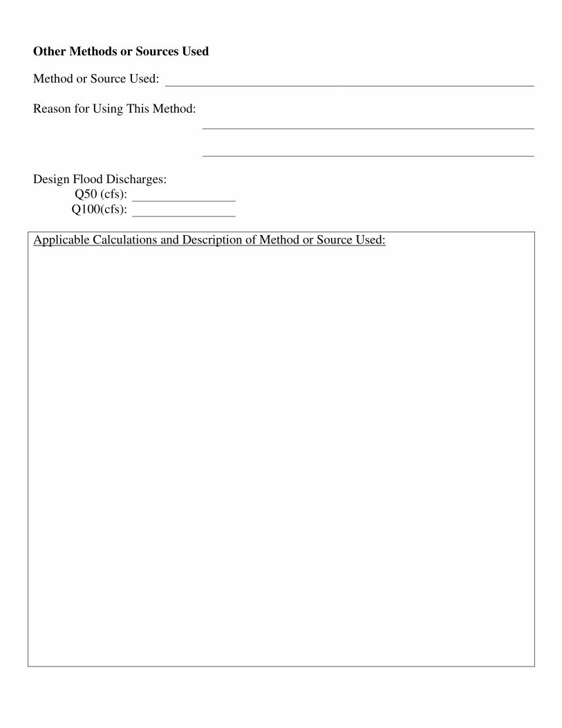
Other Methods or Sources Used
Method or Source Used:
Reason for Using This Method:
Design Flood Discharges:
Q50 (cfs):
Q100(cfs):
Applicable Calculations and Description of Method or Source Used:
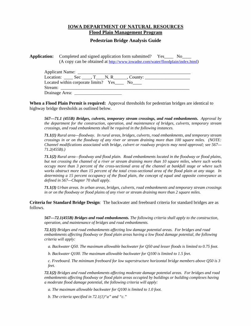
IOWA DEPARTMENT OF NATURAL RESOURCES Flood Plain Management Program
Pedestrian Bridge Analysis Guide Application: Completed and signed application form submitted? Yes____ No____ (A copy can be obtained at http://www.iowadnr.com/water/floodplain/index.html) Applicant Name: __________________________________________________ Location: ____ Sec ____, T____N, R______, County: ____________________ Located within corporate limits? Yes____ No____ Stream: _________________________________________________________ Drainage Area: _____________________ When a Flood Plain Permit is required: Approval thresholds for pedestrian bridges are identical to highway bridge thresholds as outlined below.
567—71.1 (455B) Bridges, culverts, temporary stream crossings, and road embankments. Approval by the department for the construction, operation, and maintenance of bridges, culverts, temporary stream crossings, and road embankments shall be required in the following instances.
71.1(1) Rural area—floodway. In rural areas, bridges, culverts, road embankments, and temporary stream crossings in or on the floodway of any river or stream draining more than 100 square miles. (NOTE: Channel modifications associated with bridge, culvert or roadway projects may need approval; see 567—71.2(455B).)
71.1(2) Rural area—floodway and flood plain. Road embankments located in the floodway or flood plains, but not crossing the channel of a river or stream draining more than 10 square miles, where such works occupy more than 3 percent of the cross-sectional area of the channel at bankfull stage or where such works obstruct more than 15 percent of the total cross-sectional area of the flood plain at any stage. In determining a 15 percent occupancy of the flood plain, the concept of equal and opposite conveyance as defined in 567—Chapter 70 shall apply.
71.1(3) Urban areas. In urban areas, bridges, culverts, road embankments and temporary stream crossings in or on the floodway or flood plains of any river or stream draining more than 2 square miles.
Criteria for Standard Bridge Design: The backwater and freeboard criteria for standard bridges are as follows.
567—72.1(455B) Bridges and road embankments. The following criteria shall apply to the construction, operation, and maintenance of bridges and road embankments.
72.1(1) Bridges and road embankments affecting low damage potential areas. For bridges and road embankments affecting floodway or flood plain areas having a low flood damage potential, the following criteria will apply:
a. Backwater Q50. The maximum allowable backwater for Q50 and lesser floods is limited to 0.75 foot.
b. Backwater Q100. The maximum allowable backwater for Q100 is limited to 1.5 feet.
c. Freeboard. The minimum freeboard for low superstructure horizontal bridge members above Q50 is 3 feet.
72.1(2) Bridges and road embankments affecting moderate damage potential areas. For bridges and road embankments affecting floodway or flood plain areas occupied by buildings or building complexes having a moderate flood damage potential, the following criteria will apply:
a. The maximum allowable backwater for Q100 is limited to 1.0 foot.
b. The criteria specified in 72.1(1)“a” and “c.”

Rev. 2/26/2007
72.1(3) Bridges and road embankments affecting high or maximum damage potential development. For bridges and road embankments affecting floodway or flood plain areas occupied by buildings or building complexes having a high or maximum flood damage potential, the following criteria will apply:
a. Backwater effects are to be minimized for all stages which affect maximum or high flood damage potential buildings or building complexes or for all stages which would tend to reduce the level of protection of certain flood control works, unless acceptable remedial measures are provided or such buildings are removed or the uses relating to human occupancy are prohibited.
b. In no case shall the criteria specified in 72.1(1)“a” and “c” and 72.1(2)“a” be exceeded.
72.1(4) Bridge and channel change. For bridges and culverts involving channel changes on the floodway of any stream draining at the location of the channel change between 10 and 100 square miles whereby either (i) more than a 500-foot length of the existing channel is being altered or (ii) the length of existing channel being altered is reduced by more than 25 percent, the maximum allowable backwater shall correspond to the limits permitted in 72.1(1), 72.1(2), 72.1(3) or 72.1(5) depending upon the associated damage potential.
Design Approaches: The design of a pedestrian bridge can be approached in 2 different ways:
Standard Bridge Design: One option is to approach the design as if it were a normal road bridge with elevated approach grades. The design would need to meet applicable department criteria with respect to backwater and freeboard as outlined in 567-72.3, Iowa Administrative Code (listed above). When using this standard bridge design option, the review procedure outlined in the DNR's Bridge Analysis Guide should be followed.
Alternate Design: An alternate design option which works well on small streams involves keeping the pedestrian trail and bridge approaches on-grade and spanning the stream channel from bank to bank. If designed with low profile girders and minimally obstructing railings, these bridges will generally create negligible obstruction to flood flows. Approach grades for these types of bridges must be minimized so as to result in little or no obstruction of overbank flow. Often times, hydraulic modeling of these bridges will not be required. However, on streams where FEMA has published a detailed Flood Insurance Study (FIS), it will be necessary to provide the hydraulic modeling needed to certify that the bridge will result in “no rise” in the 100-year flood profile.
These low bridges typically do not meet department freeboard criterion and therefore, will require a variance to that criterion. As part of the freeboard variance justification, it may be necessary to submit a certification that the bridge can withstand the buoyant and hydrodynamic forces associated with the 100-year flood. When opting for this alternate bridge design, it is recommended that a concept design be submitted to assure that this alternate design is applicable for the site. Design plans for this alternate design should include: a to-scale site plan showing the stream, trail, bridge and other pertinent physical features; a cross-section of the stream along the centerline of the bridge showing the abutments, girder profile and bridge railings; and a trail profile, including natural ground where it is located on the flood plain.

Iowa Department of Natural Resources
Checklist for Bridge Project Applications
FPMP:BC: Version 11/27/06
In order for this project to be reviewed in the shortest time possible, we ask that you make
certain that the following items are included with your bridge application
� Completed and Signed Application
� IDOT Form 1E (if applicable)
� 2-Sets of Design Plans (full size) Containing the Following:
� Survey Datum Reference
� North Arrow
� Site Map
� Pier Width
� Elevation of Low Chord
� Elevation of Low Point in Approach Grade
� Existing Bridge Data (if applicable)
� Hydrologic Calculations (50 yr. & 100 yr. floods)
� Hydraulic Calculations, Including the Following (where applicable):
� Plotted Valley Cross-Section (for Hydraulic Design Series 1 Review)
� Map Showing Location of All Valley Cross-Sections Used
� Summary of Hydraulic Calculations, Including Stream Slope, Velocity, Backwater
and Freeboard for 50 yr. and 100 yr. flows.
� Hard copy of all hydraulic models (for HECRAS, DOT Bridge Backwater, etc.)
� Disk with copy of all hydraulic models (for HECRAS, DOT Bridge Backwater, etc.)
� Variance Request Letter (if applicable)

1
Date: ___________
Completed By: __________________
Bridge Analysis Guide
1. Application: Completed and Signed Joint Application Form Submitted? Yes_____ No_____
Applicant Name: _________________________________
Location: _______ Sec _______, T_______N, R________ , County: ____________________
Stream(s): ________________________________________________________________
2. When Permit Required:
567—71.1 (455B) Bridges, culverts, temporary stream crossings, and road embankments. Approval by the department for the
construction, operation, and maintenance of bridges, culverts, temporary stream crossings, and road embankments shall be required in the
following instances.
71.1(1) Rural area—floodway. In rural areas, bridges, culverts, road embankments, and temporary stream crossings in or on the floodway
of any river or stream draining more than 100 square miles. (NOTE: Channel modifications associated with bridge, culvert or roadway
projects may need approval; see 567—71.2(455B).)
71.1(2) Rural area—floodway and flood plain. Road embankments located in the floodway or flood plains, but not crossing the channel of
a river or stream draining more than 10 square miles, where such works occupy more than 3 percent of the cross-sectional area of the
channel at bankfull stage or where such works obstruct more than 15 percent of the total cross-sectional area of the flood plain at any
stage. In determining a 15 percent occupancy of the flood plain, the concept of equal and opposite conveyance as defined in 567—Chapter
70 shall apply.
71.1(3) Urban areas. In urban areas, bridges, culverts, road embankments and temporary stream crossings in or on the floodway or flood
plains of any river or stream draining more than 2 square miles.
567—71.2 (455B) Channel changes. Approval by the department for the construction, operation, and maintenance of channel changes
shall be required in the following instances.
71.2(1) Rural areas. In rural areas:
b. Channel changes associated with road projects in or on the floodway of any stream draining more than 10 square miles at the
location of the channel change whereby either (i) more than a 500-foot length of the existing channel is being altered or (ii) the length of
existing channel being altered is reduced by more than 25 percent.
71.2(2) Urban areas. In urban areas channel changes on any river or stream draining more than 2 square miles at the location of the
channel change.
Located within a Corporate Limits? Yes ______ No ______
Drainage Area: ________________________ Approval Needed? Yes ______ No ______
Channel Change Involved? Yes ______ No ______
Channel Change >500 ft or reduces length by more than 25%? Yes ______ No ______

2
3. Engineering Plans: 2 Sets of Certified Plans Submitted? Yes ______ No ______
Location Map Included? Yes ______ No ______ (Quad Maps Available at http://ortho.gis.iastate.edu/)
Site Map Included? Yes ______ No ______
Survey Datum: ______________ (NGVD, other, explain)
Typical Stream Width: ______________ Typical Flood Plain Width: _____________
Channel Bottom Elevation: ___________ Average Flood Plain Elevation: __________
Record High Water Elevation: ______________ Date:______
Existing Bridge Length: _____________ Proposed Bridge Length: ______________
Bridge Skew (Degrees): Bridge to Stream: ______
Piers to Stream: ______
Abutments to Stream: ______
Low Steel (Chord) Elevation: At Right Abutment ___________
At Left Abutment ____________
At Mid Span __________
Abutment Berm Elevation: Left ___________ Right___________ Side Slopes: __________
Pier Width: __________ Pier Type (T-Pier, Pile Bent, other): ______________________________
Extent of Roadgrade Change (length, elevation, etc.): ______________________________________
_________________________________________________________________________________
Channel Excavation for Transition (expansion/contraction)? Yes ______ No ______
Explain: _________________________________________________________________
4. Hydraulics & Hydrology:
Does Community Have a Detailed Flood Insurance Study (FIS)? Yes _____ No _____ (If “Yes” continue
with Section 4.a. If “ No”, Skip to Section 4.b, for the situation where No Detailed FIS Exists for The Stream)
a. If “Yes”, Does Study Include Detailed Information (Floodway and 100 yr. Flood) Information For
this Stream? Yes _____ No _____ (If “No”, Skip to Section 4.b, for the situation where No Detailed FIS Exists
for The Stream).
Was Original Hydraulic Model Obtained From FEMA Library (703-236-7461)? Yes ___ No ___
If “No”, Explain: ________________________________________________________
If “No”, What is Source of Information? _____________________________________
______________________________________________________________________
3
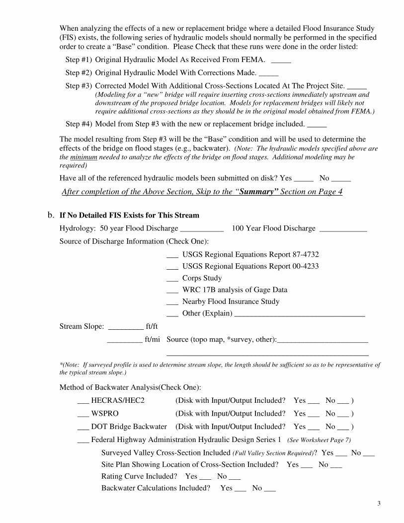
When analyzing the effects of a new or replacement bridge where a detailed Flood Insurance Study
(FIS) exists, the following series of hydraulic models should normally be performed in the specified
order to create a “Base” condition. Please Check that these runs were done in the order listed:
Step #1) Original Hydraulic Model As Received From FEMA. _____
Step #2) Original Hydraulic Model With Corrections Made. _____
Step #3) Corrected Model With Additional Cross-Sections Located At The Project Site. _____ (Modeling for a “new” bridge will require inserting cross-sections immediately upstream and
downstream of the proposed bridge location. Models for replacement bridges will likely not
require additional cross-sections as they should be in the original model obtained from FEMA.)
Step #4) Model from Step #3 with the new or replacement bridge included. _____
The model resulting from Step #3 will be the “Base” condition and will be used to determine the
effects of the bridge on flood stages (e.g., backwater). (Note: The hydraulic models specified above are
the minimum needed to analyze the effects of the bridge on flood stages. Additional modeling may be
required)
Have all of the referenced hydraulic models been submitted on disk? Yes _____ No _____
After completion of the Above Section, Skip to the “Summary” Section on Page 4
b. If No Detailed FIS Exists for This Stream
Hydrology: 50 year Flood Discharge ___________ 100 Year Flood Discharge ____________
Source of Discharge Information (Check One):
___ USGS Regional Equations Report 87-4732
___ USGS Regional Equations Report 00-4233
___ Corps Study
___ WRC 17B analysis of Gage Data
___ Nearby Flood Insurance Study
___ Other (Explain) _________________________________
Stream Slope: _________ ft/ft
_________ ft/mi Source (topo map, *survey, other):_______________________
___________________________________________________
*(Note: If surveyed profile is used to determine stream slope, the length should be sufficient so as to be representative of
the typical stream slope.)
Method of Backwater Analysis(Check One):
___ HECRAS/HEC2 (Disk with Input/Output Included? Yes ___ No ___ )
___ WSPRO (Disk with Input/Output Included? Yes ___ No ___ )
___ DOT Bridge Backwater (Disk with Input/Output Included? Yes ___ No ___ )
___ Federal Highway Administration Hydraulic Design Series 1 (See Worksheet Page 7)
Surveyed Valley Cross-Section Included (Full Valley Section Required)? Yes ___ No ___
Site Plan Showing Location of Cross-Section Included? Yes ___ No ___
Rating Curve Included? Yes ___ No ___
Backwater Calculations Included? Yes ___ No ___

4
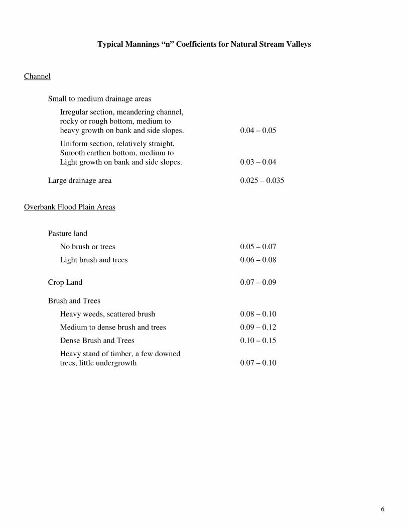
Mannings “n” Value Used:
Channel _______ Left Overbank ______ Right Overbank _____
(Typical “n” Values are listed on Page 6)
Photographs Included to Verify “n” Values? Yes ___ No ___
Upstream Damage Potential: ____________________________________
Field Verified? Yes ___ No ___
5. Summary:
50 yr. Flood 100 yr. Flood
Discharge (cfs) ______________ ______________
Water Surface Elev. ______________ ______________
Backwater ______________ ______________
*Velocity ______________ ______________
Freeboard ______________ ______________
Waterway Opening (sq. ft.) ______________ ______________
Road Grade Overflow (cfs) ______________ ______________
*Are Velocities Excessive? Yes ___ No ___. If “Yes”, What Stabilization Methods are Being
Used? ____________________________________________
6. Approval:
Approval Criteria:
567—72.1 (455B) Bridges and road embankments. The following criteria shall apply to the construction, operation, and
maintenance of bridges and road embankments.
72.1(1) Bridges and road embankments affecting low damage potential areas. For bridges and road embankments affecting floodway
or flood plain areas having a low flood damage potential, the following criteria will apply:
a. Backwater Q50. The maximum allowable backwater for Q50 and lesser floods is limited to 0.75 foot.
b. Backwater Q100. The maximum allowable backwater for Q100 is limited to 1.5 feet.
c. Freeboard. The minimum freeboard for low superstructure horizontal bridge members above Q50 is 3 feet.
Does Bridge Project Satisfy Criteria? Yes ___ No ___
Variance Requested? Yes ___ No ___
For (Check Appropriate Items): Freeboard ___ Backwater___

5
7. Variance: Criteria For Variance:
567— 72.31 (455B) Variance.
72.31(1) In general. Where evidence is presented that additional private or significant public damage will not result from flood plain
or floodway construction (other than channel changes) subject to regulation under 567—Chapters 70 to 72, the department may
permit variance to the criteria stated in Chapter 72.
Possible Justifications For Variance:
- Grade Constraints
- Easements Obtained for Areas Affected By Backwater
- Low Potential for Debris and Ice Accumulation
- Bridge Designed to Withstand Inundation
- Substantial Roadgrade Overflow
If variance is requested, explain justification for request: __________________________________
_________________________________________________________________________________________________
_________________________________________________________________________________________________
Note: A variance request should be made by letter and should include the above reference justification
and explanation.
8. Out of Order Processing Requested:
Criteria for Out of Order Processing:
567—70.5(2) (455B) Order of processing. In general, complete applications including sufficient plans and specifications shall be
reviewed in the order that complete information is received. However, when there are a large number of pending applications, which
preclude the department from promptly processing all applications, the department may expedite review of a particular application
out of order if the completed application and supporting documents were submitted at the earliest practicable time and any of the
following conditions exist:
a. Relatively little staff review time (generally less than four hours) is required and delay will cause the applicant hardship;
b. The applicant can demonstrate that a delay in the permit will result in a substantial cost increase of a large project;
c. Prompt review of the permit would result in earlier completion of a project that conveys a significant public benefit;
d. The need for a permit is the result of an unforeseen emergency or catastrophic event; or
e. A permit is needed to complete a project that will abate or prevent an imminent threat to the public health and welfare
Request Made for Out of Order Processing? Yes ___ No ___
If “Yes”, basis for request: _______________________________________________________
______________________________________________________________________________
6
Typical Mannings “n” Coefficients for Natural Stream Valleys
Channel
Small to medium drainage areas
Irregular section, meandering channel,
rocky or rough bottom, medium to
heavy growth on bank and side slopes. 0.04 – 0.05
Uniform section, relatively straight,
Smooth earthen bottom, medium to
Light growth on bank and side slopes. 0.03 – 0.04
Large drainage area 0.025 – 0.035
Overbank Flood Plain Areas
Pasture land
No brush or trees 0.05 – 0.07
Light brush and trees 0.06 – 0.08
Crop Land 0.07 – 0.09
Brush and Trees
Heavy weeds, scattered brush 0.08 – 0.10
Medium to dense brush and trees 0.09 – 0.12
Dense Brush and Trees 0.10 – 0.15
Heavy stand of timber, a few downed
trees, little undergrowth 0.07 – 0.10

7
Federal Highway Administration
Hydraulic Design Series No. 1
Bridge Backwater Analysis
Flood Frequency Data
50 yr. , ____________ cfs 100 yr. , ___________ cfs
Stage , ____________ ft. Stage , ____________ ft.
Velocity, __________ fps Velocity, __________ fps
Alpha (α1) , ________ Alpha(α1) , ________
Skew
Bridge (relative to stream) ______ degrees
Piers (relative to stream) ______ degrees
50 yr. Flood 100 yr. Flood
Bridge opening characteristics
(sq. ft.) An2 =
________________
________________
Skew Adjusted An2 = _____________ _____________
Roadgrade Overflow
(if applicable) cfs.
________________
________________ a) Q = CLH
3/2 =
C = 2.7 to 3.1
L = Length of weir
H = Head
= _____ _________ ____3/2
C ) ( L ) ( H )
= _____________
= _____ _________ ____3/2
C ) ( L ) ( H )
= _____________
B Width (ft.) (See Page 9 Attached)
B = Y
An2 , Y = depth
= = _________
= = __________
Flow Distribution
Qa = __________ __________
Qb = __________ __________
Qc = __________ __________
M = Total
b
Q
Q
= = _______
= = _______
Kb =
(Figure 6, HDS1, Page 10 Attached)
________________
________________
8
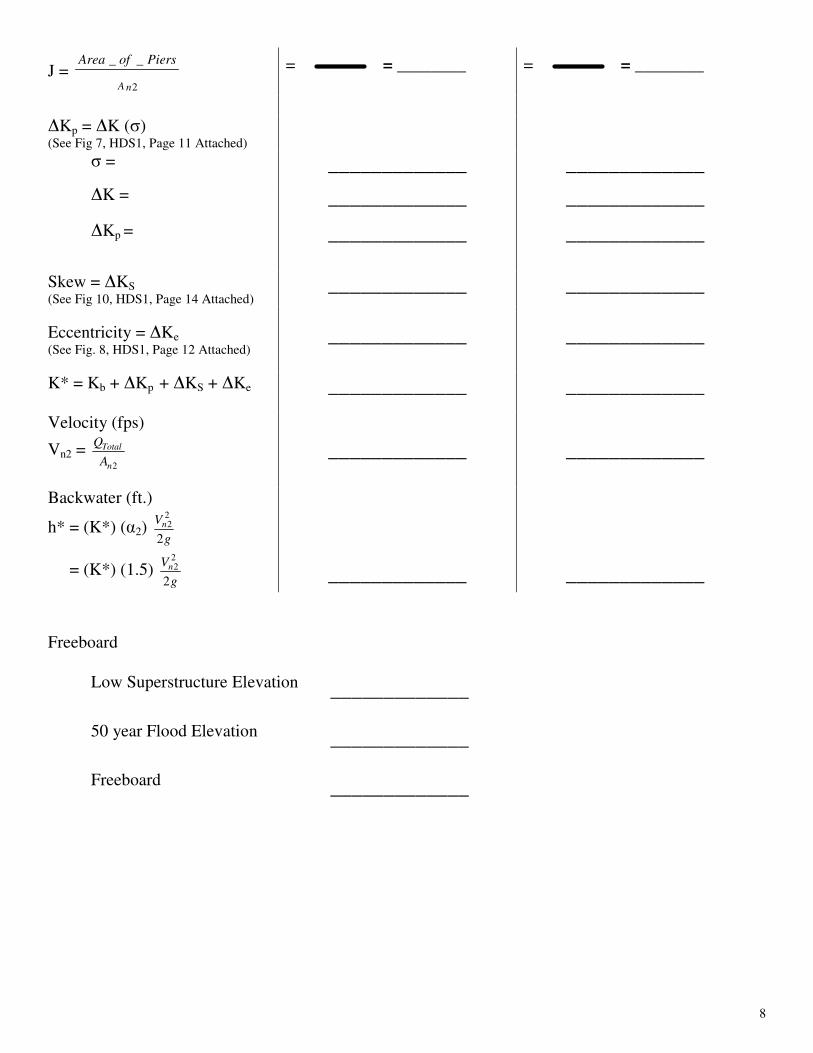
J = 2
__
nA
PiersofArea = = ________ = = ________
�Kp = �K (σ) (See Fig 7, HDS1, Page 11 Attached)
σ = _____________ _____________
�K = _____________ _____________
�Kp = _____________ _____________
Skew = �KS (See Fig 10, HDS1, Page 14 Attached)
_____________ _____________
Eccentricity = �Ke (See Fig. 8, HDS1, Page 12 Attached)
_____________ _____________
K* = Kb + �Kp + �KS + �Ke _____________ _____________
Velocity (fps)
Vn2 = 2n
Total
A
Q
_____________
_____________
Backwater (ft.)
h* = (K*) (α2) g
Vn
2
22
= (K*) (1.5) g
Vn
2
22
_____________
_____________
Freeboard
Low Superstructure Elevation
_____________
50 year Flood Elevation
_____________
Freeboard
_____________

9
The Following Figures Were Obtained From Federal Highway Administration
Hydraulic Design Series No. 1 (HDS 1)

10

11

12

13

14

15